integration of multilevel inverters with energy storage ... · pdf fileintegration of...
TRANSCRIPT

IJCSIET--International Journal of Computer Science information and Engg., Technologies ISSN 2277-4408 || 01062015-019
IJCSIET-ISSUE5-VOLUME2-SERIES2 Page 1
Integration of Multilevel inverters with energy storage systems for
hybrid vehicle applications
1Mr.Gattigunde Ramesh,2 Dr.J.NamrathaManohar 2Professor, EEE Department
1,2Lords Institute of Engineering and Technology, Hyderabad, India
Abstract
There are numbers of alternative energy resources
being studied for hybrid vehicles as preparation to
replace the exhausted supply of petroleum
worldwide. The use of fossil fuel in the vehicles is a
rising concern due to its harmful environmental
effects. Among other sources battery, fuel cell (FC),
super capacitors (SC) and photovoltaic cell i.e. solar
are studied for vehicle application. Combinations of
these sources of renewable energies can be applied
for hybrid electric vehicle (HEV) for next
generation of transportation. Various aspects and
techniques of HEV from energy management
system (EMS), power conditioning and propulsion
system are explored in this paper. Other related
fields of HEV such as DC machine and vehicle
system are also included. Various type models and
algorithms derived from simulation and experiment
are explained in details. The performances of the
various combination of HEV system are
summarized in the table along with relevant
references. This paper provides comprehensive
survey of hybrid electric vehicle on their source
combination, models, energy management system
(EMS) etc. developed by various researchers. From
the rigorous review, it is observed that the existing
technologies more or less can capable to perform
HEV well; however, the reliability and the
intelligent systems are still not up to the mark.
Accordingly, this review have been lighted many
factors, challenges and problems sustainable next
generation hybrid vehicle.
I. INTRODUCTION
AN energy storage system plays an important role in
electricvehicles (EV). Batteries, such as lead-acid or
lithiumbatteries, are the most popular units because
of their appropriateenergy density and cost. Since the
voltages of these kinds of batterycells are relatively
low, a large number of battery cells needto be
connected in series to meet the voltage requirement
of themotor drive [1], [2]. Because of the
manufacturing variab ility,cell arch itecture and
degradation with use, the characters such asvolume
and resistance will be different between these
cascadedbattery cells. In a trad itional method, all the
battery cells are directlyconnected in series and are
charged or discharged by thesame current, the
terminal voltage and state-of-charge (SOC)will be
different because of the electrochemical
characteristicdifferences between the battery cells.
The charge and
Discharges have to be stopped even though only one
of the cells reaches itscut-off voltage. Moreover,
when any cell is fatally damaged, thewhole battery
stack cannot be used anymore. So the battery cell
screening must be processed to reduce these
differences, andvoltage or SOC equalizat ion circuit is
often needed in practicalapplicat ions to protect the
battery cells from overcharging oroverdischarging
[3], [4].
Generally, there are two kinds of equalizat ion
circuits. Thefirst one consumes the redundant energy
on parallel resistanceto keep the terminal voltage of
all cells equal. For example,in charging course, if one
cell arrives at its cut-off voltage,the availab le energy
in other cells must be consumed in theirparallel-
connected resistances. So the energy utilizat ion ratio
isvery low. Another kind of equalizat ion circuit is
composed of agroup of inductances or transformers
and converters, which canrealize energy transfer
between battery cells. The energy in thecells with
higher terminal voltage or SOC can be transferred
toothers to realize the voltage and SOC equalization.
Since thevoltage balance is realized by energy
exchange between cells,
the energy utilizat ion ratio is improved. The
disadvantage is thata lot of inductances or isolated
multiwinding transformers arerequired in these
topologies, and the control of the convertersis also
complex [5]–[13]. Some studies have been
implementedto simplify the circuit and improve the
balance speed by multistageequalization [9]–[13].
Some zero voltage and zero currentswitching
techniques are also used to reduce the loss of
theequalization circuit [13].
Multilevel converters are widely used inmedium or
high voltagemotor drives [14]–[19]. If their fly ing

IJCSIET--International Journal of Computer Science information and Engg., Technologies ISSN 2277-4408 || 01062015-019
IJCSIET-ISSUE5-VOLUME2-SERIES2 Page 2
capacitors or isolateddc sources are replaced by the
battery cells, the battery cellscan be cascaded in
series combining with the converters insteadof
connection in series directly. In [20]–[24], the
cascaded Hbridgeconverters are used for the voltage
balance of the batterycells. Each H-bridge cell is used
to control one battery cell; thenthe voltage balance
can be realized by the separate control ofcharging
and discharging. The output voltage of the
converteris multilevel which is suitable for the motor
drives. When usedfor power grid, the filter
inductance can be greatly reduced. Thecascaded
topology has better fault-tolerant ability by its
modulardesign, and has no limitation on the number
of cascaded cells,so it is very suitable to produce a
higher voltage output usingthese low-voltage battery
cells, especially for the application inpower grid.
Similar to the voltage balance method in
traditionalmultilevel converters, especially to the
STATCOM using flyingcapacitors, the voltage
balance control of the battery cells can
Fig.1.Traditional power storage system with voltage
equalization circuit andinverter.
also be realized by the adjustment of the modulation
ratio ofeach H-bridge [25]. Compared to the
traditional voltage balancecircuit, the multilevel
converters are very suitable for thebalance of battery
cells. Besides the cascaded H-bridge circuit,some
other hybrid cascaded topologies are proposed in
[18], [19]which use fewer devices to realize the same
output. Because ofthe power density limitation of
batteries, some ultra-capacitorsare used to improve
the power density. Some converters must beused for
the battery and ultra-capacitor combination [26],
[27].Multilevel converters with battery cells are also
very convenientfor the combination of battery and
ultra-capacitors.
A hybrid cascaded multilevel converter is proposed
in thispaper which can realize the terminal voltage or
SOC balancebetween the battery cells. The converter
can also realize thecharge and discharge control of
the battery cells. A desired acvoltage can be output at
the H-bridge sides to drive the electricmotor, or to
connect to the power grid. So additional
batterychargers or motor drive inverters are not
necessary any moreunder this situation. The ac output
of the converter is multilevelvoltage, while the
number of voltage levels is proportional to thenumber
of cascaded battery cells. So in the applications of
EVor power grid with a larger number of battery
cells, the output acvoltage is approximately ideal sine
waves. The harmonics anddv/dt can be greatly
reduced than the traditional two-level converters.The
proposed converter with modular design can
realizethe fault redundancy and high reliab ility easily.
Simulation andexperimental results are proposed to
verify the performance ofthe proposed hybrid
cascaded mult ilevel converter in this paper.
II. TOPOLOGY OF THE HYBRID
CASCADEDMULTILEVEL
CONVERTER
One of the popular voltage balance circuits by energy
transferis shown in Fig. 1 [5], [28]. There is a half-
bridge arm andan inductance between every two
nearby battery cells. So thenumber of switching
devices in the balance circuit is 2∗n–2 andthe number
of inductance is n–1 where n is the number of
thebattery cells. In this circuit, an additional inverter
is needed forthe motor drive and a charger is usually
needed for the batteryrecharge [29]. In fact, if the
output of the inverter is connected
Fig.2.Hybrid cascaded mult ilevel converter.

IJCSIET--International Journal of Computer Science information and Engg., Technologies ISSN 2277-4408 || 01062015-019
IJCSIET-ISSUE5-VOLUME2-SERIES2 Page 3
With the three-phase ac source by some filter
inductances, thebattery recharge can also be realized
by an additional controlblock which is similar with
the PWM rectifier. The recharg ingcurrent and voltage
can be adjusted by the closed-loop voltageor power
control of the rectifier.
The hybrid-cascaded mult ilevel converter proposed
in thispaper is shown in Fig. 2, which includes two
parts, the cascadedhalf-bridges with battery cells
shown on the left and the Hbridgeinverters shown on
the right. The output of the cascadedhalf-bridges is
the dc bus which is also connected to the dcinput of
the H-bridge. Each half-bridge can make the
batterycell to be involved into the voltage producing
or to be bypassed.Therefore, by control of the
cascaded half-bridges, the numberof battery cells
connected in the circuit will be changed, thatleads to
a variable voltage to be produced at the dc bus.
TheH-bridge is just used to alternate the direction of
the dc voltageto produce ac waveforms. Hence, the
switching frequency ofdevices in the H-bridge equals
to the base frequency of thedesired ac voltage.
There are two kinds of power electronics devices in
the proposed circuit. One is the low voltage devices
used in the cascaded half-bridges which work in
higher switching frequency to reduce harmonics,
such as MOSFETs with low on-resistance. The other
is the higher voltage devices used in the H-bridges
which worked just in base frequency. So the high
voltage large capacity devices such as GTO or IGCT
can be used in the H-bridges.
The three-phase converter topology is shown in Fig.
3. If thenumber of battery cells in each phase is n,
then the devicesused in one phase cascaded half-
bridges is 2∗n. Compared tothe traditional
equalization circuit shown in Fig. 1, the numberof
devices is not increased significantly but the
inductancesare eliminated to enhanced the system
power density and EMIissues.
Since all the half-bridges can be controlled
individually, astaircase shape half-sinusoidal-wave
voltage can be producedon the dc bus and then a
multilevel ac voltage can be formed atthe output side
of the H-bridge, the number of ac voltage levelsis
2∗n–1 where n is the number of cascaded half-
bridges in each
Fig.3. Three-phase hybrid cascaded multilevel
converter.
Fig.4.Output voltage and current of the battery cell.
Phase. On the other hand, the more of the cascaded
cells, themore voltage levels at the output side, and
the output voltage iscloser to the ideal sinusoidal. The
dv/dt and the harmonics arevery little . So it is a
suitable topology for the energy storagesystem in
electric vehicles and power grid.
III. CONTROL METHOD OF THE
CONVERTER
For the cascade half-bridge converter, define the
switchingstate as follows:
The modulation rat io mx of each half bridge is
defined as theaverage value of the switching state in a
PWM period. In therelative half-bridge converter
shown in Fig. 4, when Sx = 1, thebattery is connected
in the circuit and is discharged or chargedwhich is

IJCSIET--International Journal of Computer Science information and Engg., Technologies ISSN 2277-4408 || 01062015-019
IJCSIET-ISSUE5-VOLUME2-SERIES2 Page 4
determined by the direction of the external
current.When Sx = 0, the battery cell is bypassed
from the circuit, thebattery is neither discharged nor
charged. When 0 < mx < 1,the half-bridge works in a
switching state. The instantaneousdischarging power
from this cell is.
P = Sx·ux· i. (1)
Here ux is the battery cell voltage and i is the
charging currenton the dc bus.
In the proposed converter, the H-bridge is just used to
alternatethe direction of the dc bus voltage, so the
reference voltage ofthe dc bus is the absolute value of
the ac reference voltage, justlike a half-sinusoidal-
wave at a steady state. It means that notall the battery
cells are needed to supply the load at the same
time. As the output current is the same for all cells
connectedin the circuit, the charged or discharged
energy of each cell isdetermined by the period of this
cell connected into the circuit,which can be used for
the voltage or energy equalization. Thecell with
higher voltage or SOC can be discharged more or
tobe charged less in using, then the energy utilizat ion
ratio canbe improved while the overcharge and
overdischarged can beavoided.
For the cascaded multilevel converters, generally
there aretwo kinds modulation method: phase-shift
PWM and carriercascadedPWM. As the terminal
voltage or SOC balance controlmust be realized by
the PWM, so the carrier-cascaded PWM issuitable as
the modulation ratio difference between differentcells
can be used for the balance control [30]– [32].
In the carrier-cascaded PWM, only one half-bridge
converterin each phase is allowed to work in
switching state, the otherskeep their state
unchangeable with Sx= 1 or Sx= 0, so theswitching
loss can be reduced. When the converter is used
tofeed a load, or supply power to the power grid, the
batterywith higher terminal voltage or SOC is
preferentially used toform the dc bus voltage with
Sx= 1. The battery with lowerterminal voltage or
SOC will be controlled in switch state with0 < mx <1
or be bypassed with Sx= 0.
The control of the converter and voltage equalizat ion
canbe realized by a modified carrier-cascaded PWM
method asshown in Fig. 5. The position of the battery
cells in the carrierwave is determined by their
terminal voltages. In the dischargingprocess, the
battery cells with higher voltage are placed at
thebottom layer of the carrier wave while the cells
with lowervoltage at the top layer. Then, the cells at
the top layer will beused less and less energy is
consumed from these cells.
In the proposed PWM method, the carrier arranged
by terminalvoltage can realize the terminal voltage
balance, while thecarrier arranged by SOC can realize
the SOC balance. Since theSOC is difficu lt to be
estimated in the batteries in practice, theterminal
voltage balance is usually used. Normally, the cut-off
voltage during charge and discharge will not change
in spite ofthe variation of manufacturing variability,
cell architecture, anddegradation with use. So the
overcharge and overdischarge canalso be eliminated
even the terminal voltages are used insteadof the
SOC for the carrier-wave arrangement.
To reduce the dv/dtand EMI, only one half-bridge is
allowedto change its switching state at the same time
for the continuousreference voltage. Therefore, the
carrier wave is only rearrangedwhen the modulation
wave is zero and the rearranged carrieronly becomes
effective when the carrier wave is zero. So thecarrier
wave is only rearranged at most twice during one
referenceac voltage cycle as shown in Fig. 6. The
battery’s terminalvoltage and SOC change very
slowly during the normal use, sothe carrier wave
updated by base frequency is enough for thevoltage
and SOC balance.
If the number of the cascaded cells is large enough,
all thehalf-bridges can just work in switch-on or
switch-off state toform the staircase shape voltage.
So the switching frequencyof all the half-bridges can
only be base frequency as shownin Fig. 6, where the
output ac voltage is still very approach tothe ideal
sinusoidal wave which is similar with the
multilevelconverter in [32].
Fig.5. Carrier wave during discharging.

IJCSIET--International Journal of Computer Science information and Engg., Technologies ISSN 2277-4408 || 01062015-019
IJCSIET-ISSUE5-VOLUME2-SERIES2 Page 5
Fig.6.Base frequency modulation.
When one cell is damaged, the half-bridge can be
bypassed,and there is no influence on the other cells.
The output voltage ofthe phase with bypassed cell
will be reduced. For symmetry, thethree-phase
reference voltage must be reduced to fit the
outputvoltage ability. To improve the output voltage,
the neutral shiftthree-phase PWM can be adopted.
The bypass method and theneutral shift PWM is very
similar with the method explainedin [20], [21].
IV. LOSS ANALYSIS AND
COMPARISON
Compared to the traditional circuit in Fig. 1, the
circuit topologyand voltage balance process is quite
different. In the traditionalcircuit in Fig. 1, the three-
phase two-level inverter is usedfor the discharging
control and the energy transfer circuit is usedfor the
voltage balance. In the proposed hybrid-cascaded
circuit,the cascaded half-bridges are used for voltage
balance controland also the discharging control
associated with the H-bridgeconverters. The
switching loss and the conduction losses in thesetwo
circuits are quite different. To do a clear comparison,
theswitching and conduction loss is analyzed in this
section.
In the hybrid-cascaded converter, the energy loss is
composedof several parts
JLoss = Js B + JsH+Jc B + JcH . (2)
Here, Js_ B and Js _H are the switching losses of the
cascadedhalf-bridges and the H-bridge converters,
while Jc_ H and Jc_ Bare the conduction losses.
Fig.7. DC bus voltage output by the cascaded half-
bridgesFFT Analysis of Existing system..
In the traditional circuit as shown in Fig. 1, the
energy loss iscomposed by
JLoss = Js I+Js T + Jc I + Jc T (3)
Where Js_ I and Js_ T are the switching losses of the
three-phaseinverter and the energy transfer circuit for
voltage balance.Jc_ Iand Jc_ T are the conduction
losses. In the traditional circuit, theenergy transfer
circuit onlyworks when there is some imbalanceand
only the parts between the unbalance cells need to
work.So the switching and conduction losses will be
very small if thebattery cells are symmetrical.
First, the switching loss is analyzed and compared
under therequirement of same switching times in the
output ac voltage.That means the equivalent
switching frequency of the cascadedhalf-bridges in
hybrid-cascaded converter is the same as
thetraditional inverter. The switching loss is
determined by thevoltage and current stress on the
semiconductor devices, andalso the switching time
(4)
In the proposed hybrid-cascaded converter, the H-
bridge converteris only used to alternate the direction
of the output voltageto produce the desired ac voltage
as shown in Fig. 7, the devicesin the H-bridge

IJCSIET--International Journal of Computer Science information and Engg., Technologies ISSN 2277-4408 || 01062015-019
IJCSIET-ISSUE5-VOLUME2-SERIES2 Page 6
converter always switch when the dc bus voltageis
zero. So the switching loss of the H-bridge is almost
zero
(5)
The equivalent switching frequency of the half-
bridges is thesame as the traditional converter, but
only one half-bridge isactive at the any instantaneous
in each phase. The voltage stepof each half-bridge is
only the battery cell voltage which is muchlower than
the whole dc bus voltage in Fig. 1. So in a single
Switching course, the switching loss is only
approximate 1/n ofthe one in traditional converter if
the same device is adopted inboth converters.
Furthermore, if the lower conduction voltagedrop and
faster turn-off device such as MOSFET is used in
theproposed converter, the switching loss of the half-
bridge will bemuch s maller
Js B < Js I /n. (6)
In the traditional circuit, the voltage balance circuit
will stillcause some switching loss determined by the
voltage imbalance.So in the proposed new topology,
the switching loss is muchsmaller compared to the
traditional two-level inverter
TABLE I
COMPARISON OF THE SWITCHING AND
CONDUCTION LOSS OF THE PROPOSED
CIRCUIT AND THE TRADITIONAL ONE.
The conduction loss is determined by the on-
resistance of theswitching devices and the current
value. Whatever the switchingstate, one switch
device in each half-bridge and two devices inH-
bridge are connected in the circuit of each phase, so
theconduction loss power can be calculated by
Pc B = I2Rc B · n (7)
Pc H = I2Rc H · 2. (8)
Here, I is the rms value of the output current, Rc_ B
is theon-resistance of the MOSFET in the half-
bridge, Rc_ H is thedevice on-resistance used in the
H-bridge, and n is the numberof the cascaded cells.
In the traditional three-phase inverter, only one
device is connectedin the circuit of each phase, the
conduction loss powerin each phase is just
Pc I = I2Rc I (9)
whereRc I is the on-resistance of the devices used in
the inverter.Normally, the same semiconductor
devices can be usedin the H-bridges and the
traditional three-phase inverters, sothe on-resistance
of the inverters is almost the same as the Hbridges.
The on-loss of the H-bridges cannot be reduced,
while theon-loss on cascaded half-bridges can be
reduced furthermoreby reducing the number o f the
cascaded cells. In practical applications,the battery
module of 12 and 24 V can be used for thecascaded
cells instead of the basic battery cell with only 2–3 V.
Also the semiconductor devices with low on-
resistance are usedin the half-bridges.
From the above analysis, the switching loss of the
proposedconverter is much less than the traditional
converter, althoughthe on-loss is larger than the
traditional converter. The comparedresults are shown
in Table I.
V. CHARGING METHOD
In the system using the proposed circuit in this paper,
a dcvoltage source is needed for the battery charging.
The chargingcurrent and voltage can be controlled by
the proposed converteritself according to the
necessity of the battery cells.. A circu it breaker is
used to switch the
Fig.8. Carrier waves during charging.

IJCSIET--International Journal of Computer Science information and Engg., Technologies ISSN 2277-4408 || 01062015-019
IJCSIET-ISSUE5-VOLUME2-SERIES2 Page 7
Fig.9.Charging circuit of battery with dc source.
Fig.10. Charging circuit of battery with ac source.
dc bus from the H-bridge to the dc voltage source.
Furthermore,a filter inductor is connected in series
with the dc source torealize the current control. The
dc voltage can also be realizedby the H-bridge and a
capacitor. The H-bridgeworked as a rectifier by the
diodes and a steady dc voltage isproduced with the
help of the capacitors.
In the charging course of the battery, the charging
currentshould be controlled. The current state
equation is as follows:
(10)
Here, udc is the dc bus voltage output by the
cascaded halfbridges,ucharge is the voltage of the dc
source, and Rf , Lfare the resistance and inductance
of the inductive filter betweenthe cascaded half-
bridges and the dc source. By this chargingmethod,
the voltage of the dc source must be smaller than
thepossible maximum value of the dc bus
ucharge ≤ udc ≤ n · u0 . (11)
Fig.10. Current control scheme for the battery
charging.
Fig.11.Output waveform for pulse generation circuit
Here, n is the number of the cascade half-bridges in
each phaseand u0 is the discharging cut-off voltage
of the battery cell.
During the charging cycle, the voltages of the battery
cells andthe dc voltage source might be variable, so
the switching states ofthe cascaded half-bridges will
be switched to make the chargingcurrent constant.
The charging current control scheme is shownin Fig.
10. A PI regulator is used to make the current
constantby changing the output dc voltages of the
cascaded cells. Thevoltage of the dc source is used as
a feed-forward compensationat the output of the PI
controller. In practical applications, thevalue of the
dc source’s voltage is almost constant, so the
feedforwardcompensation can also be removed and
the variation ofthe dc source voltage can be
compensated by the feedback ofthe PI controller.
In charging state, the arrangement of the carrier
waves willbe opposite with discharge state. The
battery cell with lowervoltage will be placed in the

IJCSIET--International Journal of Computer Science information and Engg., Technologies ISSN 2277-4408 || 01062015-019
IJCSIET-ISSUE5-VOLUME2-SERIES2 Page 8
bottom then these cells will absorbmore energy from
the dc source. The cells with higher voltageswill be
arranged at the top levels to make these cells
absorbless energy. By the similar analysis as the
discharging state, thepositions of the carrier waves in
charge state are shown in Fig. 8.During the
regeneration mode of the motor drive, for
example,when the EV is braking, the battery cells are
also charged, sothe modulation will also be changed
to the charging mode asshown in Fig. 11.
The energy charged into the battery cell is the same
as (1)
(12)
whereSxis the switching state of the bridge arms and i
is thecharging current controlled by the scheme
shown in Fig. 9.
When the reference dc bus voltage is variable, such
as thehalf-sinusoidal-wave, all the battery cells will
be charged intermittently. Thatis similar to the fast-
charge method of the battery to improve the charging
speed [33]. So the charging current in the
proposedconverter can be larger than the ordinary
charging method. Whenthe battery stack is charged
by a steady dc source, the referencedc bus voltage is
nearly constant. To realize the fast-charge ofthe
battery cell, the carrier-wave must be forced to
exchange theposition which is not arranged by the
SOC or terminal voltagesany more. Then, the
switching state of the half-bridges will bechanged to
produce intermittently charging current.
VI. EXPERIMENTAL RESULTS
To verify the performance of the proposed topology
andthe control method, a three-phase four-cell
cascaded circuit iserected at lab. The platform is
shown in Fig. 13. The lead-acidbattery modules of 5
Ah and 12 V are used. The battery modulesare
monitored by the LEM Sentinel which can
measurethe voltage, temperature, and resistance of
the battery modules.Themeasured information is
transferred to theDSP controller byRS-232
communicat ion. The voltages and currents are
measuredand recorded by YOKOGAWA Scope order
DL750. Since theSOC of the battery cells are d ifficult
to be estimated, the terminalvoltages are used for the
PWM carrier-wave arrangement;
Fig.12. Triphase output voltage of mult ilevel.
Then the terminal vo ltage balance is realized instead
of the SOCbalance which can still verify the effects
of the converter.
The cascaded half-bridges are designed with
MOSFETIPP045N10N3 (Infineon) whose on-
resistance is only 4.2 mΩand the rated current is 100
A. Even if the discharge or chargecurrent is 50 A, the
conduction loss on the MOSFET of eachhalf-bridge
is only
P = I2R = 10.5W.
Then, the efficiency drop caused by the conduction
loss of theMOSFET in the whole phase is
So the conduction loss added by the equalizat ion
circuit is verysmall compared to the output power of
the whole converter.Another device of MOSFET
IPB22N03S4L-15 (Infineon) of30 V, 22 A, and 14.6
mΩ will be used in our platform. The efficiencydrop
caused by the conduction loss Δη = 1.38% whenthe
output current is 11 A.
The three-phase output voltage is shown in Fig. 12.
Thereare nine levels at each phase. So it approaches
more to theideal sinusoidal wave than the traditional
two-level inverters. Ina steady state, the FFT analysis
result of the output ac phasevoltage is shown in Fig.
14. It shows that the harmonics is littlecompared to
the base-frequency component.
An induction motor (IM) was driven with the
variablevoltage–variable-frequency (VVVF) control
method. The parametersof the motor are shown in
Table II.

IJCSIET--International Journal of Computer Science information and Engg., Technologies ISSN 2277-4408 || 01062015-019
IJCSIET-ISSUE5-VOLUME2-SERIES2 Page 9
The dc bus voltage, ac output voltage, output current,
anddc bus current are shown in and 14, which
indicate thewhole process from start-up to the stable
state of the relative IM As the lagbetween the voltage
and current phase, when the phase voltagechange
direction, the H-bridge will change its switching
statetoo. But the phase ac current will change its
direction after a
Fig.13. FFT analysis of the output ac voltage.
TABLE II
PARAMETERS OF THE INDUCTION MOTOR
.period of time, so the direction of the dc bus current
is reversedwhen the directions of phase voltage and
current are different.The reversed dc bus current also
reflects the reactive power ofthe load. As the
induction motor is of nearly no load, the phasecurrent
is nearly π/2 lag with the phase voltage and the
averagedc current is almost zero in steady state. But
in starting course,
Fig.14 .Output voltage and current
Fig.15. DC bus current with some loads.
the average dc bus voltage is positive which stands
for the active power flow from the battery to the
electric motor
When there is some load on the motor, the dc bus
current is shown in Fig. 15. The reversed current is
greatly reduced which means the average power is
flowed from the converter to the motor.
When the charging method introduced in above
section is usedwith a steady dc source, the cascaded
half-bridges are connectedwith the dc source first,
then a charging current reference isgiven, the output
dc bus voltage and the dc current of the wholecourse
are recorded as a single figure by the
YOKOGAWAScopeCorder.
IJCSIET--International Journal of Computer Science information and Engg., Technologies ISSN 2277-4408 || 01062015-019
IJCSIET-ISSUE5-VOLUME2-SERIES2 Page 10
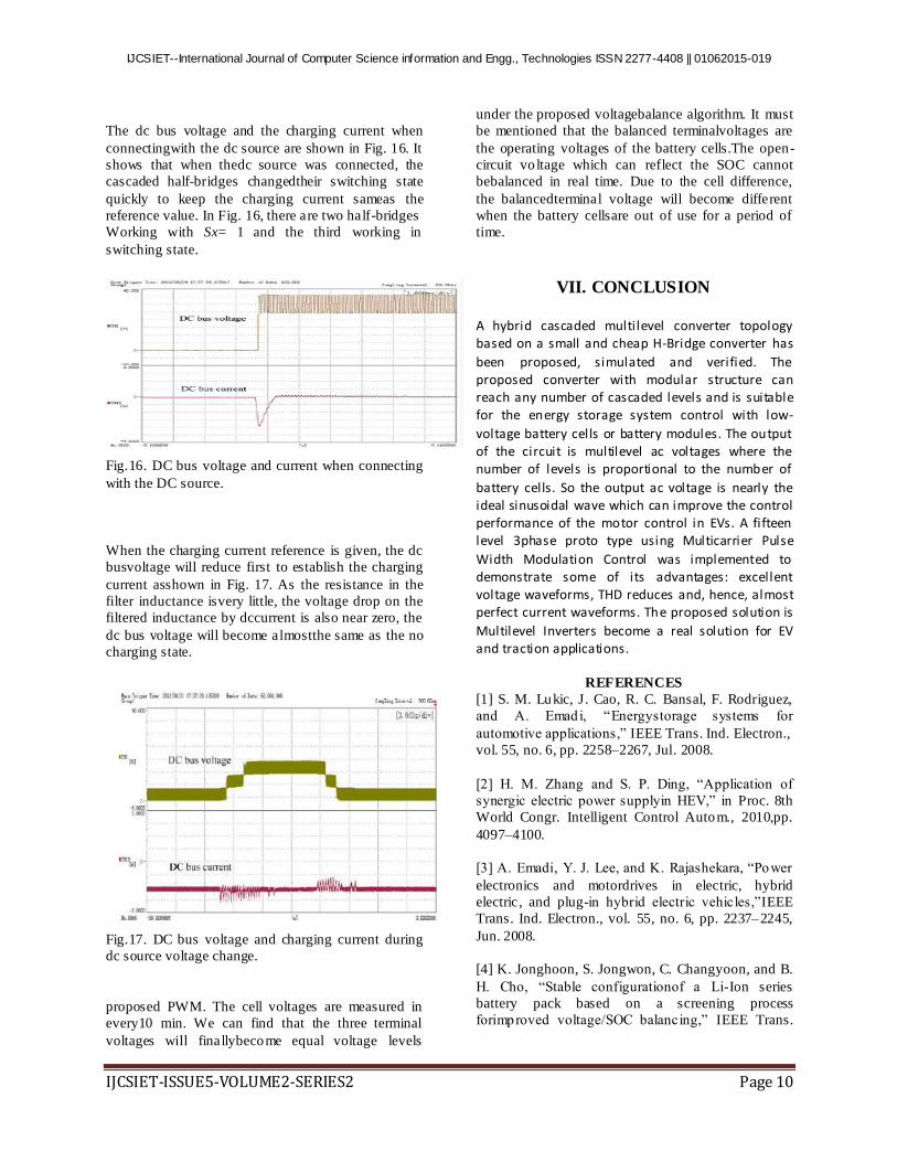
The dc bus voltage and the charging current when
connectingwith the dc source are shown in Fig. 16. It
shows that when thedc source was connected, the
cascaded half-bridges changedtheir switching state
quickly to keep the charging current sameas the
reference value. In Fig. 16, there are two half-bridges
Working with Sx= 1 and the third working in
switching state.
Fig.16. DC bus voltage and current when connecting
with the DC source.
When the charging current reference is given, the dc
busvoltage will reduce first to establish the charging
current asshown in Fig. 17. As the resistance in the
filter inductance isvery little, the voltage drop on the
filtered inductance by dccurrent is also near zero, the
dc bus voltage will become almostthe same as the no
charging state.
Fig.17. DC bus voltage and charging current during
dc source voltage change.
proposed PWM. The cell voltages are measured in
every10 min. We can find that the three terminal
voltages will finallybecome equal voltage levels
under the proposed voltagebalance algorithm. It must
be mentioned that the balanced terminalvoltages are
the operating voltages of the battery cells.The open-
circuit vo ltage which can reflect the SOC cannot
bebalanced in real time. Due to the cell difference,
the balancedterminal voltage will become different
when the battery cellsare out of use for a period of
time.
VII. CONCLUSION
A hybrid cascaded multilevel converter topology based on a small and cheap H-Bridge converter has
been proposed, simulated and verified. The proposed converter with modular structure can reach any number of cascaded levels and is suitable for the energy storage system control with low-
voltage battery cells or battery modules. The output of the circuit is multilevel ac voltages where the number of levels is proportional to the number of
battery cells. So the output ac voltage is nearly the ideal sinusoidal wave which can improve the control performance of the motor control in EVs. A fifteen level 3phase proto type using Multicarrier Pulse
Width Modulation Control was implemented to demonstrate some of its advantages: excellent voltage waveforms, THD reduces and, hence, almost perfect current waveforms. The proposed solution is
Multilevel Inverters become a real solution for EV and traction applications.
REFERENCES
[1] S. M. Lukic, J. Cao, R. C. Bansal, F. Rodriguez,
and A. Emadi, “Energystorage systems for
automotive applications,” IEEE Trans. Ind. Electron.,
vol. 55, no. 6, pp. 2258–2267, Jul. 2008.
[2] H. M. Zhang and S. P. Ding, “Application of
synergic electric power supplyin HEV,” in Proc. 8th
World Congr. Intelligent Control Autom., 2010,pp.
4097–4100.
[3] A. Emadi, Y. J. Lee, and K. Rajashekara, “Power
electronics and motordrives in electric, hybrid
electric, and plug-in hybrid electric vehicles,”IEEE
Trans. Ind. Electron., vol. 55, no. 6, pp. 2237–2245,
Jun. 2008.
[4] K. Jonghoon, S. Jongwon, C. Changyoon, and B.
H. Cho, “Stable configurationof a Li-Ion series
battery pack based on a screening process
forimproved voltage/SOC balancing,” IEEE Trans.

IJCSIET--International Journal of Computer Science information and Engg., Technologies ISSN 2277-4408 || 01062015-019
IJCSIET-ISSUE5-VOLUME2-SERIES2 Page 11
Power Electron., vol. 27,no. 1, pp. 411–424, Jan.
2012.
[5] L. Yuang-Shung, T. Cheng-En, K. Yi-Pin, and C.
Ming-Wang, “Chargeequalization using quasi-
resonant converters in battery string for
medicalpower operated vehicle application,” in Proc.
Int. Power Electron. Conf.,2010, pp. 2722–2728.
[6] Y. C. Hsieh, C. S. Moo, and W. Y. Ou-Yang, “A
bi-directional chargeequalization circu it for series -
connected batteries,” in Proc. IEEE PowerElectron.
Drives Syst., 2005, pp. 1578–1583.
[7] S.Yarlagadda, T. T.Hartley, and I.Husain,
“Abatterymanagement systemusing an active charge
equalization technique based on a DC/DC converter
topology,” in Proc. Energy Convers. Congr.Expo.,
2011, pp. 1188–1195.
[8] K. Chol-Ho, K. Young-Do, and M. Gun-Woo,
“Individual cell voltageequalizer using selective two
current paths for series connected Li-ionbattery
strings,” in Proc. Energy Convers. Congr.Expo.,
2009, pp. 1812–1817.
[9] H. Shen, W. Zhu, and W. Chen, “Charge
equalization using multiplewinding magnetic model
for lithium-ion battery string,” in Proc. Asia-Pacific
Power Energy Eng. Conf., 2010, pp. 1–4.
[10] P. Sang-Hyun, P. Ki-Bum, K. Hyoung-Suk, M.
Gun-Woo, and Y. Myung-Joong, “Single-magnetic
cell-to-cell charge equalization converter withreduced
number of transformer windings,” IEEE Trans.
Power Electron.,vol. 27, no. 6, pp. 2900–2911, Jun.
2012.
[11] K. Chol-Ho, K. Moon-Young, P. Hong-Sun, and
M. Gun-Woo, “A modularizedtwo -stage charge
equalizer with cell selection switches for
seriesconnectedlithium-ion battery string in an
HEV,” IEEE Trans. PowerElectron., vol. 27, no. 8,
pp. 3764–3774, Aug. 2012.
[12] K. Chol-Ho, K. Moon-Young, and M. Gun-
Woo, “A modularized chargeequalizer using a
batterymonitoring IC for series-connected Li-Ion
batterystrings in electric vehicles,” IEEE Trans.
Power Electron., vol. 28, no. 8,pp. 3779–3787, Aug.
2013.
[13] Y. Ye, K. W. E. Cheng, and Y. P. B. Yeung,
“Zero-current switchingswitched-capacitor zero-
voltage-gap automatic equalization system for series
battery string,” IEEE Trans. Power Electron., vol. 27,
no. 7, pp. 3234–3242, Ju l. 2012.
[14] L. M. Tolbert, Z. P. Fang, and T. G. Habetler,
“Multilevel converters forlarge electric drives,” IEEE
Trans. Ind. Appl., vol. 35, no. 1, pp. 36–44,Jan. 1999.
[15] J. Rodriguez, S. Bernet, B. Wu, J. O. Pontt, and
S. Kouro, “MultilevelVoltage-source-converter
topologies for industrial medium-voltagedrives,”
IEEE Trans. Ind. Electron., vol. 54, no. 6, pp. 2930–
2945, Dec.2007.
[16] Z. Du, B. Ozpineci, L. M. Tolbert, and J. N.
Chiasson, “Inductor less DCACcascaded H-bridge
multilevel boost inverter for electric/hybrid
electricvehicle applications,” in Proc. IEEE Ind.
Appl. Conf., 2007, pp. 603–608.
[17] F. Khoucha, S. M. Lagoun, K. Marouani, A.
Kheloui, andM. E. H. Benbouzid, “Hybrid cascaded
H-bridge mult ilevel-inverterinduction-motor-drive
direct torque control for automotive
applications,”IEEE Trans. Ind. Electron., vol. 57, no.
9, pp. 892–899, Sep. 2010.
[18] D. Ruiz-Caballero, R. Sanhueza, H. Vergara, M.
Lopez, M. L. Heldwein,and S. A. Mussa, “Cascaded
symmetrical hybrid mult ilevel DC-AC converter,”in
Proc. Energy Convers. Congr.Expo ., 2010, pp. 4012–
4019.
[19] S. Gui-Jia, “Multilevel DC-link inverter,” IEEE
Trans. Ind. Appl., vol. 41,no. 1, pp. 848–854, Jan.
2005.
[20] L. Maharjan, T. Yamagishi, H. Akagi, and J.
Asakura, “Fault-tolerantoperation of a battery-
energy-storage system based on a mult ilevel cascade
PWM converter with star configuration,” IEEE
Trans. Power Electron.,vol. 25, no. 9, pp. 2386–2396,
Sep. 2010.
[21] F. Richardeau, P. Baudesson, and T. A.
Meynard, “Failures-tolerance andremedial strategies
of a PWM multicell inverter,” IEEE Trans.
PowerElectron., vol. 17, no. 6, pp. 905–912, Nov.
2002.
[22] M. Ma, L. Hu, A. Chen, and X.He,
“Reconfiguration of carrier-basedmodulation strategy
for fault tolerant multilevel inverters,” IEEE
Trans.Power Electron., vol. 22, no. 5, pp. 2050–2060,
Sep. 2007.
[23] L. Maharjan, S. Inoue, H. Akagi, and J. Asakura,
“State-of-Charge (SOC)-Balancing control of a
battery energy storage system based on a

IJCSIET--International Journal of Computer Science information and Engg., Technologies ISSN 2277-4408 || 01062015-019
IJCSIET-ISSUE5-VOLUME2-SERIES2 Page 12
cascadePWM converter,” IEEE Trans. Power
Electron., vol. 24, no. 6, pp. 1628–1636, Jun. 2009.
[24] L. Maharjan, T. Yamagishi, and H. Akagi,
“Active-power control of individualconverter cells
for a battery energy storage system based on a
multilevelcascade PWM converter,” IEEE Trans.
Power Electron., vol. 27,no. 3, pp. 1099–1107, Mar.
2012.
[25] S. Qiang and L. Wenhua, “Control of a cascade
STATCOM with starconfiguration under unbalanced
conditions,” IEEE Trans. Power Electron.,vol. 24,
no. 1, pp. 45–58, Jan. 2009.
[26] I. Aharon and A. Kuperman, “Topological
overview of power trains forbattery-powered vehicles
with range extenders,” IEEE Trans. Power
Electron.,vol. 26, no. 3, pp. 868–876, Mar. 2011.
[27] J. Cao and A. Emadi, “A NewBattery/ultra
capacitor hybrid energy storagesystem for electric,
hybrid, and plug-in hybrid electric vehicles,”
IEEETrans. Power Electron., vol. 27, no. 1, pp. 122–
132, Jan. 2012.
[28] N. H. Kutkut and D. M. Divan, “Dynamic
equalization techniques forseries battery stacks,” in
Proc. 18th Int. Telecomm. Energy Conf., 1996,pp.
514–521.
[29] M.Yilmaz and P. T.Krein, “Review of battery
charger topologies, chargingpower levels, and
infrastructure for plug-in electric and hybrid
vehicles,”IEEE Trans. Power Electron., vol. 28, no.
5, pp. 2151–2169, May 2013.
[30] B. P. McGrath and D. G. Holmes, “Enhanced
voltage balancing of a flyingcapacitor multilevel
converter using phase disposition (PD)
modulation,”IEEE Trans. Power Electron., vol. 26,
no. 7, pp. 1933–1942, Jun. 2011.
[31] A. Shukla, A. Ghosh, and A. Joshi, “Natural
balancing of flying capacitorvoltages in mult icell
inverter under PD carrier-based PWM,” IEEE Trans.
Power Electron., vol. 26, no. 6, pp. 1682–1693, Jun.
2011.
[32] K. Ilves, A. Antonopoulos, S. Norrga, and H.
Nee, “A new modulationmethod for the modular
multilevel converter allowing fundamental switching
Frequency,” IEEE Trans. Power Electron., vol. 27,
no. 8, pp. 3482–3494, Aug. 2012.
[33] S. J. Huang, B. G. Huang, and F. S. Pai, “Fast
charge strategy based on thecharacterization and
evaluation of LiFePO batteries,” IEEE Trans.
PowerElectron., vol. 28, no. 4, pp. 1555–1562, Apr.
2013.
Mr.Gattigunde Ramesh. He is
pursuing M.Tech (Power Electronics) at Lords
Institute of Engineering and
Technology,Hyderabad.Completed his B.Tech(EEE)
from LakireddyBalireddy College of Engineerig
,Mylavaram,Andhra Pradesh state,India.
Dr.J.NamrathaManohar is a
Doctorate in Electrical Engineering from JNTUH. She
has acquired her Bachelor of Engineering(BE) Degree
from Osmania University in the year 1982, MCA from IGNOU in the year 2004; M.Tech in the year 2006.She
is presently Professor in the Department of Electrical
and Electronics Engineering and Dean Academics at
Lords Institute of Engineering and Technology,
Hyderabad, India She has a total of 32years of experience. She has Served as Manager at M/S.
Hindustan Cables Limited for 17 years in various
departments as Quality Control, Engineering and
Production Planning and Control. She has 15years of
experience as a Professor. Her research areas include Power System Performance Optimization, FACTS
Devices and Neural Networks. She has published about
11 papers and prepared several Manuals.