analysis of different topologies of multilevel inverters
TRANSCRIPT

I
Analysis of different topologies of multilevel
inverters
Master of Science Thesis
MOHAMMADREZA DERAKHSHANFAR Department of Energy and Environment Division of Electric Power Engineering CHALMERS UNIVERSITY OF TECHNOLOGY Göteborg, Sweden, 2010

II
Analysis of different inverter topologies
Mohammadreza Derakhshanfar
Examiner: Torbjörn Thiringer
Department of Energy and Environment
Division of Electric Power Engineering
Chalmers University of Technology
SE-412 96 Göteborg
Sweden
Telephone +46 (0)31-772 1000

I
Abstract
This thesis compares three different topologies of inverters (one level inverter, Diode clamped
inverter, Flying capacitor clamped inverter and Cascaded H-bridge inverter). The multilevel
inverters are 5-level and 9-level inverters. This comparison is done with respect of power
losses, cost, weight and THD. The switching pattern for inverters is explained as well. These
inverters are connected to a 400V, 75kW asynchronous motor. For each inverter, IGBTs and
MOSFETs are used as switching devices to make the comparisons more accurate. The
switches that are used for different inverters are the same for all of the inverters. (There is no
control on inverter; also for loss calculation loading distribution is assumed.)
If the THD is important, the 9-level inverters should be used, since it has a lower THD than
the 5-level and the two-level inverter. The 9-level multilevel inverters have the lowest THD
when filters are not used. Their THD is about 7%. If the cost is important the two-level
inverter should be used, since it has the lowest cost between all of the inverter topologies. If
the power losses are important, the 5-level diode clamped is the best choice since it has the
lowest power losses between all other inverter topologies. If the weight is important the two-
level inverter is the best choice since it has the lowest weight between all other inverter
topologies. Its weight is about 5Kg. If the power losses are important, the 5-level flying
capacitor is the best choice, since it has the lower power losses between all the other inverter
topologies. To select a multilevel inverter is a tradeoff between cost, complexity, losses and
THD. The most important part is to decide which one is more important.

II
Acknowledgments
First and foremost I would like to express my gratitude to my examiner Prof. Torbjörn
Thiringer for excellent supervision. This project would not be possible without his support.
I also like to thank all of the staffs in the division of Electric power engineering for their
support.

III
Table of Contents Abstract .................................................................................................................................................... I
Acknowledgments ................................................................................................................................... II
1. Introduction ..................................................................................................................................... 1
1.1. HEV configurations ................................................................................................................. 1
1.1.1. Series configuration ......................................................................................................... 1
1.1.2. Parallel configuration ...................................................................................................... 1
1.1.3. Series-parallel configuration ........................................................................................... 2
1.2. Inverters ................................................................................................................................... 3
1.3. Purpose and goal ..................................................................................................................... 3
1.4. Previous works ........................................................................................................................ 4
2. Multilevel inverters ......................................................................................................................... 5
2.1. Diode Clamped multilevel inverter ......................................................................................... 5
2.1.1. 5-level diode clamped multilevel inverter ....................................................................... 5
2.1.2. 9-level diode clamped multilevel inverter ....................................................................... 7
2.2. Flying capacitor multilevel inverters ....................................................................................... 9
2.2.1. 5-level flying capacitor multilevel inverters .................................................................... 9
2.2.2. 9-level flying capacitor multilevel inverter ................................................................... 10
2.3. Cascaded H-bridge multilevel inverter .................................................................................. 11
2.3.1. 5-level Cascaded H-bridge multilevel inverter .............................................................. 11
2.3.2. 9-level cascaded H-bridge multilevel inverter ............................................................... 12
2.4. Harmonic elimination method ............................................................................................... 12
2.4.1. 5-level multilevel inverters ............................................................................................ 12
2.4.2. 9-level multilevel inverters ............................................................................................ 14
2.5. Power Losses calculations ..................................................................................................... 16
2.5.1. IGBT power losses calculations .................................................................................... 17
2.5.2. MOSFET power losses calculations .............................................................................. 18
3. Comparison between a 5-level diode clamped, flying capacitor, H-bridge and two-level inverters
on Power losses, cost, weight and THD ................................................................................................ 20
3.1. Power Losses comparison between 5-level diode clamped, 5-level capacitor clamped, 5-
level cascaded H-bridge and two-level inverters ............................................................................... 23
3.1.1. Loss calculations for IGBT FD300R06KE3 ................................................................. 23
3.1.2. Loss calculations for IGBT FF200R12KE4 .................................................................. 25
3.1.3. Loss calculations for IGBT FF200R12KE4 .................................................................. 27

IV
3.2. Power losses comparison between 9-level diode clamped multilevel inverter, 9-level flying
capacitor clamped multilevel inverter and 9-level cascaded H-bridge multilevel inverter ............... 28
3.2.1. Loss calculations for IGBT FD300R06KE3 ................................................................. 28
3.2.2. Loss calculations for IGBT FF200R06KE4 .................................................................. 30
3.2.3. Power Losses calculations for Mosfet STE250NS10 .................................................... 32
3.3. Weight and cost comparisons ................................................................................................ 35
3.4. THD comparison for all of the inverter topologies ............................................................... 36
4. Conclusions ................................................................................................................................... 38
References ............................................................................................................................................. 39

1
1. Introduction
1.1. HEV configurations
A HEV is a vehicle that gets its propulsion energy from two different sources. One of them
should be electrical. There are different topologies to couple the power sources to the wheels:
Series configuration, Parallel configuration, Series-parallel configuration.
1.1.1. Series configuration
This configuration is the simplest variant of HEVs. The mechanical output of the internal
combustion engine is converted to electricity through a generator. The power that is produced
by the generator can operate the electric motor or charge the battery. This configuration has
four operation modes: 1. Acceleration: During the acceleration mode the internal combustion
engine and the battery operate the motor. 2. Light load: In this mode the energy that is
produced by the internal combustion engine is more than the energy that is used by the motor,
hence the extra power charges the battery. 3. Braking or deceleration: In this mode, the motor
acts as a generator and charge the battery through the power converter. 4. Battery charging:
The battery is charged by the internal combustion engine through the power converter when
the vehicle is in complete stop. Fig. 1 shows the schematic of a series HEV configuration.
Fuel Tank
Power
ConverterBattery Motor
TransmissionGenerator
Engine
Figure 1. Series HEV configuration (Yellow: hydraulic, Blue: Mechanical, Red: electrical)
1.1.2. Parallel configuration
In this configuration, the engine and the motor are coupled to the transmission system, so they
can work separately. This configuration has four operation modes: 1. Acceleration: In this
mode the electric motor and the internal combustion engine drive the wheels at the same time.
Normally 80 percent of the energy is supplied by the internal combustion engine and 20
percent is supplied by the electric motor. 2. Normal driving: In this mode, the electric motor is
off while the internal combustion engine runs the wheels. 3. Braking or deceleration: During
this operation mode the battery is charged through the power converter. 4. Battery charging:

2
The battery is charged by the internal combustion engine since the engine and the electric
motor are coupled when the vehicle is in full stop. Fig. 2 shows the schematic of a parallel
HEV configuration.
Fuel Tank
Transmission
MotorPower
ConverterBattery
Engine
Figure 2. Parallel HEV configuration (Yellow: hydraulic, Blue: Mechanical, Red: electrical)
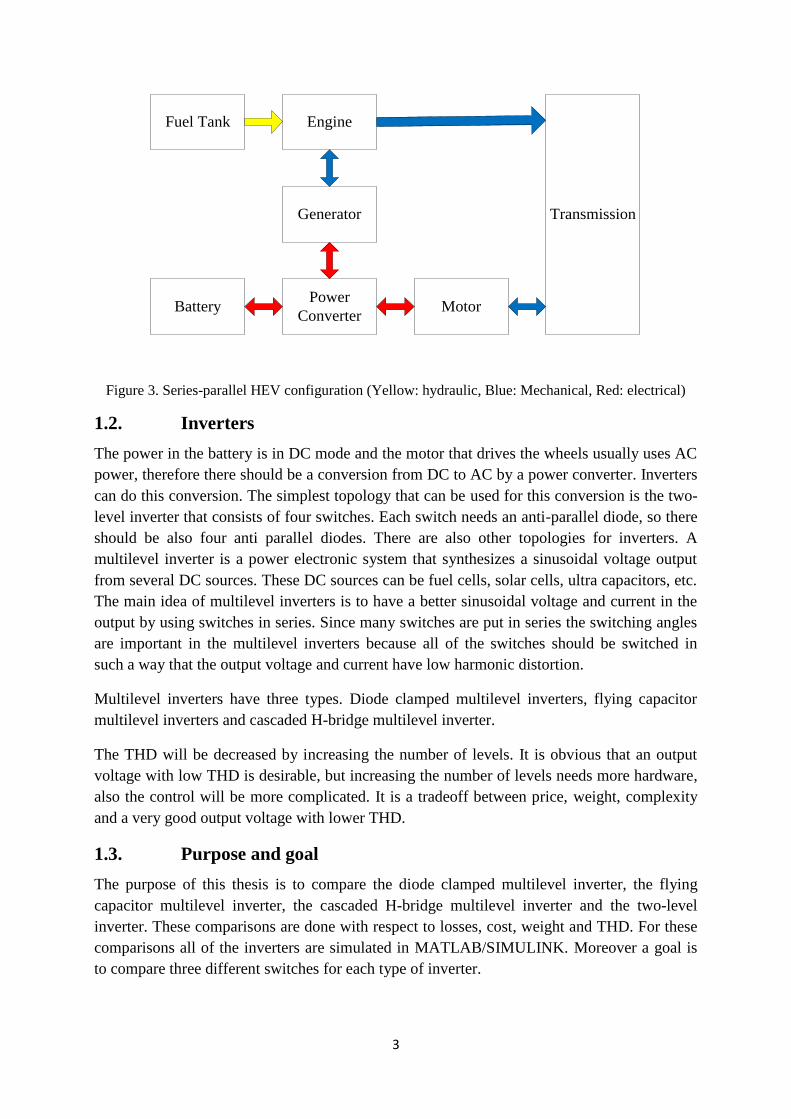
1.1.3. Series-parallel configuration
In this configuration, a generator is added between the engine and the power converter. The
control method in this configuration is more complicated than the series and the parallel
configurations. The operating modes in this configuration is divided in two groups, electric-
heavy where the electric motor is more active and engine-heavy where the internal
combustion engine is more active in the operation. The engine-heavy has six operation
modes: 1. Startup: In this mode the battery drives the wheels through the electric motor while
the internal combustion engine is off. 2. Acceleration: During the acceleration mode the
internal combustion engine and the electric motor run the wheels at the same time. 3. Normal
driving: The internal combustion engine drives the wheels while the electric motor is off. 4.
Deceleration: The electric motor charges the battery through the power converter. 5. Battery
charging in normal driving: In this mode the internal combustion engine should run the
wheels and the generator at the same time to charge the battery. 6. Battery charging: The
internal combustion engine charges the battery through the generator while the vehicle is in
full stop. The electric-heavy has also six operation modes: 1. Startup: In this mode the battery
drives the wheels through the electric motor while the internal combustion engine is off. 2.
Acceleration: The internal combustion engine and the battery drive the wheels. 3. Normal
driving: The internal combustion engine and the battery drive the wheels. 4. Deceleration: The
electric motor acts as a generator to charge the battery through the power converter. 5. Battery
charging in normal driving: The internal combustion engine should drive the wheels and the
generator at the same time to charge the battery. 6. Battery charging: The internal combustion
engine charges the battery through the generator and the power converter. Fig. 3 illustrates the
schematic of a series-parallel HEV configuration.
3
Fuel Tank
Power
Converter
Generator
MotorBattery
Engine
Transmission
Figure 3. Series-parallel HEV configuration (Yellow: hydraulic, Blue: Mechanical, Red: electrical)
1.2. Inverters
The power in the battery is in DC mode and the motor that drives the wheels usually uses AC
power, therefore there should be a conversion from DC to AC by a power converter. Inverters
can do this conversion. The simplest topology that can be used for this conversion is the two-
level inverter that consists of four switches. Each switch needs an anti-parallel diode, so there
should be also four anti parallel diodes. There are also other topologies for inverters. A
multilevel inverter is a power electronic system that synthesizes a sinusoidal voltage output
from several DC sources. These DC sources can be fuel cells, solar cells, ultra capacitors, etc.
The main idea of multilevel inverters is to have a better sinusoidal voltage and current in the
output by using switches in series. Since many switches are put in series the switching angles
are important in the multilevel inverters because all of the switches should be switched in
such a way that the output voltage and current have low harmonic distortion.
Multilevel inverters have three types. Diode clamped multilevel inverters, flying capacitor
multilevel inverters and cascaded H-bridge multilevel inverter.
The THD will be decreased by increasing the number of levels. It is obvious that an output
voltage with low THD is desirable, but increasing the number of levels needs more hardware,
also the control will be more complicated. It is a tradeoff between price, weight, complexity
and a very good output voltage with lower THD.
1.3. Purpose and goal
The purpose of this thesis is to compare the diode clamped multilevel inverter, the flying
capacitor multilevel inverter, the cascaded H-bridge multilevel inverter and the two-level
inverter. These comparisons are done with respect to losses, cost, weight and THD. For these
comparisons all of the inverters are simulated in MATLAB/SIMULINK. Moreover a goal is
to compare three different switches for each type of inverter.

4
1.4. Previous works
The previous works that has been done on the multilevel inverters are more focused on the
THD and the switching pattern of the multilevel inverters. Most of them are focused on to get
a better output voltage and current with lower THD by different switching patterns. Switching
angles in multilevel inverters are so important; since it can affect the output voltage and
current THD. There are many interesting works on calculating the switching angles to
eliminate the lowest order harmonics, such as “Active Harmonic Elimination for Multilevel
Converters” (Tolbert), which is a study of different harmonic elimination methods. The
newest method that uses for harmonic elimination is resultant theory. “Eliminating harmonics
in a multilevel converter using resultant theory” (Chiasson) is more focused on the resultant
theory for calculating the switching angles. There are also some works that are focused on
different usages of the multilevel inverters. There are some other works that are related to this
thesis that investigated different topologies of multilevel inverters for different electric
applications.”Multilevel converters for large electric drives” (Tolbert) compares the cascaded
H-bridge multilevel inverters with diode clamped multilevel inverters for large electric drives.

5
2. Multilevel inverters
Three types of multilevel inverter have been investigated in this thesis.
1. Diode Clamped multilevel inverters
2. Flying Capacitor multilevel inverters
3. Cascaded H-bridge multilevel inverters
2.1. Diode Clamped multilevel inverter
The main concept of this inverter is to use diodes to limit the power devices voltage stress.
The voltage over each capacitor and each switch is Vdc. An n level inverter needs (n-1)
voltage sources, 2(n-1) switching devices and (n-1) (n-2) diodes. 5-level diode clamped
multilevel inverter
2.1.1. 5-level diode clamped multilevel inverter
In a 5-level diode clamped multilevel:
n=5
Therefore:
Number of switches=2(n-1) =8
Number of diodes= (n-1) (n-2) =12
Number of capacitors= (n-1) =4
A 5-level diode clamped multilevel inverter is shown in Fig. 4. Switching states are shown in
Table.1. For example to have Vdc/2 in the output, switches S1 to S4 should conduct at the
same time. For each voltage level four switches should conduct. As it can be seen in Table.1
the maximum output voltage in the output is half of the DC source. It is a drawback of the
diode clamped multilevel inverter. This problem can be solved by using a two times voltage
source or cascading two diode clamped multilevel inverters. The output voltage of a 5-level
diode clamped multilevel inverter is shown in Fig.5. As can be seen in Fig.5 all of the voltage
level should have the same voltage value.
The switching angles should be calculated in such a way that the THD of the output voltage
becomes as low as possible. The switching angle calculation method that is used in this thesis
is the harmonic elimination method. In this method the lower dominant harmonics can be
eliminated by choosing calculated switching angles. This method will be explained later in
this thesis.

6
Table 1. The switching states of Diode clamped multilevel inverter.
V0 S1 S2 S3 S4 S5 S6 S7 S8
Vdc/2 1 1 1 1 0 0 0 0
Vdc/4 0 1 1 1 1 0 0 0
0 0 0 1 1 1 1 0 0
-Vdc/4 0 0 0 1 1 1 1 0
-Vdc/2 0 0 0 0 1 1 1 1
1S
2S
3S
4S
5S
6S
7S
8S
1C
2C
3C
4C
V
Figure 4. One phase of a diode clamped inverter

7
Figure 5. Output voltage of a 5-level multilevel inverter
2.1.2. 9-level diode clamped multilevel inverter
In this thesis a 9-level diode clamped inverter is made of two 5-level diode clamped inverters
which are cascaded. Therefore the number of switches, diodes and capacitors are two times
more than the 5-level diode clamped inverter. For a 9-level multilevel inverter:
n=9
Therefore:
Number of switches=2(n-1) =16
Number of diodes= (n-1) (n-2) =24
Number of capacitors= (n-1) =8
In this method switching angle should be calculated in such a way so that a 9-level output
voltage is produced. The output voltages of each 5-level diode clamped multilevel inverter are
added to each other, and then the output voltage is created. The output voltage of each diode
clamped multilevel inverter is shown in Fig.6 and Fig.7.
0 0.002 0.004 0.006 0.008 0.01 0.012 0.014 0.016 0.018 0.02-400
-300
-200
-100
0
100
200
300
400
time(seconds)
Voltage(V
)

8
Figure 6. Output voltage of the first cell
Figure 7. Output voltage of the second cell
0 0.002 0.004 0.006 0.008 0.01 0.012 0.014 0.016 0.018 0.02-200
-150
-100
-50
0
50
100
150
200
time(seconds)
Voltage(V
)
0 0.002 0.004 0.006 0.008 0.01 0.012 0.014 0.016 0.018 0.02-200
-150
-100
-50
0
50
100
150
200
time(seconds)
Voltage(V
)
9
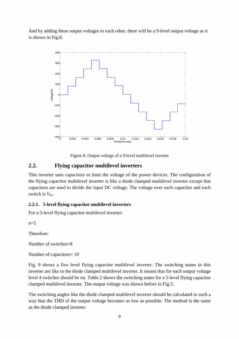
And by adding these output voltages to each other, there will be a 9-level output voltage as it
is shown in Fig.8.
Figure 8. Output voltage of a 9-level multilevel inverter
2.2. Flying capacitor multilevel inverters
This inverter uses capacitors to limit the voltage of the power devices. The configuration of
the flying capacitor multilevel inverter is like a diode clamped multilevel inverter except that
capacitors are used to divide the input DC voltage. The voltage over each capacitor and each
switch is Vdc.
2.2.1. 5-level flying capacitor multilevel inverters
For a 5-level flying capacitor multilevel inverter:
n=5
Therefore:
Number of switches=8
Number of capacitors= 10
Fig. 9 shows a five level flying capacitor multilevel inverter. The switching states in this
inverter are like in the diode clamped multilevel inverter. It means that for each output voltage
level 4 switches should be on. Table.2 shows the switching states for a 5-level flying capacitor
clamped multilevel inverter. The output voltage was shown before in Fig.5.
The switching angles like the diode clamped multilevel inverter should be calculated in such a
way that the THD of the output voltage becomes as low as possible. The method is the same
as the diode clamped inverter.
0 0.002 0.004 0.006 0.008 0.01 0.012 0.014 0.016 0.018 0.02-400
-300
-200
-100
0
100
200
300
400
time(seconds)
volta
ge(V
)

10
Table 2. The switching pattern for capacitor clamped multilevel inverter.
V0 S1 S2 S3 S4 S5 S6 S7 S8
Vdc/2 1 1 1 1 0 0 0 0
Vdc/4 1 1 1 0 1 0 0 0
0 1 1 0 0 1 1 0 0
-Vdc/4 1 0 0 0 1 1 1 0
-Vdc/2 0 0 0 0 1 1 1 1
1S
2S
3S
4S
5S
6S
7S
8S
1C
2C
3C
4C
V
cC
cC
cC
bC
bC
aC
Figure 9. One phase of a 5-level Flying capacitor multilevel inverter
2.2.2. 9-level flying capacitor multilevel inverter
For a 9-level multilevel inverter:
n=9
Therefore:
Number of capacitors=8
Number of switches=16
Like the diode clamped inverter in this thesis, a 9-level flying capacitor clamped inverter is
made of two 5-level flying capacitor inverters which are cascaded. Switching angles and
output voltage of each 5-level flying capacitor inverter are completely the same as for the 9-
level diode clamped inverter. The output voltage of each 5-level flying capacitor inverter was

11
shown before in Fig.6 and Fig.7. Those two output voltages are added to each other to make a
9-level output voltage which is shown in Fig.8.
2.3. Cascaded H-bridge multilevel inverter
The concept of this inverter is based on connecting H-bridge inverters in series to get a
sinusoidal voltage output. The output voltage is the sum of the voltage that is generated by
each cell. The number of output voltage levels are 2n+1, where n is the number of cells. The
switching angles can be chosen in such a way that the total harmonic distortion is minimized.
One of the advantages of this type of multilevel inverter is that it needs less number of
components comparative to the Diode clamped or the flying capacitor, so the price and the
weight of the inverter is less than that of the two former types. Fig. 10 shows an n level
cascaded H-bridge multilevel inverter. The switching angles calculation method that is used in
this inverter is the same as for the previous multilevel inverters.
An n level cascaded H-bridge multilevel inverter needs 2(n-1) switching devices where n is
the number of the output voltage level.
Vphase (Vo)
S11 S21
S31 S41
S1h S2h
S3h S4h
S12 S22
S32 S42
VDC
Module 1
Module 2
Module h
Vm1
0
VDC
VDC
Vm2
Vmh
Figure 10. One phase of a cascaded H-bridge multilevel inverter
2.3.1. 5-level Cascaded H-bridge multilevel inverter
The output voltage of this inverter has 5 levels like in the previous multilevel inverters. This
inverter consists of two H-bridge inverters that are cascaded. For a 5-level cascaded H-bridge
multilevel inverter 8 switching devices are needed.
12
2.3.2. 9-level cascaded H-bridge multilevel inverter
The output voltage of the multilevel level inverter has 9 levels the like the previous multilevel
inverters. This inverter consists of four H-bridge inverters that are cascaded. For a 9-level
cascaded H-bridge multilevel inverter 16 switching devices are needed.
2.4. Harmonic elimination method
The switching pattern that is used in this thesis for all of the multilevel inverters is harmonic
elimination method. In this method the switching angles for switches should be calculated in
such a way that the lower dominant harmonics are eliminated. In this case 5-level and 9-level
multilevel inverters will be investigated. For a 5-level inverter the 5th
harmonic will be
eliminated and for the 9-level inverter the 5th
, 7th
, 11th
harmonics will be eliminated. The
Fourier analysis needs to be calculated to determine the frequency spectra of the output
waveform.
2.4.1. 5-level multilevel inverters
The Fourier series of a 5-level unity DC source is shown in (2-1).
Where:
Vdc: Voltage of each voltage source that is unity
θi : The switching angles
h: The harmonic orders
From (2-1) four equations will be resulted for eliminating the harmonics 5th
.
Equations (2-2) and (2-3) are for the harmonics that should be eliminated, so (2-3) should be
equal to zero. The DC sources are constant, so

13
The modulation index is 1 since the voltage that is used in these calculations is in per unit.
From (2-2) to (2-5) the nonlinear equations will be calculated.
In this thesis equations are solved by the Newton-Raphson method.
In Newton-Raphson method the following matrixes should be created:
1. Switching angles matrix
2. The nonlinear system matrix
3. The answers matrix
For each iteration loop
By some iterations in MATLAB, the switching angles for a 5-level and 9-level cascaded H-
bridge multilevel inverter are calculated.
As can be seen in Fig.11 the 5th
harmonic was eliminated.

14
Figure 11. Output voltage harmonic spectrum for a 5-level multilevel inverter
2.4.2. 9-level multilevel inverters
The Fourier series of a 4 step unity DC source is shown in (2-8).
Where:
Vdc: Voltage of voltage sources for each cell that is unity
θi : The switching angle
h: The harmonic order
From (2-8) four equations will be resulted for eliminating the 5th
, 7th
, 11th
harmonics.
2 4 6 8 10 12 14 16 18 200
1
2
3
4
5
6
7
8
9
10
Harmonic order
Volta
ge (
% o
f F
undam
enta
l)

15
Equations (2-9) to (2-12) are for the harmonics that should be eliminated, so (2-10) to (2-12)
should be equal to zero. The DC sources are constant, so
The modulation index is 1 since the voltage that is used in these calculations is in per unit.
From equations (2-15) to (2-18) the nonlinear equations will be calculated.
For this method the following matrixes should be created:
1. Switching angles matrix
2. The nonlinear system matrix
3. The answers matrix

16
For each iteration loop
By some iteration in MATLAB, the switching angles for a 5-level and 9-level cascaded H-
bridge multilevel inverter are calculated.
As can be seen in Fig.12, 5th
, 7th
, 11th
harmonics of output voltage are eliminated.
Figure 12. Output voltage harmonic spectrum for a 9-level cascaded H-bridge multilevel inverter
2.5. Power Losses calculations
Power losses in all of the switching devices can be divided in three groups
1. Conduction losses
2. Switching losses
3. Blocking(leakage) losses that is normally being neglected
In this thesis two types of switches are used: IGBT and MOSFET. Power loss calculations for
the IGBT and the MOSFET are not done using the same method.
2 4 6 8 10 12 14 16 18 200
0.5
1
1.5
2
2.5
3
Harmonic order
Volta
ge (
% o
f F
undam
enta
l)

17
2.5.1. IGBT power losses calculations
The IGBT power losses like the other switching devices can be divided in three groups, but
leakages power losses are neglected.
2.5.1.1.Conduction losses
Conduction losses occur in the switches and in the anti parallel diodes. Conductions losses for
the switches can be calculated by (2-19) and the conduction losses for the anti parallel diode
can be calculated by (2-20):
where
uce0: on state zero current collector emitter voltage
Icav: average switch current
rc: collector emitter on-state resistance
Icrms: RMS switch current
uD0: diode approximation with a series conduction of DC voltage sources
IDav: average diode current
rD: diode on-state resistance
IDrms: RMS diode current
uce0 and rc can be obtained from the diagram collector-emitter voltage versus collector current
in the datasheet.
uD0 and rD can be obtained from the diagram forward voltage versus forward current in the
datasheet.
2.5.1.2.Switching losses
Switching losses are created in the switches and in the anti parallel diodes. Switching losses
for the switch can be calculated by (2-21) and switching losses for the anti parallel diode can
be calculated by (2-22).
where
EonI: turn on energy losses in IGBT

18
EoffI: turn off energy losses in IGBT
EonD: turn on energy losses in diode
EoffD: turn off energy losses in diode that normally is being neglected
fsw: switching frequency
EonI, EoffI, EonD can be obtained from the datasheet of each IGBT.
2.5.2. MOSFET power losses calculations
The Mosfet power losses can as for the other switching devices can be divided in three groups
when leakage power losses are neglected.
2.5.2.1.Conduction losses
Like in the IGBT, conductions losses are in the switches and in the anti parallel diodes.
Conduction losses for the switch can be calculated by (2-23) and conduction losses for anti
parallel diode can be calculated by (2-24).
where
RDSon: drain-source on-state resistance
IMrms: RMS value of the MOSFET on-state current
uD0: diode approximation with a series conduction of DC voltage sources
IDav: average diode current
RD: diode on-state resistance
IDrms: RMS diode current
RDSon should be obtained from the datasheet. uD0 and RD should be obtained from the diagram
“Forward character of reverse diode” in the datasheet.
2.5.2.2. Switching losses
Switching losses include switch-on transient and switch-off transient. Energy losses for on-
transient can be calculated by (2-26) and energy losses for off transient can be calculated by
(2-27). Total switching losses can be calculated by (2-25).

19
where
VDD: Voltage across the MOSFET
IDon,IDoff : The current passing through MOSFET during on-time or off-time
Tri: Current rise time
Tfi: Current fall time
Trv: Voltage rise time
Tfv: Voltage fall time
CGD: Gate-Drain capacitor
V (plateau): Gate plateau voltage
RG: Gate resistance that is depends on the drive circuit of the MOSFET
If VDS is between 0, VDD/2 the gate-drain capacitance will be CGD (RDSon.Ion) = CGD1. If VDS is
between VDD/2, VDD the gate-drain capacitance will be CGD (VDD) = CGD2.
VDD, IDon, IDoff should be measured. tri, tfi, CGD, RG, V(plateau) values should be found in the
MOSFET datasheet.

20
3. Comparison between a 5-level diode clamped, flying capacitor,
H-bridge and two-level inverters on Power losses, cost, weight
and THD
In these simulations a balanced three phase system is assumed. The load for the system is a
three phase asynchronous motor. The parameters of the asynchronous motor are listed below:
Nominal power = 75 KW
Line-line RMS voltage = 400 V
Frequency = 50 Hz
Rotor nominal speed = 1484 rpm
Stator resistance = 0.03552 Ω
Stator inductance = 0.335 mH
Rotor resistance = 0.02092 Ω
Rotor inductance = 0.335 mH
Mutual inductance = 15.1 mH
Pole pairs = 2
In this thesis three different IGBTs and one MOSFET and one diode and one capacitor were
used. Characteristics for all of the devices are as follows:
IGBT FD300R06KE3
Collector-Emitter voltage= 600 V
DC-collector current= 300 A
Repetitive peak reverse voltage= 600 V
DC forward current= 300 A
uCE0= 0.85 V
rc=0.0022 Ω
uD0=0.9 V
rD=0.0014 Ω
Weight=340 g
Price: 132.48 €

21
IGBT FF200R12KE4
Collector-Emitter voltage= 1200 V
DC-collector current= 200 A
Repetitive peak reverse voltage= 1200 V
DC forward current= 200 A
uCE0=0.8 V
rc=0.0054 Ω
uD0=1 V
rD=0.0033 Ω
Weight=340 g
Price: 138.86 €
IGBT FMG2G300US60
Collector-Emitter voltage= 600 V
DC-collector current= 300 A
Repetitive peak reverse voltage= 600 V
DC forward current= 300 A
uCE0=1.5 V
rc=0.0029 Ω
uD0=1.1 V
rD=0.0027 Ω
Weight=360 g
Price: 117.7 €
MOSFET STE250NS10
Drain-Source voltage=100 V
Drain current (continuous) = 156 A
Drain current (pulse) = 880 A
RDSon=0.0055 Ω

22
uD0=0.9 V
rD=0.0029 Ω
Weight=9 g
Price: 31.61 €
Diode 85HF60
Forward average current= 85 A
Maximum repetitive peak reverse voltage= 600 V
uD0=0.7 V
rD=0.0015 Ω
Weight=17 g
Price: 6.33 €
Capacitor FFV34E0107K
Nominal capacitance= 100 µF
Rated voltage= 100V DC
ESR, DC= 0.55 mΩ
Maximum RMS current= 24 A
Weight= 0.09 Kg
Price: 25.01 €
Capacitor C4DEFPQ6380A8TK
Nominal capacitance= 380 µF
Rated voltage= 400V DC
ESR, DC= 0.81 mΩ
Maximum RMS current= 100 A
Weight= 0.419 Kg
Price: 90.49 €

23
3.1. Power Losses comparison between 5-level diode clamped, 5-level
capacitor clamped, 5-level cascaded H-bridge and two-level inverters
3.1.1. Loss calculations for IGBT FD300R06KE3
When the motor is operating in full load, the RMS and the average current that is passing
through the diodes and switches are obtained from the SIMULINK file.
3.1.1.1.5-level Diode clamped multilevel inverter
The RMS current that is passing through one of the switches is 48.19A and the average
current that is passing through one of the switches is 15.99A.
IIav=15.99A
IIRMS=48.19A
No current passes through the anti parallel diodes in full load, so the conduction losses of anti
parallel diodes are equal to zero.
According to (2-19) and for one switch, the power losses are:
PcI= 17.7982W
There are 24 switches for three phases so:
PcI=427.1566W
For the diode clamped multilevel inverter, the diode power losses should be calculated by (2-
20). The power losses for one diode are:
PcD= 7.0697W
There are 36 diodes in the 5-level diode clamped multilevel inverter, so the total power losses
are:
PcD= 254.5108W
Since the switching frequency is 50Hz, the switching losses are neglected in this thesis.
3.1.1.2.5-level flying capacitor multilevel inverter
The RMS current that is passing through one of the switches is 49.02A and the average
current that is passing through one of the switches is 17.28A.
IIav=17.28A
IIRMS=49.02A
No current passes through anti parallel diodes in full load, so the conduction losses of anti
parallel diodes are equal to zero.
According to (2-19) and for one switch, the power losses are:

24
PcI= 19.1105W
There are 24 switches for three phases so:
PcI=458.6523W
3.1.1.3.5-level cascaded H-bridge multilevel inverter
There are 8 switches in each cell, but the current that passes through the switches is not the
same for all of them. There are four different currents. It means that in each cell two switches
have same current value. The values for full load are presented in Table.3.
Table 3. Currents that pass through different switches
Switches IGBT RMS(A) IGBT average(A) Diode RMS(A) Diode average(A)
S11,S21 91 54.3 7.29 1.1
S31,S41 93.2 58.9 21.5 5.6
S12,S22 79 37.8 0 0
S32,S42 93.5 60 50 22.1
According to (2-19) and (2-20) the power losses are:
PcI= 1491.2W
PcD= 209.3593W
PcTot=1700.6W
3.1.1.4.Two-level inverter
There are 4 switches in each cell in one level inverter and the current that passes through each
switch is the same for all of the switches.
IIav=63.56A
IIRMS=100.7A
IDav=5.322A
IDRMS=28.93A
According to (2-19) and (2-20) power losses are:
PcI= 952.5267W
PcD= 78.6561W
PcTot=1031.2W
Fig.13 shows the power loss comparison when using IGBT FD300R06KE3.
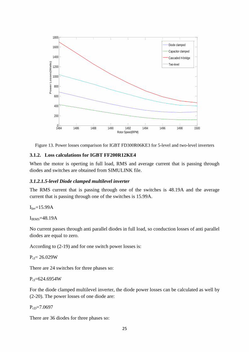
25
Figure 13. Power losses comparison for IGBT FD300R06KE3 for 5-level and two-level inverters
3.1.2. Loss calculations for IGBT FF200R12KE4
When the motor is operting in full load, RMS and average current that is passing through
diodes and switches are obtained from SIMULINK file.
3.1.2.1.5-level Diode clamped multilevel inverter
The RMS current that is passing through one of the switches is 48.19A and the average
current that is passing through one of the switches is 15.99A.
IIav=15.99A
IIRMS=48.19A
No current passes through anti parallel diodes in full load, so conduction losses of anti parallel
diodes are equal to zero.
According to (2-19) and for one switch power losses is:
PcI= 26.029W
There are 24 switches for three phases so:
PcI=624.6954W
For the diode clamped multilevel inverter, the diode power losses can be calculated as well by
(2-20). The power losses of one diode are:
PcD=7.0697
There are 36 diodes for three phases so:
1484 1486 1488 1490 1492 1494 1496 1498 15000
200
400
600
800
1000
1200
1400
1600
1800
Rotor Speed(RPM)
Po
we
r L
osse
s(W
atts)
Diode clamped
Capacitor clamped
Cascaded H-bridge
Two-level

26
PcD=254.5108
Since the switching frequency is 50Hz, the switching power losses are neglected in this thesis.
3.1.2.2.5-level flying capacitor clamped multilevel inverter
The RMS current that is passing through one of the switches is 49.02A and the average
current that is passing through one of the switches is 17.28A.
IIav=17.28A
IIRMS=49.02A
No current passes through the anti parallel diodes in full load, so the conduction losses of the
anti parallel diodes are equal to zero.
According to (2-19) and for one switch, the power losses are:
PcI= 27.5209W
There are 24 switches for three phases so:
PcI=660.5010W
3.1.2.3.5-level cascaded H-bridge multilevel inverter
There are 8 switches in each cell, but the current that passes through the switches is not the
same for all of them. There are four different currents. It means that in each cell two switches
have same current value. Values for full load are given in Table.4.
Table 4. Currents that pass through different switches
Switches IGBT RMS(A) IGBT average(A) Diode RMS(A) Diode average(A)
S11,S21 91 54.3 7.3 1.1
S31,S41 93.2 58.9 21.5 5.6
S12,S22 79 37.8 0 0
S32,S42 93.5 59.9 50 22.1
The RMS current that is passing through one of the switches is 48.19A and the average
current that is passing through one of the switches is 15.99A.
According to (2-19) and (2-20) power losses are:
PcI= 1920.3W
PcD= 242.3127W
PcTot=2162.6W
No current passes through the anti parallel diodes in full load, so the conduction losses of the
anti parallel diodes are equal to zero.

27
According to (2-19) the power losses are:
PcI= 1700.6W
3.1.2.4.Two-level inverter
There are 4 switches in each cell in the two-level inverter and the current that passes through
each switch is the same for all of the switches.
IIav=63.56A
IIRMS=100.7A
IDav=5.322A
IDRMS=28.93A
According to (2-19) and (2-20), the power losses are:
PcI= 1376.8W
PcD= 96.63W
PcTot=1473.4W
Fig.14 shows the power losses comparison for IGBT FF200R12KE4.
Figure 14. Power losses comparison for IGBT FF200R12KE4 for 5-level and two-level inverters
3.1.3. Loss calculations for IGBT FF200R12KE4
The power losses can be calculated like for the previous switches.
Fig.15 shows the power losses comparison for IGBT FMG2G300US60.
1484 1486 1488 1490 1492 1494 1496 1498 15000
500
1000
1500
2000
2500
Rotor Speed(RPM)
Po
we
r L
osse
s(W
atts)
Diode Clamped
Capacitor Clamped
Cascaded H-bridge
Two-level

28
Figure 15. Power losses comparison for IGBT FMG2G300US60 for 5-level and two-level inverters
3.2. Power losses comparison between 9-level diode clamped
multilevel inverter, 9-level flying capacitor clamped multilevel inverter
and 9-level cascaded H-bridge multilevel inverter
The loss calculations method is like performed in (3-1), that current was obtained from the
SIMULINK file and the data of switches were obtained from datasheets. By using the power
losses calculations formulas, the power losses are calculated.
In this comparison two different IGBTs and one MOSFET were used.
3.2.1. Loss calculations for IGBT FD300R06KE3
When the motor is operating in full load, the RMS and the average current that is passing
through the diodes and the switches are obtained from the SIMULINK file.
3.2.1.1.9-level Diode clamped multilevel inverter
As stated before in this thesis the 9-level diode clamped multilevel inverter are made by
cascading two 5-level diode clamped multilevel inverters which are cascaded but their
switching angles are different from each other. The RMS and the average current that is
passing through one of the switches are 62.17A and 33.2A.
IIav=33.2A
IIRMS=62.17A
No current passes through the anti parallel diodes in full load, so the conduction losses of the
anti parallel diodes are equal to zero.
According to (2-19) and (2-20) the power losses for one of the switches is:
PcI= 35.95W
1484 1486 1488 1490 1492 1494 1496 1498 15000
500
1000
1500
2000
2500
3000
3500
Rotor Speed(RPM)
Po
we
r L
osse
s(W
atts)
Diode Clamped
Capacitor Clamped
Cascaded H-bridge
Two-level

29
There are 48 switches for three phases so:
PcI=1725.4W
For the diode clamped multilevel inverter, the diode power losses should be calculated as
well. There are 24 diodes for a 9-level diode clamped inverter that conduction losses for one
of them are calculated by (2-20).
For full load PcD= 490.0986W
Since the switching frequency is 50Hz, switching losses are neglected in this thesis.
3.2.1.2.9-level flying capacitor multilevel inverter
The RMS current that is passing through one of the switches is 61.15A and the average
current that is passing through one of the switches is 32.1A.
IIav=32.1A
IIRMS=61.15A
No current passes through the anti parallel diodes in full load, so the conduction losses of the
anti parallel diodes are equal to zero.
According to (2-19) and for one switch power losses is:
PcI= 35.46W
There are 48 switches for three phases so:
PcI=1702.3W
3.2.1.3.9-level cascaded H-bridge multilevel inverter
There are 16 switches in each cell, but the current that passes through the switches is not the
same for all of them. There are four different currents. It means that in each cell two switches
have the same current value. The current values for full load are given in Table.5.
Table 5. Currents that pass through different switches
Switches IGBT RMS(A) IGBT average(A) Diode RMS(A) Diode average(A)
S11,S21 81.66 47.89 6.826 1.321
S31,S41 84.19 52.3 19.93 5.731
S12,S22 79.37 44.65 2.299 0.2649
S32,S42 84.44 53.35 27.66 8.963
S13,S23 73.72 37.74 0 0
S33,S43 84.47 53.62 40.39 15.88
S14,S24 61.24 24.76 0 0
S34,S44 84.47 53.62 57.58 28.85

30
According to (2-19) and (2-20) power losses are:
PcI= 2498.2W
PcD= 407.0097W
PcTot=2905.2W
Fig.17 shows the power losses comparison for IGBT FD300R06KE3.
Figure 17. Power losses comparison for IGBT FD300R06KE3 for the 9-level inverters
3.2.2. Loss calculations for IGBT FF200R06KE4
When the motor is operating in full load, the RMS and the average current that is passing
through the diodes and the switches are obtained from the SIMULINK file.
3.2.2.1.9-level Diode clamped multilevel inverter
As stated before in this thesis the 9-level diode clamped multilevel inverter are made by
cascading two 5-level diode clamped multilevel inverters which are cascaded but their
switching angles are different from each other. The RMS and the average current that is
passing through one of the switches are 62.17A and 33.2A.
IIav=33.2A
IIRMS=62.17A
No current passes through anti parallel diodes in full load, so the conduction losses of the anti
parallel diodes are equal to zero.
According to (2-19) and for one switch power losses is:
1484 1486 1488 1490 1492 1494 1496 1498 15000
500
1000
1500
2000
2500
3000
Rotor Speed(RPM)
Po
we
r L
osse
s(W
atts)
Diode Clamped
Capacitor Clamped
Cascaded H-brdige

31
PcI= 51.525W
There are 48 switches for three phases so:
PcI=2473.2W
For the diode clamped multilevel inverter, the diode power losses should be calculated by (2-
20). The power losses for one diode are:
PcD=6.8069
There are 72 diodes in the 9-level diode clamped multilevel inverter, so the total power losses
will be:
PcD= 490.0986W
Since switching frequency is 50Hz, switching losses are neglected in this thesis.
3.2.2.2.9-level flying capacitor multilevel inverter
The RMS current that is passing through one of the switches is 61.15A and the average
current that is passing through one of the switches is 32.1A.
IIav=32.1A
IIRMS=61.15A
No current passes through the anti parallel diodes in full load, so the conduction losses of the
anti parallel diodes are equal to zero.
According to (2-19) and for one switch, the power losses are:
PcI= 50.9W
There are 48 switches for three phases so:
PcI=2443W
3.2.2.3.5-level cascaded H-bridge multilevel inverter
There are 8 switches in each cell, but the current that passes through the switches is not the
same for all of them. There are four different currents. It means that in each cell two switches
have the same current value. The values for full load are presented in Table.6.

32
Table 6. Currents that pass through different switches
Switches IGBT RMS(A) IGBT average(A) Diode RMS(A) Diode average(A)
S11,S21 81.66 47.89 6.826 1.321
S31,S41 84.19 52.3 19.93 5.731
S12,S22 79.37 44.65 2.299 0.2649
S32,S42 84.44 53.35 27.66 8.963
S13,S23 73.72 37.74 0 0
S33,S43 84.47 53.62 40.39 15.88
S14,S24 61.24 24.76 0 0
S34,S44 84.47 53.62 57.58 28.85
According to (2-19) and (2-20), the power losses are:
PcI= 3213.4W
PcD= 535.5721W
PcTot=3748.9W
Fig. 18 shows the power losses comparison between the three different inverters for IGBT
FF200R12KE4.
Figure 18. Power losses comparison for IGBT FF200R12KE4 for the 9-level inverters
3.2.3. Power Losses calculations for Mosfet STE250NS10
When the motor is operating in full load, the RMS and the average current that is passing
through the diodes and the switches are obtained from the SIMULINK file.
The RDSon in the Mosfet is slightly alternated with temperature and the current that is passing
through the Mosfet. The Mosfet STE250NS10 “Static drain-source on resistance” diagram
which is in the data sheet of the Mosfet shows that in the current range that the Mosfet
1484 1486 1488 1490 1492 1494 1496 1498 15000
500
1000
1500
2000
2500
3000
3500
4000
Rotor Speed(RPM)
Po
we
r L
osse
s(W
atts)
Diode Clamped
Capacitor Clamped
Cascaded H-bridge

33
operates, the variations of RDSon are small. These variations are neglected in this thesis, so in
this case it is assumed that RDSon does not change during the simulations.
3.2.3.1.9-level Diode clamped multilevel inverter
As stated before in this thesis the 9-level diode clamped multilevel inverter are made by
cascading two 5-level diode clamped multilevel inverters which are cascaded but their
switching angles are different from each other. The RMS and the average current that is
passing through one of the switches is 62.17A and 33.2A.
IIav=33.2A
IIRMS=62.17A
No current passes through the anti parallel diodes in full load, so the conduction losses of the
anti parallel diodes are equal to zero.
According to (2-23) and for one switch, the power losses are:
PcI= 10.63W
There are 48 switches for three phases so:
PcI=510.1944W
For the diode clamped multilevel inverter, the diode power losses should be calculated by (2-
24). The power losses of one diode are:
PcD= 6.8069W
There are 72 diodes in the 9-level diode clamped multilevel inverter, so the total power losses
will be:
For full load PcD= 490.0986W
Since the switching frequency is 50Hz, the switching power losses are neglected in this thesis.
3.2.3.2.9-level flying capacitor multilevel inverter
The RMS current that is passing through one of the switches is 61.15A and the average
current that is passing through one of the switches is 32.1A.
IIav=32.1A
IIRMS=61.15A
No current passes through the anti parallel diodes in full load, so the conduction losses of the
anti parallel diodes are equal to zero.
According to (2-23) and for one switch power losses is:
PcI= 10.52W

34
There are 48 switches for three phases so:
PcI=505.23W
3.2.3.3.9-level cascaded H-bridge multilevel inverter
There are 8 switches in each cell, but the current that passes through switches is not the same
for all of them. There are four different currents. It means that in each cell two switches have
the same current value. Values for full load are given in Table.7.
Table 7. Currents that pass through different switches
Switches IGBT RMS(A) IGBT average(A) Diode RMS(A) Diode average(A)
S11,S21 81.66 47.89 6.826 1.321
S31,S41 84.19 52.3 19.93 5.731
S12,S22 79.37 44.65 2.299 0.2649
S32,S42 84.44 53.35 27.66 8.963
S13,S23 73.72 37.74 0 0
S33,S43 84.47 53.62 40.39 15.88
S14,S24 61.24 24.76 0 0
S34,S44 84.47 53.62 57.58 28.85
According to (2-23) and (2-24) power losses are:
PcI= 1671.2W
PcD= 367.14W
PcTot=2038.3W
Fig. 19 shows the power losses comparison between the three different inverters for MOSFET
STE250NS10.
Figure 19. Power losses comparison for MOSFET STE250NS10 for the 9-level inverters
1484 1486 1488 1490 1492 1494 1496 1498 15000
500
1000
1500
2000
2500
Rotor Speed(RPM)
Po
we
r L
osse
s(W
atts)
Diode Clamped
Capacitor Clamped
Cascaded H-bridge
35
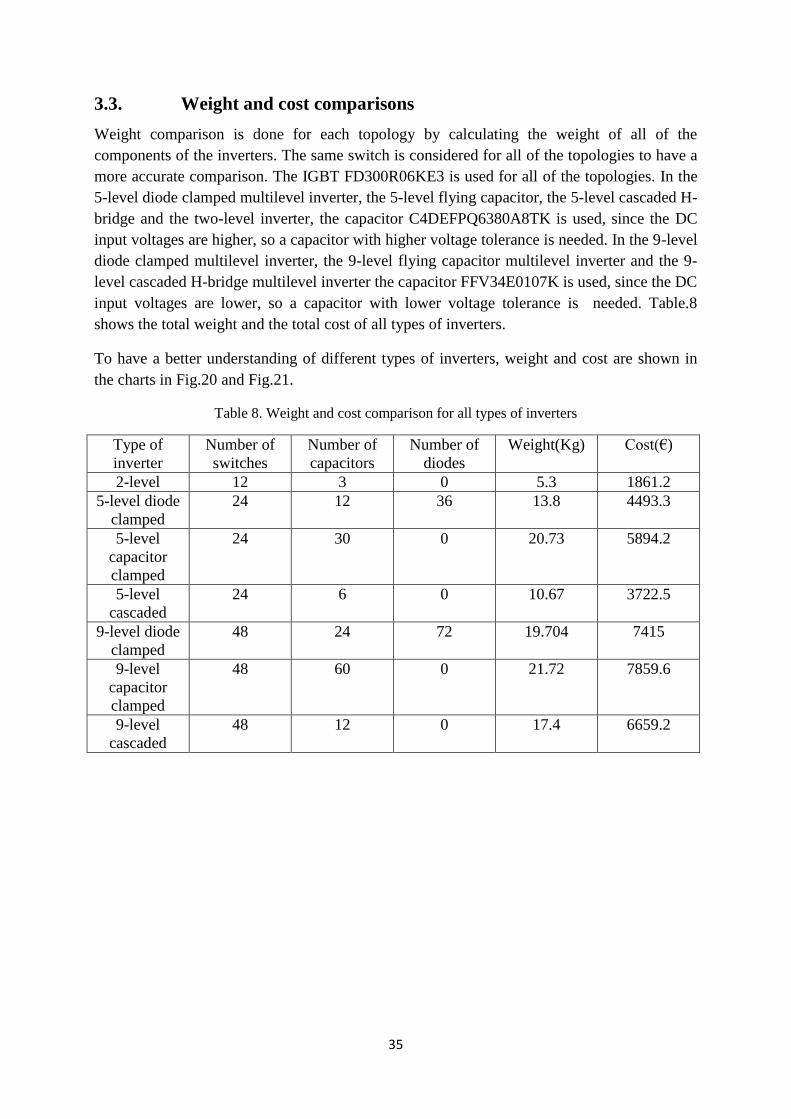
3.3. Weight and cost comparisons
Weight comparison is done for each topology by calculating the weight of all of the
components of the inverters. The same switch is considered for all of the topologies to have a
more accurate comparison. The IGBT FD300R06KE3 is used for all of the topologies. In the
5-level diode clamped multilevel inverter, the 5-level flying capacitor, the 5-level cascaded H-
bridge and the two-level inverter, the capacitor C4DEFPQ6380A8TK is used, since the DC
input voltages are higher, so a capacitor with higher voltage tolerance is needed. In the 9-level
diode clamped multilevel inverter, the 9-level flying capacitor multilevel inverter and the 9-
level cascaded H-bridge multilevel inverter the capacitor FFV34E0107K is used, since the DC
input voltages are lower, so a capacitor with lower voltage tolerance is needed. Table.8
shows the total weight and the total cost of all types of inverters.
To have a better understanding of different types of inverters, weight and cost are shown in
the charts in Fig.20 and Fig.21.
Table 8. Weight and cost comparison for all types of inverters
Type of
inverter
Number of
switches
Number of
capacitors
Number of
diodes
Weight(Kg) Cost(€)
2-level 12 3 0 5.3 1861.2
5-level diode
clamped
24 12 36 13.8 4493.3
5-level
capacitor
clamped
24 30 0 20.73 5894.2
5-level
cascaded
24 6 0 10.67 3722.5
9-level diode
clamped
48 24 72 19.704 7415
9-level
capacitor
clamped
48 60 0 21.72 7859.6
9-level
cascaded
48 12 0 17.4 6659.2

36
Figure 20. Weight comparison for all topologies of inverters
Figure 21. Cost comparison for all topologies of inverter
3.4. THD comparison for all of the inverter topologies
THD calculations obtained from the SIMULINK file. All of the THDs are for stator current in
the electrical motor. The THD comparison between the 5-level inverters, the 9-level inverters
and the two-level inverters is shown in Fig.22. The output voltage of all the 5-level topologies
is the same, since the same switching pattern is used for all of them. The output voltage of all
the 9-level inverters is the same, since the same switching pattern is used for all of them.
0
5
10
15
20
25
We
igh
t(K
g)
Two-level inverter
Diode Clamped 5-level
Capacitor Clamped 5-level
Cascaded H-brdige 5-level
Diode Clamped 9-level
Capacitor Clamped 9-level
Cascaded H-brdige 9-level
0
1000
2000
3000
4000
5000
6000
7000
8000
9000
Pri
ce(E
uro
)
Two-level inverter
Diode Clamped 5-level
Capacitor Clamped 5-level
Cascaded H-bridge 5-level
Diode Clamped 9-level
Capacitor Clamped 9-level
Cascaded H-bridge 9-level

37
Figure 22. Voltage THD comparison for all inverter topologies
0
5
10
15
20
25
30
35
40
45
THD
(%
) vo
ltag
e
Two-level
5-level inverters
9-level inverters

38
4. Conclusions
The choice of topology for each inverter should be based on what is the usage of the inverter.
Each topology has some advantages and disadvantages. By increasing the number of levels,
the THD will be decreased but on the other hand cost and weight will be increased as well.
Also since the switching angles for switches are not the same, the drive circuit for each switch
is separate from other switches.
The two-level inverter has the lowest cost and weight in comparison with the other topologies.
But this inverter has a very high THD; its THD is about 40% when one switching event for
fundamental period is used. In weight and cost calculations, the price and weight of the filter
should be considered, since it is not practical to have an output voltage with 40% THD. The
cost and the weight of the 5-level multilevel inverters seem better than the 9-level multilevel
inverters. By increasing the number of levels, the cost and weight of the multilevel inverter
will be increased. The advantage that the 9-level multilevel inverters have over the 5-level
multilevel inverters is their THD before filters, thus a filter will be needed. The 9-level
multilevel inverters have lower THD than the 5-level multilevel inverters. For example the
THD in the 5-level multilevel inverters and the 9-level inverters are 15% and 7%. It seems
that using the 5-level inverter and a filter is a better design.
The Flying capacitor clamped inverter has the lowest power losses between all of the other
topologies, since there is no diode in its topology. For example the power losses in the 5-level
flying capacitor multilevel inverter in full load are 625W, but it has two big problems. First is
that it is heavier than the other topologies. It is not practical to use this heavy inverter in
applications that are going to be used in applications that are not stable. Also the cost of this
inverter is more than other inverters. It seems that the flying capacitor clamped multilevel
inverter can be used in applications where the power losses are more important compared to
the weight and cost.
The cascaded H-bridge has the lowest weight and cost between the multilevel inverters, but its
power losses is more that all the other topologies. For example at compared to the other
topologies its power loss is 3749W. This topology can be used in applications where the
weight and the cost of the application is more important than its power losses.
The diode clamped multilevel inverter’s power losses are lower than cascaded H-bridge. For
example the power losses in the 9-level diode clamped multilevel inverter are 2963W. The
diodes that were used in this thesis cost 6.95 Euros, so the cost will not be that much higher
than the cascaded H-bridge. It seems that diode clamped inverter is a topology between all
other topologies that THD, cost and power losses are between other types of inverters.

39
References
[1] Muhammad H. Rashid, Power Electronics circuits, devices, and applications. 2004 by
Pearson education Inc.
[2] Zhong Du, Leon M. Tolber, Burak Ozpineci, John N. Chiasso, DC-AC Cascaded H-
Bridge Multilevel Boost Inverter With No Inductors for Electric/Hybrid Electric Vehicle
Applications. 2009, Boise state university
[3] Martin Veenstra, INVESTIGATION AND CONTROL OF A HYBRID ASYMMETRIC
MULTI-LEVEL INVERTER FOR MEDIUM-VOLTAGE APPLICATIONS, 2003,
Lausanne, EPFL
[4] L.M. Tolbert, F.Z. Peng, D.J. Adams, J.W. Mckeever, Multilevel inverters for large
automotive electric drives, 1997, Darborn, Michigan
[5] K.T. Chau, Y.S. Wong, Overview of power management in hybrid electric vehicles, 2002,
Energy conversion and management 43
[6] Chris Mi, Fang. Z. Peng, Kenneth J. Kelly, Michael O’Keefe, Vahab Hassani, Topology,
design, analysis and thermal management of power electronics for hybrid electric vehicle
applications, International journal of Electric and Hybrid vehicles, Vol.1, 2008
[7] Fang Z. Peng, A Generalized Multilevel Inverter Topology with Self Voltage Balancing,
IEEE transaction on Industry applications, Vol. 37, 2001
[8] Leon M. Tolbert, John Chiasson, Keith McKenzie, Zhong Du, Elimination of harmonics
in a multilevel converter with non equal DC sources, IEEE transaction on Industry
applications, Vol.41, 2005
[9] José Rodríguez, Jih-Sheng Lai, Fang Zheng Peng, Multilevel Inverters: A Survey of
Topologies, Controls and Applications, IEEE transaction on Industry Electronics, Vol.49,
2002
[10] Leon M. Tolbert, Fang Z. Peng, Multilevel Converters as a Utility Interface for
Renewable Energy Systems, Power engineering society summer meeting, 2000, IEEE
[11] Leon M. Tolbert, Fang Zheng Peng, Tim Cunnyngham, John N. Chiasson, Charge
balance control schemes for cascade multilevel converter in hybrid electric vehicles, IEEE
transactions on industrial electronics, Vol.49, 2002
[12] John N. Chiasson, Leon M. Tolbert, Keith J. McKenzie, Zhong Du, Control of a
multilevel inverter using resultant theory, IEEE transaction on control systems technology,
Vol.11, 2003
[13] D. Grahame Holmes, Thomas A.Lipo, Pulse width modulation for power converters,
2003 by Wiley interscience Inc.