medium voltage products pr521 manuale operativo per · pdf filemedium voltage products pr521...
TRANSCRIPT

Medium Voltage Products
PR521Manuale operativo per unità di protezione a microprocessoreOperator manual for microprocessor based protection unit
Index
Introduction 5
1. Packing and transport 5
2. Checking on receipt 5
3. Storage 6
4. Description 7
5. Installation of the PR521 unit 9
6. Programming the PR521 unit 10
7. Putting into service 29
8. Periodic checks 29
9. Spare parts and accessories 30
10. Time current curves 31
11. Wiring diagrams 38
12. PR512 unit connections 39
Indice
Premessa 5
1. Imballaggio e trasporto 5
2. Controllo al ricevimento 5
3. Magazzinaggio 6
4. Descrizione 7
5. Installazione dell’unità PR521 9
6. Programmazione dell’unità PR521 10
7. Messa in servizio 29
8. Controlli periodici 29
9. Parti di ricambio e accessori 30
10. Curve tempo corrente 31
11. Schema di collegamento 38
12. Connessione dell’unità PR521 39


647008/002 - 2000/05 it-en - 1/40
!
!
Responsible behaviour safeguardsyour own and others’ safety!
For any requests, please contactABB Assistance Service.
!
!
Un comportamento responsabilesalvaguarda la vostra e l’altrui sicurezza!
Per qualsiasi esigenza contattareil Servizio Assistenza ABB.
For your safety!
� Check that the installation room (spaces, segregationsand ambient) are suitable for the electrical and elec-tronic apparatus.
� Make sure that all the installation, putting into serviceand maintenance operations are carried out by suit-ably qualified personnel with adequate knowledge ofthe apparatus.
� Make sure that the Standard and Legal requirementsare followed during installation, service and mainte-nance, in order to construct installations according togood technical and safety working practices.
� Strictly follow all the information given in this instruc-tion manual.
� Check that the rated performance of the apparatus isnot exceeded during service.
� Pay particular attention to the notes indicated in themanual by the following symbol:
� Check that the personnel operating the apparatushave this instruction manual to hand, as well as thenecessary information for correct intervention.
� Only use original spare parts.
Disconnect the PR521 unit before carrying out anyinsulation tests on the installation.
Per la vostra sicurezza!
� Verificare che il locale di installazione (spazi, segrega-zioni e ambiente) sia idoneo per l’apparecchiaturaelettrica ed elettronica.
� Verificare che tutte le operazioni di installazione, mes-sa in servizio e manutenzione siano effettuate da per-sonale con una qualifica sufficiente e una conoscenzaadeguata della apparecchiatura.
� Verificare che durante le fasi di installazione, esercizioe manutenzione vengano rispettate le prescrizioniNormative e di Legge, per l’esecuzione degli impiantisecondo le regole della buona tecnica e di sicurezzasul lavoro.
� Osservare scrupolosamente le informazioni riportatenel presente manuale d’uso.
� Verificare che durante il servizio non vengano supera-te le prestazioni nominali dell’apparecchiatura.
� Prestare particolare attenzione alle note indicate nelmanuale dal seguente simbolo:
� Assicurarsi che il personale operante sull’apparec-chiatura abbia a disposizione il presente manualed’uso e le informazioni necessarie ad un correttointervento.
� Utilizzare solo parti di ricambio originali.
Scollegare l’unità PR521 prima di effettuare qualsiasiprova di isolamento sull’impianto.

2/40 - 647008/002 - 2000/05 it-en

647008/002 - 2000/05 it-en - 3/40
Index
Introduction 5
1. Packing and transport 5
2. Checking on receipt 5
3. Storage 6
4. Description 7
4.1. General 7
4.2. Reference Standards 7
4.3. Ambient conditions 7
4.4. Technical data 8
5. Installation of the PR521 unit 9
5.1. Connection to the auxiliary circuits 9
6. Programming the PR521 unit 10
6.1. Phase current sensors (C.S.) 10
6.1.1. General 10
6.1.2. Dip switchrepresentation 10
6.1.3. Selection of type of phasecurrent sensor (C.S.) 11
6.2. PR521 unit in the version withprotections 50 and 51 12
6.2.1. Protection functions 12
6.2.1.1. Protection against overcurrent (51) 12
6.2.1.1.1. Selection of threshold value (I>) 13
6.2.1.1.2. Selection of the type of curve 14
6.2.1.1.3. Selection of the trip time 15
6.2.1.1.4. Example of setting 15
6.2.1.2. Protection against short-circuitwith adjustable time-delay (50) 17
6.2.1.2.1. Selection of the threshold value (I>>) 17
6.2.1.2.2. Selection of the trip time (t>>) 17
6.2.1.2.3. Example of setting 18
6.2.1.3. Protection against instantaneousshort-circuit (50) 19
6.2.1.3.1. Selection of the threshold value(I>>>) 19
6.2.1.3.2. Example of setting 19
6.2.2. PR521 unit (50 - 51) frontnameplate 20
6.3. PR521 unit in the version with protection50, 51 and 51N 21
6.3.1. Protection functions 21
6.3.1.1. Protection against earth fault bymeans of internal toroidaltransformer (51N) 21
6.3.1.1.1. Selection of the threshold value (Io>) 21
6.3.1.1.2. Selection of the trip time (to>) 22
6.3.1.1.3. Example of setting 23
6.3.1.2. Protection against earth faultby means of external toroidaltransformer (51N) 24
Indice
Premessa 5
1. Imballaggio e trasporto 5
2. Controllo al ricevimento 5
3. Magazzinaggio 6
4. Descrizione 7
4.1. Generalità 7
4.2. Norme di riferimento 7
4.3. Condizioni ambientali 7
4.4. Dati tecnici 8
5. Installazione dell'unità PR521 9
5.1. Collegamento ai circuiti ausiliari 9
6. Programmazione dell'unità PR521 10
6.1. Sensori di corrente di fase (C.S.) 10
6.1.1. Generalità 10
6.1.2. Modalità di rappresentazionedei dip switch 10
6.1.3. Selezione del tipo di sensore dicorrente di fase (C.S.) 11
6.2. Unità PR521 nella versione con leprotezioni 50 e 51 12
6.2.1. Funzione di protezione 12
6.2.1.1. Protezione da sovracorrente (51) 12
6.2.1.1.1. Scelta del valore di soglia (I>) 13
6.2.1.1.2. Scelta del tipo di curva 14
6.2.1.1.3. Scelta del tempo di intervento 15
6.2.1.1.4. Esempio d'impostazione 15
6.2.1.2. Protezione da cortocircuito conritardo regolabile (50) 17
6.2.1.2.1. Scelta del valore di soglia (I>>) 17
6.2.1.2.2. Scelta del tempo d'intervento (t>>) 17
6.2.1.2.3. Esempio di impostazione 18
6.2.1.3. Protezione da cortocircuitoistantaneo (50) 19
6.2.1.3.1. Scelta del valore di soglia(I>>>) 19
6.2.1.3.2. Esempio di impostazione 19
6.2.2. Targhetta frontale unità PR521(50 - 51) 20
6.3. Unità PR521 nella versione con leprotezioni 50, 51 e 51N 21
6.3.1. Funzioni di protezione 21
6.3.1.1. Protezione di guasto aterra attraverso toroideinterno (51N) 21
6.3.1.1.1. Scelta del valore di soglia (Io>) 21
6.3.1.1.2. Scelta del tempo di intervento (to>) 22
6.3.1.1.3. Esempio d’impostazione 23
6.3.1.2. Protezione di guasto aterra attraverso toroideesterno (51N) 24

4/40 - 647008/002 - 2000/05 it-en
6.3.1.2.1. Scelta del valore di soglia(Io>) 24
6.3.1.2.2. Scelta del tempo di intervento(to>) 24
6.3.1.2.3. Esempio di impostazione 25
6.3.2. Targhetta frontale dell’unitàPR521(50 - 51 - 51N) 26
6.4. Funzioni di segnalazione 27
6.4.1. Segnalazione a distanza medianterelè 27
6.4.2. Segnalazione ottica mediante led 27
6.5. Funzione di controllo 28
7. Messa in servizio 29
7.1. Test sganciatore a smagnetizzazione (Y03) 29
8. Controlli periodici 29
9. Parti di ricambio e accessori 30
9.1. Unità di test (TT2) 30
10. Curve tempo corrente 31
10.1. Curva di intervento a tempo fisso (DT) 31
10.2. Curva di intervento a tempo normalmenteinverso (NI) per protezione da sovracorrente 32
10.3. Curva di intervento a tempo molto inverso(VI) per protezione da sovracorrente 33
10.4. Curva di intervento a tempo estremamenteinverso (EI) per protezione da sovracorrente 34
10.5. Curva di intervento a tempo fisso perprotezione di corto circuito con ritardoregolabile 35
10.6. Curva di intervento a tempo fisso perprotezione di guasto a terra attraversotoroide interno 36
10.7. Curva di intervento a tempo fisso perprotezione di guasto a terra attraversotoroide esterno 37
11. Schema di collegamento 38
12. Connessione dell’unità PR521 39
6.3.1.2.1. Selection of the threshold value(Io>) 24
6.3.1.2.2. Selection of the trip time(to>) 24
6.3.1.2.3. Example of setting 25
6.3.2. PR521 unit (50 - 51 - 51N) frontnameplate 26
6.4. Signalling functions 27
6.4.1. Remote signalling by means ofrelay 27
6.4.2. Visual signalling by means of leds 27
6.5. Control function 28
7. Putting into service 29
7.1. Demagnetisation release test (Y03) 29
8. Periodic checks 29
9. Spare parts and accessories 30
9.1. Test unit (TT2) 30
10. Time current curves 31
10.1. Definite time-delay trip curve (DT) 31
10.2. Normally inverse time-delay tripcurve (NI) for overcurrent protection 32
10.3. Very inverse time-delay trip curve (VI) forovercurrent protection 33
10.4. Extremely inverse time-delay trip curve (EI)for over-current protection 34
10.5. Definite time-delay trip curve for shortcircuit protection with adjustabletime-delay 35
10.6. Definite time-delay curve for earth faultprotection by means of internal toroidaltransformer 36
10.7. Definite time-delay curve for earth faultprotection by means of external toroidaltransformer 37
11. Wiring diagrams 38
12. PR512 unit connections 39

647008/002 - 2000/05 it-en - 5/40
Introduction
This publication contains the information required to install thePR521 unit and put it into service.For correct use of the product, please read this booklet care-fully.For correct assembly of the accessories and/or spare parts,please refer to the relative instructions.
1. Packing and transport
There is standard packing for each PR521 unit, either mountedon board the circuit-breaker or shipped separately. This guar-antees protection under normal ambient conditions (see para.4.3.). For special transport or storage requirements, pleasecontact ABB.
2. Checking on receipt
On receipt, check that the apparatus is complete, and that thenameplate data corresponds with the data specified in theorder acknowledgement sent by ABB and in the accompanyingand shipment note.Should any damage or irregularity be noted in the supply onunpacking, notify ABB (directly or through the agent or supplier)as soon as possible and in any case within five days of receipt.For any communication regarding the PR521 unit, alwaysquote the serial number which can be found on the frontnameplate (fig. 1 and 2, ref. E).
The accompanying documents in the shipment packing only ofprotection units are:– Instruction manual for the protection unit (this document)– Packing List– Shipping document.
On request:– Test certificate.
Other documents sent before shipment of the apparatus:– Order acknowledgement– Any drawings or documents referring to special configura-
tions/conditions.
Documents which follow shipment of the apparatus:– Original copy of the shipping advice note– Bill of lading– Certificate of origin– Invoice.
Premessa
Questa pubblicazione contiene le informazioni necessarie perl’installazione e la messa in servizio dell’unità PR521.Per il corretto impiego del prodotto se ne raccomanda un’atten-ta lettura.Per il corretto montaggio degli accessori e/o ricambi fareriferimento alle istruzioni relative.
1. Imballaggio e trasporto
Per ogni unità PR521, montata a bordo interruttore o speditaseparatamente, è previsto un imballo standard che garantiscela protezione nelle condizioni ambientali ordinarie (si veda ilpar. 4.3.). Per particolari esigenze di trasporto o depositocontattare ABB.
2. Controllo al ricevimento
Al ricevimento controllare l’integrità dell’apparecchiatura, lacorrispondenza dei dati di targa con quelli specificati nellaconferma d’ordine inviata da ABB e nella bolla di accompagna-mento e trasporto.Se al disimballo venisse riscontrato qualche danno o irregola-rità nella fornitura avvertire ABB (direttamente, attraverso ilrappresentante o il fornitore) il più presto possibile e in ognicaso entro cinque giorni dal ricevimento.Per qualsiasi comunicazione inerente l’unità PR521 citaresempre il numero di matricola rilevabile dalla targa fronta-le (fig. 1 e 2, rif. E).
I documenti di accompagnamento inseriti nell’imballo dispedizione della sola unità di protezione sono:– Manuale di istruzione (il presente documento)– Packing List– Documento di trasporto.
A richiesta:– Certificato di collaudo.
Altri documenti che precedono l’invio dell’apparecchio sono:– Conferma d’ordine– Eventuali disegni o documenti riferiti a configurazioni/
condizioni particolari.
Documenti che seguono l’invio dell’apparecchio:– Originale dell’avviso di spedizione– Polizza di carico– Certificato di origine– Fattura.

6/40 - 647008/002 - 2000/05 it-en
3. Storage
On receipt, the apparatus must be carefully unpacked andchecked as described under Checking on receipt (chap. 2).Should installation not be carried out immediately, the apparatusmust be repacked using the original packing material. Shouldthe original packing material no longer be available, store theapparatus in a dry, dust-free, covered area which is non-corrosive and has a temperature of between – 5 °C and + 90 °C(see para. 4.3.).
3. Magazzinaggio
Al ricevimento l’apparecchiatura deve essere accuratamentedisimballata e controllata come descritto al Controllo al ricevi-mento (cap. 2).Qualora non si effettui l’immediata installazione, deve essereripristinato l’imballo utilizzando il materiale originale. Nel casoin cui non sia più disponibile l’imballo originale provvedere almagazzinaggio in ambiente coperto, con atmosfera asciutta,non polverosa, non corrosiva e con temperatura compresa tra– 5 °C e + 90 °C (vedi par. 4.3.).

647008/002 - 2000/05 it-en - 7/40
4. Descrizione
4.1. Generalità
L’unità PR521 è integrata agli interruttori di media tensioneHAD fissi o estraibili, sui quali opera tramite uno sganciatore asmagnetizzazione (Y03), unico per i tre poli, che agisce diret-tamente sul comando dell’apparecchio.L’unità PR521 può realizzare le seguenti funzioni di protezioneANSI (50-51-51N):
51 I> protezione da sovracorrente con ritardo a tempodipendente
50 I>> protezione da cortocircuito con ritardo regolabile
50 I>>> protezione da cortocircuito istantaneo
51N Io> protezione da guasto omopolare verso terra
Le protezioni possono essere realizzate in modo bifase otrifase a seconda che si connettano due o tre sensori dicorrente (in seguito indicati con C.S.).L’unità è autoalimentata e garantisce il corretto funzionamen-to delle funzioni di protezione (50, 51 e 51N) in presenza di unacorrente maggiore o uguale al 20% del valore nominale delC.S., circolante su almeno una fase.
4.2. Norme di riferimento
Le norme a cui l’unità fa riferimento sono:– IEC 56– CEI 17-1, Fasc.1375– EN 50081-2– EN 50082-2– CEE 89/336 e succ.– CEI EN 60694– IEC 255-3.
4.3. Condizioni ambientali
Temperatura dell’aria ambiente – 5 °C ÷ + 40 °C
Temperatura di lavoro – 5 °C ÷ + 70 °C
Temperatura di immagazzinamento – 5 °C ÷ + 90 °C
Umidità relativa – 90% senzacondensazione
Altitudine – 1000 m
4. Description
4.1. General
The PR521 unit is an integral part of HAD medium voltage fixedor withdrawable circuit-breakers, on which it operates by meansof a demagnetisation release (Y03), of which there is only onefor the three poles and which acts directly on the operatingmechanism of the apparatus.The PR521 unit can carry out the following ANSI (50-51-51N)protection functions:
51 I> protection against over current with definite time-delay
50 I>> protection against short-circuit with adjustabletime-delay
50 I>>> protection against instantaneous short-circuit
51N Io> protection against homopolar fault towards earth
The protections can be made in two-phase or three-phasemode, depending on whether two or three current sensors(hereinafter indicated by C.S.) are connected.The unit is self-supplied and ensures correct operation of theprotection functions (50, 51 and 51N ) when there is a currentgreater than or equal to 20% of the rated value of the C.S.,circulating in at least one phase.
4.2. Reference Standards
The reference standards are:– IEC 56– CEI 17-1, File 1375– EN 50081-2– EN 50082-2– CEE 89/336 and foll.– CEI EN 60694– IEC 255-3.
4.3. Ambient conditions
Temperature of the ambient air – 5°C ÷ + 40 °C
Operating temperature – 5°C ÷ + 70 °C
Storage temperature – 5°C ÷ + 90 °C
Relative humidity – 90% withoutcondensation
Altitude – 1000 m

8/40 - 647008/002 - 2000/05 it-en
4.4. Dati tecnici
Dimensioni meccaniche (in mm) 160x130x160(hxlxp)
Peso 3 kg
Grado di protezione su interruttore IP30
MTBF 15 anni a 45 °C
Caratteristiche del relè di segnalazione (K51/Y03)Funzione Protezione
intervenuta
Tipo BistabileMassima Potenza di Commutazione 150 W / 1250 VA(su carico resistivo)
Massima Tensione di Commutazione 220 Vdc / 250 VacMassima Corrente di Commutazione 5 APotere d’Interruzione (UL/CSA):– a 30 Vdc (carico resistivo) 5 A– a 250 Vac (carico resistivo) 5 A– a 250 Vac (cos� = 1.0) 5 A– a 250 Vac (cos� = 0.4) 3 ADurata Meccanica (a 180 cpm) 5x10⁷
operazioni min.
Durata Elettrica 105 oper. min.
4.4. Technical data
Mechanical dimensions (in mm) 160x130x160(hxlxd)
Weight 3 kg
Degree of protection on circuit-breaker IP30
MTBF 15 years at 45 °C
Characteristics of the signalling relay (K51/Y03)Function Protection
tripped
Type BistableMaximum change-over power 150 W / 1250 VA(on resistive load)
Maximum change-over voltage 220 Vdc / 250 VacMaximum change-over current 5 ABreaking capacity (UL/CSA):– at 30 Vdc (resistive load) 5 A– at 250 Vac (resistive load) 5 A– at 250 Vac (cos� = 1.0) 5 A– at 250 Vac (cos� = 0.4) 3 AMechanical life (at 180 cpm) 5x10⁷
operations min.Electrical life 105 oper. min.

647008/002 - 2000/05 it-en - 9/40
5. Installazione dell'unità PR521
Una corretta installazione è di primaria importanza.Le istruzioni del costruttore devono essere attenta-mente studiate e seguite.Tutte le operazioni di installazione, devono essereeffettuate da personale con una qualifica sufficientee una conoscenza adeguata della apparecchiatura.Scollegare l’unità PR521 prima di effettuare qual-siasi prova di isolamento sull’impianto.L’unità PR521 è prevista solo per funzionare a bor-do dell’interruttore HAD ed alimentata dai C.S. mon-tati su di esso presso ABB.
5.1. Collegamento ai circuiti ausiliari
L’installazione dei circuiti ausiliari dell’unità PR521 consiste nelcollegamento alla morsettiera dell’interruttore su cui è montatadei seguenti cavi (vedi par. 11: Schema di collegamento e par.12: Connessioni unità PR521):– cavo per il comando di apertura remoto;– cavo per il toroide esterno (solo versione con protezione
51N);– cavo per il contatto ausiliario.Tali collegamenti vanno effettuati se sono utilizzate le relativefunzionalità.
Per accedere alla morsettiera ed effettuare i collegamenti rifarsial Libretto Istruzioni dell’interruttore (Doc. N. 649212/003).
!
5. Installation of the PR521 unit
Correct installation is of primary importance. Themanufacturer’s instructions must be carefully stud-ied and followed.All the installation operations must be carried outby suitably qualified personnel with adequateknowedge of the apparatus.Disconnect the PR521 unit before carrying out anyinsulation test on the installation.The PR521 unit is only provided to operate on boardthe HAD circuit-breaker and be supplied by the C.S.mounted on it at ABB.
5.1. Connection to the auxiliary circuits
Installation of the PR521 unit auxiliary circuits consists ofconnecting the following cables to the terminal board of thecircuit breaker (see para. 11: Wiring diagram and para. 12:PR521 unit connections):– cable for remote opening control;– cable for the external toroidal transformer (only version with
protection 51N);– cable for the auxiliary contact.These connections must be made if the relative functions areused.
To access the terminal board and carry out the connections,please refer to the Instruction Booklet of the circuit-breaker(Doc. No. 649212/003).
!

10/40 - 647008/002 - 2000/05 it-en
! !
6. Programmazione dell'unità PR521
Tutte le operazioni di programmazione, devonoessere effettuate da personale con una qualificasufficiente e una conoscenza adeguata dell’appa-recchiatura.Scollegare l’unità PR521 prima di effettuare qualsi-asi prova di isolamento sull’impianto.Nel caso in cui la corrente nominale dell’interruttoresia minore della corrente nominale del trasformato-re amperometrico (esempio: interruttore HAD da630 A con C.S. da 1250 A) è obbligatorio predisporrela funzione 51 e 51N (I> e Io>) in modo tale da NONSUPERARE la portata amperometrica nominale del-l’interruttore controllato (nel ns. esempio il valoremassimo è I> = 0,5 e Io> = 0,5).
6.1. Sensori di corrente di fase (C.S.)
6.1.1. Generalità
I sensori di corrente di fase connessi all’unità svolgono due funzioni:
a) Forniscono l’energia necessaria al corretto funzionamento
b) Forniscono il segnale necessario al rilevamento del valoredella corrente
L’unità può essere impiegata con quattro diversi C.S., caratte-rizzati dai seguenti valori nominali primari (In):
40 A 80 A 250 A 1250 A
Corrente nominale secondaria 1 A
6.1.2. Modalità di rappresentazione dei dip switch
La zona nera indica la posizione dei dip switch. In questo casoil dip-switch è rivolto verso il basso.
6. Programming the PR521 unit
All the programming operations must be carried outby suitably qualified personnel with adequate knowl-edge of the apparatus.Disconnect the PR521 unit before carrying out anyinsulation test on the installation.When the rated current of the circuit-breaker islower than the rated current of the current trans-former (e.g.: HAD 630 A circuit-breaker with 1250 AC.S.), it is compulsory to provide function 51 and51N (I> and Io>) so that the rated current capacity ofthe circuit-breaker controlled is NOT EXCEEDED (inour example, the maximum value is I> = 0.5 and Io>= 0.5).
6.1. Phase current sensors (C.S.)
6.1.1. General
The phase current sensors connected to the unit carry out twofunctions:
a) They supply the energy required for correct operation
b) They provide the signal required to determine the current value
The unit can be used with four different C.S., characterised bythe following primary rated values (In):
40 A 80 A 250 A 1250 A
Rated secondary current 1 A
6.1.2. Dip switch representation
The black area indicates the dip switch position. In this case itis switched in the lower position.

647008/002 - 2000/05 it-en - 11/40
(*) C.S. 40 A C.S. 80 A C.S. 250 A C.S 1250 A
• Impostando contemporaneamente più di un tipo di C.S.,il led giallo di segnalazione "I>ALARM - C.S. ERROR"posto sul fronte del relé (Fig. 1 rif. A) lampeggierà finchénon si predisporranno i dip switch secondo una dellemodalità indicate.Tale funzione è attiva se circola una corrente primariaI � 0,22 In.Le funzioni di protezione e di intervento in caso di guastosono comunque garantite.
(*) Posizione dei dip switch che ABB si riserva di utilizzare per sviluppi futuri.
• Setting more than one type of C.S. simultaneously, theyellow "I>ALARM - C.S. ERROR" signalling LED on thefront of the relay (Fig. 1 ref. A) will flash until the dipswitches are set in one of the ways shown.This function is active if a primary current I � 0.22 In iscirculating.The protection and fault trip functions are guaranteed inany case.
(*) Position of the dip switches which ABB keeps to use for future developments.
6.1.3. Selezione del tipo di sensore di corrente di fase (C.S.)
L’unità PR521 elabora la corrente I circolante nei C.S. nelseguente modo:– Vero valore efficace (RMS) : 0,2 - I - 2 In– Valore di picco (Peak) : 0,2 - I - 20 In.Sono a disposizione sul fronte del relè 4 dip switch per laselezione del tipo di C.S. montato sull’interruttore (40 A, 80 A,250 A, 1250 A).Selezionare i dip switch indicati in fig. 1 rif. G nel seguentemodo:
6.1.3. Selection of type of phase current sensor (C.S.)
The PR521 unit processes the current I circulating in the C.S.as follows:– True effective value (RMS) : 0.2 - I - 2 In– Peak value : 0.2 - I - 20 In.On the front of the relay there are 4 dip switches available forselection of the type of C.S. mounted on the circuit-breaker(40A, 80A, 250A, 1250A).Select the dip switches indicated in fig. 1 ref. G. as follows:

12/40 - 647008/002 - 2000/05 it-en
6.2. Unità PR521 nella versione con le protezioni50 e 51
6.2.1. Funzioni di protezione
L’unità PR521 (50 e 51) realizza le seguenti funzioni di prote-zione:
51-I> - protezione da sovracorrente con ritardo a tempodipendente
50-I>> - protezione da cortocircuito con ritardo regolabile
50-I>>> - protezione da cortocircuito istantaneo
6.2.1.1. Protezione da sovracorrente (51)
Questa funzione rende disponibili 4 diverse famiglie di curve diprotezione così definite:– Tempo indipendente (DT) (in acc. con IEC255-3)– Tempo normalmente inverso (NI) (in acc. con IEC255-3)– Tempo molto inverso (VI) (in acc. con IEC255-3)– Tempo estremamente inverso (EI) (in acc. con IEC255-3)Il valore di soglia di questa protezione viene indicato con I>,mentre il relativo tempo d’intervento viene indicato con t>. Lafase di temporizzazione è segnalata dall’accensione del ledgiallo ALARM (fig. 1 rif. A).Le famiglie di curve indicate con S1, S2, S3 ed S4 (fig. 1 rif. C)sono destinate per impieghi futuri.Nella versione standard la selezione di tali curve permettel'impostazione di una delle 4 precedenti: (S1-DT, S2-NI, S3-VI,S4-EI).
6.2. PR521 unit in the version with protections50 and 51
6.2.1. Protection functions
The PR521 unit (50 and 51) carries out the following protectionfunctions:
51-I> - protection against over current with definite time-delay
50-I>> - protection against short-circuit with adjustabletime-delay
50-I>>> - protection against instantaneous short-circuit
6.2.1.1. Protection against overcurrent (51)
This function makes 4 different families of protection curvesavailable, defined as follows:– Definite time-delay (DT) (in compl. with IEC255-3)– Normally inverse time-delay (NI) (in compl. with IEC255-3)– Very inverse time-delay (VI) (in compl. with IEC255-3)– Extremely inverse time-delay (EI) (in compl. with IEC255-3)The threshold value of this protection is indicated by I>, whereasthe relative trip time is indicated by t>. The timing phase issignalled by the yellow ALARM LED lighting up (fig. 1 ref. A).The families of curves indicated by S1, S2, S3 and S4 (fig. 1ref. C) are destined for future uses.In the standard version, selection of these curves allows settingof one of the 4 previous ones: (S1-DT, S2-NI, S3-VI, S4-E1).

647008/002 - 2000/05 it-en - 13/40
6.2.1.1.1. Scelta del valore di soglia (I>)
L’impostazione di I> viene effettuata agendo sui 5 dip switchindicati in fig. 1 rif. O.La somma dei valori selezionati rappresenta la frazione di Incorrispondente a I>.Sono disponibili 32 valori di soglia, così definiti:0,2…1 x In con passo 0,025 x In (non è possibile impostare ilvalore di 0,6 x In)La protezione non può essere esclusa (in questo modo ègarantita l’autoprotezione dell’unità ai sovraccarichi di fase finoa 20 In).Nella seguente tabella si evidenziano le possibili soglie:
0.200 x In 0.225 x In 0.250 x In 0.275 x In
0.300 x In 0.325 x In 0.350 x In 0.375 x In
0.400 x In 0.425 x In 0.450 x In 0.475 x In
0.500 x In 0.525 x In 0.550 x In 0.575 x In
0.625 x In 0.650 x In 0.675 x In 0.700 x In
0.725 x In 0.750 x In 0.775 x In 0.800 x In
0.825 x In 0.850x In 0.875 x In 0.900 x In
0.925 x In 0.950 x In 0.975 x In 1.000 x In
6.2.1.1.1. Selection of the threshold value (I>)
Setting of I> is carried out by using the 5 dip switches indicatedin fig. 1 ref. O.The sum of the values selected represents the fraction of Inwhich corresponds to I>.32 threshold values are available, defined as follows:0.2…1 x In with steps of 0.025 x In (setting at 0.6 x In is notpossible)The protection cannot be excluded (in this way self-protectionof the unit is ensured against phase overloads up to 20 In).The table below shows the possible thresholds:
La tolleranza sulle soglie di I> garantisce (secondo leIEC 255-3):– non intervento per I minore di 1,05xI>;– intervento per I maggiore di 1,30xI>.Dove I è la corrente di sovraccarico e I> il valore di soglia diprotezione predisposto.
The tolerance over I> thresholds ensures (according to IEC255-3):– no trip for I less than 1.05xI>;– trip for I higher than 1.30xI>.Where I is the overload current and I> is the protection thresholdvalue set.

14/40 - 647008/002 - 2000/05 it-en
6.2.1.1.2. Selection of the type of curve
One of four different time-current relationships can be selectedby means of 2 of the 3 dip switches indicated in fig. 1 ref. M (seepara. 6.2.1.1.).The sum of the values selected indicates the type of preselectedcurve, according to the following table.
Fixed time-delay curves(DefiniteTime: “�”= 1; K=0.1...1.6)
Set the dip-switches as follows:
Mathematical relationship to calculate t>: t> = K x 1
Normally inverse time-delay curves(Normal Inverse: �= 0.02; �=0.14; K=0.1 ...1.6)
Set the dip-switches as follows:
Mathematical relationship to calculate t>:
0.14t> = K x[ I / I> ]0.02 -1
where I represents the overload current and I> the protec-tion threshold value set.
Curves with very inverse time-delay(Very Inverse: �=1; �=13.5; K=0.1...1.6)
Set the dip-switches as follows:
Mathematical relationship to calculate t>:
13.5t> = K x[ I / I> ] 1-1
where I represents the overload current and I> the protec-tion threshold value set.
Extremely inverse time-delay curves(Extremely Inverse: �=2; �=80; K=0.1...1.6)
Set the dip-switches as follows:
Mathematical relationship to calculate t>:
80t> = K x[ I / I> ] 2-1
where I represents the overload current and I> the protec-tion threshold value set.
=0 =0
=1
=2
=3
=1
=2
=3
6.2.1.1.2. Scelta del tipo di curva
Può essere selezionata una tra quattro diverse relazioni tem-po-corrente, mediante i 2 dei 3 dip switch indicati in fig.1 rif. M(vedi par. 6.2.1.1.).La somma dei valori selezionati indica, secondo la seguentetabella, il tipo di curva prescelto.
Curva a tempo fisso(DefiniteTime: “�”= 1; K=0,1...1,6)
Impostare i dip switch in questo modo:
Relazione matematica per calcolare t>: t> = K x 1
Curva a tempo normalmente inverso(Normal Inverse: �= 0,02; �=0,14; K=0,1 ...1,6)
Impostare i dip switch in questo modo:
Relazione matematica per calcolare t>:
0,14t> = K x[ I / I> ]0,02 -1
dove I rappresenta la corrente di sovraccarico e I> il valoredi soglia di protezione predisposto.
Curva a tempo molto inverso(Very Inverse: �=1; �=13,5; K=0,1...1,6)
Impostare i dip switch in questo modo:
Relazione matematica per calcolare t>:
13,5t> = K x[ I / I> ] 1-1
dove I rappresenta la corrente di sovraccarico e I> il valoredi soglia di protezione predisposto.
Curva a tempo estremamente inverso(Extremely Inverse: �=2; �=80; K=0,1...1,6)
Impostare i dip switch in questo modo:
Relazione matematica per calcolare t>:
80t> = K x[ I / I> ] 2-1
dove I rappresenta la corrente di sovraccarico e I> il valoredi soglia di protezione predisposto.

647008/002 - 2000/05 it-en - 15/40
K= 0.1 K= 0.2 K= 0.3 K= 0.4
K= 0.5 K= 0.6 K= 0.7 K= 0.8
K= 0.9 K= 1.0 K= 1.1 K= 1.2
K= 1.3 K= 1.4 K= 1.5 K= 1.6
6.2.1.1.3. Selection of the trip time
The trip time of the protection is adjusted by using the 4 dipswitches in fig.1 ref. N. By means of these selectors, the valueof K is set which, when replaced in the previous relationships,determines the trip time.There are 16 values of K available, defined as follows:
from 0.1 to 1.6 with steps of 0.1
The table below shows the possible selections:
The trip time t> tolerances, with three-phase power supply, areas follows:– DT curve ± 15% or 30 ms– NI, VI, EI curve ± 20% or 0.15 s.
6.2.1.1.4. Example of setting
An example of setting the protection against overload I> (51) isnow given.A protection with the following characteristics is to be made:
• The above-mentioned circuit-breaker has 40 A C.S. mounted(In = 40 A).
• Threshold I> = 20 A.• Type of curve = extremely inverse time-delay (EI)• Trip time t> = 10 s. (for I = 40 A) .And therefore you must:• Calculate the I>/In relationship: 20 A/40 A = 0.5.• Set the relative dip switches to obtain a sum of 0.5 (fig. 1 ref. O)• Remember that, according to IEC 255-3, the trip threshold is
exactly 1.3xI> set (1.3x0.5=0.65 In).• Select the dip switches of the type of curve corresponding to
the extremely inverse time-delay curve ( = 3,�=2, �=80)(fig. 1 rif. M).
• Apply the following relationship to determine the trip time:
80t> = K x[ I / I> ]2 -1
from which to obtain the K value:
[ I / I> ]2-1 [ 40 / 20 ]2 -1K = t> x = 10 x = 0.375
80 80
At this point, select the dip switches of the closest possible Kvalue: 0.4 is the nearest value to the one calculated (fig. 1 ref.N).
The real t> will then be:
80t> = 0.4 x =10.66 s
[ 40 / 2> ]2 -1
6.2.1.1.3. Scelta del tempo di intervento
Il tempo d’intervento della protezione viene regolato agendosui 4 dip switch di fig.1 rif. N. Tramite questi selettori vieneimpostato il valore di K che sostituito nelle relazioni precedentidetermina il tempo d’intervento.Sono disponibili 16 valori di K così definiti:
da 0,1 a 1,6 con passo 0,1.
Nella seguente tabella si evidenziano le possibili selezioni:
Le tolleranze sui tempi di intervento t>, con alimentazionetrifase, sono le seguenti:– curva DT ± 15% oppure 30 ms– curva NI, VI, EI ± 20% oppure 0,15 s.
6.2.1.1.4. Esempio d’impostazione
Si riporta ora un esempio di impostazione della protezione disovraccarico I> (51).Si vuole realizzare una protezione con le seguenti caratteristiche:
• L’interruttore in oggetto monta C.S. da 40 A (In = 40 A).• Soglia I> = 20 A.• Tipo di curva = tempo estremamente inverso (EI).• Tempo di intervento t> = 10 s (per I = 40 A).E quindi si deve:• Calcolare il rapporto I>/In: 20 A/40 A = 0,5.• Predisporre i dip switch relativi in modo da ottenere una
somma di 0,5 (fig. 1 rif. O).• Porre attenzione al fatto che, secondo le IEC 255-3, la soglia di
intervento è esattamente 1,3xI> impostata (1,3x0,5=0,65 In).• Selezionare i dip switch del tipo di curva corrispondente alla
curva a tempo estremamente inverso ( = 3, �=2, �=80)(fig. 1 rif. M).
• Applicare la seguente relazione per determinare il tempo diintervento:
80t> = K x[ I / I> ]2 -1
da cui ricavare il valore K:
[ I / I> ]2-1 [ 40 / 20 ]2 -1K = t> x = 10 x = 0,375
80 80
A questo punto selezionare i dip switch del valore K il piùvicino possibile: 0,4 è il valore prossimo a quello calcolato(fig. 1 rif. N).
Il t> reale sarà allora:
80t> = 0.4 x =10,66 s
[ 40 / 2> ]2 -1

16/40 - 647008/002 - 2000/05 it-en
The configuration shown in the figure carries out the requiredsetting:
0.025 0.05 0.1 0.2 0.625 0.1 0.2 0.4 0.9 1 2 4
0 0 0 0 0.2 0 0 0 0.1 0 0 0
I> / In K
C.S. 40 A
La configurazione riportata nella figura realizza l’impostazionerichiesta:

647008/002 - 2000/05 it-en - 17/40
1 x In 1.25 x In 1.5 x In 1.75 x In
2.25 x In 2.5 x In 2.75 x In 3 x In
3.25 x In 3.75 x In 4 x In 4.25 x In
4.5 x In 5.5 x In OFF
6.2.1.2. Protection against short-circuit with adjustabletime-delay (50)
This function makes a definite adjustable trip time available. Itis indicated by the symbol I>> and the relative trip time by t>>.
6.2.1.2.1. Selection of the threshold value (I>>)
Setting the I>> threshold is carried out by working on the 4 dip-switches (fig. 1 ref. L).The sum of the values selected represents the multiple of Inwhich corresponds to I>>.
The protection can be excluded.
There are 14 thresholds available and the relative values aregiven below:
The threshold value tolerance is ± 10%.
La tolleranza sui tempi di intervento è ± 15% oppure ± 30 ms. The trip time tolerance is ± 15% or ± 30 ms.
t>>= 0.1 t>>= 0.2 t>>= 0.3 t>>= 0.4
t>>= 0.5 t>>= 0.6 t>>= 0.7 t>>= 0.8
6.2.1.2. Protezione da cortocircuito con ritardo regolabile(50)
Questa funzione rende disponibile un tempo di interventoregolabile indipendente; è indicata con il simbolo I>> ed iltempo d’intervento relativo con t>>.
6.2.1.2.1. Scelta del valore di soglia (I>>)
L’impostazione della soglia I>> viene effettuata agendo sui 4dip switch (fig. 1 rif. L).La somma dei valori selezionati rappresenta il multiplo di Incorrispondente a I>>.
La protezione può essere esclusa.
Sono disponibili 14 soglie ed i relativi valori sono qui sottoriportati:
La tolleranza sui valori di soglia è ± 10%.
6.2.1.2.2. Selection of the trip time (t>>)
The trip time t>> is independent and adjustable to 8 values byworking on the 3 relative dip switches (fig. 1 ref. I).The values available are between 0.1 s and 0.8 s with steps of0.1 s.The dip switch settings are shown in the figure below:
6.2.1.2.2. Scelta del tempo d’intervento (t>>)
Il tempo d’intervento t>> è indipendente e regolabile in 8 valoriagendo sui 3 dip switch relativi (fig. 1 rif. I).I valori disponibili sono compresi tra 0,1 s e 0,8 s con un passodi 0,1 s.Nella seguente tabella sono riportate le predisposizioni dei dipswitch:

18/40 - 647008/002 - 2000/05 it-en
C.S. 40 A
1 1.25 1.5 1.75 0.1 0.2 0.5 2 3 4 8
0 0 0 0 0 0 0.1 OFF 0 0 0
I>> / In t>> I>>>/In
OFF OFF
6.2.1.2.3. Example of setting
An example of setting the protection against selective short-circuit I>> (50) is now given.A protection with the following characteristics is to be made:
• The above-mentioned circuit-breaker has 40 A C.S. mounted(In = 40 A).
• Threshold I>> = 110 A• Trip time t>> = 0.2 s.And therefore you must:• Calculate the relationship I>>/In: 110 A/40 A = 2.75.• Set the relative dip switches to obtain a sum of 2.75 (fig. 1
ref. L).• Set the dip switches relative to the time t>> to obtain 0.2 s (fig.
1 ref. I)
The configuration shown in the figure carries out the requiredsetting:
6.2.1.2.3. Esempio di impostazione
Si riporta ora un esempio di impostazione della protezione dicortocircuito selettiva I>> (50).Si vuole realizzare una protezione con le seguenti caratteristi-che:
• L’interruttore in oggetto monta C.S. da 40 A (In= 40 A).• Soglia I>> = 110 A.• Tempo di intervento t>> = 0,2 s.E quindi si deve:• Calcolare il rapporto I>>/In: 110 A/40 A = 2,75.• Predisporre i dip switch relativi in modo da ottenere una
somma di 2,75 (fig. 1 rif. L).• Predisporre i dip switch relativi al tempo t>> in modo da
ottenere 0,2 s (fig. 1 rif. I).
La configurazione riportata nella figura realizza l’impostazionerichiesta:

647008/002 - 2000/05 it-en - 19/40
2 x In 3 x In 4 x In 5 x In
6 x In 7 x In 8 x In 9 x In
10 x In 11 x In 12 x In 13 x In
14 x In 15 x In 17 x In OFF
C.S. 40 A
1 1.25 1.5 1.75 0.1 0.2 0.5 2 3 4 8
0 0 0 0 0 0 0.1 0 0 0 0
I>> / In t>> I>>>/In
OFF OFF
6.2.1.3. Protection against instantaneous short-circuit (50)
This function provides a range of instantaneous definite time-delay thresholds, indicated by the symbol I>>>. The relative triptime t>>> is istantaneous with a zero intentional delay.
6.2.1.3.1. Selection of the threshold value (I>>>)
Setting the I>>> threshold is carried out by working on the 4 dip-switches (fig. 1 ref. H).The sum of the values selected represents the multiple of Incorresponding to I>>>.
The protection can be excluded.
15 threshold values are available and the relative setting areshown below:
The threshold value tolerance is ± 10% for I<10 In± 15% for I<10 In
where I is the fault current.
6.2.1.3.2. Example of setting
An example of setting the protection against instantaneousshort-circuit I>>> (50) is now given.A protection with the following characteristics is to be made.• The above-mentioned circuit-breaker has 40 A C.S. mounted
(In= 40 A).• Threshold I>>> = 480 A.• Trip time t>>> = instantaneous.And therefore you must:• Calculate the relationship I>>>/In: 480 A/40 A =12.• Set the relative dip switches to obtain a sum of 12 (fig. 12 ref.
H).
The configuration shown in the figure carries out the requiredsetting:
6.2.1.3. Protezione da cortocircuito istantaneo (50)
Questa funzione rende disponibile una gamma di soglie a tempoindipendente istantaneo, indicata con il simbolo I>>>. Il tempod'intervento t>>> è istantaneo, con ritardo intenzionale nullo.
6.2.1.3.1. Scelta del valore di soglia (I>>>)
L’impostazione della soglia I>>> viene effettuata agendo sui 4dip switch (fig. 1 rif. H).La somma dei valori selezionati rappresenta il multiplo di Incorrispondente a I>>>.
La protezione può essere esclusa.
Sono disponibili 15 valori di soglia ed i relativi valori sono quisotto riportati:
La tolleranza sui valori di soglia è ± 10% per I<10 In± 15% per I< 10 In
dove I è la corrente di guasto.
6.2.1.3.2. Esempio di impostazione
Si riporta ora un esempio di impostazione della protezione dicortocircuito istantaneo I>>> (50).Si vuole realizzare una protezione con le seguenti caratteristiche.• L’interruttore in oggetto monta C.S. da 40 A (In= 40 A).• Soglia I>>> = 480 A.• Tempo di intervento t>>> = istantaneo.E quindi si deve:• Calcolare il rapporto I>>>/In: 480 A/40 A =12.• Predisporre i dip switch relativi in modo da ottenere una
somma di 12 (fig. 12 rif. H).
La configurazione riportata nella figura realizza l’impostazionerichiesta:

20/40 - 647008/002 - 2000/05 it-en
Fig. 1
6.2.2. PR521 unit (50-51) front nameplate
O N M A B
G
L
I
H
FE
D
C
Legenda
A Led giallo di segnalazione temporizzazione in corso funzione I>od errata impostazione C.S.
B Boccole per TRIP TEST e RESET unità
C Relazione tempo-corrente per curve IEC 255-3
D Curve di intervento
E N° matricola
F Targhetta In calibro C.S.
G Dip switch per la selezione del calibro dei C.S.
H Dip switch per la selezione della soglia d’intervento dellaprotezione I>>>
I Dip switch per la selezione del tempo di intervento t>> dellaprotezione I>>
L Dip switch per la selezione della soglia d’intervento dellaprotezione I>>
M Dip switch per la selezione del tipo di curva (DT, NI, VI, EI) dellaprotezione I>
N Dip switch per la selezione della temporizzazione K dellaprotezione I>
O Dip switch per la selezione della soglia d’intervento dellaprotezione I>
Caption
A Yellow led signalling function I> under timing or incorrect C.S.setting
B Bushes for unit TRIP TEST and RESET
C Time-current relationship for IEC 255-3 curves
D Trip curves
E Serial N°
F C.S. In size nameplate
G Dip switches for selecting the size of the C.S.
H Dip switches for selecting the trip threshold of protection I>>>
I Dip switches for selecting the trip time t>> of protection I>>
L Dip switches for selecting the trip threshold of protection I>>
M Dip switches for selecting the type of curve (DT, NI, VI, EI) ofprotection I>
N Dip switches for selecting K timing of protection I>
O Dip switches for selecting the trip threshold of protection I>
6.2.2. Targhetta frontale unità PR521 (50 - 51)

647008/002 - 2000/05 it-en - 21/40
6.3. PR521 unit in the version with protection50, 51 and 51N
The same indications given in paragraph 6.2. are also valid forthis version, except that reference must be made to the frontnameplate in fig. 2 instead of fig. 1.Moreover, the above-mentioned indications must be integratedwith what is indicated below.The above-mentioned unit (fig. 2) carries out all the functions ofthe PR521 unit (50-51), as well as the function of protectionagainst earth fault 51N. The earth fault current is determinedusing two different methods:– As the vectorial sum of the three C.S. secondary phase
currents.This sum is made by means of the toroidal current trans-former inside the release and therefore earth fault protectionis only possible if all three phase C.S. are connected to theunit. Selection of this method is made by means of front dip-switches.
– As the vectorial sum of the three phase primary currents.This sum is made by means of the external toroidal trans-former (which processes the primary phase currents), to beinstalled directly on the power cables. Selection of thismethod is made by means of front dip-switches.
6.3.1. Protection functions
The PR521 unit (50 - 51 - 51N) carries out the followingprotection functions:
51-I> - protection against overcurrent with definite time-delay
50-I>> - protection against short-circuit with adjustabletime- delay
50-I>>> - protection against instantaneous short-circuit
51N-Io> - protection against earth fault with adjustable time-delay
6.3.1.1. Protection against earth fault by means of internaltoroidal transformer (51N)
This functions makes 14 protection thresholds with adjustabledefinite time-delay available.The threshold value of this protection is indicated by Io>,whereas the relative trip time is indicated by to>.The internal toroidal transformer is selected by means of thedip-switche in fig. 2 ref. L.
6.3.1.1.1. Selection of the threshold value (Io>)
Setting of Io> is carried out by working on the 4 dip switchesindicated in fig. 2 ref. I.The sum of the values selected represents the fraction of Incorresponding to Io> (0.4 must always be added to these values).
The protection can be excluded.
14 threshold values are available, defined as follows:0.45…1.10 x In with steps of 0.05 x In
INTEXT
INTEXT
6.3. Unità PR521 nella versione con le protezioni50, 51 e 51N
Per questa versione valgono le stesse indicazioni fornite alparagrafo 6.2., salvo riferirsi alla targhetta frontale dellafig. 2 anziché fig. 1.Inoltre le indicazioni suddette vanno integrate con quantoindicato qui di seguito.L’unità in oggetto (fig. 2) realizza tutte le funzioni dell’unitàPR521 (50-51) oltre alla funzione di protezione da guasto aterra 51N. La corrente di guasto a terra viene determinata indue diverse modalità:– Come somma vettoriale delle tre correnti secondarie di
fase dei C.S.Tale somma si effettua mediante il trasformatore di correntetoroidale interno allo sganciatore e quindi la protezionecontro guasto a terra è possibile esclusivamente se all’unitàsono collegati tutti e tre i C.S. di fase. La scelta di talemodalità è effettuata tramite dip switch frontali.
– Come somma vettoriale delle tre correnti primarie di fase.Tale somma si effettua mediante il toroide esterno (cheelabora le correnti primarie di fase), da installare direttamen-te sui cavi di potenza. La scelta di tale modalità è effettuatatramite dip switch frontali.
6.3.1. Funzioni di protezione
L’unità PR521 (50 - 51 - 51N) realizza le seguenti funzioni diprotezione:
51-I> - protezione da sovracorrente con ritardo a tempo dipendente
50-I>> - protezione da cortocircuito con ritardo regolabile
50-I>>> - protezione da cortocircuito istantaneo
51N-Io> - protezione da guasto a terra con ritardo regolabile
6.3.1.1. Protezione di guasto a terra attraverso toroideinterno (51N)
Questa funzione rende disponibili 14 soglie di protezione contempo indipendente regolabile.Il valore di soglia di questa protezione viene indicato con Io>,mentre il relativo tempo d’intervento viene indicato con to>.Il toroide interno si seleziona mediante il dip switch infig. 2 rif. L.
6.3.1.1.1. Scelta del valore di soglia (Io>)
L’impostazione di Io> viene effettuata agendo sui 4 dip switchindicati in fig. 2 rif. I.La somma dei valori selezionati rappresenta la frazione di Incorrispondente a Io> (a tali valori va sempre sommato 0,4).
La protezione può essere esclusa.
Sono disponibili 14 valori di soglia, così definiti:0,45…1,10 x In con passo 0,05 x In

22/40 - 647008/002 - 2000/05 it-en
0.45 x In 0.50 x In 0.55 x In
0.60 x In 0.65 x In 0.70 x In
0.75 x In 0.75 x In 0.80 x In
0.85 x In 0.90 x In 0.95 x In
1.00 x In 1.05 x In 1.10 x In
OFF
to>= 0 to>= 0.05 to>= 0.10
to>= 0.15 to>= 0.20 to>= 0.25
to>= 0.30 to>= 0.35 to>= 0.40
to>= 0.45 to>= 0.50 to>= 0.55
to>= 0.60 to>= 0.65 to>= 0.70
to>= 0.75
The protection function Io> is active when a current higher than0.2 x In is circulating in at least two phases or higher than0.4 x In on a single phase, where In is the rated current of thephase C.S. The same function is inhibited when the phasecurrent is higher than 3 x In.The trip time tolerance is ± 20% or ± 30 ms.
Nella seguente tabella si evidenziano i possibili valori impostabili: The following table shows the possible setting values:
The tolerance of the threshold values is ±20 %.
6.3.1.1.2. Selection of the trip time (to>)
The protection trip time is adjusted by working on the 4 dipswitches in fig. 2 ref. H.The following regulations are possible: 0…0.75 s with steps of0.05 s.The table below shows the possible setting values:
La tolleranza sui valori di soglia è ±20 %.
6.3.1.1.2. Scelta del tempo di intervento (to>)
Il tempo d’intervento della protezione viene regolato agendosui 4 dip switch di fig. 2 rif. H.Sono possibili le seguenti regolazioni: 0…0,75 s con passo di0,05 s.Nella seguente tabella si evidenziano i possibili valori impostabili:
La funzione di protezione Io> è attiva quando in almeno due fasicircola una corrente superiore a 0,2 x In oppure superiore a 0,4x In su una sola fase, dove In è la corrente nominale dei C.S.di fase. La stessa funzione viene inibita quando la corrente difase è superiore a 3 x In.La tolleranza sui tempi di intervento è ± 20% oppure ± 30 ms.

647008/002 - 2000/05 it-en - 23/40
C.S. 250 A
0.4 0.05 0.1 0.2 0.35 0.05 0.1 0.2 0.4
0 0 0 0 0 0 0 0 0
INT
EXT OFF
Io> / In to>
6.3.1.1.3. Esempio d’impostazione
Si riporta ora un esempio di impostazione della protezione daguasto a terra Io> (51N) con toroide interno.Si vuole realizzare una protezione con le seguenti caratteristiche:
• L’interruttore in oggetto monta C.S. da 250 A (In= 250 A).• Soglia Io> = 112,5 A.• Tempo di intervento to> = 0,6 s.E quindi si deve:• Calcolare il rapporto Io>/In: 112,5 A/250 A = 0,45.• Predisporre i dip switch relativi in modo da ottenere una
somma di 0,45 (fig. 2 rif. I).• Predisporre i dip switch per la selezione del toroide interno
(fig. 2 rif. L).• Predisporre i dip switch relativi al tempo to> in modo da
ottenere 0,6 s (fig. 2 rif. H).
La configurazione riportata nella figura realizza l’impostazionerichiesta:
6.3.1.1.3. Example of setting
An example of setting the protection against earth fault Io>(51N) with internal toroidal transformer is now given.A protection with the following characteristics is to be made:
• The above-mentioned circuit-breaker has 250 A C.S. mounted(In = 250 A).
• Threshold Io> = 112.5 A.• Trip time to> = 0.6 s.And therefore you must:• Calculate the Io>/In relationship: 112.5 A/250 A = 0.45.• Set the relative dip switches to obtain a sum of 0.45 (fig. 2
ref. I).• Set the dip switches for selection of internal toroidal trans-
former (fig. 2 ref. L)• Set the dip switches relative to time to> to obtain 0.6 s (fig. 2
ref. H).The configuration shown in the figure carries out the requiredsetting:

24/40 - 647008/002 - 2000/05 it-en
0.05 x In 0.10 x In 0.15 x In
0.20 x In 0.25 x In 0.30 x In
0.35 x In 0.35 x In 0.40 x In
0.45 x In 0.50 x In 0.55 x In
0.60 x In 0.65 x In 0.70 x In
OFF
6.3.1.2. Protezione di guasto a terra attraverso toroideesterno (51N)
Questa funzione rende disponibili 14 soglie di protezione contempo indipendente regolabile.Il valore di soglia di questa protezione viene indicato con Io>,mentre il relativo tempo d’intervento viene indicato con to>.Il toroide esterno si seleziona mediante il dip switch infig. 2 rif. L.
6.3.1.2.1. Scelta del valore di soglia (Io>)
L’impostazione di Io> viene effettuata agendo sui 4 dip switchindicati in fig. 2 rif. I .La somma dei valori selezionati rappresenta la frazione di Incorrispondente a Io>.
La protezione può essere esclusa.
Sono disponibili 14 valori di soglia, così definiti:0,05…0,70 x In con passo 0,05 x In
Nella seguente tabella si evidenziano i possibili valori impostabili:
INTEXT
6.3.1.2. Protection against earth fault by means of externaltoroidal transformer (51N)
This function makes 14 protection thresholds available withadjustable definite time-delay.The threshold value of this protection is indicated by Io>,whereas the relative trip time is indicated by to>.The external toroid is selected by means of the dip switche infig. 2 ref. L.
6.3.1.2.1. Selection of the threshold value (Io>)
Setting of Io> is carried out by working on the 4 dip switchesindicated in fig. 2 ref. I .The sum of the selected values represents the fraction of Incorresponding to Io>.
The protection can be excluded.
14 threshold values are available, defined as follows:0.05…0.70 x In with steps of 0.05 x In
The following table shows the possible setting values:
INTEXT
The threshold value tolerance is ± 15%
6.3.1.2.2 Selection of the trip time (to>)
The trip time of the protection is adjusted by working on the 4dip switches in fig. 2 ref. H.The following adjustments are possible: 0…0.75 s with steps of0.05 s.The dip switch settings are shown in para. 6.3.1.1.2. "Selectionof the trip time (to>)".The protection function Io> is active when a current higher than0.2 x In is circulating in at least two phases or higher than0.4 x In on a single phase, where In is the rated current of thephase C.S..The trip time tolerance is ± 20% or ± 30 ms.
La tolleranza sui valori di soglia è ± 15%.
6.3.1.2.2 Scelta del tempo di intervento (to>)
Il tempo d’intervento della protezione viene regolato agendosui 4 dip switch di fig. 2 rif. H.Sono possibili le seguenti regolazioni: 0…0,75 s con passo di0,05 s.Le impostazioni dei dip switch sono riportate al par. 6.3.1.1.2."Scelta del tempo di intervento (to>)".La funzione di protezione Io> è attiva quando in almeno due fasicircola una corrente superiore a 0,2 x In o superiore a0,4 x In su una sola fase, dove In è la corrente nominale dei C.S.di fase.La tolleranza sui tempi di intervento è ± 20 % oppure ± 30 ms.

647008/002 - 2000/05 it-en - 25/40
6.3.1.2.3. Example of setting
An example of setting the protection against earth faultIo> (51N) with external toroidal transformer is now given.A protection with the following characteristics is to be made:• The above-mentioned circuit-breaker has 80 A C.S. mounted
and a 50/1 A (In= 50 A) External Toroidal transformer• Threshold Io> = 20 A.• Trip time to> = 0.1 s.
And therefore you must:• Calculate the relationship Io>/In : 20 A/50 A = 0.40.• Set the relative dip switches to obtain a sum of 0.40 (fig. 2 ref. I).• Set the dip switches for selection of the external toroidal
transformer (fig. 2 ref. L).• Set the dip switches relative to the time to> to obtain 0.1 s (fig.
2 ref. H).
The configuration shown in the figure carries out the requiredsetting.
C.S. 80 A
0.4 0.05 0.1 0.2 0.35 0.05 0.1 0.2 0.4
0 0 0 0 0 0 0 0 0
INT
EXT OFF
Io> / In to>
6.3.1.2.3. Esempio di impostazione
Si riporta ora un esempio di impostazione della protezione daguasto a terra Io> (51N) con toroide esterno.Si vuole realizzare una protezione con le seguenti caratteristi-che:• L'interruttore in oggetto monta C.S. da 80 A ed un Toroide
Esterno da 50/1 A (In= 50 A)• Soglia Io> = 20 A.• Tempo di intervento Io> = 0,1 s.E quindi si deve:• Calcolare il rapporto Io>/In : 20 A/50 A = 0,40.• Predisporre i dip switch relativi in modo da ottenere una
somma di 0,40 (fig. 2 rif. I).• Predisporre i dip switch per la selezione del toroide esterno
(fig. 2 rif. L).• Predisporre i dip switch relativi al tempo to> in modo da
ottenere 0,1 s (fig. 2 rif. H).La configurazione riportata nella figura realizza l'impostazionerichiesta.

26/40 - 647008/002 - 2000/05 it-en
6.3.2. Targa frontale dell'unità PR521 (50 - 51 - 51N)
Legenda
A Led giallo di segnalazione temporizzazione in corso funzione I>od errata impostazione C.S.
B Boccole per TRIP TEST e RESET PR521
C Relazione tempo-corrente per curve IEC 255-3
D Curve di intervento
E N° matricola
F Targhetta In calibro C.S.
G Dip switch per la selezione del calibro dei C.S.
H Dip switch per la selezione del tempo di intervento to> dellaprotezione Io>
I Dip switch per la selezione della soglia d’intervento della prote-zione Io>
L Dip switch per la selezione del toroide interno od esterno perla protezione Io>
M Dip switch per la selezione della soglia d’intervento dellaprotezione I>>>
N Dip switch per la selezione del tempo di intervento t>> dellaprotezione I>>
O Dip switch per la selezione della soglia d’intervento dellaprotezione I>>
P Dip switch per la selezione del tipo di curva (DT, NI, VI, EI) dellaprotezione I>
Q Dip switch per la selezione della temporizzazione K dellaprotezione I>
R Dip switch per la selezione della soglia d’intervento dellaprotezione I>
Fig. 2
6.3.2. PR521 unit (50 - 51 - 51N) front nameplate
Caption
A Yellow led signalling function I> under timing or incorrect C.S.setting
B Bushes for PR521 TRIP TEST and RESET
C Time-current relationship for IEC 255-3 curves
D Trip curves
E Serial N°
F C.S. in size nameplate
G Dip switches for selecting the size of the C.S.
H Dip switches for selecting the trip time to> of protection Io>
I Dip switches for selecting the trip threshold of protection Io>
L Dip switche for selecting the internal or external toroid for protec-tion Io>
M Dip switches for selecting the trip threshold of protection I>>>
N Dip switches for selecting the trip time t>> of protection I>>
O Dip switches for selecting the trip threshold of protection I>>
P Dip switches for selecting the type of curve (DT, NI, VI, EI) ofprotection I>
Q Dip switches for selecting K timing of protection I>
R Dip switches for selecting the trip threshold of protection I>
R Q P A B
G
O
N
M
IH
L
FE
D
C

647008/002 - 2000/05 it-en - 27/40
6.4. Signalling functions
6.4.1. Remote signalling by means of relay
A relay output with normally open contact without potential ofbistable type is integrated in the PR521 unit, and gives thesignal for protection tripped due to overcurrent (K51/Y03) (seepara. 11).For example: in the case of any release protection tripping, thecontact stably closes even if the circuit-breaker has openedthus cutting the auxiliary supply.Resetting of this signal can be carried out using two differentmethods:– with a circulating current ��0.2 x In, there is an automatic reset
when the circuit-breaker closes again.– with a circulating current < 0.2 x In and with the unit turned off
(even with circuit-breaker open), a Reset is carried out byusing a TEST device for PR521 (TT2) inserted in the TESTbushes and suitably set (fig. 1 and 2 ref. B).
6.4.2. Visual signalling by means of leds
There is a yellow led (fig. 1 and 2 ref. A) on the front of the unit,which operates if a phase current of at least 0.22 In is circulat-ing, which is able to signal the following events:– setting error of the C.S. size (when more than one is selected
simultaneously);– protection I> is under timing.The following table shows how the signals communicated bythe leds are managed, even in the case where the two previ-ously mentioned alarms occur simultaneously.
C.S. Protection I> Statesetting under of the lederror timing
NO NO Off
Lit as longNO YES as timing
t> lasts
Flashing as longYES NO as the error
conditions lasts
Flashing as longYES YES as the error
conditions lasts
6.4. Funzioni di segnalazione
6.4.1. Segnalazione a distanza mediante relè
Nell’unità PR521 è integrata una uscita a relè con contattosenza potenziale normalmente aperto di tipo bistabile, la qualefornisce la segnalazione di protezione intervenuta per massi-ma corrente (K51/Y03) (vedi par. 11).Ad esempio: nel caso in cui sia avvenuto un’intervento di unaqualsiasi protezione dello sganciatore, il contatto si chiudestabilmente anche se l’interruttore si è aperto e quindi l'alimen-tazione viene a mancare.Il reset di questa segnalazione può essere effettuato in duedifferenti modalità:– con una corrente circolante � 0,2 x In avviene un Reset
automatico alla richiusura dell’interruttore;– con una corrente circolante < 0,2 x In ed unità spenta (anche
con interruttore aperto) avviene un Reset utilizzando undispositivo di TEST per PR521 (TT2) inserito nelle boccole diTEST ed opportunamente impostato (fig. 1 e 2 rif. B).
6.4.2. Segnalazione ottica mediante led
È presente sul fronte dell’unità un led giallo (fig. 1 e 2 rif. A),funzionante se circola una corrente in una fase almeno di0,22 In, in grado di segnalare i seguenti eventi:– errore di impostazione del calibro di C.S. (quando se ne
seleziona più di uno contemporaneamente);– protezione I> in temporizzazione.La seguente tabella indica come vengono gestite le segnala-zioni, comunicate dal led, anche nel caso in cui si manifestanocontemporaneamente i due allarmi precedentemente richia-mati.
Errore Protezione I> Stato del ledimpostazione in temporizzazione
C.S.
NO NO Spento
Acceso fisso finoNO SI al permanere della
temporizzazione t>
Lampeggiante fino alSI NO permanere della
condizione di errore
Lampeggiante fino alSI SI permanere della
condizione di errore

28/40 - 647008/002 - 2000/05 it-en
6.5. Funzione di controllo
È possibile effettuare l’apertura a distanza dell’interruttore (es.comando da relè Buchholz) attraverso lo sganciatore d’apertu-ra a smagnetizzazione (Y03) nel seguente modo:– se si dispone di una corrente circolante � 0,2 x In su almeno
una fase provvista di C.S. è possibile l’esecuzione di uncomando d’apertura a distanza dell’interruttore a mezzo diun contatto di chiusura senza potenziale (SO3) (vedi par.11).
La lunghezza massima del collegamento di tale contatto è di 30m e va effettuato mediante un doppino schermato intrecciato.Per problemi di compatibilità elettromagnetica la connessionedi terra della calza deve essere la più solida e corta possibile.Tale funzione è disponibile dopo circa 10 s dalla chiusuradell’interruttore.
• Tale comando non genera la commutazione del relè disegnalazione di protezione intervenuta per massimacorrente (K51/Y03).
6.5. Control function
The circuit-breaker can be remotely opened (e.g.: controlled bya Buchholz relay) by means of the demagnetisation openingrelease (Y03), as follows:– if there is a circulating current of � 0.2 x In on at least one
phase fitted with C.S., it is possible to carry out remoteopening control of the circuit-breaker by means of a closingcontact without potential on input (SO3) (see para. 11).
The maximum length of the connection of this contact is 30 mand it must be made using a two-pole braided shielded tel-ephone cable.Due to problems of electromagnetic compatibility, the earthingconnection of the braiding must be as solid and short aspossible.This function is available about 10s after circuit-breaker closing.
• This control does not cause change-over of the signallingrelay of protection tripped due to overcurrent (K51/Y03).

647008/002 - 2000/05 it-en - 29/40
!
7. Putting into service
Check that all the operations for putting into serviceare carried out by suitably qualified personnel withadequate knowledge of the apparatus.
Disconnect the PR521 unit before carrying out any insula-tion test on the installation.
Before putting into service, at least the test described belowmust be carried out.
7.1. Demagnetisation release test (Y03)
The function of the microcontroller and demagnetisationrelease (Y03) is carried out by means of this test, which actsdirectly on the opening control of the circuit-breaker.The test on the demagnetisation release can be carried out bymeans of a TEST device for PR521 (TT2) applied to the TESTbushes (fig. 1 and 2 ref. B).
• This test operation does not cause change-over of thesignalling relay of protection tripped due to overcurrent(K51/Y03).
8. Periodic checks
It is advisable to repeat the test described in the paragraphabove annually and at least five times.
!
7. Messa in servizio
Verificare che tutte le operazioni di messa in servi-zio siano effettuate da personale con una qualificasufficiente e una conoscenza adeguata della appa-recchiatura.
Scollegare l’unità PR521 prima di effettuare qualsiasi pro-va di isolamento sull’impianto.
Prima della messa in servizio è necessario effettuare almenoil test di seguito descritto.
7.1. Test sganciatore a smagnetizzazione (Y03)
Attraverso questo test si verifica la funzionalità del micro-controllore e dello sganciatore a smagnetizzazione (Y03) cheagisce direttamente sul comando di apertura dell’interruttore.Il test dello sganciatore a smagnetizzazione può essere effet-tuato mediante un dispositivo di TEST per PR521 (TT2) appli-cato alle boccole di TEST ed opportunamente impostato(fig.1 e 2 rif. B).• Tale operazione di test non genera la commutazione del
relè di segnalazione di protezione intervenuta per massi-ma corrente (K51/Y03).
8. Controlli periodici
Si consiglia di ripetere, con cadenza annuale e per almenocinque volte, il test descritto nel paragrafo precedente.

30/40 - 647008/002 - 2000/05 it-en
9. Parti di ricambio e accessori
– PR521– Sganciatore a smagnetizzazione Y03– Dispositivo di Test TT2.
Richiedendo al SERVICE di ABB tali parti, si consiglia di fornireil numero di matricola del relè e dell’interruttore
9.1. Unità di test (TT2)
L’unità di Test TT2 è un accessorio per la serie di relè elettro-nici, PR521 e PR512.Utilizzandolo con l’unità PR521, permette di effettuare le dueseguenti operazioni:a) Reset della segnalazione di protezione intervenuta per
massima corrente (K51/Y03);b) Test dello sganciatore a smagnetizzazione che agisce
direttamente sul comando dell’interruttore provocandonel’apertura.
Impostazioni dell’unità (la situazione di riposo per l’unità è laseguente):
Dip switch 1 2 3 4
Unità in OFF
• Porre il dip switch n.1 in ON (in basso) per abilitare il TT2 alfunzionamento;
Unità in ON
• Per effettuare l’autodiagnosi della carica della batteria e delcorretto funzionamento del TT2 premere il pulsante "BatteryCheck" e verificare l’accensione del led verde. Se il ledrimane spento è necessario cambiare la batteria.
• Porre il dip switch n. 2 in ON, inserire l’unità nelle boccole diTEST del PR521 e premere il pulsante di TEST posto nellaparte superiore per agire sullo sganciatore a smagnetiz-zazione e provocare l’apertura dell’interruttore;
Unità in ON:TEST
• Porre il dip switch n. 2 in OFF ed il n. 3 in ON, inserire l’unitànelle boccole di TEST del PR521 e premere il pulsante diTEST posto nella parte superiore per effettuare l’eventualereset della segnalazione di protezione intervenuta per mas-sima corrente (K51/Y03);
Unità in ON:RESET
• Il dip switch n. 4 non è utilizzato.Al termine dell’utilizzo del TT2, per prolungare la durata dellabatteria, ricordarsi di riportare tutti i dip switch in OFF.
9. Spare parts and accessories
– PR521– Demagnetisation release Y03– TT2 Test device.
It is advisable to give the serial number of the relay and circuit-breaker when asking ABB SERVICE for these parts.
9.1. Test unit (TT2)
The TT2 Test unit is an accessory for the PR521 and PR512electronic relays.Using it with the PR521 unit, the two following operations canbe carried out:a) Resetting of the signalling for protection tripped due to
overcurrent (K51/Y03);b) Test of the demagnetisation release which acts directly on
the circuit-breaker operating mechanism making the cir-cuit-breaker open.
Unit settings (the situation for the unit at rest is as follows):
Dip switch 1 2 3 4
Unit on OFF
• Place dip switch no. 1 on ON (down) to enable TT2 foroperation;
Unit on ON
• To carry out self-diagnosis of the battery charge and ofcorrect operation of the TT2, press the “Battery check” buttonand check that the green led lights up. If the led stays off, thebattery must be changed.
• Place dip switch no. 2 on ON, insert the unit in the TESTbushes of the PR521 and press the TEST button located inthe top part to act on the demagnetisation release and makethe circuit-breaker open;
Unit on ON:TEST
• Place dip switch no. 2 on OFF and no. 3 on ON, insert the unitin the TEST bushes of the PR521 and press the TEST buttonlocated in the top part to carry out any resetting of signallingof protection tripped due to overcurrent (K51/Y03);
Unit on ON:RESET
• Dip switch no. 4 is not used.After you have finished using the TT2, remember to put all thedip switches back to OFF to prolong the battery life.

647008/002 - 2000/05 it-en - 31/40
100
10
1
1.6
0.1
0.01
0.2 0.3 0.4 0.5 0.60.7
0.80.9
1 102 3 45
6 I/I>
t [s]
IEC 255-3Definite Time Curve
7 89
I>
K = 1.6
K = 0.1
t = K x 1
10. Curve tempo corrente
10.1. Curva di intervento a tempo fisso (DT) perprotezione da sovracorrente
10. Time current curves
10.1. Definite time-delay trip curve (DT) for over-current protection

32/40 - 647008/002 - 2000/05 it-en
100
0.1
0.01
21.3 3 4 5 67
89
10 20 30 4050
60 I/I>
t [s]
IEC 255-3Normal Inverse Curve I>
10
1
10.2. Curva di intervento a tempo normalmenteinverso (NI) per protezione da sovracorrente
10.2. Normally inverse time-delay trip curve (NI)for overcurrent protection
0.14t= K x-1I
I>[ ]0.02

647008/002 - 2000/05 it-en - 33/40
10.3.Curva di intervento a tempo molto inverso (VI)per protezione da sovracorrente
10.3.Very inverse time-delay trip curve (VI) forover-current protection
100
10
1
0.1
0.01
21.3 3 4 5 67
89
10 20 30 4050
60 I/I>
t [s]
IEC 255-3Very Inverse Curve I>
K = 1.6K = 1.6
K = 0.1K = 0.1
13.5t = K x-1I
I>[ ]

34/40 - 647008/002 - 2000/05 it-en
10.4. Curva di intervento a tempo estremamenteinverso (EI) per protezione da sovracorrente
10.4. Extremely inverse time-delay trip curve(EI) for over-current protection
100
10
1
0.1
0.01
21.3 3 4 5 67
89
10 20 30 4050
60 I/I>
t [s]
IEC 255-3Extremely Inverse CurveIEC 255-3Extremely Inverse Curve I>I>
K = 0.1K = 0.1
K = 1.6K = 1.6
80t= K x-1I
I>[ ]2
647008/002 - 2000/05 it-en - 35/40
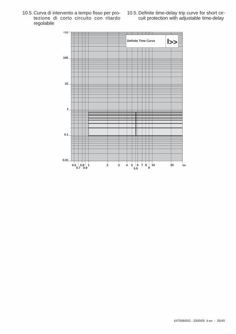
10.5. Curva di intervento a tempo fisso per pro-tezione di corto circuito con ritardoregolabile
10.5. Definite time-delay trip curve for short cir-cuit protection with adjustable time-delay
100
10
1
0.1
0.01
0.60.7
0.80.9
1 102 203 4 55.5
6 I/In
t [s]
Definite Time Curve
7 89
I>>

36/40 - 647008/002 - 2000/05 it-en
10.6. Curva di intervento a tempo fisso per prote-zione di guasto a terra attraverso toroideinterno
10.6.Definite time-delay curve for earth faultprotection by means of internal toroidaltransformer

647008/002 - 2000/05 it-en - 37/40
10.7. Curva di intervento a tempo fisso per prote-zione di guasto a terra attraverso toroideesterno
10.7. Definite time-delay curve for earth faultprotection by means of external toroidaltransformer

38/40 - 647008/002 - 2000/05 it-en
Fig. 3
11. Schema di collegamento
Per informazioni più dettagliate relative allo schema di collega-mento del PR521 montato su interruttori HAD fare riferimentoal documento “Schema circuitale n° 401701”.
11. Wiring diagram
For more detailed information about the wiring diagram of thePR521 mounted on HAD circuit-breakers, please refer to thedocument: “Circuit diagram n° 401701”.
Q
K51
>>>
>>
>
>
XK1
42
TI
L3
TIL2
9190
L1TI
43
A1
9998
9392
XK2
XK2
XK2
PR521
41
K51 YO3
A4
A4
XV
A1
XV
TIL3
9392
90
9998L1
TI
XK1
>>>
>>
>
>
K51
Q
PR5219796 PR521
X3
XK3
303
304
23
20 21 22
XK2
X3 X3 X3X3
304
303
XK3
X3
96 97
89 89
S03
20 21 2219
1 2 4
K51
5
23
P1 P1S1S2
S1S2
P2 P2
12345678
3 4 18
Y03
12345678
P1 P1S1S2
P1
S1S2
S1S2
P2 P2P2
1843
Y03
G)*
A1
A1
44
OTI
45
A4
PR521
Q
K51
>>>
>>
>
>
>
XK1
TIL3
TIL2
9190
L1TI
9998
9392
XV
Q
K51XK1
TIL1 98
99
90
9293
L3TI
>
>
>
>>
>>>
XK3
303
304
X3
PR52196 97
TIO
24 25 24 25
X3 X3 X3X3
9796
X3
304
303
XK3
89 88
* G)
P1 P1S1S2
P2
S1S2
P2
12345678
24 25 26
S1S2
12
3 4 18
Y03
P1 P1S1S2
P2
S1S2
P2
12345678
P1
P2
S1S2
24 25 26
S1S2
12
3 4 18
Y03

647008/002 - 2000/05 it-en - 39/40
Fig. 4
XK1Descrizione
XK2Descrizione
XK3Descrizione
Description Description Description
1Fase L1-1
1Comando di apertura a distanza SO3 (a)
1Sganciatore a smagnetizzazione (+)
Phase L1 Remote opening control SO3 (a) Demagnetisation release (+)
2Fase L1-2
2Comando di apertura a distanza SO3 (b)
2Sganciatore a smagnetizzazione (-)
Phase L1-2 Remote opening control SO3 (b) Demagnetisation release (-)
3Fase L2-1
3Non utilizzato
Phase L2-1 Not used
4Fase L2-2
4Contatto bistabile K51/Y03 (a)
Phase L2-2 Bistable K51/Y03 contact (a)
5Fase L3-1
5Contatto bistabile K51/Y03 (b)
Phase L3-1 Bistable K51/Y03 contact (b)
6Fase L3-2
6Non utilizzato
Phase L3-2 Not used
7Tor Ext-1Ext. Tor.-1
8Tor Ext-2Ext. Tor.-2
12. PR521 unit connections12. Connessioni dell'unità PR521

40/40 - 647008/002 - 2000/05 it-en


Per maggiori informazioni contattare: For more information please contact:
ABB S.p.A. Power Products DivisionUnità Operativa Sace-MVVia Friuli, 4I-24044 DalmineTel.: +39 035 6952 111Fax: +39 035 6952 874E-mail: [email protected]
ABB AG Calor Emag Medium Voltage Products Oberhausener Strasse 33 Petzower Strasse 8 D-40472 Ratingen D-14542 Glindow Phone: +49(0)2102/12-1230, Fax: +49(0)2102/12-1916 E-mail: [email protected]
www.abb.com
Dati e immagini non sono impegnativi. In funzione dello sviluppo tecnico e dei prodotti, ci riserviamo il diritto di modificare il contenuto di questo documento senza alcuna notifica.
The data and illustrations are not binding. We reserve the right to make changes without notice in the course of technical development of the product.
Copyright 2009 ABB. All rights reserved.
ITN
IE6
47
00
8/0
02
- it
-en
- 2
00
0.0
5 -
Rev
. B
- 2
00
9.0
9