medium voltage products pr512 manuale operativo per unità ... · medium voltage products pr512...
TRANSCRIPT

Medium Voltage Products
PR512Manuale operativo per unità di protezione a microprocessoreOperator manual for microprocessor based protection unit
Indice 1. Unità PR512/P (50-51) 4 2. Trasformatori amperometrici di fase 5 3. Funzioni di protezione 6 4. Connessioni unità 13 5. Curve tempo-corrente 18 6. Alimentazione ausiliaria 22 7. Contatti di segnalazione 22 8. Comando di apertura a distanza 22 9. Esecuzioni e fissaggio 22 10. Condizioni ambientali 23 11. Compatibilità elettromagnetica 23 12. Dati tecnici 23 13. Note e raccomandazioni 24 14. Unità PR512/P (50-51/50N-51N) 24 15. Trasform. amperometrico differenziale esterno 26 16. Funzioni di protezione 26 17. Connessioni unità 32 18. Altre informazioni 33 19. Unità PR512/PD (50-51/50N-51N dialogo) 34 20. Ingressi binari 36 21. Uscite comandi YO e YC 36 22. Funzione di dialogo 36 23. Esempio di impostazione comunicazione seriale 38 24. Connessioni unità 38 25. Dati tecnici 39 26. Note e raccomandazioni 39 27. Messa in servizio 39 28. Controlli periodici 40
15. External residual current transformer 26 16. Protection functions 26 17. Unit connections 32 18. Other information 33 19. PR512/PD (50-51/50N-51N dialogue) unit 34 20. Binary inputs 36 21. YO and YC command outputs 36 22. Dialogue function 36 23. Example of serial communication setting 38 24. Unit connections 38 25. Technical data 39 26. Notes and recommendations 39 27. Putting into service 39 28. Periodic checks 40
Index 1. PR512/P (50-51) unit 4 2. Phase current transformers 5 3. Protection functions 6 4. Unit connections 13 5. Time-current curves 18 6. Auxiliary power supply 22 7. Signalling contacts 22 8. Remote opening control 22 9. Versions and fixing 22 10. Ambient conditions 23 11. Electromagnetic compatibility 23 12. Technical data 23 13. Notes and recommendations 24 14. PR512/P (50-51/50N-51N) unit 24


1
Per la vostra sicurezza!
• Verificare che il locale di installazione (spazi, segregazionie ambiente) sia idoneo per l’apparecchiatura elettrica edelettronica.
• Verificare che tutte le operazioni di installazione, messa inservizio e manutenzione siano effettuate da personale conuna qualifica sufficiente e una conoscenza adeguata dellaapparecchiatura.
• Verificare che durante le fasi di installazione, esercizio emanutenzione vengano rispettate le prescrizioni Normativee di Legge, per l’esecuzione degli impianti secondo leregole della buona tecnica e di sicurezza sul lavoro.
• Osservare scrupolosamente le informazioni riportate nelpresente manuale d’uso.
• Verificare che durante il servizio non vengano superate leprestazioni nominali dell’apparecchiatura.
• Prestare particolare attenzione alle note indicate nel ma-nuale dal seguente simbolo:
• Assicurarsi che il personale operante sull’apparecchiatu-ra abbia a disposizione il presente manuale d’uso e leinformazioni necessarie ad un corretto intervento.
• Utilizzare solo parti di ricambio originali.
Scollegare l’unità PR512 prima di effettuare prove diisolamento sull’impianto.
!
For your safety!
• Check that the installation room (spaces, segregationsand ambient) are suitable for the electrical and electronicapparatus.
• Make sure that all the installation, putting into service andmaintenance operations are carried out by suitably quali-fied personnel with adequate knowledge of the apparatus.
• Make sure that the Standard and Legal requirements arefollowed during installation, service and maintenance, inorder to construct installations according to good techni-cal and safety working practices.
• Strictly follow all the information given in this instructionmanual.
• Check that the rated performance of the apparatus is notexceeded during service.
• Pay particular attention to the notes indicated in themanual by the following symbol:
• Check that the personnel operating the apparatus havethis instruction manual to hand, as well as the necessaryinformation for correct intervention.
• Only use original spare parts.
Disconnect the PR512 unit before carrying out anyinsulation tests on the installation.
Un comportamento responsabile salvaguar-da la vostra e l’altrui sicurezza!
Per qualsiasi esigenza contattare il ServizioAssistenza ABB.
! !
!
Responsible behaviour safeguards your ownand others’ safety!
For any requests, please contact ABB As-sistance Service.

2
Premessa
Per quanto concerne le caratteristiche elettriche e costruttive,le dimensioni di ingombro dell'unità a microprocessore PR512,vedere il catalogo tecnico ITSCB 649092.I PR512 sono normalmente impiegati come unità di protezio-ne da quadro.I modelli disponibili sono:– PR512/P (50-51): provvede alle funzioni di protezione con-
tro sovraccarico (51) e contro corto circuito istantaneo eritardato (50). Visualizza la corrente della fase più caricata.
– PR512/P (50-51-50N-51N): provvede alle funzioni di prote-zione di sovraccarico (51), contro corto circuito istantaneoe ritardato (50), contro guasto a terra prima soglia (51N) eseconda soglia (50N). Visualizza la corrente della fase piùcaricata.
– PR512/PD: possiede tutte le funzioni dell'unità PR512/P piùcompleta ed ha inoltre la possibilità di collegarsi e di dialo-gare con un sistema di gestione centralizzato (SD-View).
Introduction
With regard to the electrical and construction characteristicsand the overall dimensions of PR512 microprocessor units,please see technical catalogue ITSCB 649092.The PR512 units are normally used as switchboard protectionunits.The versions available are:– PR512/P (50-51): this carries out the protection functions
against overload (51) and against instantaneous anddelayed short-circuit (50). It displays the current of the phasewith the highest load.
– PR512/P (50-51-50N-51N): this carries out the protectionfunctions against overload (51), against instantaneous anddelayed short-circuit (50), and against first (51N) and second(50N) threshold earth fault. It displays the current of thephase with the highest load.
– PR512/PD: this has all the functions of the most completePR512/P unit and also has the possibility of being connectedto and communicating with a centralized management system(SD-View).

3
Indice
1. Unità PR512/P (50-51) Pag. 4
2. Trasformatori amperometrici di fase “ 5
3. Funzioni di protezione “ 6
4. Connessioni unità “ 13
5. Curve tempo-corrente “ 18
6. Alimentazione ausiliaria “ 22
7. Contatti di segnalazione “ 22
8. Comando di apertura a distanza “ 22
9. Esecuzioni e fissaggio “ 22
10. Condizioni ambientali “ 23
11. Compatibilità elettromagnetica “ 23
12. Dati tecnici “ 23
13. Note e raccomandazioni “ 24
14. Unità PR512/P (50-51/50N-51N) “ 24
15. Trasform. amperometrico differenziale esterno “ 26
16. Funzioni di protezione “ 26
17. Connessioni unità “ 32
18. Altre informazioni “ 33
19. Unità PR512/PD (50-51/50N-51N dialogo) “ 34
20. Ingressi binari “ 36
21. Uscite comandi YO e YC “ 36
22. Funzione di dialogo “ 36
23. Esempio di impostazione comunicazione seriale “ 38
24. Connessioni unità “ 38
25. Dati tecnici “ 39
26. Note e raccomandazioni “ 39
27. Messa in servizio “ 39
28. Controlli periodici “ 40
Index
1. PR512/P (50-51) unit Page 4
2. Phase current transformers “ 5
3. Protection functions “ 6
4. Unit connections “ 13
5. Time-current curves “ 18
6. Auxiliary power supply “ 22
7. Signalling contacts “ 22
8. Remote opening control “ 22
9. Versions and fixing “ 22
10. Ambient conditions “ 23
11. Electromagnetic compatibility “ 23
12. Technical data “ 23
13. Notes and recommendations “ 24
14. PR512/P (50-51/50N-51N) unit “ 24
15. External residual current transformer “ 26
16. Protection functions “ 26
17. Unit connections “ 32
18. Other information “ 33
19. PR512/PD (50-51/50N-51N dialogue) unit “ 34
20. Binary inputs “ 36
21. YO and YC command outputs “ 36
22. Dialogue function “ 36
23. Example of serial communication setting “ 38
24. Unit connections “ 38
25. Technical data “ 39
26. Notes and recommendations “ 39
27. Putting into service “ 39
28. Periodic checks “ 40

4
19
30
292018
45
12
3
27 28
21
17
16
6
7
N.B. L'immagine qui riprodotta è relativa allatarga frontale dell'unità PR512/PD.
N.B. The picture shown above regards thefront nameplate of the PR512/PD unit.
Fig. 1
1. Unità PR512/P (50-51)
Una corretta installazione è di primaria importanza.Le istruzioni del costruttore devono essere attenta-mente studiate e seguite.Tutte le operazioni di installazione, devono essereeffettuate da personale qualificato e con una cono-scenza adeguata dell'apparecchiatura.Scollegare l’unità PR512 prima di effettuare qualsi-asi prova di isolamento sull’impianto.
L'unità di protezione PR512/P realizza le seguenti funzioni:• 51 - protezione contro sovraccarico• 50 - protezione contro corto circuito ritardato o istantaneo.Le protezioni possono essere realizzate in modo bifase otrifase a seconda che si connettano due o tre trasformatoriamperometrici (TA). Viene inoltre visualizzata la corrente (invalore assoluto) circolante nella fase più caricata.Il PR512/P, pur avendo la possibilità di ricevere un'alimenta-zione ausiliaria, è di tipo autoalimentato e garantisce il correttofunzionamento delle funzioni di protezione in presenza di unacorrente maggiore o uguale al 20% del valore del TA, sualmeno una fase.Quando il PR512 è autoalimentato l'accensione del display ègarantita da una corrente primaria di 0,18 x In oppure, in casodi alimentazione ausiliaria, il display si accende anche adinterruttore aperto, mentre la lettura minima garantita di cor-rente, è al 5% di In. Sotto tale valore, in presenza di alimenta-zione ausiliaria, viene visualizzato "-LL-" (Low Load).La precisione di lettura è pari al 5% + LSD (Last SignificativeDigit) per valori di corrente da 0,5 a 1,5 x In.
1. PR512/P (50-51) unit
Correct installation is of primary importance. Themanufacturer’s instructions must be carefullystudied and followed.All the installation operations must be carried outby suitably qualified personnel with adequate know–edge of the apparatus.Disconnect the PR512 unit before carrying out anyinsulation test on the installation.
The PR512/P protection unit carries out the following functions:• 51 - protection against overload• 50 - protection against delayed or instantaneous short-circuit.The protections can be made either two-phase or three-phaseaccording to whether two or three current transformers (CTs)are connected. The current (in absolute value) circulating inthe phase with the highest load is also displayed.Even though it has the possibility of receiving an auxiliarypower supply, the PR512/P is of the self-powered type andensures correct operation of the protection functions in thepresence of a current higher than or equal to 20% of the CTvalue, on at least one phase.When the PR512 is self-powered, lighting up of the display isensured by a primary current of 0.18 x In or, in the case ofauxiliary power supply, the display lights up with the circuit-breaker open, whereas the minimum guaranteed currentreadout is 5% of In. Under this value, when there is an auxiliarypower supply, “-LL-” (Low Load) is displayed.Readout precision is 5% ± LSD (Last Significative Digit) forcurrent values from 0,5 to 1,5 x In.
Apertura dell'interruttore
L'unità PR512/P realizza l'aper-tura dell'interruttore, in cui è in-tegrato, tramite uno sganciatoredi apertura a demagnetizzazio-ne unico che agisce direttamen-te sul comando dell'apparec-chio.
Circuit-breaker opening
The PR512/P unit carries outopening of the circuit-breaker inwhich it is incorporated by meansof a demagnetization openingrelease which acts directly onthe operating mechanism of theapparatus.
!!

5
Legenda1 Dip-switch predisposizione soglia di intervento della protezione
I>2 Dip-switch predisposizione temporizzazione K della protezione
I>3 Dip-switch predisposizione tipo di curva (DT, NI, VI, EI) della
protezione I>4 Dip-switch predisposizione soglia di intervento protezione I>>5 Dip-switch predisposizione tempo di intervento t>> protezione
I>>6 Bandierina magnetica bistabile di segnalazione protezione I> o
I>> intervenuta7 Led di segnalazione temporizzazione in corso protezioni I> o
I>>16 Relazione tempo-corrente secondo IEC 255-417 Display visualizzante la corrente della fase più caricata18 Bandierina magnetica bistabile segnalazione di avvenuta aper-
tura a distanza dell'interruttore19 Pulsante di RESET del microprocessore e dei relè bistabili di
segnalazione SRE e µP FAULT20 Pulsante di reset delle bandierine magnetiche bistabili (rif. 6, 18)21 Led di segnalazione microprocessore guasto (µP FAULT)27 Dip-switch predisposizione calibro trasformatori amperometrici28 Tappo copri dip-switch e targhetta “In” calibro TA29 Nr. di matricola unità30 Connettore per TEST
Caption1 Dip-switch for setting the tripping threshold of protection I>2 Dip-switch for setting the time-delay K of protection I>3 Dip-switch for setting the type of curve (DT, NI, VI, EI) of
protection I>4 Dip-switch for setting the trip threshold of protection I>>5 Dip-switch for setting the trip time t>> of protection I>>6 Bistable magnetic flag indicating protection I> or I>> tripped7 LED indicating time-delay elapsing protection I> or I>>
16 Time-current relation in conformity with IEC 255-417 Display showing the phase current with the highest load18 Bistable magnetic flag indicating remote opening of circuit-
breaker19 RESET pushbutton for microprocessor and bistable relays
signalling SRE and µP FAULT20 Reset pushbutton for bistable magnetic flags (refs. 6, 18)21 LED indicating microprocessor fault (µP FAULT)27 Dip-switch for setting rated current of current transformers28 Dip-switch and CT “In” setting plate cover29 Unit serial number30 TEST connector
2. Trasformatori amperometrici di fase
Tutte le operazioni di programmazione, devono es-sere effettuate da personale con una qualifica suffi-ciente e una conoscenza adeguata dell’apparec-chiatura.Scollegare l’unità PR512 prima di effettuare qualsi-asi prova di isolamento sull’impianto.Nel caso in cui la corrente nominale dell’interruttoresia minore della corrente nominale del trasformato-re amperometrico (esempio: interruttore HD4 da630 A con TA da 1250 A) è obbligatorio predisporrela funzione 51 e 51N (I> e Io>) in modo tale da NONSUPERARE la portata amperometrica nominale del-l’interruttore controllato (nel ns. esempio il valoremassimo è I> = 0,5 e Io> = 0,5).
I trasformatori amperometrici di fase connessi all'unità svolgo-no due funzioni:a) fornire l'energia necessaria al corretto funzionamento;b) fornire il segnale necessario al rilevamento della corrente.Il PR512/P può essere impiegato con otto diversi TA, caratte-rizzati dai seguenti valori:– Corrente nominale secondaria 1 A– Prestazione 2,5 VA– Precisione 5 P 10– Fattore di sicurezza 15– Prestazione termica Ith = 25 kA x 1s a 50 Hz– Frequenza di lavoro 50-60 Hz– Per la corretta lettura dell'amperometro è necessario abbina-
re TA con le seguenti correnti nominali primarie:40 A, 80 A, 100 A, 150 A, 200 A, 250 A, 600 A, 1250 A.
Sul fronte dell'unità è possibile selezionare i dip-switch, relativiai TA montati (fig. 1 - rif. 27), nel seguente modo:
2. Phase current transformers
All the programming operations must be carried outby suitably qualified personnel with adequateknowledge of the apparatus.Disconnect the PR512 unit before carrying out anyinsulation test on the installation.When the rated current of the circuit-breaker is lowerthan the rated current of the current transformer(e.g.: HD4 630 A circuit-breaker with 1250 A CT), it iscompulsory to provide function 51 and 51N (I> andIo>) so that the rated current capacity of the circuit-breaker controlled is NOT EXCEEDED (in ourexample, the maximum value is I> = 0.5 and Io> = 0.5).
The phase current transformers connected to the unit carry outthe following two functions:a) they supply the energy required for correct operation;b) they supply the signal required to sense the current.The PR512/P can be used with eight different CTs, character-ized by the following values:– Rated secondary current 1 A– Performance 2.5 VA– Precision 5 P 10– Safety factor 5– Thermal performance Ith = 25 kA x 1s a 50 Hz– Operating frequency 50-60 Hz– For correct ammeter readout, the CT must be combined with
the following rated primary currents:40 A, 80 A, 100 A, 150 A, 200 A, 250 A, 600 A, 1250 A.
The dip-switches - relative to the CTs mounted (fig. 1 - ref. 27)- can be selected on the front of the unit as follows:
TA40A
TA80A
TA150A
TA200A
TA250A
TA1250A
TA600A
TA100A
!!

6
Dove:I = corrente di sovraccaricoI> = corrente di soglia regolatat = tempo di interventoα − β = costanti che definiscono il tipo di caratteristicaK = fattore di moltiplicazione del tempo di intervento
3.1.1. Scelta del valore di soglia (I>)
L'impostazione di I> viene effettuata agendo sui 6 dip switchindicati in fig. 1 - rif. 1.La somma dei valori selezionati rappresenta la frazione di Incorrispondente a I>.Sono disponibili 32 valori di soglia, così definiti: 0,2 ... 1 x In conpasso 0,025 x In (non è possibile la predisposizione a 0,6 x In).La protezione può essere esclusa posizionando il primo dipswitch sulla posizione OFF.Nella seguente tabella si evidenziano le possibil ipredisposizioni.
Where:I = overload currentI> = set threshold currentt = trip timeα − β = constants which define the type of characteristicK = multiplication factor of the trip time
3.1.1. Selection of the threshold value (I>)
Setting the I> is carried out by acting on the 6 dip-switchesshown in fig. 1 - ref. 1.The sum of the values selected represents the fraction of Incorresponding to I>.32 threshold values are available, defined as follows: 0.2 ... 1x In with steps of 0.025 x In (presetting to 0.6 x In is not possible).The protection can be excluded by positioning the first dip-switch on OFF.The table below shows the possible settings.
3. Funzioni di protezione
Il PR512/P (50-51) realizza due funzioni di protezione (indi-pendenti ed escludibili) contro sovraccarico e cortocircuito.
3.1. Protezione contro sovraccarico (51)
La funzione di protezione elabora il vero valore efficace (RMS)per valori di corrente tra 0,2 e 2 x In. Per valori superiori laprotezione lavora sul valore di picco.Sono disponibili 4 diverse famiglie di curve di protezione:– Tempo indipendente regolabile (DT = Definite Time/tempo
indipendente)– Tempo inverso (NI = Normally Inverse/tempo inverso)– Tempo molto inverso (VI = Very Inverse/tempo molto inverso)– Tempo estremamente inverso (EI = Extremely Inverse/tem-
po estremamente inverso).Il valore di soglia di questa protezione viene indicato con I>,mentre il relativo tempo d'intervento viene indicato con t>.L'inizio della temporizzazione è segnalata dall'accensionedel led ALARM (fig. 1 - rif. 7) mentre l'avvenuta aperturadell'interruttore è segnalata frontalmente dalla bandierinamagnetica I> I>> (fig. 1 - rif. 6) ruotata nella posizione di colorgiallo.Per ripristinare questa segnalazione è necessario premere ilpulsante FLAG RESET (fig. 1 - rif. 20) sul fronte dell'unitàgarantendo una delle seguenti condizioni:a) tensione ausiliaria 24 V cc presente (display acceso);b) corrente circolante primaria maggiore di 0,2 x In (display
acceso con indicazione della corrente circolante);c) applicazione del dispositivo TT2 al connettore TEST (fig.
1 - rif. 30) posto sul fronte dell'unità (accessorio a richiesta).Per le protezioni a tempo indipendente, il tempo di interventodelL'unità è dato dalla relazione:
t = K x β
Per le protezioni a tempo inverso, in accordo con le Norme IEC255-4, il tempo d'intervento è dato dalla relazione:
βt> = K x
[I/I>]a - 1
3. Protection functions
The PR512/P (50-51) carries out two protection functions(which are independent and can be excluded) against over-load and short-circuit.
3.1. Protection against overload (51)
The protection function calculates the true effective value(RMS) for current values between 0.2 and 2 x In. For highervalues, the protection works on the peak value.There are 4 different families of protection curves available:– Definite adjustable time (DT = Definite Time)– Inverse time (NI = Normally Inverse time)– Very inverse time (VI = Very Inverse time)– Extremely inverse time (EI = Extremely Inverse time)The threshold value of this protection is indicated by 1>,whereas the relative trip time is indicated by t>.The start of timing is signalled by the ALARM LED lighting up(fig. 1 - ref. 7), whereas circuit-breaker opening is signalled onthe front by the magnetic flag I> I>> (fig. 1 - ref. 6) in the yellowposition.To reset this signal, the FLAG RESET button must be pressed(fig. 1 - ref. 20) on the front of the unit, thereby guaranteeing oneof the following conditions:a) 24 V d.c. auxiliary voltage present (display lit);b) primary circulating current higher than 0.2 x In (display lit
with indication of the current circulating);c) application of the TT2 device to the TEST connector (fig. 1
- ref. 30) on the front of the unit (optional accessory).For the definite time protections, the trip time of the unit is givenby the following relation:
t = K x β
For inverse time protections, in compliance with IEC 255-4Standards, the trip time is given by the relation:
βt> = K x
[I/I>]a - 1

7
OFF
0,200xIn
0,225xIn
0,250xIn
0,275xIn
0,300xIn
0,325xIn
0,350xIn
0,375xIn
0,400xIn
0,425xIn
0,450xIn
0,475xIn
0,500xIn
0,525xIn
0,550xIn
0,575xIn
0,625xIn
0,650xIn
0,675xIn
0,700xIn
0,725xIn
0,750xIn
0,775xIn
0,800xIn
0,825xIn
0,850xIn
0,875xIn
0,900xIn
0,925xIn
0,950xIn
0,975xIn
1,000xIn
Fig. 2
3.1.2. Selection of the type of curve
Four different time-current relations can be selected by meansof the dip-switches indicated in fig. 1 ref. 3. The sum of theselected values indicates the type of curve selected.N.B. To define the K parameter, see paragraph 3.1.3.
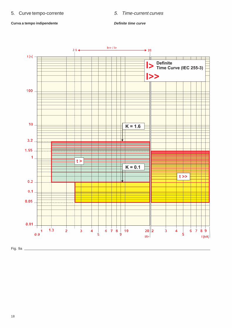
Definite time curve (DT): (ß=2) (see fig. 9 a)
Set the dip-switches as follows:
Mathematical relation to find t>: t> = K x 2
Inverse time curve (NI): a=0.02; ß>=0.14 (see fig. 9 b)
Set the dip-switches as follows:
0.14Mathematical relation to find t>: t> = K x
[I/I>]0,02 - 1
where I represents the overload current and I> the set thresh-old current.
3.1.2. Scelta del tipo di curva
Possono essere selezionate quattro diverse relazioni tempo-corrente, mediante i dip switch indicati in fig. 1 rif. 3.La somma dei valori selezionati indica il tipo di curva prescelto.N.B. Per la definizione del parametro K vedere paragrafo3.1.3.
Curva a tempo indipendente (DT): (ß=2) (vedi fig. 9 a)
Predisporre i dip-switch in questo modo:
Relazione matematica per trovare t>: t> = K x 2
Curva a tempo inverso (NI): a=0,02; ß=0,14 (vedi fig. 9 b)
Predisporre i dip-switch in questo modo:
0,14Relazione matematica per trovare t>: t> = K x
[I/I>]0,02 - 1
dove I rappresenta la corrente di sovraccarico e I> la correntedi soglia regolata.

8
3.1.3. Scelta del tempo di intervento (t>)
Il tempo di intervento della protezione viene regolato agendosui dip-switch di fig. 1 - rif. 2. Tramite questi selettori vieneimpostato il valore di K che sostituito nelle relazioni precedentidetermina il tempo d'intervento. Sono disponibili 16 valori diK così definiti: da 0,1 a 1,6 con passo 0,1.Nella seguente tabella si evidenziano le possibil ipredisposizioni:
K0,1
K0,2
K0,3
K0,4
K0,5
K0,6
K0,7
K0,8
K0,9
K1,0
K1,1
K1,2
K1,3
K1,4
K1,5
K1,6
Fig. 3
Very inverse time curve (VI): a=1; ß>=13.5 (see fig. 9 c)
Set the dip-switches as follows:
13.5Mathematical relation to find t>: t> = K x
[I/I>]1 - 1
where I represents the overload current and I> the set thresh-old current.
Extremely inverse time curve (EI): a=2; ß>=80 (see fig. 9 d)
Set the dip-switches as follows:
80Mathematical relation to find t>: t> = K x
[I/I>]2 - 1
where I represents the overload current and I> the set thresh-old current.
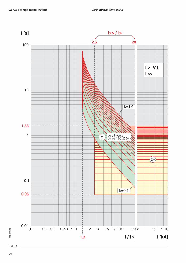
Curva a tempo molto inverso (VI): a=1; ß=13,5 (vedi fig. 9 c)
Predisporre i dip-switch in questo modo:
13,5Relazione matematica per trovare t>: t> = K x
[I/I>]1 - 1
dove I rappresenta la corrente di sovraccarico e I> la correntedi soglia regolata.
Curva a tempo estremam. inverso (EI): a=2; ß=80 (vedi fig. 9 d)
Predisporre i dip-switch in questo modo:
80Relazione matematica per trovare t>: t> = K x
[I/I>]2 - 1
dove I rappresenta la corrente di sovraccarico e I> la correntedi soglia regolata.
3.1.3. Selection of the trip time (t>)
The protection trip time is set by using the dip-switches in fig.1 - ref. 2. By means of these selectors, the value of K is set which,replaced in the previous relations, determines the trip time.There are 16 K values available defined as follows: from 0.1to 1.6 with steps of 0.1.The table below shows the possible settings:
9
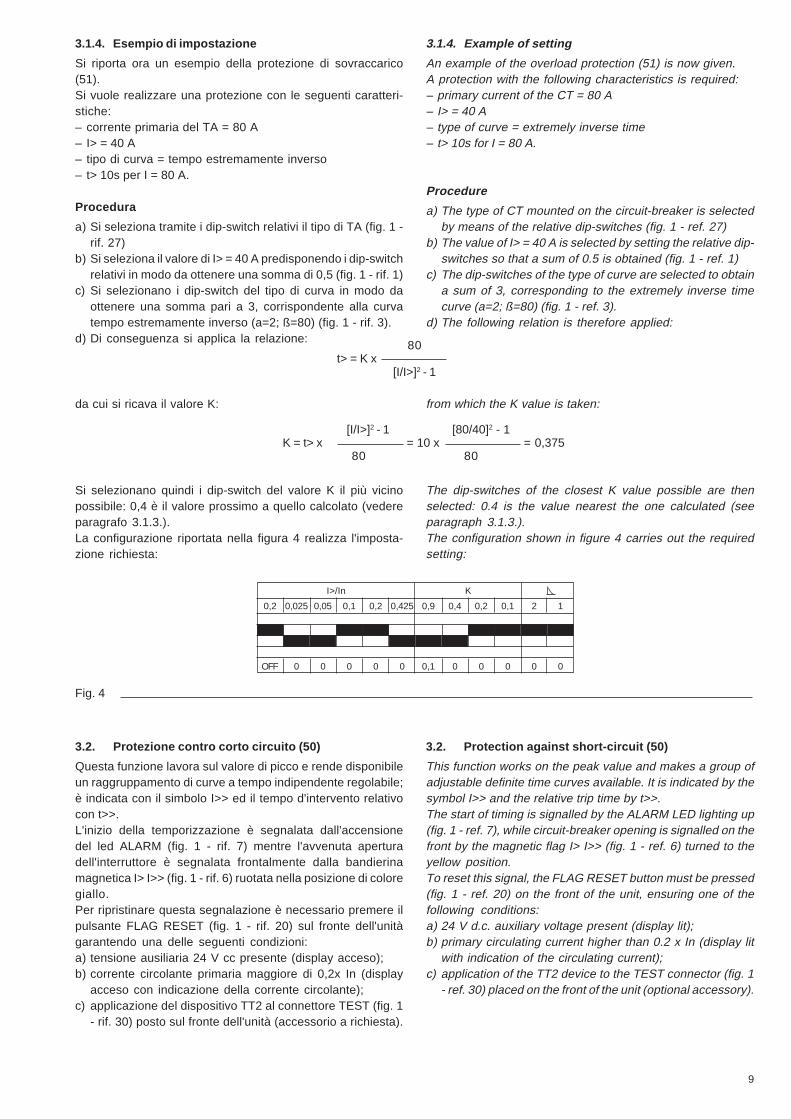
3.1.4. Esempio di impostazione
Si riporta ora un esempio della protezione di sovraccarico(51).Si vuole realizzare una protezione con le seguenti caratteri-stiche:– corrente primaria del TA = 80 A– I> = 40 A– tipo di curva = tempo estremamente inverso– t> 10s per I = 80 A.
Procedura
a) Si seleziona tramite i dip-switch relativi il tipo di TA (fig. 1 -rif. 27)
b) Si seleziona il valore di I> = 40 A predisponendo i dip-switchrelativi in modo da ottenere una somma di 0,5 (fig. 1 - rif. 1)
c) Si selezionano i dip-switch del tipo di curva in modo daottenere una somma pari a 3, corrispondente alla curvatempo estremamente inverso (a=2; ß=80) (fig. 1 - rif. 3).
d) Di conseguenza si applica la relazione: 80t> = K x
[I/I>]2 - 1
da cui si ricava il valore K:
[I/I>]2 - 1 [80/40]2 - 1K = t> x = 10 x = 0,375
80 80
Si selezionano quindi i dip-switch del valore K il più vicinopossibile: 0,4 è il valore prossimo a quello calcolato (vedereparagrafo 3.1.3.).La configurazione riportata nella figura 4 realizza l'imposta-zione richiesta:
I>/In K
OFF 0 0 0 0 0 0,1 0 0 0 0 0
0,2 0,025 0,05 0,1 0,2 0,425 0,9 0,4 0,2 0,1 2 1
Fig. 4
3.2. Protezione contro corto circuito (50)
Questa funzione lavora sul valore di picco e rende disponibileun raggruppamento di curve a tempo indipendente regolabile;è indicata con il simbolo I>> ed il tempo d'intervento relativocon t>>.L'inizio della temporizzazione è segnalata dall'accensionedel led ALARM (fig. 1 - rif. 7) mentre l'avvenuta aperturadell'interruttore è segnalata frontalmente dalla bandierinamagnetica I> I>> (fig. 1 - rif. 6) ruotata nella posizione di coloregiallo.Per ripristinare questa segnalazione è necessario premere ilpulsante FLAG RESET (fig. 1 - rif. 20) sul fronte dell'unitàgarantendo una delle seguenti condizioni:a) tensione ausiliaria 24 V cc presente (display acceso);b) corrente circolante primaria maggiore di 0,2x In (display
acceso con indicazione della corrente circolante);c) applicazione del dispositivo TT2 al connettore TEST (fig. 1
- rif. 30) posto sul fronte dell'unità (accessorio a richiesta).
3.1.4. Example of setting
An example of the overload protection (51) is now given.A protection with the following characteristics is required:– primary current of the CT = 80 A– I> = 40 A– type of curve = extremely inverse time– t> 10s for I = 80 A.
Procedure
a) The type of CT mounted on the circuit-breaker is selectedby means of the relative dip-switches (fig. 1 - ref. 27)
b) The value of I> = 40 A is selected by setting the relative dip-switches so that a sum of 0.5 is obtained (fig. 1 - ref. 1)
c) The dip-switches of the type of curve are selected to obtaina sum of 3, corresponding to the extremely inverse timecurve (a=2; ß=80) (fig. 1 - ref. 3).
d) The following relation is therefore applied:
from which the K value is taken:
The dip-switches of the closest K value possible are thenselected: 0.4 is the value nearest the one calculated (seeparagraph 3.1.3.).The configuration shown in figure 4 carries out the requiredsetting:
3.2. Protection against short-circuit (50)
This function works on the peak value and makes a group ofadjustable definite time curves available. It is indicated by thesymbol I>> and the relative trip time by t>>.The start of timing is signalled by the ALARM LED lighting up(fig. 1 - ref. 7), while circuit-breaker opening is signalled on thefront by the magnetic flag I> I>> (fig. 1 - ref. 6) turned to theyellow position.To reset this signal, the FLAG RESET button must be pressed(fig. 1 - ref. 20) on the front of the unit, ensuring one of thefollowing conditions:a) 24 V d.c. auxiliary voltage present (display lit);b) primary circulating current higher than 0.2 x In (display lit
with indication of the circulating current);c) application of the TT2 device to the TEST connector (fig. 1
- ref. 30) placed on the front of the unit (optional accessory).

10
3.2.1. Scelta del valore di soglia (I>>)
L'impostazione della soglia I>> viene effettuata agendo sui 5dip-switch indicati in fig. 1 - rif. 4.La somma dei valori selezionati rappresenta il multiplo di I>corrispondente a I>>.N.B. Anche se la protezione I> è in OFF, la predisposizione ècomunque valida per la funzione I>>; in particolare il primo dip-switch della protezione I> è sempre considerato come valoreuguale a 0,2.Sono disponibili 16 valori di soglia e le predisposizioni sonoqui sotto riportate.
OFF
2,5xI>
3,5xI>
4,5xI>
5,5xI>
7,5xI>
8,5xI>
9,5xI>
10,5xI>
12xI>
13xI>
14xI>
15xI>
17xI>
18xI>
19xI>
20xI>
Fig. 5
3.2.1. Selection of the threshold value (I>>)
Setting the I>> threshold value is carried out by using the 5 dip-switches shown in fig. 1 - ref. 4.The sum of the values selected represents the multiple of I>corresponding to I>>.N.B. Even if the I> protection is on OFF, the setting is still validfor the I>> function. In particular, the first dip-switch of the I>protection is always considered as having a value of 0.2.16 threshold values are available and the settings are shownbelow.
11
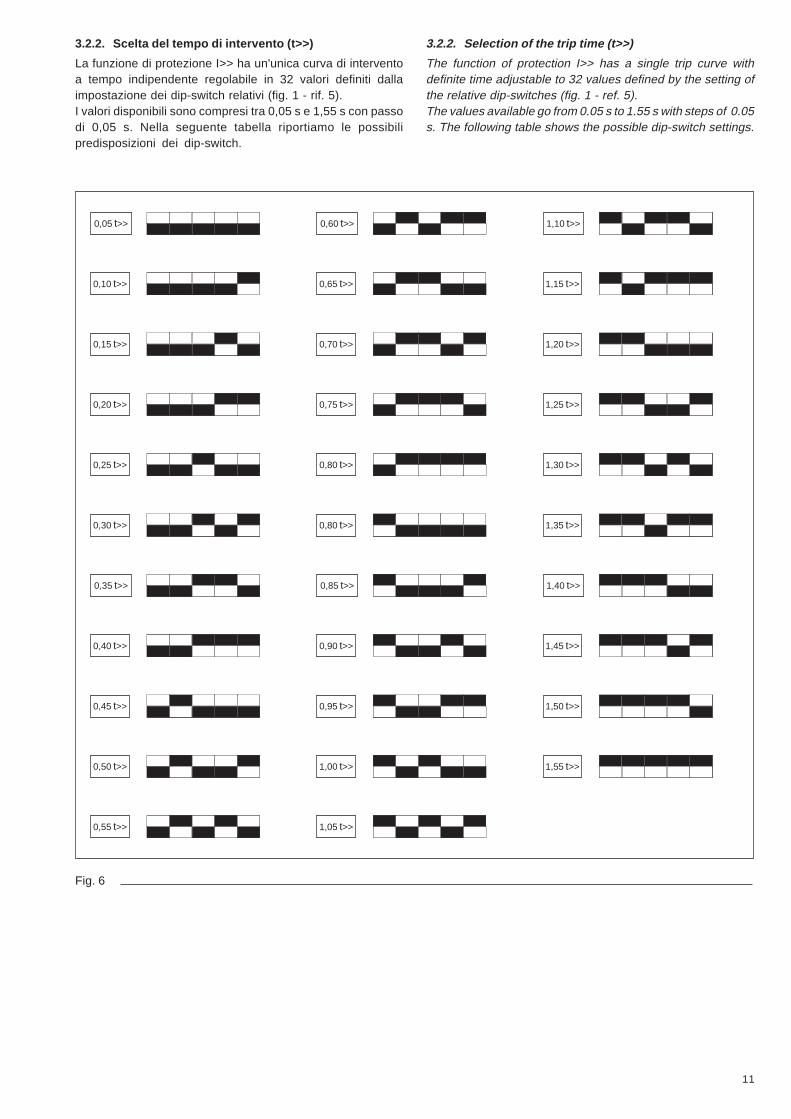
3.2.2. Scelta del tempo di intervento (t>>)
La funzione di protezione I>> ha un'unica curva di interventoa tempo indipendente regolabile in 32 valori definiti dallaimpostazione dei dip-switch relativi (fig. 1 - rif. 5).I valori disponibili sono compresi tra 0,05 s e 1,55 s con passodi 0,05 s. Nella seguente tabella riportiamo le possibilipredisposizioni dei dip-switch.
0,05 t>>
0,10 t>>
0,15 t>>
0,20 t>>
0,25 t>>
0,30 t>>
0,35 t>>
0,40 t>>
0,45 t>>
0,50 t>>
0,55 t>>
0,60 t>>
0,65 t>>
0,70 t>>
0,75 t>>
0,80 t>>
0,80 t>>
0,85 t>>
0,90 t>>
0,95 t>>
1,00 t>>
1,05 t>>
1,10 t>>
1,15 t>>
1,20 t>>
1,25 t>>
1,30 t>>
1,35 t>>
1,40 t>>
1,45 t>>
1,50 t>>
1,55 t>>
Fig. 6
3.2.2. Selection of the trip time (t>>)
The function of protection I>> has a single trip curve withdefinite time adjustable to 32 values defined by the setting ofthe relative dip-switches (fig. 1 - ref. 5).The values available go from 0.05 s to 1.55 s with steps of 0.05s. The following table shows the possible dip-switch settings.

12
3.2.3. Esempio di impostazione
Si riporta ora un esempio di impostazione della protezione dicorto circuito I>> (50). Si vuole realizzare una protezione conle seguenti caratteristiche:– corrente primaria del TA = 80 A– I> = 40 A– I>> = 420 A– t>> = 0,2 s
Procedura
a) Si seleziona tramite i dip-switch relativi il tipo di TA montatosull'interruttore (fig. 1 - rif. 27)
b) Si seleziona il valore di I> = 40 A predisponendo i dip-switchrelativi in modo da ottenere una somma di 0,5 (fig. 1 - rif. 1)
c) Si calcola il rapporto I>> /I>, cioè, 420 A / 40 A = 10,5.Si selezionano i dip-switch relativi alla funzione I>> in modotale che la somma sia 10,5 (fig. 1 - rif. 4).
d) Si seleziona il tempo desiderato t>> = 0,2 s agendo sui dip-switch relativi (fig. 1 - rif. 5).
La configurazione riportata nella figura 7 realizza l'imposta-zione richiesta.
I>>I>
t>>
OFF 0 0 0 0 0,05 0 0 0 0
2,5 1 2 5 9,5 0,8 0,4 0,2 0,1 0,05
Fig. 7
3.2.3. Example of setting
An example of setting the short-circuit protection I>> (50) isnow given. A protection with the following characteristics isrequired:– primary current of the CT = 80 A– I> = 40 A– I>> = 420 A– t>> = 0.2 s
Procedure
a) The type of CT mounted on the circuit-breaker is selectedby means of the relative dip-switches (fig. 1 - ref. 27)
b) The value of I> = 40 A is selected by setting the relative dip-switches so that a sum of 0.5 is obtained (fig. 1 - ref. 1)
c) The I>> /I> relation is calculated, i.e. 420 A / 40 A = 10.5.The dip-switches relative to the I>> function are selected sothat the sum is 10.5 (fig. 1 - ref. 4).
d) The t>> = 0.02 s time required is selected using the relativedip-switches (fig. 1 - ref. 5).
The configuration shown in figure 7 carries out the requiredsetting.
Non usatiNot used

13
Fig. 8
1234
5678
XK1
1
2
1
2
3
4
XK3
XK2 1234678910
XK5
4. Connessioni unità
Legenda delle connessioni unità in riferimento alla fig. 8 conrelative descrizioni:
XK1 XK31 Inizio fase L1 1 Solenoide d'apertura (+)2 Fine fase L1 2 Solenoide d'apertura (-)3 Inizio fase L24 Fine fase L2 XK55 Inizio fase L3 1 Non utilizzato6 Fine fase L3 2 Comando di apertura a distanza(a)7 Non utilizzato 3 Non utilizzato8 Non utilizzato 4 Non utilizzato
5 Non utilizzatoXK2 6 Contatto bistabile SRE (a)1 Ingresso Vaux (+) 7 Contatto bistabile SRE (b)2 Ingresso Vaux (-) 8 Contatto bistabile µP (a)3 Non utilizzato 9 Contatto bistabile µP (b)4 Non utilizzato 10 Comando di apertura a distanza(b)
4. Unit connections
Caption to the unit connections with reference to fig. 8 andrelative descriptions:
XK1 XK31 Start of L1 phase 1 Opening solenoid (+)2 End of L1 phase 2 Opening solenoid (-)3 Start of L2 phase4 End of L2 phase XK55 Start of L3 phase 1 Not used6 End of L3 phase 2 Remote opening control (a)7 Not used 3 Not used8 Not used 4 Not used
5 Not usedXK2 6 Bistable contact SRE (a)1 Input Vaux (+) 7 Bistable contact SRE (b)2 Input Vaux (-) 8 Bistable contact μP (a)3 Not used 9 Bistable contact μP (b)4 Not used 10 Remote opening control (b)

14
4.1. Schema elettrico circuitale
Circuiti per unità PR512/P (50-51/50-50N-51-51N)
4.1. Electric circuit diagram
Circuits for PR512/P units (50-51/50-50N-51-51N)
Stato di funzionamento rappresentato
Lo schema è rappresentato nelle seguenti condizioni:– interruttore aperto e inserito (vedi nota B)– circuiti in assenza di tensione– molle di chiusura dell’interruttore scariche– sganciatore di massima corrente non intervenuto.
Legenda
* = Vedere la nota indicata dalla letteraK51 = Sganciatore di massima corrente a microprocesso-
re tipo PR512/P (protezione) o PR512/PD (protezio-ne e dialogo), con le seguenti funzioni protettive(vedi nota C):– contro sovraccarico con tempo di intervento lungo
indipendente, inverso, molto inverso o estrema-mente inverso
– contro corto circuito con tempo di intervento breveindipendente
– contro guasto a terra con tempo di interventolungo indipendente, inverso, molto inverso o estre-mamente inverso (con l'unità PR512/P questafunzione viene fornita solo a richiesta)
– contro guasto a terra con tempo di interventobreve indipendente (con lo sganciatore PR512/Pquesta funzione viene fornita solo a richiesta)
Operational state shown
The diagram indicates the following conditions:– circuit-breaker off and connected (see note B)– circuits de-energized– circuit-breaker closing springs discharged– overcurrent release not tripped.
Caption
* = See note indicated by the letterK51 = Microprocessor-based overcurrent release type
PR512/P, (protection) or PR512/PD (protection anddialogue), with the following protective functions(see note C):– against overload with definite, inverse, very in-
verse or extremely inverse long time-delay trip– against short-circuit with definite short time-delay
trip– against earth fault with definite, inverse, very in-
verse or extremely inverse long time-delay trip(with PR512/P release this function is supplied onrequest only)
– against earth fault with definite short time-delaytrip (with PR512/P release this function is suppliedon request only)

15
Circuiti aggiuntivi per unità PR512/PD Additional circuits for PR512/PD unit
K51/YC = Comando di chiusura da sganciatore PR512/PDK51/YO = Comando di apertura da sganciatore PR512/PDK51/YO3 = Contatto per la segnalazione elettrica di
solenoide YO3 intervenuto per massima corren-te
K51/µP = Contatto per la segnalazione elettrica di anoma-lie nel funzionamento del microprocessore
Q/... = Contatti ausiliari dell’interruttoreS33M = Contatto di fine corsa del motore carica molle
dell’interruttoreS43 = Commutatore di predisposizione al comando
distanza/localeS75I = Contatto per la segnalazione elettrica di interrut-
tore in posizione di inserito, ubicato nel conteni-tore (vedi nota B)
SC = Pulsante o contatto per chiusura interruttoreSO = Pulsante o contatto per apertura dell’interruttoreSO3 = Contatto per l’apertura dell’interruttore tramite il
solenoide YO3TI/L1...L3 = Trasform. di corrente sulle fasi L1-L2-L3 (nota C)TI/O = Trasformatore di corrente toroidale per la misura
della corrente di guasto a terra (vedi nota F)Uaux. = Tensione di alimentaz. ausiliaria (vedi nota D)W1 = Interfaccia seriale con il sistema di controllo (in-
terfaccia EIA RS485) del relè PR512/PD (nota E)X = Connettore circuiti comando interruttore (nota B)XK1 = Morsettiera circuiti amper. sganciatore PR512XK2...XK6= Connettori circuiti ausiliari sganciatore PR512XZ = Morsettiera nel quadro (vedi nota B)YC = Sganciatore di chiusura dell’interruttoreYO1 = Sganciatore di apertura dell’interruttoreYO3 = Solenoide di apertura dell’interruttore con inter-
vento per massima corrente.
K51/YC = Closing control by PR512/PD releaseK51/YO = Opening control by PR512/PD releaseK51/YO3 = Contact signalling YO3 solenoid tripped for over-
currentK51/µP = Contact signalling microprocessor malfunctionQ\... = Circuit-breaker auxiliary contactsS33M = Limit contact of the spring-charging motor of the
circuit-breakerS43 = Remote/local selector deviceS75I = Contact signalling circuit-breaker in the connected
position, located in the enclosure (see note B)SC = Pushbutton or contact fo c. breaker closingSO = Pushbutton or contact for c. breaker openingSO3 = Contact for circuit-breaker opening through the
YO3 solenoidTI/L1...L3 = Current transformers located on L1-L2-L3 phases
(see note C)TI/O = Toroidal current transformer for measuring the
earth fault current (see note F)Uaux. = Auxiliary supply voltage (see note D)W1 = Serial interface with control system (EIA RS485
interface) of the PR512 relay (see note E)X = Circuit-breaker operating mechanism circuit con-
nector (see note B)XK1 = PR512 release current circuit terminal boardXK2...XK6= PR512 release auxiliary circuit connectorsXZ = Terminal board in switchboard (see note B)YC = Circuit-breaker shunt closing releaseYO1 = Circuit-breaker shunt opening releaseYO3 = Circuit-breaker opening solenoid with tripping
for overcurrent.
16
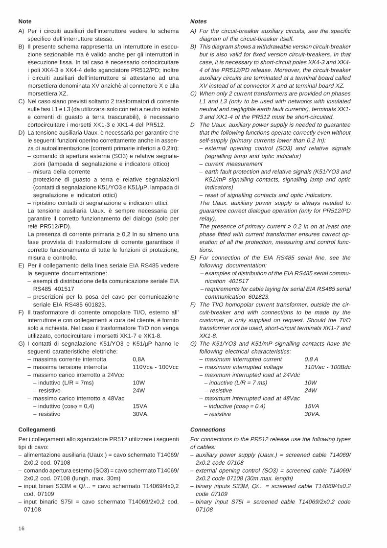
Note
A) Per i circuiti ausiliari dell’interruttore vedere lo schemaspecifico dell’interruttore stesso.
B) Il presente schema rappresenta un interruttore in esecu-zione sezionabile ma è valido anche per gli interruttori inesecuzione fissa. In tal caso è necessario cortocircuitarei poli XK4-3 e XK4-4 dello sganciatore PR512/PD; inoltrei circuiti ausiliari dell’interruttore si attestano ad unamorsettiera denominata XV anzichè al connettore X e allamorsettiera XZ.
C) Nel caso siano previsti soltanto 2 trasformatori di correntesulle fasi L1 e L3 (da utilizzarsi solo con reti a neutro isolatoe correnti di guasto a terra trascurabili), è necessariocortocircuitare i morsetti XK1-3 e XK1-4 del PR512.
D) La tensione ausiliaria Uaux. è necessaria per garantire chele seguenti funzioni operino correttamente anche in assen-za di autoalimentazione (correnti primarie inferiori a 0,2In):– comando di apertura esterna (SO3) e relative segnala-
zioni (lampada di segnalazione e indicatore ottico)– misura della corrente– protezione di guasto a terra e relative segnalazioni
(contatti di segnalazione K51/YO3 e K51/µP, lampada disegnalazione e indicatori ottici)
– ripristino contatti di segnalazione e indicatori ottici.La tensione ausiliaria Uaux. è sempre necessaria pergarantire il corretto funzionamento del dialogo (solo perrelè PR512/PD).La presenza di corrente primaria > 0,2 In su almeno unafase provvista di trasformatore di corrente garantisce ilcorretto funzionamento di tutte le funzioni di protezione,misura e controllo.
E) Per il collegamento della linea seriale EIA RS485 vederela seguente documentazione:– esempi di distribuzione della comunicazione seriale EIA
RS485 401517– prescrizioni per la posa del cavo per comunicazione
seriale EIA RS485 601823.F) Il trasformatore di corrente omopolare TI/O, esterno all’
interruttore e con collegamenti a cura del cliente, è fornitosolo a richiesta. Nel caso il trasformatore TI/O non vengautilizzato, cortocircuitare i morsetti XK1-7 e XK1-8.
G) I contatti di segnalazione K51/YO3 e K51/µP hanno leseguenti caratteristiche elettriche:– massima corrente interrotta 0,8A– massima tensione interrotta 110Vca - 100Vcc– massimo carico interrotto a 24Vcc
– induttivo (L/R = 7ms) 10W– resistivo 24W
– massimo carico interrotto a 48Vac– induttivo (cosϕ = 0,4) 15VA– resistivo 30VA.
Collegamenti
Per i collegamenti allo sganciatore PR512 utilizzare i seguentitipi di cavo:– alimentazione ausiliaria (Uaux.) = cavo schermato T14069/
2x0,2 cod. 07108– comando apertura esterno (SO3) = cavo schermato T14069/
2x0,2 cod. 07108 (lungh. max. 30m)– input binari S33M e Q/... = cavo schermato T14069/4x0,2
cod. 07109– input binario S75I = cavo schermato T14069/2x0,2 cod.
07108
Notes
A) For the circuit-breaker auxiliary circuits, see the specificdiagram of the circuit-breaker itself.
B) This diagram shows a withdrawable version circuit-breakerbut is also valid for fixed version circuit-breakers. In thatcase, it is necessary to short-circuit poles XK4-3 and XK4-4 of the PR512/PD release. Moreover, the circuit-breakerauxiliary circuits are terminated at a terminal board calledXV instead of at connector X and at terminal board XZ.
C) When only 2 current transformers are provided on phasesL1 and L3 (only to be used with networks with insulatedneutral and negligible earth fault currents), terminals XK1-3 and XK1-4 of the PR512 must be short-circuited.
D The Uaux. auxiliary power supply is needed to guaranteethat the following functions operate correctly even withoutself-supply (primary currents lower than 0.2 In):– external opening control (SO3) and relative signals
(signalling lamp and optic indicator)– current measurement– earth fault protection and relative signals (K51/YO3 and
K51/mP signalling contacts, signalling lamp and opticindicators)
– reset of signalling contacts and optic indicators.The Uaux. auxiliary power supply is always needed toguarantee correct dialogue operation (only for PR512/PDrelay).The presence of primary current > 0.2 In on at least onephase fitted with current transformer ensures correct op-eration of all the protection, measuring and control func-tions.
E) For connection of the EIA RS485 serial line, see thefollowing documentation:– examples of distribution of the EIA RS485 serial commu-
nication 401517– requirements for cable laying for serial EIA RS485 serial
communication 601823.F) The TI/O homopolar current transformer, outside the cir-
cuit-breaker and with connections to be made by thecustomer, is only supplied on request. Should the TI/Otransformer not be used, short-circuit terminals XK1-7 andXK1-8.
G) The K51/YO3 and K51/mP signalling contacts have thefollowing electrical characteristics:– maximum interrupted current 0.8 A– maximum interrupted voltage 110Vac - 100Bdc– maximum interrupted load at 24Vdc – inductive (L/R = 7 ms) 10W
– resistive 24W– maximum interrupted load at 48Vac – inductive (cosϕ = 0.4) 15VA – resistive 30VA.
Connections
For connections to the PR512 release use the following typesof cables:– auxiliary power supply (Uaux.) = screened cable T14069/
2x0.2 code 07108– external opening control (SO3) = screened cable T14069/
2x0.2 code 07108 (30m max. length)– binary inputs S33M, Q/... = screened cable T14069/4x0.2
code 07109– binary input S75I = screened cable T14069/2x0.2 code
07108
17
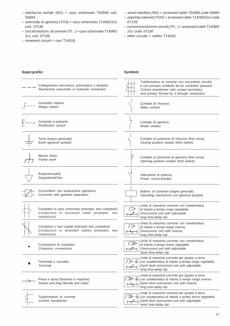
– interfaccia seriale (W1) = cavo schermato T54566 cod.56884
– solenoide di apertura (YO3) = cavo schermato T14065/2x1cod. 07136
– circuiti trasform. di corrente (TI/...) = cavo schermato T14065/2x1 cod. 07136
– rimanenti circuiti = cavi T14018.
– serial interface (W1) = screened cable T54566 code 56884– opening solenoid (YO3) = screened cable T14065/2x1 code
07136– current transformer circuits (TI/...) = screened cable T14065/
2x1 code 07136– other circuits = cables T14018.
Segni grafici Symbols
Trasformatore di corrente con secondario avvoltoe con primario costituito da tre conduttori passantiCurrent transformer with wonad secondaryand primary formed by 3 through conductors
Collegamento meccanico, pneumatico o idraulicoMechanical, pneumatic or hydraulic connection
Comando rotativoRotary switch
Comando a pulsantePushbutton control
Terra (segno generale)Earth (general symbol)
Massa, telaioFrame earth
EquipotenzialitàEquipotential line
Convertitore con separazione galvanicaConverter with galvanic separation
Conduttori in cavo schermato (esempio: due conduttori)Conductors in screened cable (example: twoconductors)
Conduttori o cavi cordati (esempio due conduttori)Conductors or stranded cables (example: twoconductors)
Connessioni di conduttoriConductor connections
Terminale o morsettoTerminal
Presa e spina (femmina e maschio)Socket and plug (female and male)
Trasformatore di correnteCurrent transformer
Contatto di chiusuraMake contact
Contatto di aperturaBreak contact
Contatto di posizione di chiusura (fine corsa)Closing position contact (limit switch)
Contatto di posizione di apertura (fine corsa)Opening position contact (limit switch)
Interruttore di potenzaPower circuit-breaker
Bobina di comando (segno generale)Operating mechanism coil (general symbol)
Unità di massima corrente con caratteristicadi ritardo a tempo lungo regolabileOvercurrent unit with adjustablelong time-delay trip
Unità di massima corrente con caratteristicadi ritardo a tempo lungo inversoOvercurrent unit with inverselong time-delay trip
Unità di massima corrente con caratteristicadi ritardo a tempo breve regolabileOvercurrent unit with adjustableshort time-delay trip
Unità di massima corrente per guasto a terracon caratteristica di ritardo a tempo lungo inversoEarth fault overcurrent unit with inverselong time-delay trip
Unità di massima corrente per guasto a terracon caratteristica di ritardo a tempo lungo regolabileEarth fault overcurrent unit with adjustablelong time-delay trip
Unità di massima corrente per guasto a terracon caratteristica di ritardo a tempo breve regolabileEarth fault overcurrent unit with adjustableshort time-delay trip
18
K = 1.6
DefiniteTime Curve (IEC 255-3)
K = 0.1
5. Curve tempo-corrente
Curva a tempo indipendente
Fig. 9a
5. Time-current curves
Definite time curve

19
Curva a tempo normalmente inverso
Fig. 9b
Normally inverse time curve
20
Fig. 9c
Curva a tempo molto inverso Very inverse time curve

21
Fig. 9d
Curva a tempo estremamente inverso Extremely inverse time curve

22
6. Alimentazione ausiliaria
È possibile fornire all'unità, mediante un connettore con sepa-razione galvanica, un'alimentazione ausiliaria (necessariaper le funzioni di protezione e misure) in modo da garantire ilcorretto funzionamento dell'unità in oggetto anche in caso diassenza di autoalimentazione, ad esempio ad interruttoreaperto o con I< 0,2 x In.In questi due casi l'alimentazione ausiliaria permette quindianche il ripristino delle bandierine magnetiche e delle segna-lazioni SRE e µP FAULT.– La tensione ausiliaria V aux è compresa tra 24 V c.c. -20%
e 30 V c.c. +10%.– Ondulazione massima (RIPPLE) = ± 5%.
7. Contatti di segnalazione
Nell'unità PR512/P sono integrate due uscite a relè concontatti normalmente aperti di tipo bistabile senza potenziale,le quali forniscono le seguenti segnalazioni:a) segnalazione di protezione intervenuta (SRE);b) segnalazione di microprocessore guasto (µP FAULT).Ad esempio nel caso in cui sia avvenuto un'intervento di unaqualsiasi protezione dell'unità, il contatto SRE si chiude sta-bilmente anche se l'interruttore si è aperto ed indipendente-mente dalla presenza/assenza della tensione ausiliaria.Per ripristinare questa segnalazione è necessario premere ilpulsante RESET (fig. 1 - rif. 19) sul fronte dell'unità garantendouna delle seguenti condizioni:a) tensione ausiliaria 24 V cc presente (display acceso);b) corrente circolante primaria maggiore di 0,2 x In (display
acceso con indicazione della corrente circolante);c) applicazione del dispositivo TT2 al connettore TEST fig. 1
- rif. D) posto sul fronte dell'unità (accessorio optional).Il ripristino delle segnalazioni avviene un secondo dopo lapressione del pulsante "RESET".
8. Comando di apertura a distanza
A mezzo di un contatto senza potenziale in ingresso è possi-bile l'esecuzione di un comando di apertura a distanza dell'in-terruttore (es.: comando da relè Buchholz) attraverso l'unità diapertura a demagnetizzazione o solenoide di apertura.In mancanza di alimentazione ausiliaria il circuito di comandoè comunque abilitato se la corrente primaria supera il valoredi 0,2 x In.La lunghezza massima del collegamento è di 30 m e deveessere effettuato mediante cavo schermato intrecciato bipolare.
9. Esecuzioni e fissaggio
Le dimensioni dell'unità sono (fig. 10):– altezza 160 mm– larghezza 130 mm– profondità 160 mm.Le dimensioni indicate comprendono anche l'ingombro deiconnettori, ma non quello di eventuali staffe di fissaggio.
6. Auxiliary power supply
By means of a connector with galvanic separation, an auxiliarypower supply, can be provided for the unit (required for theprotection and measurement functions) to ensure correctoperation of the unit even when it is not self-powered, forexample with the circuit-breaker open or with I<0.2 x In.In these two cases, the auxiliary power supply therefore alsoallows resetting of the magnetic flags and the SRE and mPFAULT signals.– The V aux auxiliary voltage is between 24 V d.c. -20% and
30 V d.c. +10%.– Maximum ripple = ± 5%.
7. Signalling contacts
Two relay outputs with normally open bistable type contactswithout potential are incorporated in the PR512/P unit, andthese provide the following signals:a) signalling of protection tripped (SRE);b) signalling of microprocessor fault (μP FAULT).For example, in the case where one of the unit protections hastripped, the SRE contact closes firmly even if the circuit-breaker is open and regardless of the presence/absence of theauxiliary voltage.To reset this signal, the RESET button must be pressed (fig. 1- ref. 19) on the front of the unit, ensuring one of the followingconditions:a) 24 V d.c. auxiliary voltage present (display lit);b) primary circulating current higher than 0.2 x In (display lit
with indication of the circulating current);c) application of the TT2 device to the TEST connector (fig. 1
- ref. D) placed on the front of the unit (optional accessory).The signals are reset one second after the “RESET” pushbuttonis pressed.
8. Remote opening control
By means of a contact without input potential, remote openingcontrol of the circuit-breaker is possible (e.g.: Buchholz relaycontrol), by means of the shunt opening unit withdemagnetization or an opening solenoid.When the auxiliary power supply is cut off, the control circuit isenabled in any case if the primary current exceeds the valueof 0.2 x In.The maximum length of the connection is 30 m and must bemade using a two-pole braided screened cable.
9. Versions and fixing
The dimensions of the unit (fig. 10) are:– height: 160 mm– width: 130 mm– depth: 160 mm.The dimensions indicated also include the overall dimensionsof the connectors, but not any fixing brackets.

23
118160
2 3
1
4
5
1
10
100
M4
XK4
XK5
XK6
XK2
XK1
XK3
30
30 130130
120 27,5
KF301
64
32,3
M4
33,7
8923 18
Fig. 10
Legenda1 Area connettori2 Foratura della porta della cella (161
mm x 131 mm)3 Fori filettati per il fissaggio dell'unità
alla squadra di supporto4 Vista posteriore (connettori)5 Vista dall'alto.
Caption1 Connector area2 Drilling of the compartment door (161
mm x 131 mm)3 Threaded holes for fixing the unit to the
support square4 Rear view (connectors)5 View from above.
10. Ambient conditions
• Operating temperature – 5 ... + 40 °C• Storage temperature – 40 ... + 90 °C• Relative humidity without condensation 90%
11. Electromagnetic compatibility
The galvanized iron box provides efficient electromagneticscreening. Special filters on the current transformer inputsensure immunity to conducted interferences, whereas theprecise construction technique of the printed circuit helps tokeep the level of electromagnetic sensitivity very low.Suitability tests and reference Standards• Electrostatic discharges IEC 801.2• Radiated magnetic field IEC 801.3• Short-time transients IEC 801.4• High frequency interference IEC 255 para. E5
12. Technical data
• Resistance to mechanical stresses, tests complying with thefollowing standards:– Vibrations: IEC 68-2-6– Impact: IEC 68-2-27
• Auxiliary voltage: 24 V dc -20% ... 30 V dc +10%• Consumption: 50 mA max in PR512/P configuration; 15 mA
max in PR512/PD configuration• Degree of protection: IP30 when installed in a switchboard;
IP42 with front cover.
10. Condizioni ambientali
• Temperatura di funzionamento – 5 ... + 40 °C• Temperatura di immagazzinamento – 40 ... + 90 °C• Umidità relativa senza condensazione 90%
11. Compatibilità elettromagnetica
La scatola in ferro zincato provvede ad una efficiente scher-matura elettromagnetica. Opportuni filtri sugli ingressi deitrasformatori di corrente garantiscono l'immunità dai disturbicondotti, mentre l'accurata tecnica di costruzione del circuitostampato contribuisce a mantenere molto basso il livello disuscettibilità elettromagnetica.Prove di idoneità e Norme di riferimento• Scariche elettrostatiche IEC 801.2• Campo magnetico irradiato IEC 801.3• Transitori di breve durata IEC 801.4• Disturbi alta frequenza IEC 255 par. E5
12. Dati tecnici
• Resistenza alle sollecitazioni meccaniche, prove rispon-denti alle norme:– Vibrazioni IEC 68-2-6– Urto IEC 68-2-27
• Tensione ausiliaria: 24 V cc -20% ... 30 V cc +10%• Consumi 50 mA max in configurazione PR512/P; 15 mA max
in configurazione PR512/PD• Grado di protezione: IP30 se installato in quadro; IP42 con
calotta frontale.

24
19
30
292018
45
12
3
27 28
14
17
16
6
7
89
11
1312
10 21
15
Fig. 11
• Caratteristiche dei relè di segnalazione:– Massima corrente interrotta = 0,8 A eff– Massima tensione interrotta = 110 V ca - 100 V cc– Massimo carico interrotto a 24 V cc:
induttivo (L/R = 7 ms) = 10 Wresistivo = 24 W
– Massimo carico interrotto a 48 V ca:induttivo (cosϕ = 0,4) = 15 VAresistivo = 30 VA
– Isolamento contatto/contatto = 500 V eff– Isolamento contatto/bobina = 1000 V eff
13. Note e raccomandazioni
Non sono ammesse prove di rigidità di alcun tipo di verificadell'isolamento:– a tutti gli ingressi e uscita (esclusi relè di segnalazione)– a tutti gli ingressi amperometrici (TA).N.B.: per qualsiasi comunicazione inerente l'unità citare sem-pre il numero di matricola rilevabile dalla targa frontale del-l'unità stesso (fig. 1 - rif. 29).
14. Unità PR512/P (50 - 51/50N - 51N)
L'unità di protezione PR512/P (50-51/50N-51N) (fig. 11) rea-lizza tutte le funzioni dell'unità PR512/P (50-51) oltre alleseguenti funzioni di protezione omopolare:51N - protezione da guasto omopolare di prima soglia50N - protezione da guasto omopolare di seconda soglia.
• Signalling relay characteristics: – Maximum interrupted current = 0,8 A eff.
– Maximum interrupted voltage = 110 V a.c. - 100 V d.c. – Maximum interrupted load at 24 V d.c.:
inductive (L/R = 7 ms) = 10 Wresistive = 24 W
– Maximum interrupted load at 48 V a.c.:inductive (cosϕ = 0.4) = 15 VAresistive = 30 VA
– Contact/contact insulation = 500 V eff. – Contact/coil insulation = 1000 V eff.
13. Notes and recommendations
No insulation verification rigidity tests of any type are allowed:– on all inputs and output (excluding signalling relays)– on all current inputs (CT). N.B.: for any communication regarding the unit, always quotethe serial number taken from the front nameplate of the unititself (fig. 1 - ref. 29).
14. PR512/P (50 - 51/50N - 51N) unit
The PR512/P (50 - 51/50N - 51N) protection unit (fig. 11)carries out all the functions of the PR512/P (50-51) unit as wellas the following homopolar protection functions:51N - protection against first threshold homopolar fault50N - protection against second threshold homopolar fault.

25
Caption1 Dip-switch for setting the trip threshold of protection I>2 Dip-switch for setting the time-delay K of protection I>3 Dip-switch for setting the type of curve (DT, NI, VI, EI) of
protection I>4 Dip-switch for setting the trip threshold of protection I>5 Dip-switch for setting the trip time t>> of protection I>>6 Bistable magnetic flag indicating protection I> or I>> tripped7 LED indicating time-delay elapsing protection I> or I>>8 Dip-switch for setting the tripthreshold of protection Io>9 Dip-switch for setting the delay K of protection Io>
10 Dip-switch for setting the type of curve (DT, NI, VI, EI) ofprotection Io>
11 Dip-switch for setting the trip threshold of protection Io>>12 Dip-switch for setting the trip time to>> of protection Io>>13 Dip-switch for setting the type of homopolar toroidal trans-
former (internal/external)14 Bistable magnetic flag indicating protection Io> or Io>> tripped15 LED indicating time-delay elapsing protection Io> or Io>>16 Time-current relation in conformity with IEC 255-417 Display showing the phase current with the highest load18 Bistable magnetic flag signalling remote opening of the circuit-
breaker19 RESET pushbutton of the microprocessor and bistable relays
signalling SRE and µPFAULT20 Reset pushbutton for bistable magnetic flags (refs. 6, 14, 18)21 LED indicating microprocessor fault (µP FAULT)27 Dip- switch for setting rated current of current transformers28 Dip-switch and CT “In” setting plate cover29 Unit serial number30 TEST connector.
The homopolar current is calculated as the vectorial sum of thethree phase currents. This sum is obtained by means of thetoroidal current transformer inside the unit or by means of anexternal residual current toroidal transformer (to be providedby the customer) connected to inputs 7 and 8 of XK1 (see chap.17).Protection against earth fault is therefore possible if at least 3phase CTs, or 2 phase CTs + external toroidal transformer areconnected to the unit.When the unit is self-powered, the Io> and Io>> protectionfunctions are only activated if the primary current exceeds thevalue of 0.2 x In, where In is the rated current of the phase CTsTo obtain higher performances, the unit must be provided withan auxiliary power supply V aux = 24 V d.c.
Legenda1 Dip-switch per la predisposizione della soglia di intervento della
protezione I>2 Dip-switch per la predisposizione della temporizzazione K della
protezione I>3 Dip-switch per la predisposizione del tipo di curva (DT, NI, VI,
EI) della protezione I>4 Dip-switch per la predisposizione della soglia di intervento della
protezione I>5 Dip-switch per la predisposizione del tempo di intervento t>>
della protezione I>>6 Bandierina magnetica bistabile di segnalazione protezione I> o
I>> intervenuta7 Led di segnalazione temporizzazione in corso protezioni I> o
I>>8 Dip-switch per la predisposizione della soglia di intervento della
protezione Io>9 Dip-switch per la predisposizione della temporizzazione K della
protezione Io>10 Dip-switch per la predisposizione del tipo di curva (DT, NI, VI,
EI) della protezione Io>11 Dip-switch per la predisposizione della soglia di intervento della
protezione Io>>12 Dip-switch per la predisposizione del tempo di intervento to>>
della protezione Io>>13 Dip-switch per la predisposizione del tipo di toroide omopolare
(interno/esterno)14 Bandierina magnetica bistabile di segnalazione protezione Io> o
Io>> intervenuta15 Led di segnalazione temporizzazione in corso protezioni Io> o
Io>>16 Relazione tempo-corrente secondo IEC 255-417 Display visualizzante la corrente della fase più caricata18 Bandierina magnetica bistabile segnalazione di avvenuta aper-
tura a distanza dell'interruttore19 Pulsante di RESET del microprocessore e dei relè bistabili di
segnalazione SRE e µP FAULT20 Pulsante di reset delle bandierine magnetiche bistabili (riferi-
menti 6, 14, 18)21 Led di segnalazione microprocessore guasto (µP FAULT)27 Dip-switch predisposizione calibro trasformatori amperometrici28 Tappo copri dip-switch e targhetta “In” calibro TA29 Nr. di matricola unità30 Connettore per TEST.
La corrente omopolare viene calcolata come somma vettoria-le delle tre correnti di fase. Tale somma si effettua mediante iltrasformatore di corrente toroidale interno all'unità oppuremediante un trasformatore di corrente differenziale toroidaleesterno (a cura del cliente) collegato agli ingressi 7 e 8 di XK1(vedere cap. 17).La protezione contro guasto a terra è perciò possibile se sonocollegati all'unità almeno: 3 TA di fase oppure 2 TA di fase +toroide esterno.Quando l'unità è autoalimentata le funzioni di protezione Io>e Io>> vengono attivate solo se la corrente primaria di fasesupera 0,2 In, dove In è la corrente nominale dei TA di fase.Per ottenere prestazioni superiori è necessario fornire all'uni-tà una alimentazione ausiliaria V aux = 24 V cc.

26
15. Trasformatore amperometricodifferenziale esterno
Il valore della corrente nominale di guasto omopolare (Ion)varia a seconda che venga impiegato il toroide esterno oquello interno:– per toroide interno Ion = In corrente nominale del TA di fase;– per toroide esterno Ion = corrente nominale del trasforma-
tore di corrente toroidale differenziale esterno.Quest'ultima soluzione permette di controllare qualsiasi cor-rente omopolare a patto che il toroide esterno sia conformealle seguenti caratteristiche:– Corrente nominale primaria = a scelta del cliente– Corrente nominale secondaria = 1 A– Prestazione a 1 In = 1 VA– Precisione = classe 3 o migliore– Frequenza di lavoro = 50-60 Hz.Sul fronte dell'unità bisogna impostare correttamente il dip-switch relativo all'abilitazione del toroide interno o esterno(fig. 12 - rif. 13):
Interno Esterno
16. Funzioni di protezione
L'unità PR512/P (50-51/50N-51N) realizza 4 funzioni di pro-tezione (indipendenti ed escludibili) contro sovraccarico, cor-tocircuito, guasto omopolare di terra di prima e secondasoglia.
16.1. Protezione contro sovraccarico (51)
Vale quanto detto ai paragrafi da 3.1. a 3.1.4.
16.2. Protezione contro corto circuito (50)
Vale quanto detto ai paragrafi da 3.2. a 3.2.3.
16.3. Protezione omopolare di 1a soglia (51N)
In accordo con le norme IEC 222-3 sono disponibili 4 diversefamiglie di curve di protezione:– Tempo indipendente regolabile (DT)– Tempo inverso (NI)– Tempo molto inverso (VI)– Tempo estremamente inverso (EI).Questo tipo di protezione è escludibile.Il valore di soglia di questa protezione viene indicato con Io>,mentre il relativo tempo d'intervento viene indicato con to>.L'inizio della temporizzazione è segnalata dall'accensionedel led ALARM (fig. 11 - rif. 15) mentre l'apertura dell'interrut-tore è segnalata sul fronte dalla bandierina magnetica Io> Io>>(fig. 12 - rif. 14) ruotata in posizione di colore giallo.Per ripristinare questa segnalazione è necessario premere ilpulsante FLAG RESET (fig. 11 - rif. 20) sul fronte dell'unitàgarantendo una delle seguenti condizioni:a) tensione ausiliaria 24 V cc presente (display acceso);b) corrente circolante primaria maggiore di 0,2xIn (display
acceso con indicazione della corrente circolante);c) applicazione del dispositivo TRIP TEST PR512 al connet-
tore TEST (fig. 11 - rif. 30) posto sul fronte dell'unità (acces-sorio optional).
15. External residual current transformer
The value of the rated homopolar fault current (Ion) variesaccording to whether the external or internal toroidal trans-former is used:– for internal toroidal transf. Ion = In rated curr. of the phase CT;– for external toroidal transformer Ion = rated current of the
external residual current toroidal current transformer.The latter solution allows any homopolar current to be control-led, as long as the external toroidal transformer complies withthe following characteristics:– Primary rated current = selected by the customer– Secondary rated current = 1 A– Performance at 1 In = 1 VA– Precision = Class 3 or better– Operating frequency = 50-60 Hz.The dip-switch for enabling the internal or external toroidaltransformer (fig. 12 - ref. 13) must be set correctly on the frontof the unit:
Internal External
16. Protection functions
The PR512/P (50-51/50N-51N) unit carries out 4 protectionfunctions (which are independent and can be excluded)against overload, short-circuit, first and second thresholdhomopolar earth fault.
16.1. Protection against overload (51)
See what has been mentioned in paragraphs 3.1 to 3.1.4.
16.2. Protection against short-circuit (50)
See what has been mentioned in paragraphs 3.2 to 3.2.3.
16.3. First threshold homopolar protection (51N)
There are 4 different families of protection curves availableaccording to IEC 222-3 standards:– Adjustable definite time (DT)– Inverse time (NI)– Very inverse time (VI)– Extremely inverse time (EI)This type of protection can be excluded.The threshold value of this protection is indicated by Io>,whereas the relative trip time is indicated by to>.The start of timing is signalled by the ALARM LED lighting up(fig. 11 - ref. 15), whereas circuit-breaker opening is signalledon the front by the magnetic flag Io> Io>> (fig. 12 - ref. 14) turnedto the yellow position.To reset this signal, the FLAG RESET pushbutton must bepressed (fig. 11 - ref. 20) on the front of the unit, ensuring oneof the following conditions:a) 24 V d.c. auxiliary voltage present (display lit);b) primary circulating current higher than 0.2 x In (display lit
with indication of the circulating current);c) application of the TRIP TEST PR512 device to the TEST
connector (fig. 11 - ref. 30) on the front of the unit (optionalaccessory).

27
16.3.1. Scelta del valore di soglia (Io>)
La funzione di protezione elabora il vero valore efficace (RMS)per valori di corrente tra 0,2 e 2 x In. Per valori superiori laprotezione lavora sul valore di picco.L'impostazione di Io> viene effettuata agendo sui 5 dip-switchindicati in fig. 11 - rif. 8.La somma dei valori selezionati rappresenta la frazione di Incorrispondente a Io>.Sono disponibili 16 valori di soglia, così definiti:0,1 ... 1xIn con passo 0,05xIn (non sono possibili le impostazionia 0,3 - 0,55 - 0,8xIn).La protezione può essere esclusa posizionando il primo dip-switch sulla posizione OFF.Si ricorda che la funzione Io>, se utilizzata con toroide interno,viene inibita quando la corrente di guasto è superiore a 3xIn.Non vi è alcuna inibizione se impiegata con toroide esterno.Nella seguente tabella si evidenziano le possibil ipredisposizioni.
OFF
0,100xIn
0,150xIn
0,200xIn
0,250xIn
0,350xIn
0,400xIn
0,450xIn
0,500xIn
0,600xIn
0,650xIn
0,700xIn
0,750xIn
0,850xIn
0,900xIn
0,950xIn
1,000xIn
Fig. 12
16.3.1. Selection of the threshold value (Io>)
The protection function calculates the true effective value(RMS) of the current values between 0.2 and 2 x In. For highervalues, the protection works on the peak value.Setting the Io>is carried out by using the 5 dip-switches indicated in fig. 11 -ref. 8.The sum of the values selected indicates the fraction of Incorresponding to Io>.16 threshold values are available, defined as follows:0.1 ... 1xIn with steps of 0.05xIn (settings to 0.3 - 0.55 and 0.8xInare not possible).The protection can be excluded by positioning the first dip-switch in the OFF position.It must be remembered that the function Io>, if used with aninternal toroid, is disabled when the fault current is higher than3xIn. There is no disablement if used with an external toroid.Il n’y a aucune inhibition si elle est utilisée avec tore extérieur.The table below shows the possible settings.
16.3.2. Scelta del tipo di curva
Possono essere selezionate quattro diverse relazioni tempo-corrente, mediante i dip-switch indicati in fig. 11 - rif. 10.La somma dei valori selezionati indica il tipo di curva prescelto.
Curva a tempo indipendente (DT): (ß=2) (vedi fig. 9a)
Predisporre i dip-switch in questo modo:
Relazione matematica per trovare to>: to> = K x 2
Curva a tempo inverso (NI): a=0,02;ß=0,14 (vedi fig. 9b)
Predisporre i dip-switch in questo modo:
0,14Relazione matematica to> = K xper trovare to>: [I/Io>]0,02-1
16.3.2. Selection of the type of curve
Four different time-current relations can be selected by meansof the dip-switches shown in fig. 11 - ref. 10. The sum of thevalues selected indicates the type of curve chosen
Definite time curve (DT): (ß=2) (see fig. 9a)
Set the dip-switches as follows:
Mathematical relation to find to>: to> = K x 2
Inverse time curve (NI): a=0.02; ß=0.14 (see fig. 9b)
Set the dip-switches as follows:
0.14Mathematical relation to find to>: to> = K x
[I/Io>]0,02-1
28
Curva a tempo molto inverso (VI): a=1; ß=13,5 (vedi fig. 9c)
Predisporre i dip-switch in questo modo:
13,5Relazione matematica to> = K xper trovare to>: [I/Io>]1 - 1
Curva a tempo estremamente inverso (EI): a=2; ß=80 (vedifig. 9a)
Predisporre i dip-switch in questo modo:
80Relazione matematica to> = K xper trovare to>: [I/Io>]2 - 1
Note1) I = corrente di sovraccarico2) Io> = corrente di soglia regolata3) K = parametro da definire (vedere par. 16.3.3.)
to> = tempo di interventoa - b = costanti che definiscono il tipo di caratteristicaK = fattore di moltiplicazione del tempo di intervento.
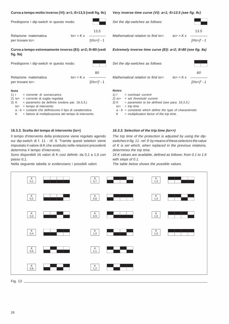
16.3.3. Scelta del tempo di intervento (to>)
Il tempo d'intervento della protezione viene regolato agendosui dip-switch di f. 11 - rif. 9. Tramite questi selettori vieneimpostato il valore di K che sostituito nelle relazioni precedentidetermina il tempo d'intervento.Sono disponibili 16 valori di K così definiti: da 0,1 a 1,6 conpasso 0,1.Nella seguente tabella si evidenziano i possibili valori.
K1,3
K1,4
K1,5
K1,6
K0,1
K0,2
K0,3
K0,4
K0,5
K0,6
K0,7
K0,8
K0,9
K1,0
K1,1
K1,2
Fig. 13
Very inverse time curve (VI): a=1; ß=13.5 (see fig. 9c)
Set the dip-switches as follows:
13.5Mathematical relation to find to>: to> = K x
[I/Io>]1 - 1
Extremely inverse time curve (EI): a=2; ß=80 (see fig. 9a)
Set the dip-switches as follows:
80Mathematical relation to find to>: to> = K x
[I/Io>]2 - 1
Notes1) I = overload current2) Io> = set threshold current3) K = parameter to be defined (see para. 16.3.3.) to> = trip time a - b = constants which define the type of characteristic K = multiplication factor of the trip time.
16.3.3. Selection of the trip time (to>>)
The trip time of the protection is adjusted by using the dip-switches in fig. 11 - ref. 9: by means of these selectors the valueof K is set which, when replaced in the previous relations,determines the trip time.16 K values are available, defined as follows: from 0.1 to 1.6with steps of 0.1.The table below shows the possible values.
29
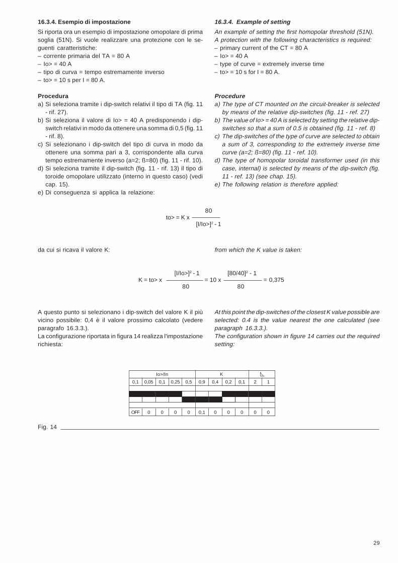
16.3.4. Esempio di impostazione
Si riporta ora un esempio di impostazione omopolare di primasoglia (51N). Si vuole realizzare una protezione con le se-guenti caratteristiche:– corrente primaria del TA = 80 A– Io> = 40 A– tipo di curva = tempo estremamente inverso– to> = 10 s per I = 80 A.
Proceduraa) Si seleziona tramite i dip-switch relativi il tipo di TA (fig. 11
- rif. 27).b) Si seleziona il valore di Io> = 40 A predisponendo i dip-
switch relativi in modo da ottenere una somma di 0,5 (fig. 11- rif. 8).
c) Si selezionano i dip-switch del tipo di curva in modo daottenere una somma pari a 3, corrispondente alla curvatempo estremamente inverso (a=2; ß=80) (fig. 11 - rif. 10).
d) Si seleziona tramite il dip-switch (fig. 11 - rif. 13) il tipo ditoroide omopolare utilizzato (interno in questo caso) (vedicap. 15).
e) Di conseguenza si applica la relazione:
80to> = K x
[I/Io>]2 - 1
da cui si ricava il valore K:
[I/Io>]2 - 1 [80/40]2 - 1K = to> x = 10 x = 0,375
80 80
A questo punto si selezionano i dip-switch del valore K il piùvicino possibile: 0,4 è il valore prossimo calcolato (vedereparagrafo 16.3.3.).La configurazione riportata in figura 14 realizza l'impostazionerichiesta:
Io>/In
0,1 0,05 0,1 0,25 0,5 0,9 0,4 0,2 0,1 2 1
K
OFF 0 0 0 0 0,1 0 0 0 0 0
Fig. 14
16.3.4. Example of setting
An example of setting the first homopolar threshold (51N).A protection with the following characteristics is required:– primary current of the CT = 80 A– Io> = 40 A– type of curve = extremely inverse time– to> = 10 s for I = 80 A.
Procedurea) The type of CT mounted on the circuit-breaker is selected
by means of the relative dip-switches (fig. 11 - ref. 27)b) The value of Io> = 40 A is selected by setting the relative dip-
switches so that a sum of 0.5 is obtained (fig. 11 - ref. 8)c) The dip-switches of the type of curve are selected to obtain
a sum of 3, corresponding to the extremely inverse timecurve (a=2; ß=80) (fig. 11 - ref. 10).
d) The type of homopolar toroidal transformer used (in thiscase, internal) is selected by means of the dip-switch (fig.11 - ref. 13) (see chap. 15).
e) The following relation is therefore applied:
from which the K value is taken:
At this point the dip-switches of the closest K value possible areselected: 0.4 is the value nearest the one calculated (seeparagraph 16.3.3.).The configuration shown in figure 14 carries out the requiredsetting:
30
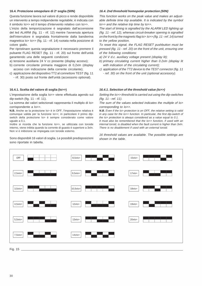
16.4. Protezione omopolare di 2a soglia (50N)
Questa funzione lavora sul valore di picco e rende disponibileun intervento a tempo indipendente regolabile; è indicata conil simbolo Io>> ed il tempo d'intervento relativo con to>>.L'inizio della temporizzazione è segnalato dall'accensionedel led ALARM (fig. 11 - rif. 12) mentre l'avvenuta aperturadell'interruttore è segnalata frontalmente dalla bandierinamagnetica Io> Io>> (fig. 11 - rif. 14) ruotata nella posizione dicolore giallo.Per ripristinare questa segnalazione è necessario premere ilpulsante FLAG RESET (fig. 11 - rif. 20) sul fronte dell'unitàgarantendo una delle seguenti condizioni:a) tensione ausiliaria 24 V cc presente (display acceso);b) corrente circolante primaria maggiore di 0,2xIn (display
acceso con indicazione della corrente circolante);c) applicazione del dispositivo TT2 al connettore TEST (fig. 11
- rif. 30) posto sul fronte dell'unità (accessorio optional).
16.4.1. Scelta del valore di soglia (Io>>)
L'impostazione della soglia Io>> viene effettuata agendo suidip-switch (fig. 11 - rif. 11).La somma dei valori selezionati rappresenta il multiplo di Io>corrispondente a Io>>.N.B. Anche se la protezione Io> è in OFF, l'impostazione relativa ècomunque valida per la funzione Io>>; in particolare il primo dip-switch della protezione Io> è sempre considerato come valoreuguale a 0,1.Inoltre si ricorda che la funzione Io>>, se utilizzata con toroideinterno, viene inibita quando la corrente di guasto è superiore a 3xIn.Non vi è inibizione se impiegata con toroide esterno.
Sono disponibili 16 valori di soglia. Le possibili predisposizionisono riportate in tabella.
OFF
2,5xIo>
3,5xIo>
4,5xIo>
5,5xIo>
7,5xIo>
8,5xIo>
9,5xIo>
10,5xIo>
12xIo>
13xIo>
14xIo>
15xIo>
17xIo>
18xIo>
19xIo>
20xIo>
Fig. 15
16.4. 2nd threshold homopolar protection (50N)
This function works on the peak value and makes an adjust-able definite time trip available. It is indicated by the symbolIo>> and the relative trip time by to>>.The start of timing is signalled by the ALARM LED lighting up(fig. 11 - ref. 12), whereas circuit-breaker opening is signalledon the front by the magnetic flag Io> Io>> (fig. 11 - ref. 14) turnedto the yellow position.To reset this signal, the FLAG RESET pushbutton must bepressed (fig. 11 - ref. 20) on the front of the unit, ensuring oneof the following conditions:a) 24 V d.c. auxiliary voltage present (display lit);b) primary circulating current higher than 0.2xIn (display lit
with indication of the circulating current);c) application of the TT2 device to the TEST connector (fig. 11
- ref. 30) on the front of the unit (optional accessory).
16.4.1. Selection of the threshold value (Io>>)
Setting the Io>> threshold is carried out using the dip-switches(fig. 11 - ref. 11).The sum of the values selected indicates the multiple of Io>corresponding to Io>>.N.B. Even if the Io> protection is on OFF, the relative setting is validin any case for the Io>> function. In particular, the first dip-switch ofthe Io> protection is always considered as a value equal to 0.1.It must also be remembered that the Io>> function, if used with aninternal toroid, is disabled when the fault current is higher than 3xIn.There is no disablement if used with an external toroid.
16 threshold values are available. The possible settings areshown in the table.

31
16.4.2. Scelta del tempo di intervento (to>>)
La funzione di protezione Io>> ha un intervento a tempoindipendente regolabile in 32 valori definiti dalla impostazionedei dip-switch relativi (fig. 11 - rif. 12). I valori disponibili sonocompresi tra 0,05 s e 1,55 s con passo di 0,05 s.Nella seguente tabella riportiamo le possibili predisposizionidei dip-switch.
Fig. 16
0,05 to>>
0,10to>>
0,15to>>
0,20to>>
0,25to>>
0,30to>>
0,35 to>>
0,40to>>
0,45to>>
0,50to>>
0,55to>>
0,60 to>>
0,65to>>
0,70to>>
0,75to>>
0,80to>>
0,80to>>
0,85to>>
0,90to>>
0,95to>>
1,00to>>
1,05to>>
1,10to>>
1,15to>>
1,20to>>
1,25to>>
1,30to>>
1,35to>>
1,40 to>>
1,45to>>
1,50to>>
1,55to>>
16.4.2. Selection of the trip time (to>>)
The function of protection Io>> has an adjustable definite timetrip, with 32 values defined by the relative dip-switch setting(fig. 11 - ref. 12). The values available are from 0.05 s to 1.55s with steps of 0.05 s.The table below shows the possible dip-switch settings.

32
16.4.3. Esempio di impostazione
Si riporta ora un esempio di impostazione della protezioneomopolare di 2a soglia (50N).Si vuole realizzare una protezione con le seguenti caratteri-stiche:– l'interruttore in oggetto monta TA da 80 A ed è privo di toroide
esterno– Io> = 40 A– Io>> = 300 A– to>> = 0,2 s.a) Si seleziona tramite i dip-switch relativi il tipo di TA montato
sull'interruttore (fig. 11 - rif. 27).b) Si seleziona il valore Io> = 40 A predispondendo i dip-
switch relativi in modo da ottenere la somma 0,5 (fig. 11 -rif. 8).
c) Si calcola il rapporto Io>> / Io>, cioè, 300 A / 40 A = 7,5.Si selezionano i dip-switch relativi alla funzione Io<< inmodo tale che la somma sia 7,5 (fig. 11 - rif. 11).
d) Si seleziona il tempo desiderato to>> = 0,2 s agendo sui dip-switch relativi (fig. 11 - rif. 12).
e) Si seleziona tramite il dip-switch (fig. 11 - rif. 13) il tipo ditoroide omopolare (interno in questo caso) (vedi cap. 15).
La configurazione riportata in figura 17 realizza l'impostazionerichiesta.
Fig. 17
17. Connessioni unitàLegenda delle connessioni unità in riferimento alla fig. 18 conrelative descrizioni:
XK1 XK31 Inizio fase L1 1 Solenoide d'apertura (+)2 Fine fase L1 2 Solenoide d'apertura (-)3 Inizio fase L24 Fine fase L2 XK55 Inizio fase L3 1 Non utilizzato6 Fine fase L3 2 Comando di apertura a distanza (a)7 Inizio toroide esterno 3 Non utilizzato8 Fine toroide esterno 4 Non utilizzato
5 Non utilizzatoXK2 6 Contatto bistabile SRE (a)1 Ingresso Vaux (+) 7 Contatto bistabile SRE (b)2 Ingresso Vaux (-) 8 Contatto bistabile µP (a)3 Non utilizzato 9 Contatto bistabile µP (b)4 Non utilizzato 10 Comando di apertura a distanza (b)
Fig. 18
Io>>
Io>
OFF 0 0 0 0 0,05 0 0 0 0
2,5 1 2 5 9,5 0,8 0,4 0,2 0,1 0,05
INT
1234
5678
XK1
1
2
1
2
3
4
XK3
XK2 1234678910
XK5
to>> Tor.
EXT
16.4.3. Example of setting
An example of setting the second homopolar threshold (50N)is now given.A protection with the following characteristics is required:– the circuit-breaker in question has a 80 A CT mounted and
does not have an external toroidal transformer– Io> = 40 A– Io>> = 300 A– to>> = 0.2 s.a) The type of CT mounted on the circuit-breaker is selected
by means of the relative dip-switches (fig. 11 - ref. 27)b) The value of Io> = 40 A is selected by setting the relative dip-
switches so that a sum of 0.5 is obtained (fig. 11 - ref. 8)c) The Io>> / Io> relation is calculated, i.e. 300 A / 40 A = 7.5.
The dip-switches relative to the Io<< function are selectedso that the sum is 7.5 (fig. 11 - ref. 11).
d) The desired time to>> = 0.2 s is selected by using the relativedip-switches (fig. 11 - ref. 12).
e) The type of homopolar toroidal transformer used (in thiscase, internal) is selected by means of the dip-switch (fig.11 - ref. 13) (see chap. 15).
The configuration shown in figure 17 carries out the requiredsetting.
XK1 XK31 Start of L1 phase 1 Opening solenoid (+)2 End of L1 phase 2 Opening solenoid (-)3 Start of L2 phase4 End of L2 phase XK55 Start of L3 phase 1 Not used6 End of L3 phase 2 Remote opening control (a)7 Start of external toroid 3 Not used8 End of external toroid 4 Not used
5 Not usedXK2 6 Bistable contact SRE (a)1 Input Vaux (+) 7 Bistable contact SRE (b)2 Input Vaux (-) 8 Bistable contact µP(a)3 Not used 9 Bistable contact µP(b)4 Not used 10 Remote opening control (b)
17. Unit connectionsCaption to the unit connections with reference to fig. 18 withrelative descriptions:

33
18. Altre informazioni
Ulteriori informazioni sono reperibili ai capitoli precedenti inquanto sono comuni all'unità PR512/P (50-51).Nell'elenco seguente sono indicati i riferimenti relativi.
• Schema elettrico circuitale par. 4.1.
• Curve tempo-corrente cap. 5
• Alimentazione ausiliaria cap. 6
• Contatti di segnalazione cap. 7
• Comando di apertura a distanza cap. 8
• Esecuzioni e fissaggio cap. 9
• Condizioni ambientali cap. 10
• Compatibilità elettromagnetica cap. 11
• Dati tecnici cap. 12
• Note e raccomandazioni cap. 13
18. Other information
Further information can be found in the previous chapters asthey also refer to the PR512/P (50-51) unit.The relative references are given in the list below.
• Electrical circuit diagram para. 4.1.
• Time-current curves chap. 5
• Auxiliary power supply chap. 6
• Signalling contacts chap. 7
• Remote opening control chap. 8
• Versions and fixing chap. 9
• Ambient conditions chap. 10
• Electromagnetic compatibility chap. 11
• Technical data chap. 12
• Notes and recommendations chap. 13
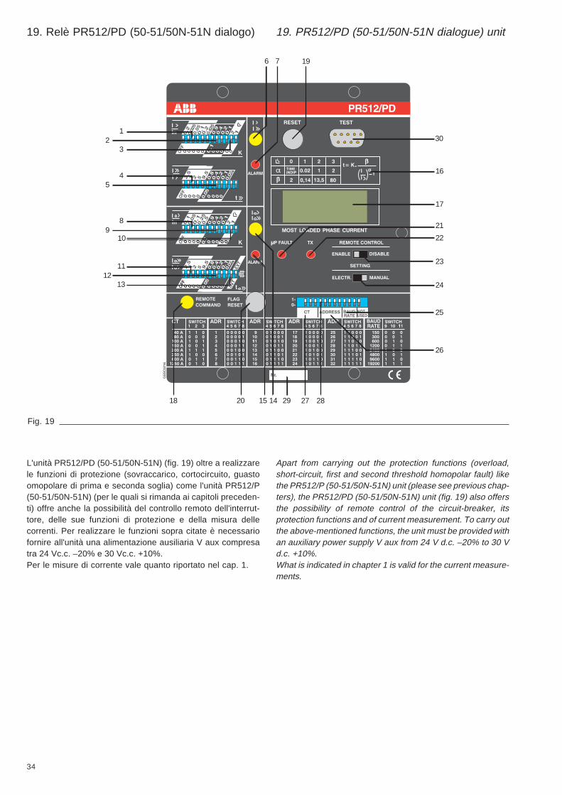
34
19
30
15 14 292018
89
11
1312
45
12
3
10
26
27 28
25
22
21
23
17
16
24
6 7
Fig. 19
19. Relè PR512/PD (50-51/50N-51N dialogo) 19. PR512/PD (50-51/50N-51N dialogue) unit
L'unità PR512/PD (50-51/50N-51N) (fig. 19) oltre a realizzarele funzioni di protezione (sovraccarico, cortocircuito, guastoomopolare di prima e seconda soglia) come l'unità PR512/P(50-51/50N-51N) (per le quali si rimanda ai capitoli preceden-ti) offre anche la possibilità del controllo remoto dell'interrut-tore, delle sue funzioni di protezione e della misura dellecorrenti. Per realizzare le funzioni sopra citate è necessariofornire all'unità una alimentazione ausiliaria V aux compresatra 24 Vc.c. –20% e 30 Vc.c. +10%.Per le misure di corrente vale quanto riportato nel cap. 1.
Apart from carrying out the protection functions (overload,short-circuit, first and second threshold homopolar fault) likethe PR512/P (50-51/50N-51N) unit (please see previous chap-ters), the PR512/PD (50-51/50N-51N) unit (fig. 19) also offersthe possibility of remote control of the circuit-breaker, itsprotection functions and of current measurement. To carry outthe above-mentioned functions, the unit must be provided withan auxiliary power supply V aux from 24 V d.c. –20% to 30 Vd.c. +10%.What is indicated in chapter 1 is valid for the current measure-ments.

35
Legenda1 Dip-switch per la predisposizione della soglia di intervento della
protezione I>2 Dip-switch per la predisposizione della temporizzazione K della
protezione I>3 Dip-switch per la predisposizione del tipo di curva (DT, NI, VI,
EI) della protezione I>4 Dip-switch per la predisposizione della soglia di intervento della
protezione I>>5 Dip-switch per la predisposizione del tempo di intervento t>>
della protezione I>>6 Bandierina magnetica bistabile di segnalazione protezione I> o
I>> intervenuta7 Led di segnalazione temporizzazione in corso protezioni I> o
I>>8 Dip-switch per la predisposizione della soglia di intervento della
protezione Io>9 Dip-switch per la predisposizione della temporizzazione K della
protezione Io>10 Dip-switch per la predisposizione del tipo di curva (DT, NI, VI,
EI) della protezione Io>11 Dip-switch per la predisposizione della soglia di intervento della
protezione Io>>12 Dip-switch per la predisposizione del tempo di intervento to>>
della protezione Io>>13 Dip-switch per la predisposizione del tipo di toroide omopolare
(interno/esterno)14 Bandierina magnetica bistabile di segnalazione protezione Io> o
Io>> intervenuta15 Led di segnalazione temporizzazione in corso protezioni Io> o
Io>>16 Relazione tempo-corrente secondo IEC 255-417 Display visualizzante la corrente della fase più caricata18 Bandierina magnetica bistabile segnalazione di avvenuta aper-
tura a distanza dell'interruttore19 Pulsante di RESET del microprocessore e dei relè bistabili di
segnalazione SRE e µP FAULT20 Pulsante di reset delle bandierine magnetiche bistabili (riferi-
menti 6, 14, 18)21 Led di segnalazione microprocessore guasto (µP FAULT)22 Led di segnalazione comunicazione seriale attiva23 Commutatore inibizione comando remoto di chiusura e apertura
da sistema24 Commutatore per l'attivazione della programmazione manuale
o elettronica25 Dip-switch per la predisposizione della velocità della trasmis-
sione seriale (baud rate)26 Dip-switch per la predisposizione indirizzo dell'unità27 Dip-switch predisposizione calibro trasformatori amperometrici28 Tappo copri dip-switch e targhetta “In” calibro TA29 Nr. di matricola unità30 Connettore per TEST
Caption1 Dip-switch for setting the trip threshold of protection I>2 Dip-switch for setting the time-delay K of protection I>3 Dip-switch for setting the type of curve (DT, NI, VI, EI) of
protection I>4 Dip-switch for setting the trip threshold of protection I>>5 Dip-switch for setting the trip time t>> of protection I>>6 Bistable magnetic flag indicating protection I> or I>> tripped7 LED indicating time-delay elapsing protection I> or I>>8 Dip-switch for setting the trip threshold of protection Io>9 Dip-switch for setting the time delay K of protection Io>
10 Dip-switch for setting the type of curve (DT, NI, VI, EI) ofprotection Io>
11 Dip-switch for setting the tripping threshold of protection Io>>12 Dip-switch for setting the trip time to>> of protection Io>>13 Dip-switch for setting the type of toroidal homopolar trans-
former (internal/external)14 Bistable magnetic flag indicating protection Io> or Io>> tripped15 LED indicating time-delay elapsing protection Io> or Io>>16 Time-current relation in conformity with IEC 255-417 Display showing the phase current with the highest load18 Bistable magnetic flag indicating remote opening of circuit-
breaker19 RESET pushbutton for microprocessor and bistable relays
signalling SRE and µP FAULT20 Reset pushbutton for bistable magnetic flags (components 6,
14, 18)21 LED indicating microprocessor fault (µP FAULT)22 LED indicating serial communication active23 Change-over contact disabling remote system closing and
opening command24 Change-over contact activating manual or electronic program-
ming25 Dip-switch for setting serial transmission speed (baud rate)26 Dip-switch for setting unit address27 Dip-switch for setting rated current of current transformers28 Cover for CT rated current dip-switch and “In” plate29 Unit serial number30 TEST connector
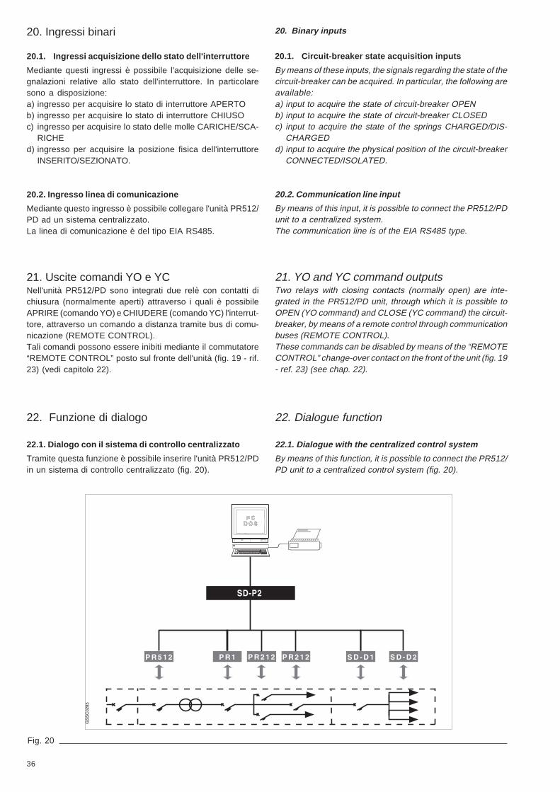
36
Fig. 20
20. Ingressi binari
20.1. Ingressi acquisizione dello stato dell'interruttore
Mediante questi ingressi è possibile l'acquisizione delle se-gnalazioni relative allo stato dell'interruttore. In particolaresono a disposizione:a) ingresso per acquisire lo stato di interruttore APERTOb) ingresso per acquisire lo stato di interruttore CHIUSOc) ingresso per acquisire lo stato delle molle CARICHE/SCA-
RICHEd) ingresso per acquisire la posizione fisica dell'interruttore
INSERITO/SEZIONATO.
20.2. Ingresso linea di comunicazione
Mediante questo ingresso è possibile collegare l'unità PR512/PD ad un sistema centralizzato.La linea di comunicazione è del tipo EIA RS485.
21. Uscite comandi YO e YCNell'unità PR512/PD sono integrati due relè con contatti dichiusura (normalmente aperti) attraverso i quali è possibileAPRIRE (comando YO) e CHIUDERE (comando YC) l'interrut-tore, attraverso un comando a distanza tramite bus di comu-nicazione (REMOTE CONTROL).Tali comandi possono essere inibiti mediante il commutatore“REMOTE CONTROL” posto sul fronte dell'unità (fig. 19 - rif.23) (vedi capitolo 22).
20. Binary inputs
20.1. Circuit-breaker state acquisition inputs
By means of these inputs, the signals regarding the state of thecircuit-breaker can be acquired. In particular, the following areavailable:a) input to acquire the state of circuit-breaker OPENb) input to acquire the state of circuit-breaker CLOSEDc) input to acquire the state of the springs CHARGED/DIS-
CHARGEDd) input to acquire the physical position of the circuit-breaker
CONNECTED/ISOLATED.
20.2. Communication line input
By means of this input, it is possible to connect the PR512/PDunit to a centralized system.The communication line is of the EIA RS485 type.
21. YO and YC command outputsTwo relays with closing contacts (normally open) are inte-grated in the PR512/PD unit, through which it is possible toOPEN (YO command) and CLOSE (YC command) the circuit-breaker, by means of a remote control through communicationbuses (REMOTE CONTROL).These commands can be disabled by means of the “REMOTECONTROL” change-over contact on the front of the unit (fig. 19- ref. 23) (see chap. 22).
22. Funzione di dialogo
22.1. Dialogo con il sistema di controllo centralizzato
Tramite questa funzione è possibile inserire l'unità PR512/PDin un sistema di controllo centralizzato (fig. 20).
22. Dialogue function
22.1. Dialogue with the centralized control system
By means of this function, it is possible to connect the PR512/PD unit to a centralized control system (fig. 20).

37
L'interfaccia seriale utilizzata è conforme allo standard IECRS485 e di conseguenza le connessioni devono essererealizzate rispettando le regole imposte da tale standard; aquesto proposito vedere i documenti (disponibili a richiesta):– 401517 esempi di distribuzione della comunicazione
seriale tipo EIA RS485– 601823 prescrizioni per la posa del cavo di comunicazio-
ne seriale tipo EIA RS485.Il protocollo utilizzato è ABB INSUM descritto nel documentoTN6567 (disponibile a richiesta).Lo standard EIA RS485 definisce un sistema di comunicazio-ne seriale differenziale, multi point che prevede un Master(unità centrale) e fino ad un massimo di 32 Slave.Di conseguenza ciascun slave (PR512/PD) deve essere indi-viduato attraverso un indirizzo distinto impostabile tramite dip-switch sul fronte dell'unità (fig. 19 - rif. 26). Non è permessoavere più unità con lo stesso indirizzo.La velocità di trasmissione è programmabile da un minimo di150 Baud (bit/s) ad un massimo di 19200 Baud tramite i dip-switch (fig. 20 - rif. 25).L'attività di trasmissione dell'unità con il sistema di controlloviene segnalata dal lampeggio del led TX (fig. 19 - rif. 22).
22.1.1. Dati trasmessi
L'unità PR512/PD è in grado di trasmettere le seguenti infor-mazioni:a) numero di manovre meccaniche dell'interruttoreb) parametri delle funzioni di protezionec) correnti di fase e omopolared) corrente della fase più caricatae) ìndicazione di bassa corrente (Low Load)f) ultima corrente interrottag) stato delle funzioni di protezione:1) normale funzionamento2) allarme (I>, I>>, Io>, Io>>)3) scattato relèh) stato del bus internoi) stato dell'interruttore:1) interruttore aperto o chiuso2) interruttore inserito o sezionato3) stato delle molle del comando scariche o cariche.
22.1.2. Dati ricevuti
L'unità PR512/PD può ricevere dal sistema di controllo cen-tralizzato i seguenti dati:a) tutti i parametri delle funzioni di protezioneb) comando di apertura dell'interruttorec) comando di chiusura dell'interruttore.
22.2. Inibizione comando apertura - chiusura
Mediante il commutatore “REMOTE CONTROL” posto sulfrontale dell'unità in posizione “DISABLE”, (fig. 19 - rif. 23)facilmente accessibile, è possibile l'inibizione dei comandi diapertura e chiusura dell'interruttore provenienti dal sistema dicontrollo centralizzato.
22.3. Impostazione parametri manualeo elettronica
Mediante il commutatore “SETTING” posto sul frontale del-l'unità (fig. 19 - rif. 24) è possibile attivare l'impostazione(relativamente a soglie e a curve) manuale (MANUAL), ope-rata mediante i dip-switch posti sul fronte dell'unità ol'impostazione elettronica (ELECTR), operata mediante siste-ma centralizzato.
The serial interface used complies with IEC RS485 Standardand consequently the connections must be made respectingthe rules imposed by that standard. With regard to this, see thefollowing documents (available on request):– 401517 examples of EIA RS485 type serial communica-
tion distribution– 601823 specifications for EIA RS485 type serial commu-
nication cable laying.The protocol used is ABB INSUM, described in documentTN6567 (available on request).The EIA RS485 standard defines a residual current serialcommunication system, with multi points with a Master (centralunit) and up to a maximum of 32 Slaves.Consequently each slave (PR512/PD) must be identified by adistinct address, which can be set by means of dip-switches onthe front of the unit (fig. 19 - ref. 26). There cannot be more thanone unit with the same address.The transmission speed can be programmed from a minimumof 150 Baud (bit/s) to a maximum of 19200 Baud by means ofthe dip-switches (fig. 20 - ref. 25).Transmission activity of the unit with the centralized controlsystem is signalled by the TX LED flashing (fig. 19 - ref. 22).
22.1.1. Transmitted data
The PR512/PD unit is able to transmit the following informa-tion:a) number of circuit-breaker mechanical operationsb) protection function parametersc) phase and homopolar currentsd) current of the phase with the highest loade) low current indication (Low Load)f) last interrupted currentg) state of the protection functions:1) normal operation2) alarm (I>, I>>, Io>, Io>>)3) relay trippedh) state of the internal busi) state of the circuit-breaker:1) circuit-breaker open or closed2) circuit-breaker connected or isolated3) state of the o. mechanism springs discharged or charged.
22.1.2. Data received
The PR512/PD unit can receive the following data from thecentralized control system:a) all the protection function parametersb) circuit-breaker opening commandc) circuit-breaker closing command.
22.2. Disabling the opening - closing command
By means of the “REMOTE CONTROL” change-over contacton the front of the unit being put in the easily accessible“DISABLE” position (fig. 19 - ref. 23), it is possible to disable thecircuit-breaker opening and closing commands coming fromthe centralized control system.
22.3. Setting the parameters manually or electronically
By means of the “SETTING” change-over contact on the frontof the unit (fig. 19 - ref. 24), it is possible to activate setting(regarding thresholds and curves) manually (MANUAL), oper-ated by means of the dip-switches placed on the front of the unitor electronically (ELECTR), operated by means of the central-ized system.

38
23. Esempio di impostazione dellacomunicazione seriale
0 0 0 0 0 0 0 0 0 0 0 0
1 1 1 1 1 1 1 1 1 1 1 1
CT ADDRESS BAUD RATE
Fig. 21
23. Example of serial communication setting
Ora vogliamo predisporre l'unità PR512/PD per il controllo dasistema centralizzato impostando una velocità di trasmissio-ne dati (Baud rate) di 9600 bit/s e l'indirizzo (Address) al Nr. 28.È necessario quindi predisporre i seguenti dip-switch (fig, 19- rif. 28) e (fig. 19 - rif. 25).
The PR512/PD unit must now be set for control from thecentralized system by setting a data transmission speed (Baudrate) of 9600 bit/s and the Address at no. 28.It is therefore necessary to set the following dip-switches (fig.19 - ref. 28) and (fig. 19 - ref. 25).
24. Connessioni unità
Legenda delle connessioni unità in riferimento alla fig. 22 conrelative descrizioni:
Fig. 22
XK11 Inizio fase L12 Fine fase L13 Inizio fase L24 Fine fase L25 Inizio fase L36 Fine fase L37 Inizio toroide esterno8 Fine toroide esterno
XK21 Ingresso Vaux (+)2 Ingresso Vaux (-)3 Non utilizzato4 Non utilizzato
XK31 Solenoide d'apertura (+)2 Solenoide d'apertura (-)
XK41 Contatto interruttore aperto2 Contatto interruttore chiuso3 Contatto interruttore inserito4 Comune contatti di segnala-
zione
1234
5678
XK1
1
2
1
2
3
4
XK3
XK2 XK5 1234678910
XK6
1234
XK4 1234678910
24. Unit connections
Caption to the unit connections with reference to fig. 22 and relativedescriptions:
XK11 Start of L1 phase2 End of L1 phase3 Start of L2 phase4 End of L2 phase5 Start of L3 phase6 End of L3 phase7 Start of external toroid8 End of external toroid
XK21 Input Vaux (+)2 Input Vaux (-)3 Not used4 Not used
XK31 Opening solenoid (+)2 Opening solenoid (-)
XK41 Circuit-breaker open contact2 Circuit-breaker closed
contact3 Circuit-breaker connected
contact
5 Comando BA (a)6 Contatto molle cariche7 Comando BC (a)8 Non utilizzato9 Comando BA (b)10Comando BC (b)
XK51 Non utilizzato2 Comando di apertura a distan-
za (a)3 Non utilizzato4 Non utilizzato5 Non utilizzato6 Contatto bistabile SRE (a)7 Contatto bistabile SRE (b)8 Contatto bistabile µP (a)9 Contatto bistabile µP (b)10Comando di apertura a distan-
za (b)
XK61 Uscita “A” seriale EIA RS4852 Uscita “B” seriale EIA RS4853 Equipotenzialità4 Non utilizzato
4 Common signalling contacts5 BA command (a)6 Springs charged contact7 BC command (a)8 Not used9 BA command (b)10BC command (b)
XK51 Not used2 Remote opening control (a)3 Not used4 Not used5 Not used6 Bistable contact SRE (a)7 Bistable contact SRE (b)8 Bistable contact μP (a)9 Bistable contact μP (b)10Remote opening control (b)
XK61 EIA RS485 serial “A” output
2 EIA RS485 serial “B” output
3 Equipotentiality4 Not used

39
25. Dati tecnici
Il consumo dell'unità PR512/PD è di 120 mA a 24 V cc.I contatti dei relè di comando YO e YC hanno le seguenticaratteristiche elettriche:– Massima corrente interrotta = 5 A– Massima tensione interrotta = 250 Vc.a., 130 V d.c.– Massimo carico interrotto a 48 V c.c.:
induttivo (L/R = / ms) = 25 Wresistivo = 50 W
– Massimo carico interrotto a 220 V c.a.:induttivo (cosϕ = 0,4) = 500 VAresistivo = 800 VA
– Isolamento contatto/contatto = 1000 V eff.– Isolamento contatto/bobina = 2000 V eff.
26. Note e raccomandazioni
Non sono ammesse prove di rigidità di alcun tipo di verificadell'isolamento a tutti gli ingressi e uscite (esclusi relè dicomando e segnalazione).
25. Technical data
The consumption of the PR512/PD unit is 120 mA at 24 V d.c.The YO and YC command relay contacts have the followingelectrical characteristics:– Maximum interrupted current = 5 A– Maximum interrupted voltage = 250 V a.c., 130 V d.c.– Maximum interrupted load at 48 V d.c.:
inductive (L/R = / ms) = 25 Wresistive = 50 W
– Maximum interrupted load at 220 V a.c.:inductive (cosϕ = 0.4) = 500 VAresistive = 800 VA
– Contact/contact insulation = 1000 V eff.– Contact/ coil insulation = 2000 V eff.
26. Notes and recommendations
No insulation verification rigidity tests of any type are allowedon all inputs and output (excluding command and signallingrelays).
27. Messa in servizio
Verificare che tutte le operazioni di messa in serviziosiano effettuate da personale con una qualifica suffi-ciente e una conoscenza adeguata della apparec-chiatura.Scollegare l’unità PR512 prima di effettuare qualsiasiprova di isolamento sull’impianto.
Prima della messa in servizio è necessario effettuare almenoil test di seguito descritto.
27.1. Test sganciatore a smagnetizzazione (Y03)
Attraverso questo test si verifica la funzionalità del micro-controllore e dello sganciatore a smagnetizzazione (Y03) cheagisce direttamente sul comando di apertura dell’interruttore.Il test dello sganciatore a smagnetizzazione può essere effet-tuato mediante il dispositivo di test TT2 applicato al connettoredi TEST ed opportunamente impostato (fig.1 rif. 30). Taleoperazione di test non genera la commutazione del relè disegnalazione di protezione intervenuta per massima corrente(K51/Y03).
27. Putting into service
Check that all the operations for putting into serviceare carried out by suitably qualified personnel withadequate knowledge of the apparatus.Disconnect the PR512 unit before carrying out anyinsulation test on the installation.
Before putting into service, at least the test described belowmust be carried out.
27.1. Demagnetisation release test (Y03)
The function of the microcontroller and demagnetisationrelease (Y03) is carried out by means of this test, which actsdirectly on the opening control of the circuit-breaker.The test on the demagnetisation release can be carried out bymeans of a test device TT2 applied to the TEST connector (fig.1 ref. 30). This test operation does not cause change-over ofthe signalling relay of protection tripped due to overcurrent(K51/Y03).
! !

40
Battery: 9V IEC SIZE: 6F22
PR512TEST
OPERATIONMODE1) Set the Dip-Switch
2) Insert the plug
3) Press TESTpushbuttonuntil the endof check
TRIP TEST
DEF. TIMEI> I>>TRIP
DEF. TIMEI> I>>TEST
OFF
1
A
A
A
B
3
B
A
A
--
2
A
B
B
--
4
B
B
A
--
PR511PR521TEST
TRIP TEST
RESET
OFF
1
A
A
B
3
B
A
--
2
A
B
--
4
--
--
--
1
B
A
2 3 4
Vista frontale dell’Unità di TestFront view of the TT2 test unit
Vista posteriore dell’Unità di Test TT2Rear view of the TT2 test unit
27.2. Funzione di TEST
Mediante l'accessorio TT2 (Unità di Test fornibile a richiesta)è possibile effettuare il TEST complessivo della funzionalità disgancio del relè (parte elettronica e solenoide di aperturaY03). L'unità di Test TT2, tramite il connettore a 9 PIN,consentedi effettuare il TEST delle funzioni 50-51 nella configurazionecon curva a tempo dipendente (DT).Il suddetto TEST può essere eseguito con solenoide di aper-tura Y03 attivato (TRIP) oppure disattivato (TEST).
Utilizzo dell'unità TT2
Porre il Dip Switch 1 in posizione A per abilitare il TT2 alfunzionamento; ciò permette anche l'alimentazione dell'unitàdiprova con conseguente accensione del display.In questo caso è anche possibile effettuare il reset hardwaredella protezione e il reset dei relè di segnalazione K51/Y03.Porre i Dip Switch 1 e 2 in posizione A e premere il pulsanteTESTper effettuare lo sgancio del solenoide di apertura Y03 con laconseguente apertura dell'interruttore.Porre i Dip Switch1e 3 in posizione A e premere il pulsanteTESTper effettuare il controllo delle funzioni I> e I>> (solo per lecurve a tempo fisso) ed iniziare la temporizzazione dellafunzione prescelta con il successivo sgancio del solenoide diapertura Y03 e la conseguente apertura dell'interruttore.Porre i Dip Switch 1, 3 e 4 in posizione A se si desidera inibireil comando di apertura del solenoide di apertura Y03 duranteil controllo delle funzioni I> e I>>.Per effettuare l'autodiagnosi della carica della batteria e delcorretto funzionamento del TT2, porre il Dip Switch 1 inposizione A, premere il pulsante CHECK e verificare l'accen-sione del LED. Se il LED risulta spento è necessario sostituirela batteria.
28. Controlli periodici
Si consiglia di ripetere, con cadenza annuale e per almenocinque volte, il test descritto nel paragrafo precedente.
8. Periodic checks
It is advisable to repeat the test described in the paragraphabove annually and at least five times.
Use of the TT2 unit
Put Dip-Switch 1 in position A to enable TT2 for operation. Thisalso enables the test unit power supply with the displaytherefore lighting up.In this case, it is also possible to carry out hardware resettingof the protection and resetting of the K51/YO3 signallingrelays.Put Dip-Switches 1 and 2 in position A and press the TESTpushbutton to release the YO3 opening solenoid with conse-quent circuit-breaker opening.Put Dip-Switches 1 and 3 in position A and press the TESTpushbutton to check functions I> and I>> (only for the fixed timecurves) and start selected function timing with subsequentrelease of the YO3 opening solenoid and consequent circuit-breaker opening.Put Dip-Switches 1, 3 and 4 in position A if the YO3 openingsolenoid opening command is to be disabled during checkingof function I> and I>>.To carry out self-diagnosis of the battery charge and correctoperation of the TT2, put Dip-Switch 1 in position A, press theCHECK pushbutton and verify that the LED lights up. If the LEDis off, the battery must be replaced.
27.2 TEST function
By using the TT2 accessory (Test Unit supplied on request), theoverall functionality TEST of the relay release (electronic partand YO3 opening solenoid) can be carried out. By means ofthe 9 PIN connector, the TT2 Test unit allows the TEST to becarried out on functions 50-51 in the configuration with definitetime curve (DT).The above-mentioned TEST can be carried out with the YO3opening solenoid activated (TRIP) or de-activated (TEST).


Per maggiori informazioni contattare: For more information please contact:
ABB S.p.A. Power Products DivisionUnità Operativa Sace-MVVia Friuli, 4I-24044 DalmineTel.: +39 035 6952 111Fax: +39 035 6952 874E-mail: [email protected]
ABB AG Calor Emag Medium Voltage Products Oberhausener Strasse 33 Petzower Strasse 8 D-40472 Ratingen D-14542 Glindow Phone: +49(0)2102/12-1230, Fax: +49(0)2102/12-1916 E-mail: [email protected]
www.abb.com
Dati e immagini non sono impegnativi. In funzione dello sviluppo tecnico e dei prodotti, ci riserviamo il diritto di modificare il contenuto di questo documento senza alcuna notifica.
The data and illustrations are not binding. We reserve the right to make changes without notice in the course of technical development of the product.
Copyright 2010 ABB. All rights reserved.
6491
72/0
02 -
Rev
. C,
it-en
- In
stru
ctio
n M
anua
l 201
0.02
(P
R51
2) (
gs)