guidelines for using decision sight distance at … for using decision sight distance at signalized...
TRANSCRIPT

1. Report No. FHWA/TX-05/0-4084-P2
2. Government Accession No.
3. Recipient's Catalog No. 5. Report Date September 2004
4. Title and Subtitle GUIDELINES FOR USING DECISION SIGHT DISTANCE AT
IGNALIZED INTERSECTIONS NEAR VERTICAL CURVES S 6. Performing Organization Code
7. Author(s) Paul A. Barricklow and Marc S. Jacobson
8. Performing Organization Report No. Product 0-4084-P2 10. Work Unit No. (TRAIS)
9. Performing Organization Name and Address Texas Transportation Institute The Texas A&M University System College Station, Texas 77843-3135
11. Contract or Grant No. Project 0-4084 13. Type of Report and Period Covered Product
12. Sponsoring Agency Name and Address Texas Department of Transportation Research and Technology Implementation Office P. O. Box 5080 Austin, Texas 78763-5080
14. Sponsoring Agency Code
15. Supplementary Notes Project performed in cooperation with the Texas Department of Transportation and the Federal Highway Administration. Project Title: Countermeasures to Reduce Crashes at Signalized Intersections near Vertical Curves URL: http://tti.tamu.edu/documents/0-4084-P2.pdf 16. Abstract
Whereas standard roadway design ensures that stopping sight distance (SSD) is provided at all locations along a roadway, there is no standard established for when decision sight distance (DSD) is needed with respect to traffic signals. A “reduced decision zone” (RDZ) was identified in the research as the location along a roadway with a vertical curve and a traffic signal beyond the curve where SSD is provided but DSD is not. Essentially, motorists within the RDZ are provided with SSD for unexpected stopping but are not provided with the added decision-making and response time that DSD might otherwise provide as they approach the vertical curve and the downstream traffic signal. Contained within this report are techniques for determining whether an RDZ exists along an existing roadway or has the potential to exist in a proposed design. It is suggested that intersections not be located within the RDZ.
17. Key Words Signal, Vertical Curve, Sight Distance
18. Distribution Statement
19. Security Classif.(of this report)
20. Security Classif.(of this page)
21. No. of Pages 20
22. Price
Form DOT F 1700.7 (8-72) Reproduction of completed page authorized

GUIDELINES FOR USING DECISION SIGHT DISTANCE AT SIGNALIZED INTERSECTIONS NEAR VERTICAL CURVES
by
Paul A. Barricklow Assistant Transportation Researcher
Texas Transportation Institute
and
Marc S. Jacobson, P.E. Assistant Research Engineer
Texas Transportation Institute
Product 0-4084-P2 Project 0-4084
Project Title: Countermeasures to Reduce Crashes at Signalized Intersections near Vertical Curves
Performed in cooperation with the Texas Department of Transportation
and the Federal Highway Administration
September 2004
TEXAS TRANSPORTATION INSTITUTE The Texas A&M University System College Station, Texas 77843-3135

DISCLAIMER The contents of this report reflect the views of the authors, who are solely responsible for the facts and accuracy of the data, opinions, and conclusions presented herein. The contents do not necessarily reflect the official views or policies of the Texas Department of Transportation (TxDOT) or the Federal Highway Administration (FHWA). This report does not constitute a standard or regulation, and its contents are not intended for construction, bidding, or permit purposes. The names of specific products or manufacturers listed herein do not imply endorsement of these products or manufacturers. The engineer in charge of this project was Marc S. Jacobson, P.E. (Texas #89335). The United States Government and the State of Texas do not endorse products or manufacturers. Trade or manufacturers’ names may appear herein solely because they are considered essential to the object of this report.
v
ACKNOWLEDGMENTS This research was conducted during a two-year project under a cooperative research program between the Texas Transportation Institute (TTI), TxDOT, and FHWA. Imelda Barrett of the TxDOT Austin District was the project director (PD). Other TxDOT members of the Project Monitoring Committee included Brian Van De Walle, David Mitchell, Chuck Ansley, Arnold Ramirez (retired), Bill Tucker (retired), and Peter Eng. Ali Mozdbar of the City of Austin, Texas, also served on the Project Monitoring Committee. Tom Beeman of the Traffic Operations Division was the program coordinator, and Wade Odell of TxDOT’s Research and Technology Implementation Office was an active participant in project management meetings. Angelia Parham, Michael Martello, Gary Barricklow, Mark Wooldridge, and Hassan Charara of TTI also contributed to the materials used in this report. Angelia Parham and Mike Martello helped with literature and site reviews, Mark Wooldridge provided guidance on data collection techniques, Hassan Charara assisted with field implementation, and Gary Barricklow conducted field studies.
vi
TABLE OF CONTENTS
Page LIST OF FIGURES ................................................................................................................... viii LIST OF TABLES .......................................................................................................................ix GUIDELINES FOR USING DECISION SIGHT DISTANCE AT SIGNALIZEDINTERSECTIONS NEAR VERTICAL CURVES.................................................................... 1 INTRODUCTION..................................................................................................................... 1 EXISTING PRACTICE AND GUIDELINES ....................................................................... 1
STOPPING SIGHT DISTANCE............................................................................................. 1 DECISION SIGHT DISTANCE ............................................................................................. 1 EXISTING VERTICAL CURVE DESIGN ............................................................................ 3
PROPOSED GUIDELINES FOR USING DECISION SIGHT DISTANCE IN INTERSECTION DESIGN ..................................................................................................... 5
GUIDELINES FOR USING DECISION SIGHT DISTANCE IN INTERSECTION OPERATIONS/SAFETY ANALYSIS.................................................................................... 6
REFERENCES.............................................................................................................................. 9
vii

LIST OF FIGURES
Page Figure 1. Design of Typical Vertical Curve from TxDOT Roadway Design Manual (2)............. 4 Figure 2. Minimum Lengths of Vertical Curves to Provide Stopping Sight Distance from
TxDOT Roadway Design Manual (2)........................................................................... 5 Figure 3. Reduced Decision Zone Location for Rural Roadway Applications. ............................ 7 Figure 4. Reduced Decision Zone Location for Urban Roadway Applications. ........................... 8
viii

LIST OF TABLES
Page Table 1. Recommended Stopping Sight Distance Guidelines Provided by AASHTO (1). ........... 2 Table 2. Decision Sight Distance Guidelines Provided by AASHTO (1). .................................... 3
ix


GUIDELINES FOR USING DECISION SIGHT DISTANCE AT SIGNALIZED INTERSECTIONS NEAR VERTICAL CURVES
INTRODUCTION
As a motorist travels any stretch of roadway, there is a certain distance ahead of the motorist’s vehicle that can be clearly seen. This distance is known as the sight distance at a particular location along the roadway. The sight distance at a point is dependent upon the direction of travel of the vehicle.
In order to safely travel a given route, a motorist must be able to see a potentially harmful object or situation, comprehend the required action needed to avoid a collision, and take the appropriate action. The combination of these three steps results in guidelines for minimum sight distance required in certain situations. These guidelines are provided in A Policy on Geometric Design of Highways and Streets, better known as the Green Book, published by the American Association of State Highway and Transportation Officials (AASHTO) (1).
EXISTING PRACTICE AND GUIDELINES
Stopping Sight Distance
The most basic sight distance guideline provided is stopping sight distance (SSD). The SSD is the distance required, at a given speed, for a motorist to recognize a stationary object in the roadway and come to a complete stop prior to striking the object. Based on previous studies, AASHTO recommends using a perception-reaction time of 2.5 seconds and a deceleration rate of 11 feet per second squared. In addition, a driver’s eye height of 3.5 feet and an object height of 2.0 feet are recommended. Using these recommended values, the design guidelines for required SSD at various speeds are shown in Table 1 (1).
Decision Sight Distance
While the provision of SSD should be sufficient in most cases for the average driver to comprehend a possible conflict and appropriately react, there are circumstances where additional sight distance is needed. When additional distance is necessary, the guidelines for decision sight distance (DSD) should be used. The TxDOT Roadway Design Manual defines DSD as follows:
Decision sight distance is the distance required for a driver to detect an unexpected or otherwise difficult-to-perceive information source, recognize the source, select an appropriate speed and path, and initiate and complete the required maneuver safely and efficiently (2).
1
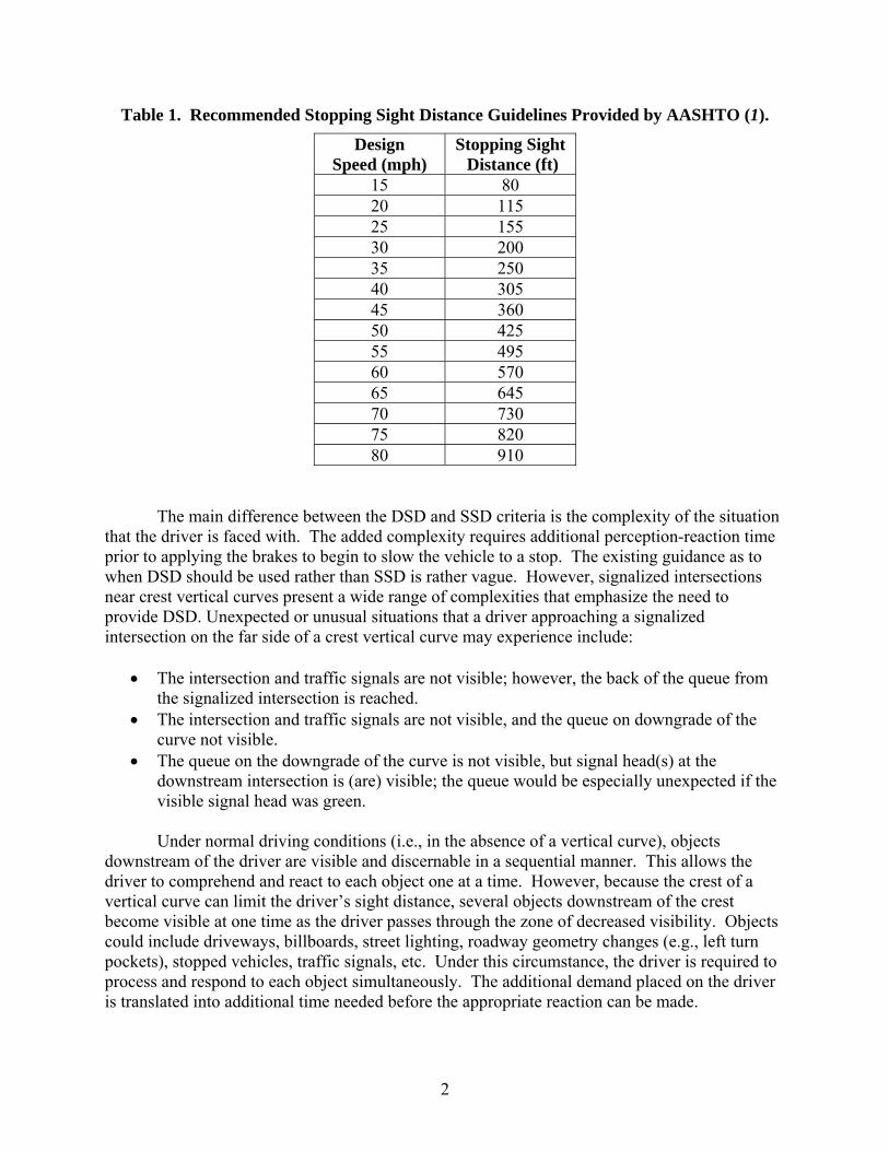
Table 1. Recommended Stopping Sight Distance Guidelines Provided by AASHTO (1).
Design Speed (mph)
Stopping Sight Distance (ft)
15 80 20 115 25 155 30 200 35 250 40 305 45 360 50 425 55 495 60 570 65 645 70 730 75 820 80 910
The main difference between the DSD and SSD criteria is the complexity of the situation that the driver is faced with. The added complexity requires additional perception-reaction time prior to applying the brakes to begin to slow the vehicle to a stop. The existing guidance as to when DSD should be used rather than SSD is rather vague. However, signalized intersections near crest vertical curves present a wide range of complexities that emphasize the need to provide DSD. Unexpected or unusual situations that a driver approaching a signalized intersection on the far side of a crest vertical curve may experience include:
• The intersection and traffic signals are not visible; however, the back of the queue from the signalized intersection is reached.
• The intersection and traffic signals are not visible, and the queue on downgrade of the curve not visible.
• The queue on the downgrade of the curve is not visible, but signal head(s) at the downstream intersection is (are) visible; the queue would be especially unexpected if the visible signal head was green.
Under normal driving conditions (i.e., in the absence of a vertical curve), objects
downstream of the driver are visible and discernable in a sequential manner. This allows the driver to comprehend and react to each object one at a time. However, because the crest of a vertical curve can limit the driver’s sight distance, several objects downstream of the crest become visible at one time as the driver passes through the zone of decreased visibility. Objects could include driveways, billboards, street lighting, roadway geometry changes (e.g., left turn pockets), stopped vehicles, traffic signals, etc. Under this circumstance, the driver is required to process and respond to each object simultaneously. The additional demand placed on the driver is translated into additional time needed before the appropriate reaction can be made.
2
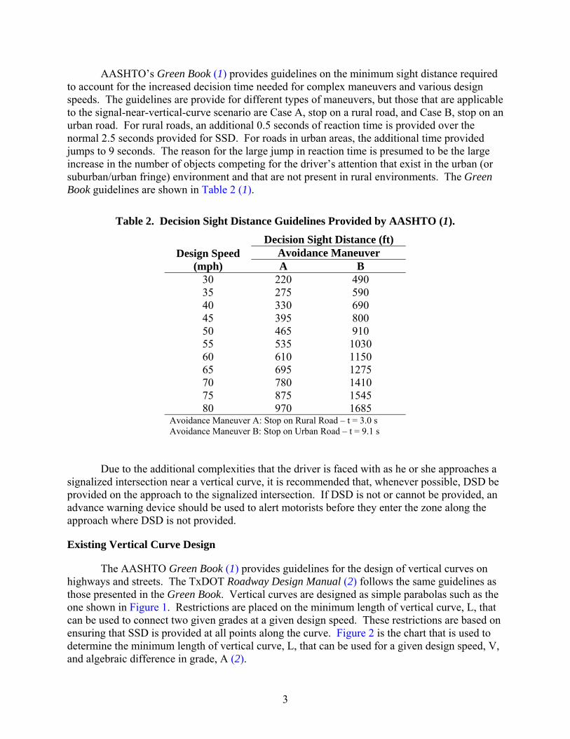
AASHTO’s Green Book (1) provides guidelines on the minimum sight distance required to account for the increased decision time needed for complex maneuvers and various design speeds. The guidelines are provide for different types of maneuvers, but those that are applicable to the signal-near-vertical-curve scenario are Case A, stop on a rural road, and Case B, stop on an urban road. For rural roads, an additional 0.5 seconds of reaction time is provided over the normal 2.5 seconds provided for SSD. For roads in urban areas, the additional time provided jumps to 9 seconds. The reason for the large jump in reaction time is presumed to be the large increase in the number of objects competing for the driver’s attention that exist in the urban (or suburban/urban fringe) environment and that are not present in rural environments. The Green Book guidelines are shown in Table 2 (1).
Table 2. Decision Sight Distance Guidelines Provided by AASHTO (1).
Decision Sight Distance (ft) Avoidance Maneuver Design Speed
(mph) A B 30 220 490 35 275 590 40 330 690 45 395 800 50 465 910 55 535 1030 60 610 1150 65 695 1275 70 780 1410 75 875 1545 80 970 1685
Avoidance Maneuver A: Stop on Rural Road – t = 3.0 s Avoidance Maneuver B: Stop on Urban Road – t = 9.1 s
Due to the additional complexities that the driver is faced with as he or she approaches a signalized intersection near a vertical curve, it is recommended that, whenever possible, DSD be provided on the approach to the signalized intersection. If DSD is not or cannot be provided, an advance warning device should be used to alert motorists before they enter the zone along the approach where DSD is not provided.
Existing Vertical Curve Design
The AASHTO Green Book (1) provides guidelines for the design of vertical curves on highways and streets. The TxDOT Roadway Design Manual (2) follows the same guidelines as those presented in the Green Book. Vertical curves are designed as simple parabolas such as the one shown in Figure 1. Restrictions are placed on the minimum length of vertical curve, L, that can be used to connect two given grades at a given design speed. These restrictions are based on ensuring that SSD is provided at all points along the curve. Figure 2 is the chart that is used to determine the minimum length of vertical curve, L, that can be used for a given design speed, V, and algebraic difference in grade, A (2).
3

Figure 1. Design of Typical Vertical Curve from TxDOT Roadway Design Manual (2).
4

Figure 2. Minimum Lengths of Vertical Curves to Provide Stopping Sight Distance from
TxDOT Roadway Design Manual (2).
PROPOSED GUIDELINES FOR USING DECISION SIGHT DISTANCE IN INTERSECTION DESIGN
Vertical curves that are designed based on the minimum values provided in Figure 1 are adequate in most situations because they ensure that SSD is provided. However, in those locations where signalized intersections (or other areas of high complexity and visual noise) are located in close proximity to the vertical curve, there will be portions on the approach to those intersections where the recommended DSD is not provided.
Graphically, sight distance at any point along the roadway near a vertical curve is represented by the length of the sight line that extends from a point at driver’s eye height (3.5 feet above the roadway) at the vehicle’s location, is tangent to the crest of the curve, and terminates at a point where it is object height (2 feet above the roadway). Using the mathematical relationships shown in Figure 1, equations were developed that can determine the sight distance at any point on the roadway, on the tangent prior to the vertical curve, or on the
5
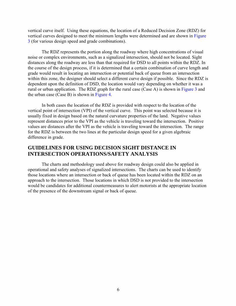
vertical curve itself. Using these equations, the location of a Reduced Decision Zone (RDZ) fovertical curves designed to meet the minimum lengths were determined and are shown in Figure 3 (for various design speed and grade combinations).
r
The RDZ represents the portion along the roadway where high concentrations of visual noise o
is
In both cases the location of the RDZ is provided with respect to the location of the vertical is
GUIDELINES FOR USING DECISION SIGHT DISTANCE IN
The charts and methodology used above for roadway design could also be applied in operati
r complex environments, such as a signalized intersection, should not be located. Sight distances along the roadway are less than that required for DSD to all points within the RDZ. Inthe course of the design process, if it is determined that a certain combination of curve length andgrade would result in locating an intersection or potential back of queue from an intersection within this zone, the designer should select a different curve design if possible. Since the RDZdependent upon the definition of DSD, the location would vary depending on whether it was a rural or urban application. The RDZ graph for the rural case (Case A) is shown in Figure 3 andthe urban case (Case B) is shown in Figure 4.
point of intersection (VPI) of the vertical curve. This point was selected because it usually fixed in design based on the natural curvature properties of the land. Negative values represent distances prior to the VPI as the vehicle is traveling toward the intersection. Positivevalues are distances after the VPI as the vehicle is traveling toward the intersection. The range for the RDZ is between the two lines at the particular design speed for a given algebraic difference in grade.
INTERSECTION OPERATIONS/SAFETY ANALYSIS
onal and safety analyses of signalized intersections. The charts can be used to identifythose locations where an intersection or back of queue has been located within the RDZ on an approach to the intersection. Those locations in which DSD is not provided to the intersection would be candidates for additional countermeasures to alert motorists at the appropriate locationof the presence of the downstream signal or back of queue.
6
Figure 3. Reduced Decision Zone Location for Rural Roadway Applications.
7
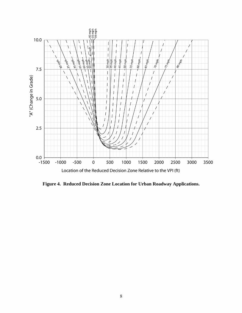
Figure 4. Reduced Decision Zone Location for Urban Roadway Applications.
8
REFERENCES
1. A Policy on Geometric Design of Highways and Streets. American Association of State Highway Transportation Officials, Washington, D.C., 2000.
2. Texas Roadway Design Manual. Texas Department of Transportation, Austin, Texas,
April 2004 (Revised). http://manuals.dot.state.tx.us/dynaweb/coldesig/rdw
9
