enms 10.5 ip service manager
TRANSCRIPT
Standard
Part No. 321540-B12-February-2007
4655 Great America ParkwaySanta Clara, CA 95054
Enterprise Network Management System 10.5
IP Service Manager
2
321540-B
Copyright © 1999–2007 Nortel NetworksAll rights reserved.The information in this document is subject to change without notice. The statements, configurations, technical data, and recommendations in this document are believed to be accurate and reliable, but are presented without express or implied warranty. Users must take full responsibility for their applications of any products specified in this document. The information in this document is proprietary to Nortel Networks Inc.
The software described in this document is furnished under a license agreement and may be used only in accordance with the terms of that license. The software license agreement is included in this document.
Trademarks
Nortel Networks, the Nortel logo, the Globemark, Accelar, Bay Networks, BayStack, Centillion, Meridian, Optivity, Passport, Unified Networks, and Versalar are trademarks of Nortel Networks.
Adobe and Acrobat Reader are trademarks of Adobe Systems Incorporated.
HyperHelp is a trademark of Bristol Technology.
Cisco and Cisco Systems are trademarks of Cisco Systems, Incorporated.
HP-UX and OpenView are trademarks of Hewlett-Packard Corporation.
Oracle is a trademark of Oracle Corporation.
IBM, NetView, RS/6000, Tivoli, TME, and TME 10 are trademarks of IBM Corporation.
Intel and Pentium are registered trademarks of Intel Corporation.
Microsoft, Win32, Windows, Windows 2003, and Windows XP are registered trademarks of Microsoft Corporation.
Netscape Navigator is a trademark of Netscape Communications Corporation.
UNIX is a registered trademark of X/Open Company Limited.
SPARC and SPARCstation are trademarks of Sparc International, Inc.
Sun, Solaris, and Java are trademarks or registered trademarks of Sun Microsystems, Incorporated.
Mozilla and Firefox are trademarks of the Mozilla Foundation.
All other trademarks are the property of their respective owners.
Restricted rights legendUse, duplication, or disclosure by the United States Government is subject to restrictions as set forth in subparagraph (c)(1)(ii) of the Rights in Technical Data and Computer Software clause at DFARS 252.227-7013.Notwithstanding any other license agreement that may pertain to, or accompany the delivery of, this computer software, the rights of the United States Government regarding its use, reproduction, and disclosure are as set forth in the Commercial Computer Software-Restricted Rights clause at FAR 52.227-19.
3
IP Service Manager
Statement of conditionsIn the interest of improving internal design, operational function, and/or reliability, Nortel Networks Inc. reserves the right to make changes to the products described in this document without notice.Nortel Networks Inc. does not assume any liability that may occur due to the use or application of the product(s) or circuit layout(s) described herein.Portions of the code in this software product may be Copyright © 1988, Regents of the University of California. All rights reserved. Redistribution and use in source and binary forms of such portions are permitted, provided that the above copyright notice and this paragraph are duplicated in all such forms and that any documentation, advertising materials, and other materials related to such distribution and use acknowledge that such portions of the software were developed by the University of California, Berkeley. The name of the University may not be used to endorse or promote products derived from such portions of the software without specific prior written permission.SUCH PORTIONS OF THE SOFTWARE ARE PROVIDED “AS IS” AND WITHOUT ANY EXPRESS OR IMPLIED WARRANTIES, INCLUDING, WITHOUT LIMITATION, THE IMPLIED WARRANTIES OF MERCHANTABILITY AND FITNESS FOR A PARTICULAR PURPOSE.In addition, the program and information contained herein are licensed only pursuant to a license agreement that contains restrictions on use and disclosure (that may incorporate by reference certain limitations and notices imposed by third parties).
Nortel Networks Inc. Enterprise network management software license agreement
NOTICE: Please carefully read this license agreement before copying or using the accompanying Enterprise network management software or installing the hardware unit with pre-enabled Enterprise network management software (each of which is referred to as “Software” in this Agreement). BY COPYING OR USING THE SOFTWARE, YOU ACCEPT ALL OF THE TERMS AND CONDITIONS OF THIS LICENSE AGREEMENT. THE TERMS EXPRESSED IN THIS AGREEMENT ARE THE ONLY TERMS UNDER WHICH NORTEL NETWORKS WILL PERMIT YOU TO USE THE SOFTWARE. If you do not accept these terms and conditions, return the product, unused and in the original shipping container, within 30 days of purchase to obtain a credit for the full purchase price.
1. License grant. Nortel Networks Inc. (“Nortel Networks”) grants the end user of the Software (“Licensee”) a personal, nonexclusive license: a) to use the Software either on a single computer or, if applicable, on a single authorized device identified by host ID; b) to copy the Software solely for backup purposes in support of authorized use of the Software; and c) to use and copy the associated user manual solely in support of authorized use of the Software by Licensee. This license applies to the Software only and does not extend to Nortel Networks Agent software or other Nortel Networks software products. Nortel Networks Agent software or other Nortel Networks software products are licensed for use under the terms of the applicable Nortel Networks Inc. Software License Agreement that accompanies such software and upon payment by the end user of the applicable license fees for such software.
2. Restrictions on use; reservation of rights. The Software and user manuals are protected under copyright laws. Nortel Networks and/or its licensors retain all title and ownership in both the Software and user manuals, including any revisions made by Nortel Networks or its licensors. The copyright notice must be reproduced and included with any copy of any portion of the Software or user manuals. Licensee may not modify, translate, decompile, disassemble, use for any competitive analysis, reverse engineer, distribute, or create derivative works from the Software or user manuals or any copy, in whole or in part. Except as expressly provided in this Agreement, Licensee may not copy or transfer the Software or user manuals, in whole or in part. The Software and user manuals embody Nortel Networks’ and its licensors’ confidential and proprietary intellectual property. Licensee shall not disclose to any third party the Software, or any information about the operation, design, performance, or implementation of the Software and user manuals that is confidential to Nortel Networks and its licensors; however, Licensee may grant permission to its consultants, subcontractors, and agents to use the Software at Licensee’s facility, provided they have agreed to use the Software only in accordance with the terms of this license.

4
321540-B
3. Limited warranty. Nortel Networks warrants each item of Software, as delivered by Nortel Networks and properly installed and operated on Nortel Networks hardware or other equipment it is originally licensed for, to function substantially as described in its accompanying user manual during its warranty period, which begins on the date Software is first shipped to Licensee. If any item of Software fails to so function during its warranty period, as the sole remedy Nortel Networks will at its discretion provide a suitable fix, patch, or workaround for the problem that may be included in a future Software release. Nortel Networks further warrants to Licensee that the media on which the Software is provided will be free from defects in materials and workmanship under normal use for a period of 90 days from the date the Software is first shipped to Licensee. Nortel Networks will replace defective media at no charge if it is returned to Nortel Networks during the warranty period along with proof of the date of shipment. This warranty does not apply if the media has been damaged as a result of accident, misuse, or abuse. The Licensee assumes all responsibility for selection of the Software to achieve Licensee’s intended results and for the installation, use, and results obtained from the Software. Nortel Networks does not warrant a) that the functions contained in the software will meet the Licensee’s requirements, b) that the Software will operate in the hardware or software combinations that the Licensee may select, c) that the operation of the Software will be uninterrupted or error free, or d) that all defects in the operation of the Software will be corrected. Nortel Networks is not obligated to remedy any Software defect that cannot be reproduced with the latest Software release. These warranties do not apply to the Software if it has been (i) altered, except by Nortel Networks or in accordance with its instructions; (ii) used in conjunction with another vendor’s product, resulting in the defect; or (iii) damaged by improper environment, abuse, misuse, accident, or negligence. THE FOREGOING WARRANTIES AND LIMITATIONS ARE EXCLUSIVE REMEDIES AND ARE IN LIEU OF ALL OTHER WARRANTIES EXPRESS OR IMPLIED, INCLUDING WITHOUT LIMITATION ANY WARRANTY OF MERCHANTABILITY OR FITNESS FOR A PARTICULAR PURPOSE. Licensee is responsible for the security of its own data and information and for maintaining adequate procedures apart from the Software to reconstruct lost or altered files, data, or programs.
4. Limitation of liability. IN NO EVENT WILL NORTEL NETWORKS OR ITS LICENSORS BE LIABLE FOR ANY COST OF SUBSTITUTE PROCUREMENT; SPECIAL, INDIRECT, INCIDENTAL, OR CONSEQUENTIAL DAMAGES; OR ANY DAMAGES RESULTING FROM INACCURATE OR LOST DATA OR LOSS OF USE OR PROFITS ARISING OUT OF OR IN CONNECTION WITH THE PERFORMANCE OF THE SOFTWARE, EVEN IF NORTEL NETWORKS HAS BEEN ADVISED OF THE POSSIBILITY OF SUCH DAMAGES. IN NO EVENT SHALL THE LIABILITY OF NORTEL NETWORKS RELATING TO THE SOFTWARE OR THIS AGREEMENT EXCEED THE PRICE PAID TO NORTEL NETWORKS FOR THE SOFTWARE LICENSE.
5. Government licensees. This provision applies to all Software and documentation acquired directly or indirectly by or on behalf of the United States Government. The Software and documentation are commercial products, licensed on the open market at market prices, and were developed entirely at private expense and without the use of any U.S. Government funds. The license to the U.S. Government is granted only with restricted rights, and use, duplication, or disclosure by the U.S. Government is subject to the restrictions set forth in subparagraph (c)(1) of the Commercial Computer Software––Restricted Rights clause of FAR 52.227-19 and the limitations set out in this license for civilian agencies, and subparagraph (c)(1)(ii) of the Rights in Technical Data and Computer Software clause of DFARS 252.227-7013, for agencies of the Department of Defense or their successors, whichever is applicable.
6. Use of software in the European Community. This provision applies to all Software acquired for use within the European Community. If Licensee uses the Software within a country in the European Community, the Software Directive enacted by the Council of European Communities Directive dated 14 May, 1991, will apply to the examination of the Software to facilitate interoperability. Licensee agrees to notify Nortel Networks of any such intended examination of the Software and may procure support and assistance from Nortel Networks.
7. Term and termination. This license is effective until terminated; however, all of the restrictions with respect to Nortel Networks’ copyright in the Software and user manuals will cease being effective at the date of expiration of the Nortel Networks copyright; those restrictions relating to use and disclosure of Nortel Networks’ confidential information shall continue in effect. Licensee may terminate this license at any time. The license will automatically terminate if Licensee fails to comply with any of the terms and conditions of the license. Upon termination for any reason, Licensee will immediately destroy or return to Nortel Networks the Software, user manuals, and all copies. Nortel Networks is not liable to Licensee for damages in any form solely by reason of the termination of this license.
5
IP Service Manager
8. Export and re-export. Licensee agrees not to export, directly or indirectly, the Software or related technical data or information without first obtaining any required export licenses or other governmental approvals. Without limiting the foregoing, Licensee, on behalf of itself and its subsidiaries and affiliates, agrees that it will not, without first obtaining all export licenses and approvals required by the U.S. Government: (i) export, re-export, transfer, or divert any such Software or technical data, or any direct product thereof, to any country to which such exports or re-exports are restricted or embargoed under United States export control laws and regulations, or to any national or resident of such restricted or embargoed countries; or (ii) provide the Software or related technical data or information to any military end user or for any military end use, including the design, development, or production of any chemical, nuclear, or biological weapons.
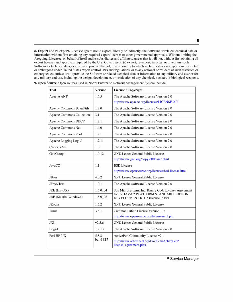
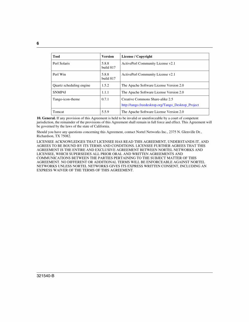
9. Open Source. Open sources used in Nortel Enterprise Network Management System include:
Tool Version License / Copyright
Apache ANT 1.6.5 The Apache Software License Version 2.0
http://www.apache.org/licenses/LICENSE-2.0
Apache Commons BeanUtils 1.7.0 The Apache Software License Version 2.0
Apache Commons Collections 3.1 The Apache Software License Version 2.0
Apache Commons DBCP 1.2.1 The Apache Software License Version 2.0
Apache Commons Net 1.4.0 The Apache Software License Version 2.0
Apache Commons Pool 1.2 The Apache Software License Version 2.0
Apache Logging Log4J 1.2.11 The Apache Software License Version 2.0
Castor XML 1.0 The Apache Software License Version 2.0
GnuGetopt 1.0.12 GNU Lesser General Public License
http://www.gnu.org/copyleft/lesser.html
JavaCC 1.1 BSD License
http://www.opensource.org/licenses/bsd-license.html
JBoss 4.0.2 GNU Lesser General Public License
JFreeChart 1.0.1 The Apache Software License Version 2.0
JRE (HP-UX) 1.5.0_04 Sun Microsystems, Inc. Binary Code License Agreement for the JAVA 2 PLATFORM STANDARD EDITION DEVELOPMENT KIT 5 (license in kit)JRE (Solaris, Windows) 1.5.0_08
JRobin 1.5.2 GNU Lesser General Public License
JUnit 3.8.1 Common Public License Version 1.0
http://www.opensource.org/licenses/cpl.php
JXL v2.5.6 GNU Lesser General Public License
Log4J 1.2.13 The Apache Software License Version 2.0
Perl HP-UX 5.8.8 build 817
ActivePerl Community License v2.1
http://www.activeperl.org/Products/ActivePerl/license_agreement.plex
6
321540-B
10. General. If any provision of this Agreement is held to be invalid or unenforceable by a court of competent jurisdiction, the remainder of the provisions of this Agreement shall remain in full force and effect. This Agreement will be governed by the laws of the state of California.
Should you have any questions concerning this Agreement, contact Nortel Networks Inc., 2375 N. Glenville Dr., Richardson, TX 75082.
LICENSEE ACKNOWLEDGES THAT LICENSEE HAS READ THIS AGREEMENT, UNDERSTANDS IT, AND AGREES TO BE BOUND BY ITS TERMS AND CONDITIONS. LICENSEE FURTHER AGREES THAT THIS AGREEMENT IS THE ENTIRE AND EXCLUSIVE AGREEMENT BETWEEN NORTEL NETWORKS AND LICENSEE, WHICH SUPERSEDES ALL PRIOR ORAL AND WRITTEN AGREEMENTS AND COMMUNICATIONS BETWEEN THE PARTIES PERTAINING TO THE SUBJECT MATTER OF THIS AGREEMENT. NO DIFFERENT OR ADDITIONAL TERMS WILL BE ENFORCEABLE AGAINST NORTEL NETWORKS UNLESS NORTEL NETWORKS GIVES ITS EXPRESS WRITTEN CONSENT, INCLUDING AN EXPRESS WAIVER OF THE TERMS OF THIS AGREEMENT.
Perl Solaris 5.8.8 build 817
ActivePerl Community License v2.1
Perl Win 5.8.8 build 817
ActivePerl Community License v2.1
Quartz scheduling engine 1.5.2 The Apache Software License Version 2.0
SNMP4J 1.1.1 The Apache Software License Version 2.0
Tango-icon-theme 0.7.1 Creative Commons Share-alike 2.5
http://tango.freedesktop.org/Tango_Desktop_Project
Tomcat 5.5.9 The Apache Software License Version 2.0
Tool Version License / Copyright
7
IP Service Manager
Contents
Enterprise Network Management System 10.5 . . . . . . . . . . . . . . . . . . . . . . . . . 1
Chapter 1Getting Started . . . . . . . . . . . . . . . . . . . . . . . . . . . . . . . . . . . . . . . . . . . . . . . . . 9About this guide . . . . . . . . . . . . . . . . . . . . . . . . . . . . . . . . . . . . . . . . . . . . . . . . . . . . . . . 9Audience . . . . . . . . . . . . . . . . . . . . . . . . . . . . . . . . . . . . . . . . . . . . . . . . . . . . . . . . . . . 10Acronyms . . . . . . . . . . . . . . . . . . . . . . . . . . . . . . . . . . . . . . . . . . . . . . . . . . . . . . . . . . . 11Symbols and text conventions . . . . . . . . . . . . . . . . . . . . . . . . . . . . . . . . . . . . . . . . . . . 12Related publications . . . . . . . . . . . . . . . . . . . . . . . . . . . . . . . . . . . . . . . . . . . . . . . . . . . 14How to get Help . . . . . . . . . . . . . . . . . . . . . . . . . . . . . . . . . . . . . . . . . . . . . . . . . . . . . . 14
Getting Help from the Nortel Web site . . . . . . . . . . . . . . . . . . . . . . . . . . . . . . 14Getting Help over the phone from a Nortel Solutions Center . . . . . . . . . . . . . 15Getting Help from a specialist by using an Express Routing Code . . . . . . . . . 15Getting Help through a Nortel distributor or reseller . . . . . . . . . . . . . . . . . . . . 15
Feedback . . . . . . . . . . . . . . . . . . . . . . . . . . . . . . . . . . . . . . . . . . . . . . . . . . . . . . . . . . . 16
Chapter 2Launching IP Service Manager. . . . . . . . . . . . . . . . . . . . . . . . . . . . . . . . . . . 17Access Control for IP Service Manager . . . . . . . . . . . . . . . . . . . . . . . . . . . . . . . . . . . . 17Starting IP Service Manager . . . . . . . . . . . . . . . . . . . . . . . . . . . . . . . . . . . . . . . . . . . . 18IP Service Manager window . . . . . . . . . . . . . . . . . . . . . . . . . . . . . . . . . . . . . . . . . . . . . 19Setting Preferences . . . . . . . . . . . . . . . . . . . . . . . . . . . . . . . . . . . . . . . . . . . . . . . . . . . 28
Chapter 3Discovering IP telephony end points. . . . . . . . . . . . . . . . . . . . . . . . . . . . . . 31Configure window . . . . . . . . . . . . . . . . . . . . . . . . . . . . . . . . . . . . . . . . . . . . . . . . . . . . . 31
Configure panel . . . . . . . . . . . . . . . . . . . . . . . . . . . . . . . . . . . . . . . . . . . . . . . . . . . 32Status & History panel . . . . . . . . . . . . . . . . . . . . . . . . . . . . . . . . . . . . . . . . . . . . . . 34
Adding VoIP systems to the VoIP system list . . . . . . . . . . . . . . . . . . . . . . . . . . . . . . . 35Discovering the end points . . . . . . . . . . . . . . . . . . . . . . . . . . . . . . . . . . . . . . . . . . . . . . 37
8 Contents
321540-B
Reviewing a discovery process . . . . . . . . . . . . . . . . . . . . . . . . . . . . . . . . . . . . . . . . . . 38Scheduling rediscovery with Auto Rediscovery . . . . . . . . . . . . . . . . . . . . . . . . . . . . . . 40Modifying VoIP system information . . . . . . . . . . . . . . . . . . . . . . . . . . . . . . . . . . . . . . . 41Deleting VoIP systems from the VoIP system list . . . . . . . . . . . . . . . . . . . . . . . . . . . . 42Saving the VoIP system list . . . . . . . . . . . . . . . . . . . . . . . . . . . . . . . . . . . . . . . . . . . . . 42
Chapter 4Displaying the network and devices . . . . . . . . . . . . . . . . . . . . . . . . . . . . . . 45Displaying the service view or VoIP system . . . . . . . . . . . . . . . . . . . . . . . . . . . . . . . . . 45Displaying the converged view or connectivity . . . . . . . . . . . . . . . . . . . . . . . . . . . . . . . 46Displaying all IP phones for a VoIP system . . . . . . . . . . . . . . . . . . . . . . . . . . . . . . . . . 47Displaying the properties of an object . . . . . . . . . . . . . . . . . . . . . . . . . . . . . . . . . . . . . 48Creating a new object . . . . . . . . . . . . . . . . . . . . . . . . . . . . . . . . . . . . . . . . . . . . . . . . . 49Refreshing a view . . . . . . . . . . . . . . . . . . . . . . . . . . . . . . . . . . . . . . . . . . . . . . . . . . . . . 50
Chapter 5Managing filters . . . . . . . . . . . . . . . . . . . . . . . . . . . . . . . . . . . . . . . . . . . . . . . 51Filter Editor window . . . . . . . . . . . . . . . . . . . . . . . . . . . . . . . . . . . . . . . . . . . . . . . . . . . 52Filter Definition window . . . . . . . . . . . . . . . . . . . . . . . . . . . . . . . . . . . . . . . . . . . . . . . . 54Creating, modifying, and deleting filters . . . . . . . . . . . . . . . . . . . . . . . . . . . . . . . . . . . . 55Running a filter . . . . . . . . . . . . . . . . . . . . . . . . . . . . . . . . . . . . . . . . . . . . . . . . . . . . . . . 57Importing and exporting filters and filter data . . . . . . . . . . . . . . . . . . . . . . . . . . . . . . . . 58
Chapter 6Troubleshooting the IP telephony network . . . . . . . . . . . . . . . . . . . . . . . . . 63Monitoring the network for faults . . . . . . . . . . . . . . . . . . . . . . . . . . . . . . . . . . . . . . . . . 65Identifying a fault . . . . . . . . . . . . . . . . . . . . . . . . . . . . . . . . . . . . . . . . . . . . . . . . . . . . . 66Investigating a fault on an IP telephony end point . . . . . . . . . . . . . . . . . . . . . . . . . . . . 68General investigations . . . . . . . . . . . . . . . . . . . . . . . . . . . . . . . . . . . . . . . . . . . . . . . . . 70Performance statistics and definitions . . . . . . . . . . . . . . . . . . . . . . . . . . . . . . . . . . . . . 75
Index . . . . . . . . . . . . . . . . . . . . . . . . . . . . . . . . . . . . . . . . . . . . . . . . . . . . . . . . 77
9
IP Service Manager
Chapter 1Getting Started
Topics covered in this chapter are:
• “About this guide” on page 9
• “Audience” on page 10
• “Acronyms” on page 11
• “Symbols and text conventions” on page 12
• “Related publications” on page 14
• “How to get Help” on page 14
• “Feedback” on page 16
About this guide
The IP Service Manager is an advanced IP management module that network administrators use to manage and troubleshoot IP telephony networks. IP Service Manager operates within the framework of Nortel Enterprise Network Management System (NMS) 10.5 to provide integrated discovery, visualization, and troubleshooting of Nortel IP Telephony end points that are registered with a Voice over IP (VoIP) system. Fault conditions, performance statistics, and call quality can all be accessed easily through the IP Service Manager graphical user interface.
10 Chapter 1 Getting Started
321540-B
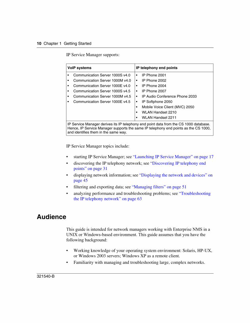
IP Service Manager supports:
IP Service Manager topics include:
• starting IP Service Manager; see “Launching IP Service Manager” on page 17
• discovering the IP telephony network; see “Discovering IP telephony end points” on page 31
• displaying network information; see “Displaying the network and devices” on page 45
• filtering and exporting data; see “Managing filters” on page 51
• analyzing performance and troubleshooting problems; see “Troubleshooting the IP telephony network” on page 63
Audience
This guide is intended for network managers working with Enterprise NMS in a UNIX or Windows-based environment. This guide assumes that you have the following background:
• Working knowledge of your operating system environment: Solaris, HP-UX, or Windows 2003 servers; Windows XP as a remote client.
• Familiarity with managing and troubleshooting large, complex networks.
VoIP systems IP telephony end points
• Communication Server 1000S v4.0• Communication Server 1000M v4.0• Communication Server 1000E v4.0• Communication Server 1000S v4.5• Communication Server 1000M v4.5• Communication Server 1000E v4.5
• IP Phone 2001• IP Phone 2002• IP Phone 2004• IP Phone 2007• IP Audio Conference Phone 2033• IP Softphone 2050• Mobile Voice Client (MVC) 2050• WLAN Handset 2210• WLAN Handset 2211
IP Service Manager derives its IP telephony end point data from the CS 1000 database. Hence, IP Service Manager supports the same IP telephony end points as the CS 1000, and identifies them in the same way.
Chapter 1 Getting Started 11
IP Service Manager
• Experience with working with Nortel and standards-based networking devices.
• Working knowledge of the transmission and management protocols used on your network.
• If Enterprise NMS is installed with HP OpenView Network Node Manager or IBM/Tivoli Netview umbrella management platforms, familiarity with the deployed platform.
Acronyms
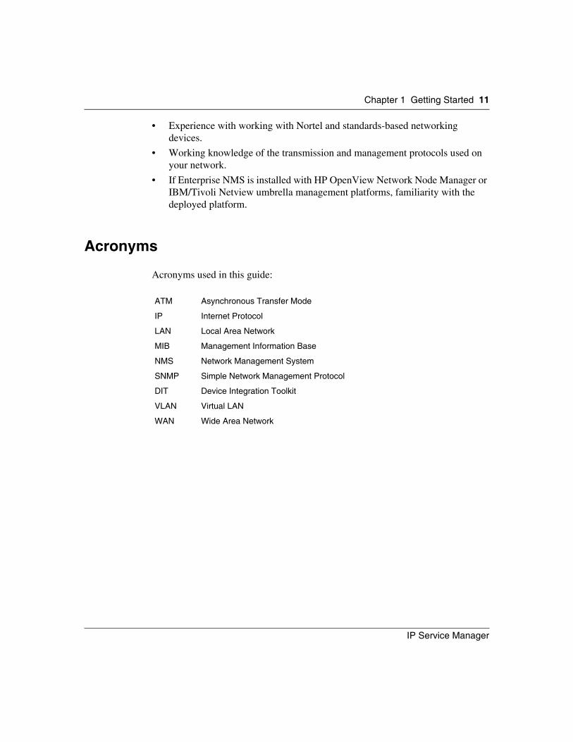
Acronyms used in this guide:
ATM Asynchronous Transfer Mode
IP Internet Protocol
LAN Local Area Network
MIB Management Information Base
NMS Network Management System
SNMP Simple Network Management Protocol
DIT Device Integration Toolkit
VLAN Virtual LAN
WAN Wide Area Network
12 Chapter 1 Getting Started
321540-B
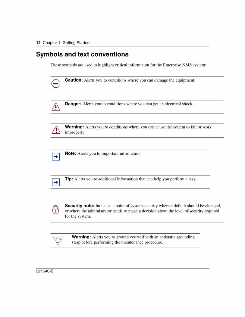
Symbols and text conventionsThese symbols are used to highlight critical information for the Enterprise NMS system:
Caution: Alerts you to conditions where you can damage the equipment.
Danger: Alerts you to conditions where you can get an electrical shock.
Warning: Alerts you to conditions where you can cause the system to fail or work improperly.
Note: Alerts you to important information.
Tip: Alerts you to additional information that can help you perform a task.
!Security note: Indicates a point of system security where a default should be changed, or where the administrator needs to make a decision about the level of security required for the system.
Warning: Alerts you to ground yourself with an antistatic grounding strap before performing the maintenance procedure.
Chapter 1 Getting Started 13
IP Service Manager
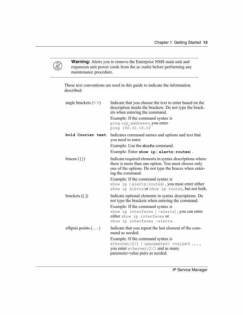
These text conventions are used in this guide to indicate the information described:
Warning: Alerts you to remove the Enterprise NMS main unit and expansion unit power cords from the ac outlet before performing any maintenance procedure.
angle brackets (< >) Indicate that you choose the text to enter based on the description inside the brackets. Do not type the brack-ets when entering the command.Example: If the command syntax isping <ip_address>, you enterping 192.32.10.12
bold Courier text Indicates command names and options and text that you need to enter.Example: Use the dinfo command. Example: Enter show ip {alerts|routes}.
braces ({}) Indicate required elements in syntax descriptions where there is more than one option. You must choose only one of the options. Do not type the braces when enter-ing the command.Example: If the command syntax isshow ip {alerts|routes}, you must enter eithershow ip alerts or show ip routes, but not both.
brackets ([ ]) Indicate optional elements in syntax descriptions. Do not type the brackets when entering the command.Example: If the command syntax isshow ip interfaces [-alerts], you can entereither show ip interfaces or show ip interfaces -alerts.
ellipsis points (. . . ) Indicate that you repeat the last element of the com-mand as needed.Example: If the command syntax isethernet/2/1 [<parameter> <value>]... ,you enter ethernet/2/1 and as manyparameter-value pairs as needed.
14 Chapter 1 Getting Started
321540-B
Related publications
For an overview of Enterprise NMS documentation, refer to the Introduction guide (part number 321538-B). The Network Discovery and InfoCenter guide (part number 207569-H) is referred to specifically in this guide.
How to get Help
This section explains how to get help for Nortel products and services.
Getting Help from the Nortel Web site
The best way to get technical support for Nortel products is from the Nortel Technical Support Web site:
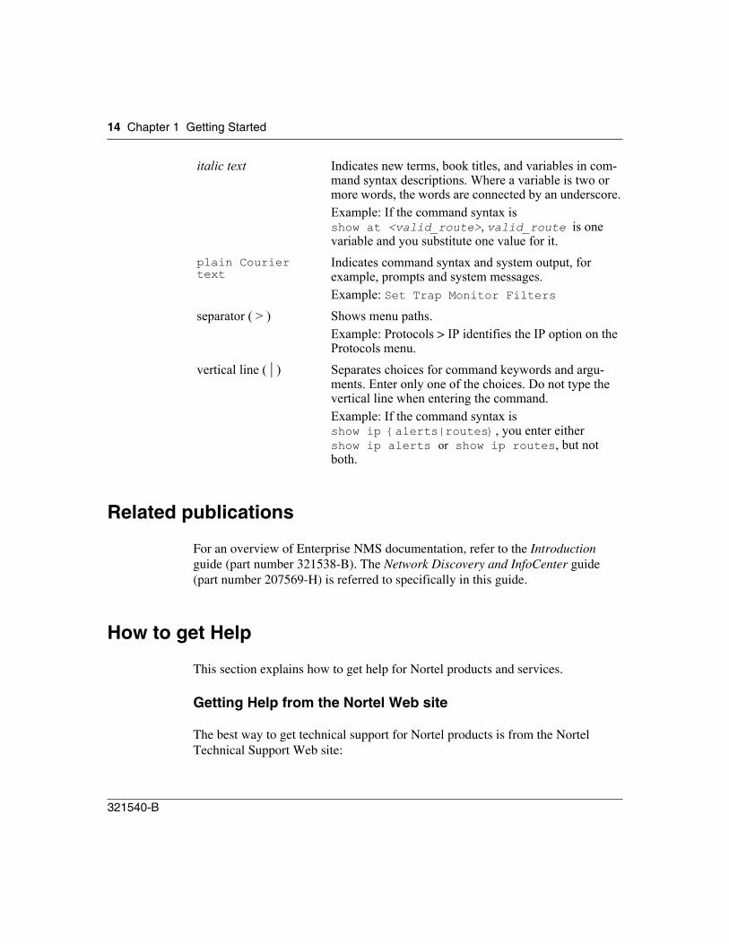
italic text Indicates new terms, book titles, and variables in com-mand syntax descriptions. Where a variable is two or more words, the words are connected by an underscore.Example: If the command syntax isshow at <valid_route>, valid_route is onevariable and you substitute one value for it.
plain Courier text
Indicates command syntax and system output, for example, prompts and system messages.Example: Set Trap Monitor Filters
separator ( > ) Shows menu paths. Example: Protocols > IP identifies the IP option on the Protocols menu.
vertical line ( | ) Separates choices for command keywords and argu-ments. Enter only one of the choices. Do not type the vertical line when entering the command.Example: If the command syntax isshow ip {alerts|routes}, you enter eithershow ip alerts or show ip routes, but notboth.
Chapter 1 Getting Started 15
IP Service Manager
http://www.nortel.com/support
This site provides quick access to software, documentation, bulletins, and tools to address issues with Nortel products. More specifically, the site enables you to:
• download software, documentation, and product bulletins
• search the Technical Support Web site and the Nortel Knowledge Base for answers to technical issues
• sign up for automatic notification of new software and documentation for Nortel equipment
• open and manage technical support cases
Getting Help over the phone from a Nortel Solutions Center
If you don’t find the information you require on the Nortel Technical Support Web site, and have a Nortel support contract, you can also get help over the phone from a Nortel Solutions Center.
In North America, call 1-800-4NORTEL (1-800-466-7835).
Outside North America, go to the following Web site to obtain the phone number for your region:
http://www.nortel.com/callus
Getting Help from a specialist by using an Express Routing Code
To access some Nortel Technical Solutions Centers, you can use an Express Routing Code (ERC) to quickly route your call to a specialist in your Nortel product or service. To locate the ERC for your product or service, go to:
http://www.nortel.com/erc
Getting Help through a Nortel distributor or reseller
If you purchased a service contract for your Nortel product from a distributor or authorized reseller, contact the technical support staff for that distributor or reseller.
16 Chapter 1 Getting Started
321540-B
Feedback
We would like to hear from you if you have any comments, questions, or concerns about this or other items of Enterprise NMS documentation. Please email us at [email protected] with any feedback you would like to offer.
There are also email links at the bottom of every Help topic. Just click the link to send us feedback about that Help topic.
11
Device Configuration
Chapter 2Launching IP Service Manager
Launching IP Service Manager involves:
• having the required permission token; see “Access Control for IP Service Manager” on page 11
• “Starting IP Service Manager” on page 12
• familiarizing yourself with the IP Service Manager interface; see “IP Service Manager window” on page 13
• setting your preferences; see “Setting Preferences” on page 22
Access Control for IP Service Manager
To use IP Service Manager, your Enterprise NMS user name must have the IP Service Manager permission token, IPSM_ACCESS, attached with either read/write or read-only permission.
An authorized administrator assigns permission tokens through Access Control Administration. For more information about using Access Control Administration, see the Security guide (part number 321536-B) or, from within the Help system, click Access Control Administration online Help.
With read/write access permission, you have full access to all IP Service Manager functions.
12 Chapter 2 Launching IP Service Manager
321540-B
With read-only access permission, you can run predefined filters, monitor the network, launch troubleshooting tools, and manage faults. You cannot run a discovery, create new filters, or create new objects.
Starting IP Service Manager
You can start IP Service Manager from within InfoCenter, by workstation command, or through a web browser.
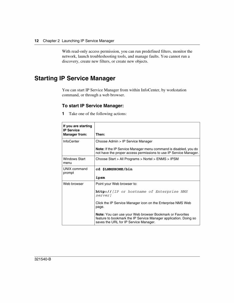
To start IP Service Manager:
1 Take one of the following actions:
If you are starting IP Service Manager from: Then:
InfoCenter Choose Admin > IP Service Manager
Note: If the IP Service Manager menu command is disabled, you do not have the proper access permissions to use IP Service Manager.
Windows Start menu
Choose Start > All Programs > Nortel > ENMS > IPSM
UNIX command prompt
cd $LNMSHOME/bin
ipsm
Web browser Point your Web browser to:
http://[IP or hostname of Enterprise NMS server]
Click the IP Service Manager icon on the Enterprise NMS Web page.
Note: You can use your Web browser Bookmark or Favorites feature to bookmark the IP Service Manager application. Doing so saves the URL for IP Service Manager.
Chapter 2 Launching IP Service Manager 13
IP Service Manager
2 Enter your Enterprise NMS login information and click Login.The IP Service Manager window opens.
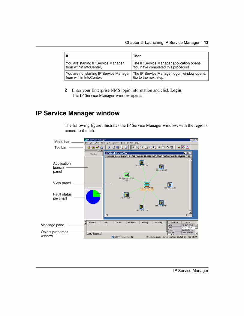
IP Service Manager window
The following figure illustrates the IP Service Manager window, with the regions named to the left.
If Then
You are starting IP Service Manager from within InfoCenter,
The IP Service Manager application opens.You have completed this procedure.
You are not starting IP Service Manager from within InfoCenter,
The IP Service Manager logon window opens.Go to the next step.
Menu bar
Applicationlaunch panel
Toolbar
Fault status pie chart
Message pane
Object properties window
View panel
14 Chapter 2 Launching IP Service Manager
321540-B
Menu bar
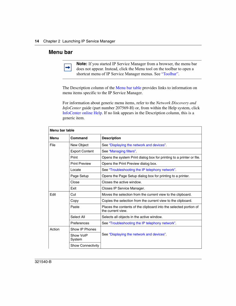
The Description column of the Menu bar table provides links to information on menu items specific to the IP Service Manager.
For information about generic menu items, refer to the Network Discovery and InfoCenter guide (part number 207569-H) or, from within the Help system, click InfoCenter online Help. If no link appears in the Description column, this is a generic item.
Note: If you started IP Service Manager from a browser, the menu bar does not appear. Instead, click the Menu tool on the toolbar to open a shortcut menu of IP Service Manager menus. See “Toolbar”.
Menu bar table
Menu Command Description
File New Object See “Displaying the network and devices”.
Export Content See “Managing filters”.
Print Opens the system Print dialog box for printing to a printer or file.
Print Preview Opens the Print Preview dialog box.
Locate See “Troubleshooting the IP telephony network”.
Page Setup Opens the Page Setup dialog box for printing to a printer.
Close Closes the active window.
Exit Closes IP Service Manager.
Edit Cut Moves the selection from the current view to the clipboard.
Copy Copies the selection from the current view to the clipboard.
Paste Places the contents of the clipboard into the selected portion of the current view.
Select All Selects all objects in the active window.
Preferences See “Troubleshooting the IP telephony network”.
Action Show IP PhonesSee “Displaying the network and devices”.Show VoIP
System
Show Connectivity
Chapter 2 Launching IP Service Manager 15
IP Service Manager
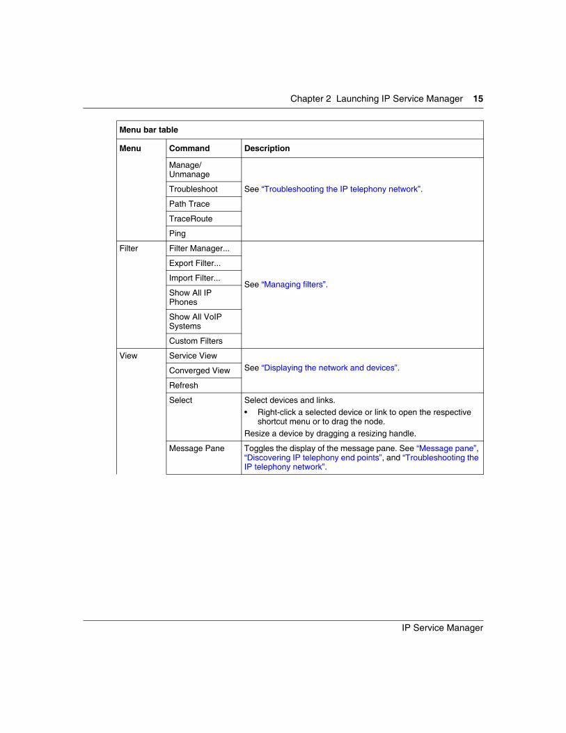
Manage/Unmanage
See “Troubleshooting the IP telephony network”.Troubleshoot
Path Trace
TraceRoute
Ping
Filter Filter Manager...
See “Managing filters”.
Export Filter...
Import Filter...
Show All IP Phones
Show All VoIP Systems
Custom Filters
View Service ViewSee “Displaying the network and devices”.Converged View
Refresh
Select Select devices and links. • Right-click a selected device or link to open the respective
shortcut menu or to drag the node. Resize a device by dragging a resizing handle.
Message Pane Toggles the display of the message pane. See “Message pane”, “Discovering IP telephony end points”, and “Troubleshooting the IP telephony network”.
Menu bar table
Menu Command Description
16 Chapter 2 Launching IP Service Manager
321540-B
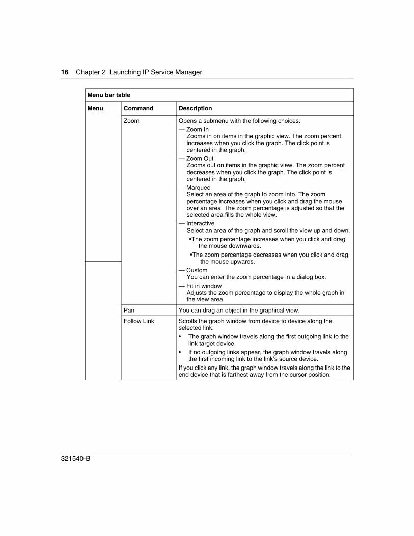
Zoom Opens a submenu with the following choices:— Zoom In
Zooms in on items in the graphic view. The zoom percent increases when you click the graph. The click point is centered in the graph.
— Zoom OutZooms out on items in the graphic view. The zoom percent decreases when you click the graph. The click point is centered in the graph.
— MarqueeSelect an area of the graph to zoom into. The zoom percentage increases when you click and drag the mouse over an area. The zoom percentage is adjusted so that the selected area fills the whole view.
— InteractiveSelect an area of the graph and scroll the view up and down.•The zoom percentage increases when you click and drag
the mouse downwards.•The zoom percentage decreases when you click and drag
the mouse upwards.— Custom
You can enter the zoom percentage in a dialog box.— Fit in window
Adjusts the zoom percentage to display the whole graph in the view area.
Pan You can drag an object in the graphical view.
Follow Link Scrolls the graph window from device to device along the selected link. • The graph window travels along the first outgoing link to the
link target device.• If no outgoing links appear, the graph window travels along
the first incoming link to the link’s source device.If you click any link, the graph window travels along the link to the end device that is farthest away from the cursor position.
Menu bar table
Menu Command Description
Chapter 2 Launching IP Service Manager 17
IP Service Manager
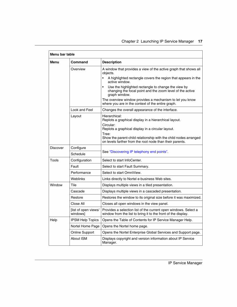
Overview A window that provides a view of the active graph that shows all objects. • A highlighted rectangle covers the region that appears in the
active window. • Use the highlighted rectangle to change the view by
changing the focal point and the zoom level of the active graph window.
The overview window provides a mechanism to let you know where you are in the context of the entire graph.
Look and Feel Changes the overall appearance of the interface.
Layout Hierarchical:Replots a graphical display in a hierarchical layout.Circular:Replots a graphical display in a circular layout.Tree:Show the parent-child relationship with the child nodes arranged on levels farther from the root node than their parents.
Discover ConfigureSee “Discovering IP telephony end points”.
Schedule
Tools Configuration Select to start InfoCenter.
Fault Select to start Fault Summary.
Performance Select to start OmniView.
Weblinks Links directly to Nortel e-business Web sites.
Window Tile Displays multiple views in a tiled presentation.
Cascade Displays multiple views in a cascaded presentation.
Restore Restores the window to its original size before it was maximized.
Close All Closes all open windows in the view panel.
[list of open views/windows]
Provides a selection list of the current open windows. Select a window from the list to bring it to the front of the display.
Help IPSM Help Topics Opens the Table of Contents for IP Service Manager Help.
Nortel Home Page Opens the Nortel home page.
Online Support Opens the Nortel Enterprise Global Services and Support page.
About ISM Displays copyright and version information about IP Service Manager.
Menu bar table
Menu Command Description
18 Chapter 2 Launching IP Service Manager
321540-B
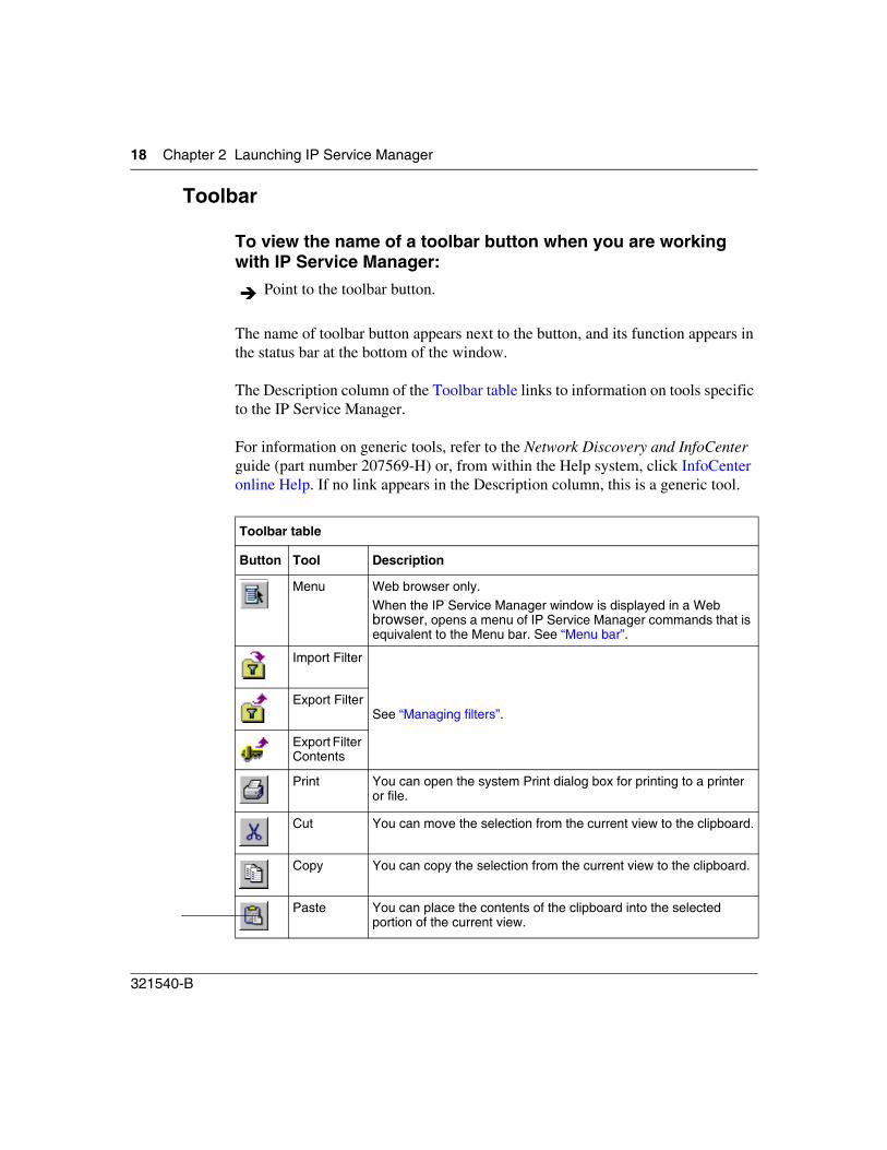
Toolbar
To view the name of a toolbar button when you are working with IP Service Manager:
The name of toolbar button appears next to the button, and its function appears in the status bar at the bottom of the window.
The Description column of the Toolbar table links to information on tools specific to the IP Service Manager.
For information on generic tools, refer to the Network Discovery and InfoCenter guide (part number 207569-H) or, from within the Help system, click InfoCenter online Help. If no link appears in the Description column, this is a generic tool.
Point to the toolbar button.
Toolbar table
Button Tool Description
Menu Web browser only.When the IP Service Manager window is displayed in a Web browser, opens a menu of IP Service Manager commands that is equivalent to the Menu bar. See “Menu bar”.
Import Filter
See “Managing filters”.Export Filter
Export Filter Contents
Print You can open the system Print dialog box for printing to a printer
or file.
Cut You can move the selection from the current view to the clipboard.
Copy You can copy the selection from the current view to the clipboard.
Paste You can place the contents of the clipboard into the selected
portion of the current view.
Chapter 2 Launching IP Service Manager 19
IP Service Manager
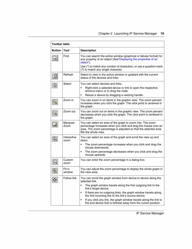
Find You can search the active window (graphical or tabular format) for
any property of an object (See“Displaying the properties of an object”). Use (*) to match any number of characters, or use a question mark (?) to match any single character.
Refresh Select to view in the active window is updated with the current
status of the devices and links.
Select You can select devices and links. • Right-click a selected device or link to open the respective
shortcut menu or to drag the node. • Resize a device by dragging a resizing handle.
Zoom in You can zoom in on items in the graphic view. The zoom percent increases when you click the graph. The click point is centered in the graph.
Zoom out You can zoom out on items in the graphic view. The zoom percent decreases when you click the graph. The click point is centered in the graph.
Marquee Zoom
You can select an area of the graph to zoom into. The zoom percentage increases when you click and drag the mouse over an area. The zoom percentage is adjusted so that the selected area fills the whole view.
Interactive zoom
You can select an area of the graph and scroll the view up and down. • The zoom percentage increases when you click and drag the
mouse downwards.• The zoom percentage decreases when you click and drag the
mouse upwards.
Custom zoom
You can enter the zoom percentage in a dialog box.
Fit in window
You can adjust the zoom percentage to display the whole graph in the view area.
Follow link You can scroll the graph window from device to device along the selected link. • The graph window travels along the first outgoing link to the
link’s target device.• If there are no outgoing links, the graph window travels along
the first incoming link to the link’s source device.• If you click any link, the graph window travels along the link to
the end device that is farthest away from the cursor position.
Toolbar table
Button Tool Description
20 Chapter 2 Launching IP Service Manager
321540-B
Application launch panel
Users start IP Service Manager applications from the application launch panel. In the current release, the Visualization application is available, and IP Service Manager starts this application automatically when IP Service Manager is started.
View panel
The results of most user actions appear in the view panel. Information on specific actions and results is detailed in the context of other, related activities. These activities include:
• “Discovering IP telephony end points”
• “Displaying the network and devices”
• “Managing filters”
• “Troubleshooting the IP telephony network”.
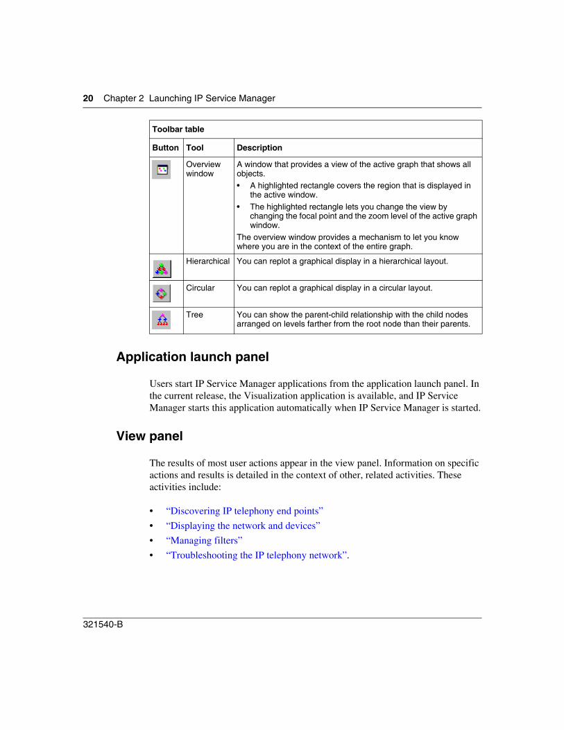
Overview window
A window that provides a view of the active graph that shows all objects. • A highlighted rectangle covers the region that is displayed in
the active window. • The highlighted rectangle lets you change the view by
changing the focal point and the zoom level of the active graph window.
The overview window provides a mechanism to let you know where you are in the context of the entire graph.
Hierarchical You can replot a graphical display in a hierarchical layout.
Circular You can replot a graphical display in a circular layout.
Tree You can show the parent-child relationship with the child nodes arranged on levels farther from the root node than their parents.
Toolbar table
Button Tool Description
Chapter 2 Launching IP Service Manager 21
IP Service Manager
Fault status pie chart
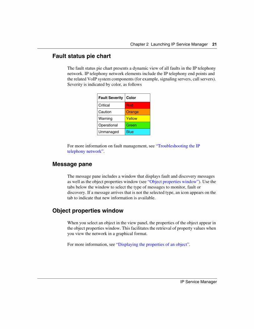
The fault status pie chart presents a dynamic view of all faults in the IP telephony network. IP telephony network elements include the IP telephony end points and the related VoIP system components (for example, signaling servers, call servers). Severity is indicated by color, as follows
For more information on fault management, see “Troubleshooting the IP telephony network”.
Message pane
The message pane includes a window that displays fault and discovery messages as well as the object properties window (see “Object properties window”). Use the tabs below the window to select the type of messages to monitor, fault or discovery. If a message arrives that is not the selected type, an icon appears on the tab to indicate that new information is available.
Object properties window
When you select an object in the view panel, the properties of the object appear in the object properties window. This facilitates the retrieval of property values when you view the network in a graphical format.
For more information, see “Displaying the properties of an object”.
Fault Severity Color
Critical Red
Caution Orange
Warning Yellow
Operational Green
Unmanaged Blue
22 Chapter 2 Launching IP Service Manager
321540-B
Setting Preferences
You can use IP Service Manager to set preferences for a number of applications. The preferences are user-specific so that users can tailor the applications to their requirements.
To set preferences:
1 Do one of the following:
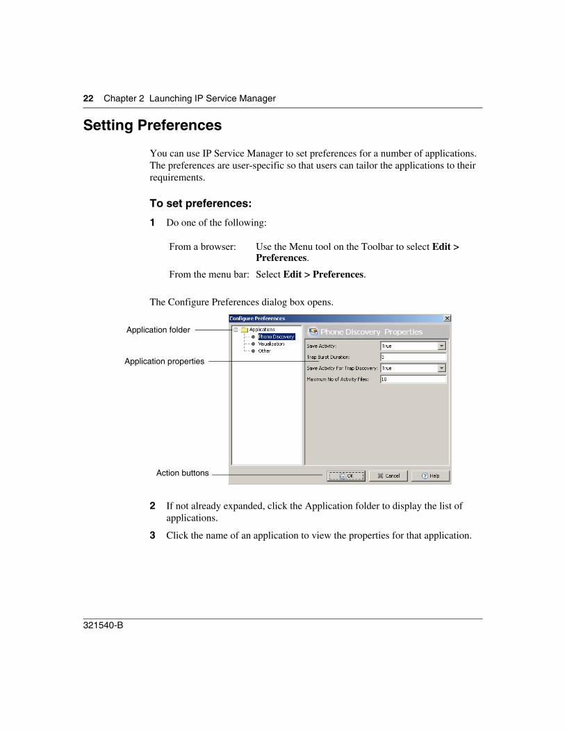
The Configure Preferences dialog box opens.
2 If not already expanded, click the Application folder to display the list of applications.
3 Click the name of an application to view the properties for that application.
From a browser: Use the Menu tool on the Toolbar to select Edit > Preferences.
From the menu bar: Select Edit > Preferences.
Application folder
Application properties
Action buttons
Chapter 2 Launching IP Service Manager 23
IP Service Manager
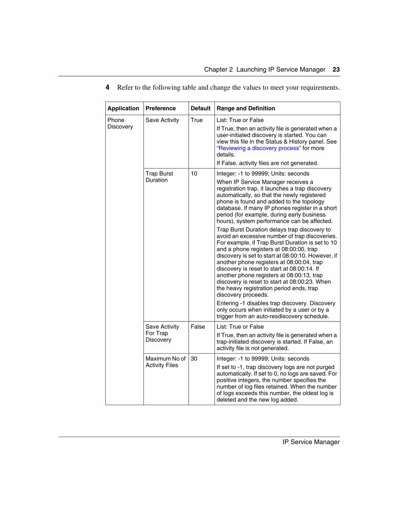
4 Refer to the following table and change the values to meet your requirements.
Application Preference Default Range and Definition
Phone Discovery
Save Activity True List: True or FalseIf True, then an activity file is generated when a user-initiated discovery is started. You can view this file in the Status & History panel. See “Reviewing a discovery process” for more details.If False, activity files are not generated.
Trap Burst Duration
10 Integer: -1 to 99999; Units: secondsWhen IP Service Manager receives a registration trap, it launches a trap discovery automatically, so that the newly registered phone is found and added to the topology database. If many IP phones register in a short period (for example, during early business hours), system performance can be affected.Trap Burst Duration delays trap discovery to avoid an excessive number of trap discoveries. For example, if Trap Burst Duration is set to 10 and a phone registers at 08:00:00, trap discovery is set to start at 08:00:10. However, if another phone registers at 08:00:04, trap discovery is reset to start at 08:00:14. If another phone registers at 08:00:13, trap discovery is reset to start at 08:00:23. When the heavy registration period ends, trap discovery proceeds.Entering -1 disables trap discovery. Discovery only occurs when initiated by a user or by a trigger from an auto-resdiscovery schedule.
Save Activity For Trap Discovery
False List: True or FalseIf True, then an activity file is generated when a trap-initiated discovery is started. If False, an activity file is not generated.
Maximum No of Activity Files
30 Integer: -1 to 99999; Units: secondsIf set to -1, trap discovery logs are not purged automatically. If set to 0, no logs are saved. For positive integers, the number specifies the number of log files retained. When the number of logs exceeds this number, the oldest log is deleted and the new log added.
24 Chapter 2 Launching IP Service Manager
321540-B
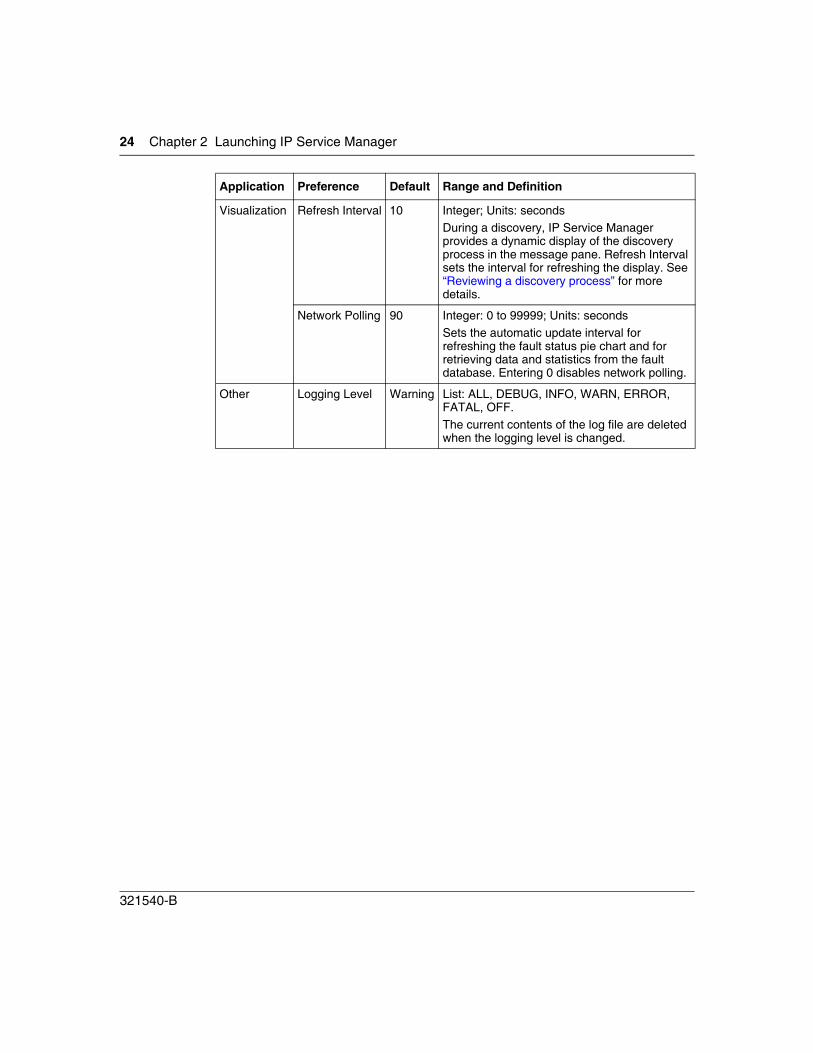
Visualization Refresh Interval 10 Integer; Units: secondsDuring a discovery, IP Service Manager provides a dynamic display of the discovery process in the message pane. Refresh Interval sets the interval for refreshing the display. See “Reviewing a discovery process” for more details.
Network Polling 90 Integer: 0 to 99999; Units: secondsSets the automatic update interval for refreshing the fault status pie chart and for retrieving data and statistics from the fault database. Entering 0 disables network polling.
Other Logging Level Warning List: ALL, DEBUG, INFO, WARN, ERROR, FATAL, OFF.The current contents of the log file are deleted when the logging level is changed.
Application Preference Default Range and Definition
31
IP Service Manager
Chapter 3Discovering IP telephony end points
The IP Service Manager discovers Nortel IP telephony end points registered to a Nortel Communication Server 1000. Discovering the IP telephony end points of your network involves:
• Familiarizing yourself with the Discovery Dialog window; see “Configure window” on page 31
• “Adding VoIP systems to the VoIP system list” on page 35
• “Discovering the end points” on page 37
Other activities associated with discovering IP telephony end points include:
• “Reviewing a discovery process” on page 38
• “Scheduling rediscovery with Auto Rediscovery” on page 40
• “Modifying VoIP system information” on page 41
• “Deleting VoIP systems from the VoIP system list” on page 42
• “Saving the VoIP system list” on page 42
Configure window
Use the Configure window to specify the information required to discover the IP telephony end points, to start a discovery process, and to review the status and results of discovery processes.
32 Chapter 3 Discovering IP telephony end points
321540-B
To open the Configure window:
Do one of the following:
The Configure window opens, and the Configure panel is active.
The Configure window has two panels: Configure and Status & History.
Configure panel
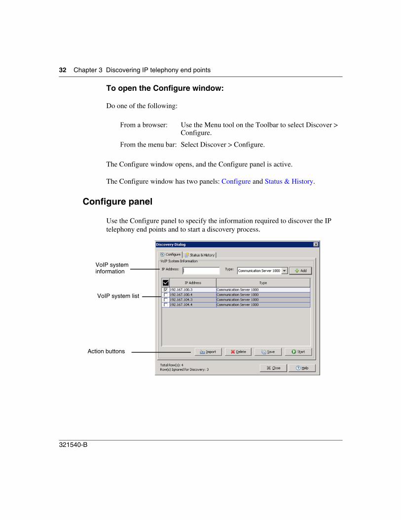
Use the Configure panel to specify the information required to discover the IP telephony end points and to start a discovery process.
From a browser: Use the Menu tool on the Toolbar to select Discover > Configure.
From the menu bar: Select Discover > Configure.
VoIP system information
VoIP system list
Action buttons
Chapter 3 Discovering IP telephony end points 33
IP Service Manager
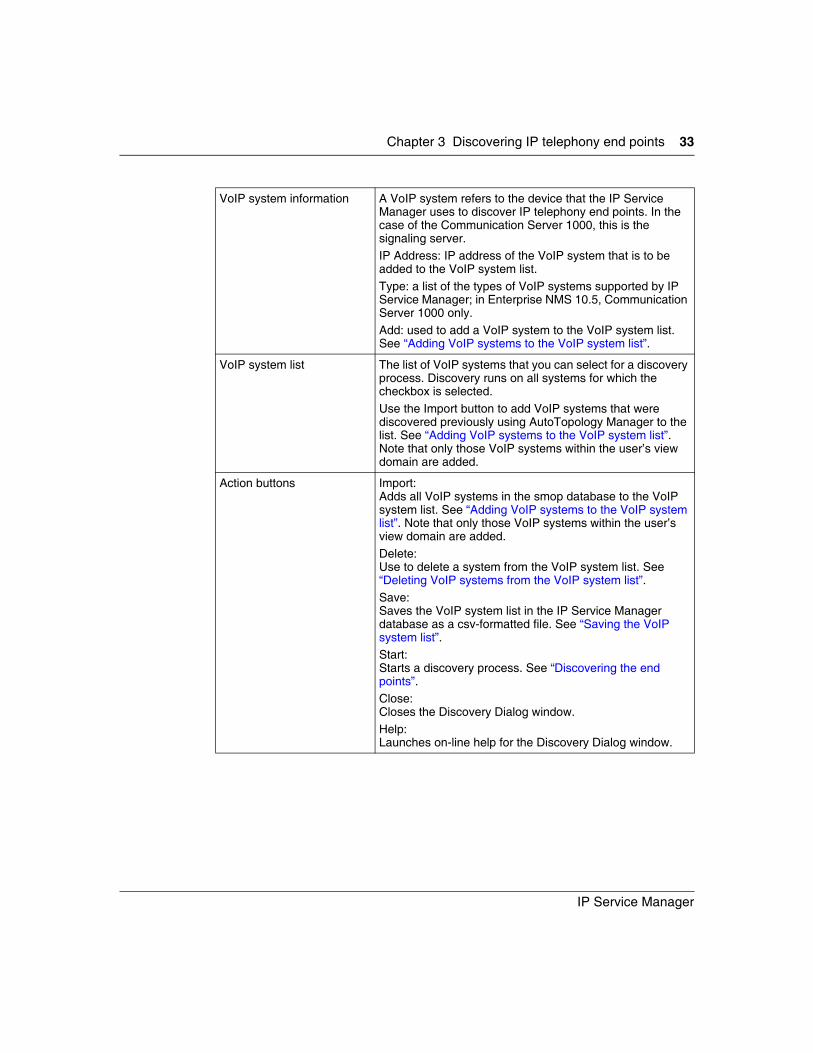
VoIP system information A VoIP system refers to the device that the IP Service Manager uses to discover IP telephony end points. In the case of the Communication Server 1000, this is the signaling server.IP Address: IP address of the VoIP system that is to be added to the VoIP system list.Type: a list of the types of VoIP systems supported by IP Service Manager; in Enterprise NMS 10.5, Communication Server 1000 only.Add: used to add a VoIP system to the VoIP system list. See “Adding VoIP systems to the VoIP system list”.
VoIP system list The list of VoIP systems that you can select for a discovery process. Discovery runs on all systems for which the checkbox is selected.Use the Import button to add VoIP systems that were discovered previously using AutoTopology Manager to the list. See “Adding VoIP systems to the VoIP system list”. Note that only those VoIP systems within the user’s view domain are added.
Action buttons Import: Adds all VoIP systems in the smop database to the VoIP system list. See “Adding VoIP systems to the VoIP system list”. Note that only those VoIP systems within the user’s view domain are added.Delete:Use to delete a system from the VoIP system list. See “Deleting VoIP systems from the VoIP system list”.Save:Saves the VoIP system list in the IP Service Manager database as a csv-formatted file. See “Saving the VoIP system list”.Start:Starts a discovery process. See “Discovering the end points”.Close:Closes the Discovery Dialog window.Help:Launches on-line help for the Discovery Dialog window.

34 Chapter 3 Discovering IP telephony end points
321540-B
Status & History panel
Use the Status & History panel to review the status and results of discovery processes.
Discovery details window Provides a detailed report for the discovery activities selected in the discovery record list. The report updates automatically as discovery proceeds and provides a complete record when discovery is complete.If discovery details are not displayed or updated, press the Refresh button. If that does not resolve the problem, ensure that the Save Activity preference of Phone Discovery is set to True. See “Setting Preferences” for more details.
Action buttons
Discovery activity list
Discovery details window
Chapter 3 Discovering IP telephony end points 35
IP Service Manager
Adding VoIP systems to the VoIP system list
You can manually add systems to the VoIP system list or import systems from the smop database.
To add a VoIP system to the VoIP system list manually:
1 Do one of the following:
The Configure window opens the “Configure panel” on page 32 is active.
2 Enter the IP address of the VoIP system in the IP Address box.The IP address must have the form a.b.c.d where a, b, c, and d are positive integers between 0 and 255.
3 Select the VoIP system type from the Type list.Communication Server 1000 is the only entry in Enterprise NMS 10.5.
4 Click Add or press the Tab or Enter keys with the cursor in the IP Address box.
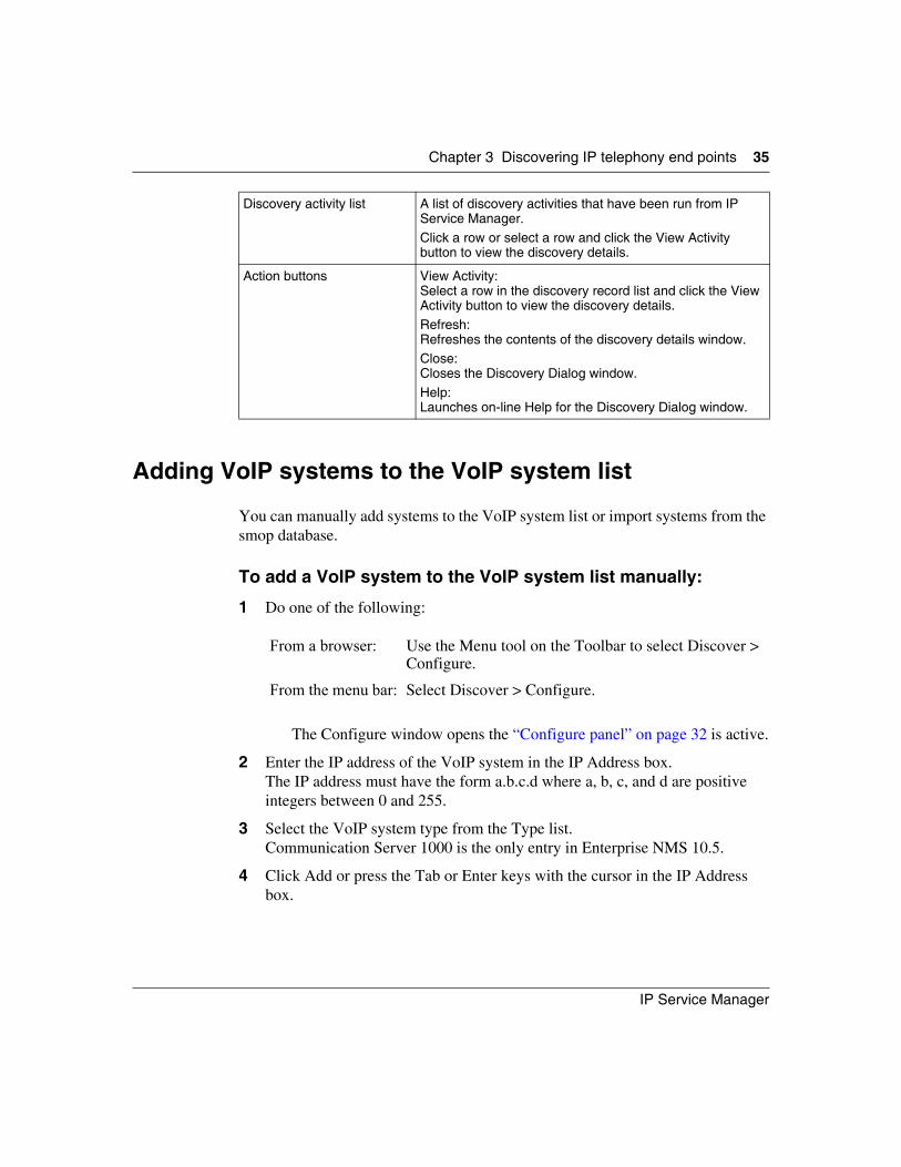
Discovery activity list A list of discovery activities that have been run from IP Service Manager. Click a row or select a row and click the View Activity button to view the discovery details.
Action buttons View Activity: Select a row in the discovery record list and click the View Activity button to view the discovery details.Refresh:Refreshes the contents of the discovery details window.Close:Closes the Discovery Dialog window.Help:Launches on-line Help for the Discovery Dialog window.
From a browser: Use the Menu tool on the Toolbar to select Discover > Configure.
From the menu bar: Select Discover > Configure.
36 Chapter 3 Discovering IP telephony end points
321540-B
The IP address and type of the VoIP system are added to the VoIP system list; the checkbox is selected.
To import VoIP systems from the Enterprise NMS smop database:
1 Do one of the following:
The Configure window opens, the “Configure panel” on page 32 is active.
2 Click Import.A confirmation dialog window opens.
3 Click Yes.All VoIP systems in the smop database are added to the VoIP system list.
Note: If the IP address box is not within the view domain of the user, the VoIP system is not added to the VoIP system list.
For more information on view domains, see the Security guide (part number 321536-B) or, from within the Help system, click Access Control Administration online Help.
From a browser: Use the Menu tool on the Toolbar to select Discover > Configure.
From the menu bar: Select Discover > Configure.
Note: If the IP address box is not within the view domain of the user, the VoIP system is not added to the VoIP system list.
For more information on view domains, see the Security guide (part number 321536-B) or, from within the Help system, click Access Control Administration online Help.
Chapter 3 Discovering IP telephony end points 37
IP Service Manager
Discovering the end points
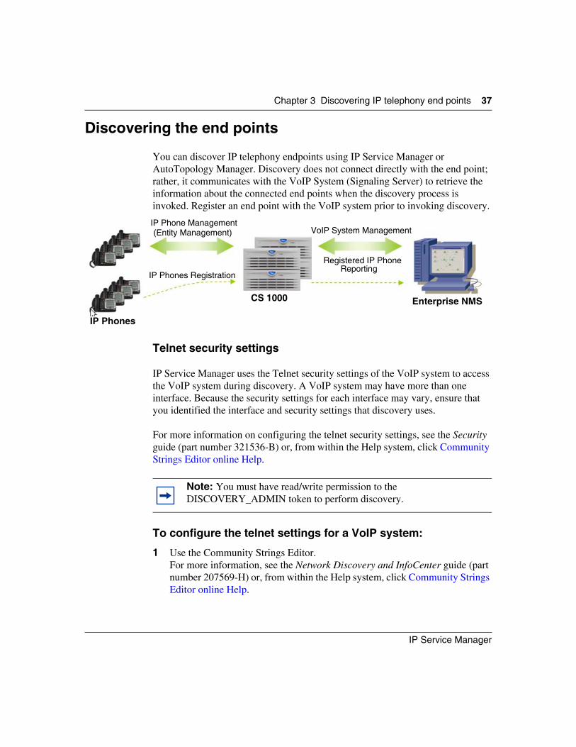
You can discover IP telephony endpoints using IP Service Manager or AutoTopology Manager. Discovery does not connect directly with the end point; rather, it communicates with the VoIP System (Signaling Server) to retrieve the information about the connected end points when the discovery process is invoked. Register an end point with the VoIP system prior to invoking discovery.
Telnet security settings
IP Service Manager uses the Telnet security settings of the VoIP system to access the VoIP system during discovery. A VoIP system may have more than one interface. Because the security settings for each interface may vary, ensure that you identified the interface and security settings that discovery uses.
For more information on configuring the telnet security settings, see the Security guide (part number 321536-B) or, from within the Help system, click Community Strings Editor online Help.
To configure the telnet settings for a VoIP system:
1 Use the Community Strings Editor.For more information, see the Network Discovery and InfoCenter guide (part number 207569-H) or, from within the Help system, click Community Strings Editor online Help.
Note: You must have read/write permission to the DISCOVERY_ADMIN token to perform discovery.
IP Phone Management(Entity Management)
IP Phones Registration
IP Phones
CS 1000
Registered IP PhoneReporting
Enterprise NMS
VoIP System Management
38 Chapter 3 Discovering IP telephony end points
321540-B
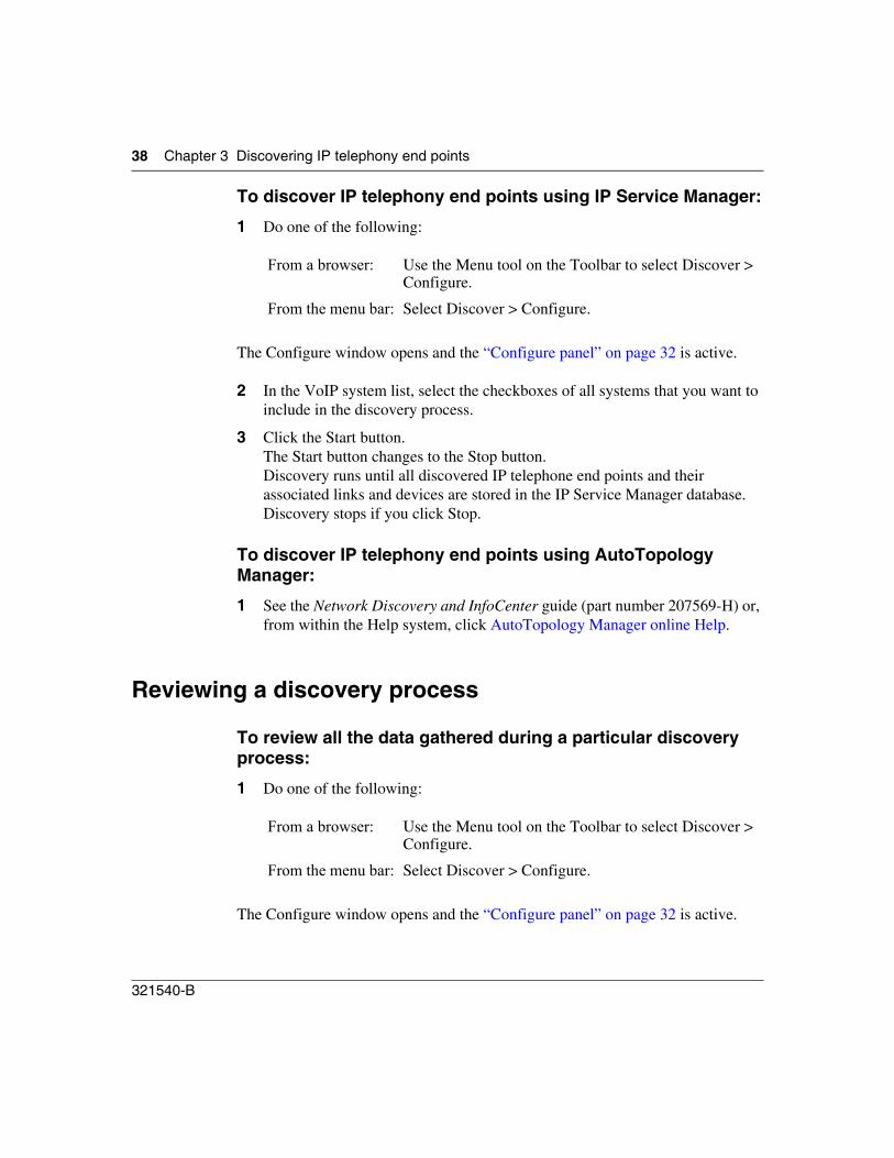
To discover IP telephony end points using IP Service Manager:
1 Do one of the following:
The Configure window opens and the “Configure panel” on page 32 is active.
2 In the VoIP system list, select the checkboxes of all systems that you want to include in the discovery process.
3 Click the Start button.The Start button changes to the Stop button.Discovery runs until all discovered IP telephone end points and their associated links and devices are stored in the IP Service Manager database.Discovery stops if you click Stop.
To discover IP telephony end points using AutoTopology Manager:
1 See the Network Discovery and InfoCenter guide (part number 207569-H) or, from within the Help system, click AutoTopology Manager online Help.
Reviewing a discovery process
To review all the data gathered during a particular discovery process:
1 Do one of the following:
The Configure window opens and the “Configure panel” on page 32 is active.
From a browser: Use the Menu tool on the Toolbar to select Discover > Configure.
From the menu bar: Select Discover > Configure.
From a browser: Use the Menu tool on the Toolbar to select Discover > Configure.
From the menu bar: Select Discover > Configure.
Chapter 3 Discovering IP telephony end points 39
IP Service Manager
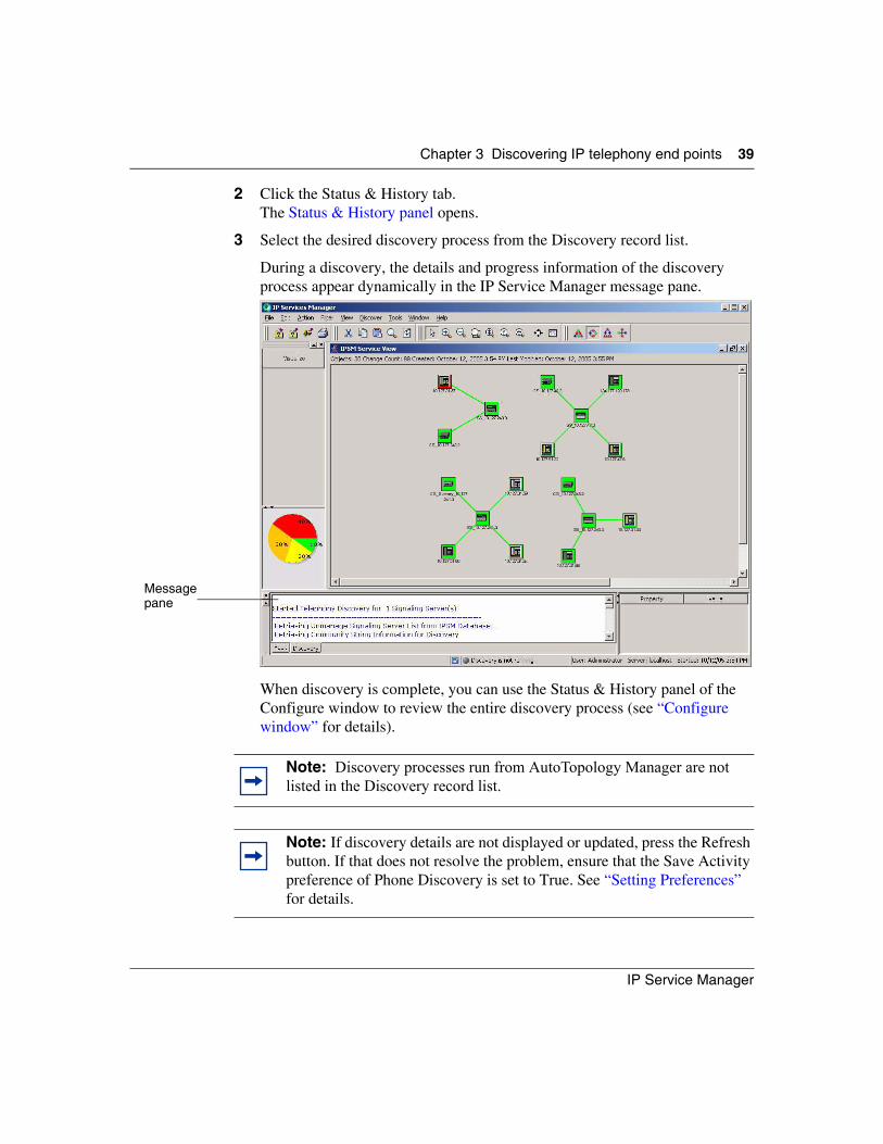
2 Click the Status & History tab.The Status & History panel opens.
3 Select the desired discovery process from the Discovery record list.
During a discovery, the details and progress information of the discovery process appear dynamically in the IP Service Manager message pane.
When discovery is complete, you can use the Status & History panel of the Configure window to review the entire discovery process (see “Configure window” for details).
Note: Discovery processes run from AutoTopology Manager are not listed in the Discovery record list.
Note: If discovery details are not displayed or updated, press the Refresh button. If that does not resolve the problem, ensure that the Save Activity preference of Phone Discovery is set to True. See “Setting Preferences” for details.
Message pane
40 Chapter 3 Discovering IP telephony end points
321540-B
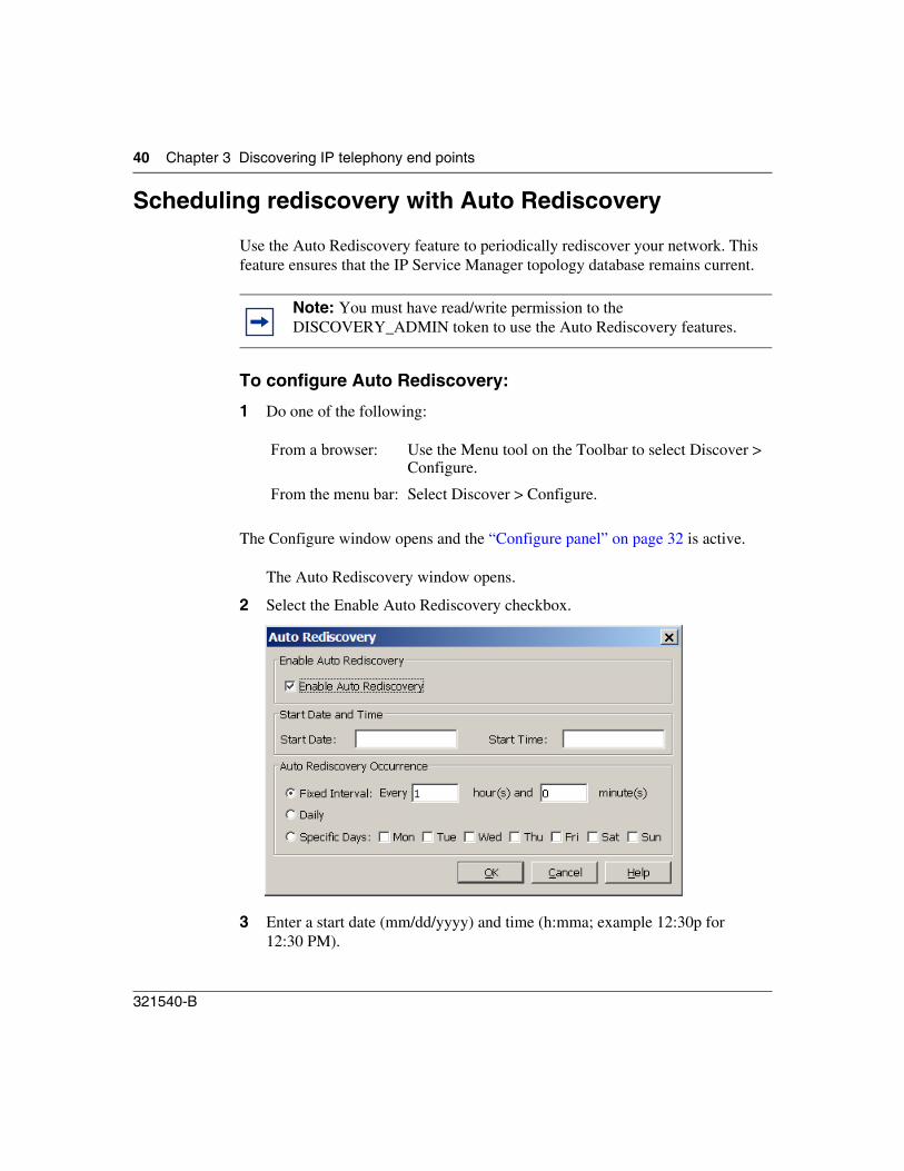
Scheduling rediscovery with Auto Rediscovery
Use the Auto Rediscovery feature to periodically rediscover your network. This feature ensures that the IP Service Manager topology database remains current.
To configure Auto Rediscovery:
1 Do one of the following:
The Configure window opens and the “Configure panel” on page 32 is active.
The Auto Rediscovery window opens.
2 Select the Enable Auto Rediscovery checkbox.
3 Enter a start date (mm/dd/yyyy) and time (h:mma; example 12:30p for 12:30 PM).
Note: You must have read/write permission to the DISCOVERY_ADMIN token to use the Auto Rediscovery features.
From a browser: Use the Menu tool on the Toolbar to select Discover > Configure.
From the menu bar: Select Discover > Configure.
Chapter 3 Discovering IP telephony end points 41
IP Service Manager
4 Either:
a Select Fixed Interval and specify the length of the interval in hours and minutes (whole numbers). An empty field is interpreted as 0. Rediscovery runs periodically, with the period set by the length of the interval.
Or
b Select Daily to have rediscovery run every day at the Start Time, or select Specific Days to have rediscovery run only on the days you select.
5 Click OK.
Modifying VoIP system information
To modify VoIP system information after you add the system to the VoIP system list:
1 Do one of the following:
The Configure window opens and the “Configure panel” on page 32 is active.
2 In the VoIP system list, click in the table cell that contains the information that you want to change.You can edit the IP address. Currently, the only type of VoIP system is Communication Server 1000.
From a browser: Use the Menu tool on the Toolbar to select Discover > Configure.
From the menu bar: Select Discover > Configure.
42 Chapter 3 Discovering IP telephony end points
321540-B
Deleting VoIP systems from the VoIP system list
To delete one or more VoIP systems from the VoIP system list:
1 Do one of the following:
The Configure window opens and the “Configure panel” on page 32 is active.
2 Select the checkbox next to the system or systems that you want to delete.
3 Click the Delete button.A confirmation dialog window opens.
4 Click Yes.The checked systems are removed from the VoIP system list. This does not delete the system from the IP Service Manager database or the Enterprise NMS smop database.
Saving the VoIP system list
To save the VoIP system list:
1 Do one of the following:
The Configure window opens and the “Configure panel” on page 32 is active.
From a browser: Use the Menu tool on the Toolbar to select Discover > Configure.
From the menu bar: Select Discover > Configure.
Note: Be sure to clear the checkbox for any systems that you do not want to delete.
From a browser: Use the Menu tool on the Toolbar to select Discover > Configure.
From the menu bar: Select Discover > Configure.
Chapter 3 Discovering IP telephony end points 43
IP Service Manager
2 Click the Save button.The IP address and type of the VoIP systems are saved to the IP Service Manager database in a csv-formatted file.
Note: If you run a discovery after modifying the VoIP system list, the list is automatically saved and a separate save action is not required.

44 Chapter 3 Discovering IP telephony end points
321540-B
45
IP Service Manager
Chapter 4Displaying the network and devices
The IP Service Manager provides two ways to view the network and its devices:
Activities for displaying the IP telephony network and devices include:
• “Displaying the service view or VoIP system” on page 45
• “Displaying the converged view or connectivity” on page 46
• “Displaying all IP phones for a VoIP system” on page 47
• “Displaying the properties of an object” on page 48
• “Creating a new object” on page 49
• “Refreshing a view” on page 50.
Displaying the service view or VoIP system
Service View and Show VoIP System generate a view that includes only telephony devices and links. That is, only components that are actively engaged in voice call processing are shown.
Service View, Show VoIP System
Service View and Show VoIP System generate a view that includes only IP telephony devices and links; that is, the logical connections between the IP telephony devices.
Converged View, Show Connectivity
Converged View and Show Connectivity generate a view that includes all devices and links; that is, the physical network connections and devices.
46 Chapter 4 Displaying the network and devices
321540-B
To display the service view of the entire network:
1 Do one of the following:
A service view of the network appears in the view panel.
To display the service view of an object:
1 Select the object in the view panel, either the icon in a graphical display or the table row in a tabular display.
2 Do one of the following:
• Use the Menu bar or menu tool to navigate to Action > Show VoIP System.
• Right-click the object and select Show VoIP System from the shortcut menu.
The service view of the object appears in the view panel.
Displaying the converged view or connectivity
Converged View and Show Connectivity generate a view that includes all devices and links. That is, the entire converged voice and data path is shown.
From a browser: Use the Menu tool on the Toolbar to select View > Service View.
From the menu bar: Select View > Service View.
Note: Showing the service components is not applicable to all objects. If the Show VoIP System item is not active, then the action does not apply to the selected object.
Chapter 4 Displaying the network and devices 47
IP Service Manager
To display the converged view of the entire network:
1 Do one of the following:
A converged view of the network appears in the view panel.
To display the converged view of an object:
1 Select the object in the view panel, either the icon in a graphical display or the table row in a tabular display.
2 Do one of the following:
• Use the Menu bar or menu tool to navigate to Action > Show Connectivity.
• Right-click the object and select Show Connectivity from the shortcut menu.
The converged view of the object appears in the view panel.
Displaying all IP phones for a VoIP system
To display all IP phones registered with a VoIP system:
1 In the view panel, select the signaling server for the required VoIP system. Select the icon in a graphical display or the table row in a tabular display.
2 Do one of the following:
From a browser: Use the Menu tool on the Toolbar to select View > Converged View.
From the menu bar: Select View > Converged View.
• From a browser: Use the Menu tool on the Toolbar to select Action > Show IP Phones.
• From the menu bar:
Select Action > Show IP Phones.
48 Chapter 4 Displaying the network and devices
321540-B
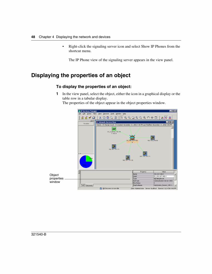
• Right-click the signaling server icon and select Show IP Phones from the shortcut menu.
The IP Phone view of the signaling server appears in the view panel.
Displaying the properties of an object
To display the properties of an object:
1 In the view panel, select the object, either the icon in a graphical display or the table row in a tabular display.The properties of the object appear in the object properties window.
Object properties window
Chapter 4 Displaying the network and devices 49
IP Service Manager
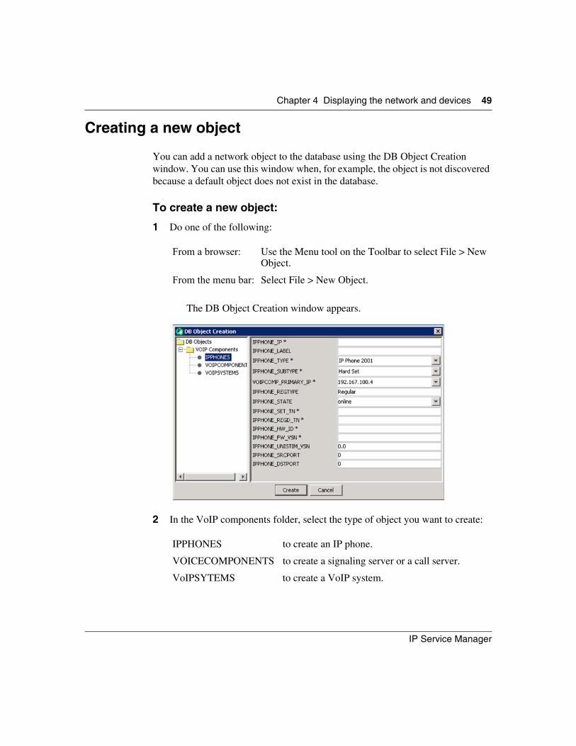
Creating a new object
You can add a network object to the database using the DB Object Creation window. You can use this window when, for example, the object is not discovered because a default object does not exist in the database.
To create a new object:
1 Do one of the following:
The DB Object Creation window appears.
2 In the VoIP components folder, select the type of object you want to create:
From a browser: Use the Menu tool on the Toolbar to select File > New Object.
From the menu bar: Select File > New Object.
IPPHONES to create an IP phone.
VOICECOMPONENTS to create a signaling server or a call server.
VoIPSYTEMS to create a VoIP system.
50 Chapter 4 Displaying the network and devices
321540-B
3 Use the component descriptions provided in “Displaying the properties of an object” to datafill the boxes appropriately for the selected object.
4 Click Create.A Creation Succeeded message confirms that creation was successful.The new object is added to the database and appears in a window in the view panel.
For more information on creating and managing new objects, see the Network Discovery and InfoCenter guide (part number 207569-H) or, from within the Help system, click InfoCenter online Help.
Refreshing a view
To refresh the contents of the active window:
1 Do one of the following:
The view in the active window is updated with the current status of the devices and links.
From a browser: Use the Menu tool on the Toolbar to select View > Refresh View.
From the menu bar: Select View > Refresh View.
51
IP Service Manager
Chapter 5Managing filters
The IP Service Manager has two default filters (Show all IP Phones and Show All VoIP Systems) and provides a comprehensive mechanism for creating custom filters.You can import filters and export both filters and filtered data. A filter manager offers a central launch point for filter functions.
Filter activities include:
• familiarizing yourself with the Filter windows; see “Filter Editor window” on page 52 and “Filter Definition window” on page 54
• “Creating, modifying, and deleting filters” on page 55
• “Running a filter” on page 57
• “Importing and exporting filters and filter data” on page 58
52 Chapter 5 Managing filters
321540-B
Filter Editor window
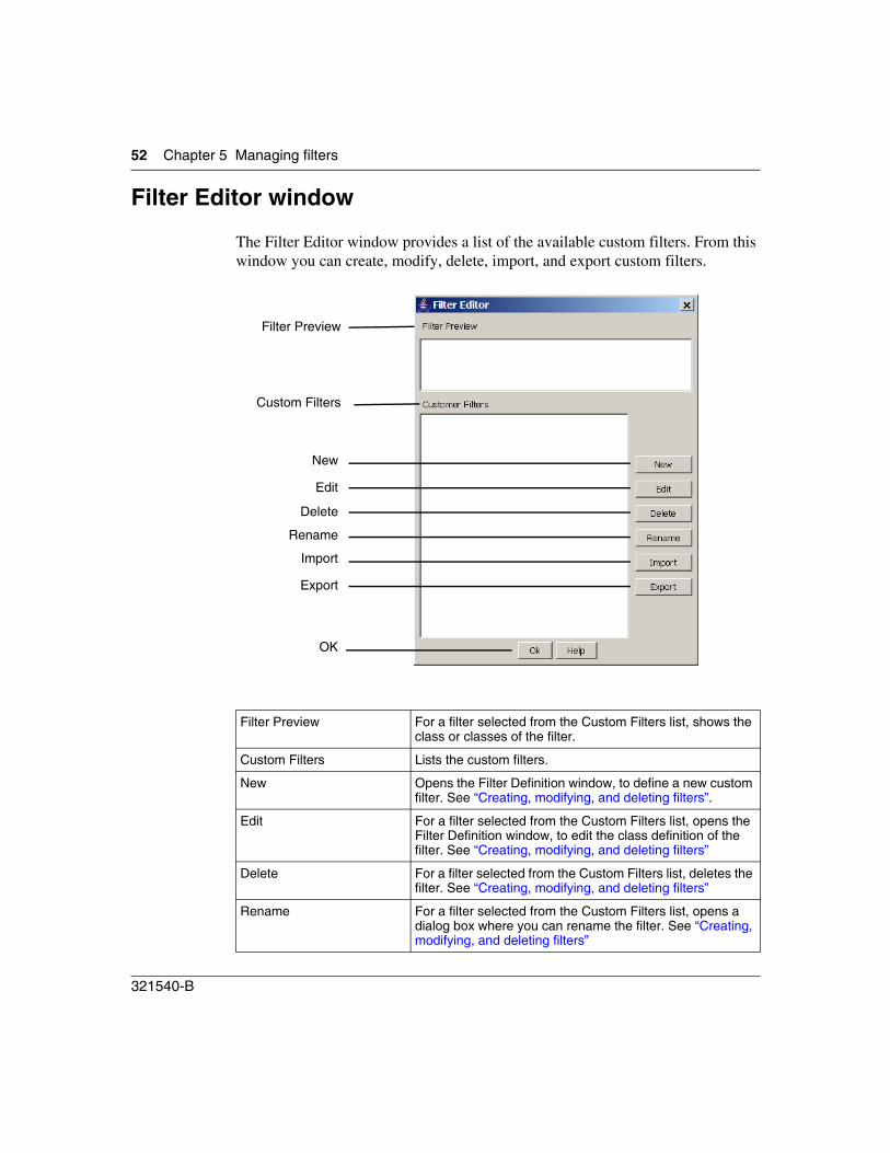
The Filter Editor window provides a list of the available custom filters. From this window you can create, modify, delete, import, and export custom filters.
Filter Preview For a filter selected from the Custom Filters list, shows the class or classes of the filter.
Custom Filters Lists the custom filters.
New Opens the Filter Definition window, to define a new custom filter. See “Creating, modifying, and deleting filters”.
Edit For a filter selected from the Custom Filters list, opens the Filter Definition window, to edit the class definition of the filter. See “Creating, modifying, and deleting filters”
Delete For a filter selected from the Custom Filters list, deletes the filter. See “Creating, modifying, and deleting filters”
Rename For a filter selected from the Custom Filters list, opens a dialog box where you can rename the filter. See “Creating, modifying, and deleting filters”
Filter Preview
Custom Filters
New
Edit
Delete
Rename
Import
Export
OK
Chapter 5 Managing filters 53
IP Service Manager
Import Click to import a custom filter or set of custom filters. See “Importing and exporting filters and filter data”.
Export Click to export the selected custom filter. See “Importing and exporting filters and filter data”.
OK Click to complete the transaction and close the Filter Editor window.
54 Chapter 5 Managing filters
321540-B
Filter Definition window
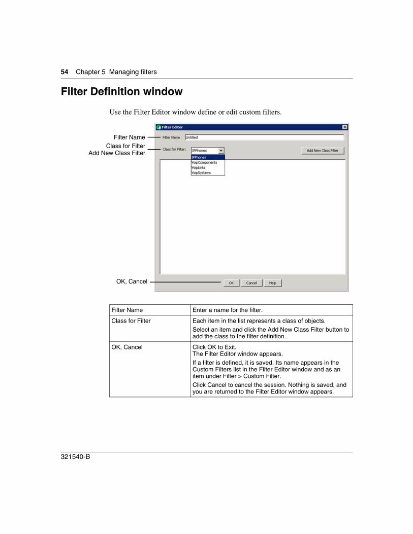
Use the Filter Editor window define or edit custom filters.
Filter Name Enter a name for the filter.
Class for Filter Each item in the list represents a class of objects.Select an item and click the Add New Class Filter button to add the class to the filter definition.
OK, Cancel Click OK to Exit.The Filter Editor window appears.If a filter is defined, it is saved. Its name appears in the Custom Filters list in the Filter Editor window and as an item under Filter > Custom Filter.Click Cancel to cancel the session. Nothing is saved, and you are returned to the Filter Editor window appears.
Filter NameClass for Filter
Add New Class Filter
OK, Cancel
Chapter 5 Managing filters 55
IP Service Manager
Creating, modifying, and deleting filters
You can use IP Service Manager to create, modify, and delete custom filters. Yo can use custom filters to search the database for all objects of a specific type or types.
To create a custom filter:
1 Do one of the following:
The “Filter Editor window” on page 52 window appears.
2 Click the New button.The “Filter Definition window” on page 54 window appears.
3 In the Filter Name box, enter the name of the new filter.
4 From the Class for Filter list, select the class of classes that you want to add (es) to the filter.
5 Click Add New Class Filter The class is added to the filter definition.
6 Add additional classes to meet your requirements.
7 When you add all classes, click OK.The Filter Definition window closes and Filter Editor window appears. The new filter appears in the Customer Filters list.
To modify a custom filter:
1 Do one of the following:
From a browser:
Use the Menu tool on the Toolbar to select Filter > Custom Filter > Create New.
From the menu bar:
Select Filter > Custom Filter > Create New.
From a browser:
Use the Menu tool on the Toolbar to select Filter > Filter Manager.
From the menu bar:
Select Filter > Filter Manager.
56 Chapter 5 Managing filters
321540-B
The “Filter Editor window” on page 52 window appears.
2 From the Custom Filters list, select the filter that you want to modify.
3 Do one of the following:
To view the classes defined for a custom filter:
1 Do one of the following:
The “Filter Editor window” on page 52 window appears.
2 From the Custom Filters list, select the desired filter.The classes defined for the filter appear in the Filter Preview window, above the Custom Filter list.
To rename the filter: • Click Rename.
• In the Rename Filter window enter the new name.
• Click OK.
To delete the filter: • Click Delete.
• Click yes when prompted.
To change the filter definition:
• Click Edit. The Filter Definition window opens.
• Add or remove object class definitions to meet your requirements.
From a browser:
Use the Menu tool on the Toolbar to select Filter > Filter Manager.
From the menu bar:
Select Filter > Filter Manager.
Chapter 5 Managing filters 57
IP Service Manager
Running a filter
When you run a filter, the database is searched for the type of object or objects defined by the filter, and the result appears in tabular format. In addition to user-defined custom filters, IP Service Manager provides two default filters: Show All IP Phones and Show All VoIP Systems.
Show All IP Phones generates a list of all IP phones for all VoIP systems in the network. Show All VoIP Systems generates a list of all signaling servers in the network.
To generate a list of all IP phones:
1 Do one of the following:
A list of all IP phones appear in tabular format in the view panel.
To generate a list of all VoIP systems:
1 Do one of the following:
A lists of all VoIP systems appear in tabular format in the view panel.
From a browser:
Use the Menu tool on the Toolbar to select Filter > Show All IP Phones.
From the menu bar:
Select Filter > Show All IP Phones.
From a browser:
Use the Menu tool on the Toolbar to select Filter > Show All VoIP Systems.
From the menu bar:
Select Filter > Show All VoIP Systems.
58 Chapter 5 Managing filters
321540-B
To run a custom filter:
1 Do one of the following:
A list of the custom filters appears.
2 Click the name of the filter you want to run.The results of the filter appears in tabular format in the view panel.
Importing and exporting filters and filter data
You can import and export filter definitions, allowing users and different workstations to share filters. Also, you can export the data generated by running a filter for analysis in other applications such as a spreadsheet. All exported files are csv-formatted.
To export one custom filter:
1 Do one of the following:
The “Filter Editor window” on page 52 window appears.
2 From the Custom Filter list select the filter to be exported.
From a browser:
Use the Menu tool on the Toolbar to select Filter > Custom Filter.
From the menu bar:
Select Filter > Custom Filter.
Note: When you export filters, the original name or names of the filters are saved in the exported file, regardless of the name of the file itself.
From a browser:
Use the Menu tool on the Toolbar to select Filter > Filter Manager.
From the menu bar:
Select Filter > Filter Manager.
Chapter 5 Managing filters 59
IP Service Manager
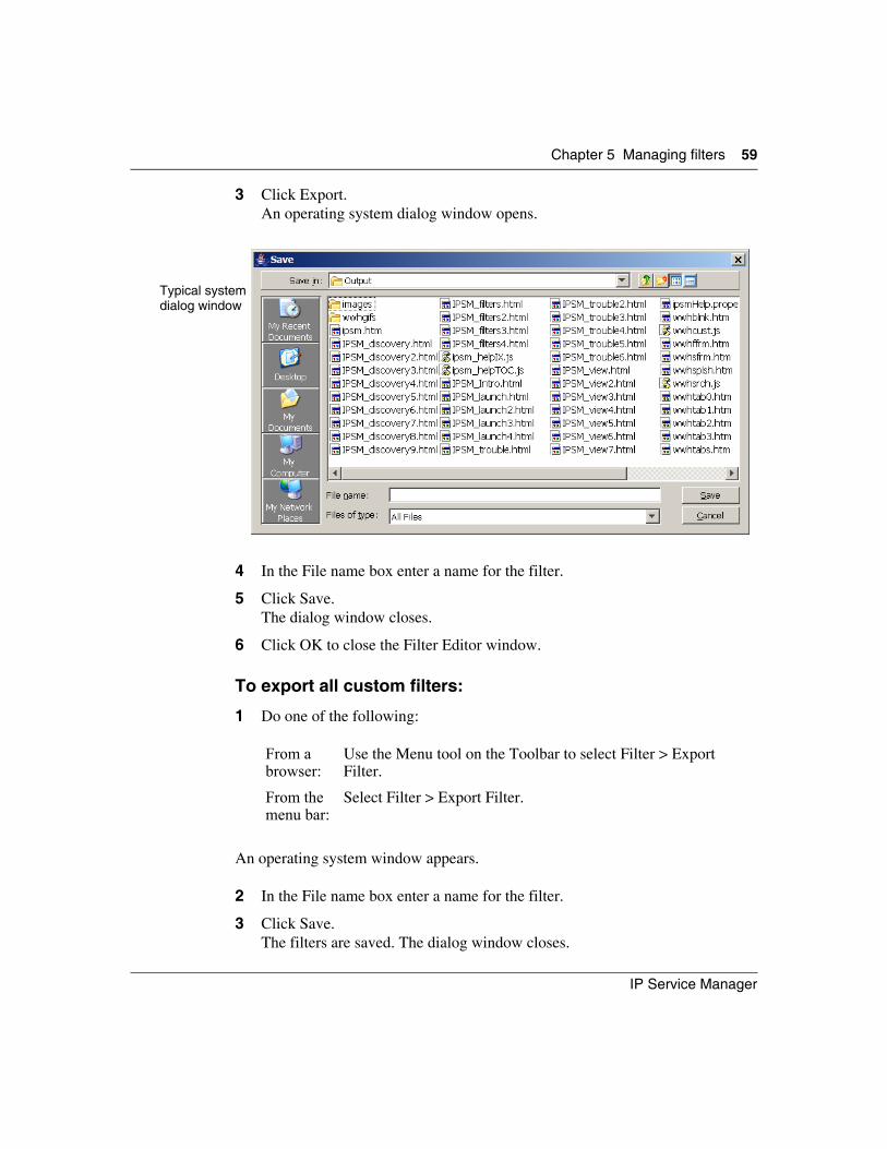
3 Click Export.An operating system dialog window opens.
4 In the File name box enter a name for the filter.
5 Click Save.The dialog window closes.
6 Click OK to close the Filter Editor window.
To export all custom filters:
1 Do one of the following:
An operating system window appears.
2 In the File name box enter a name for the filter.
3 Click Save.The filters are saved. The dialog window closes.
From a browser:
Use the Menu tool on the Toolbar to select Filter > Export Filter.
From the menu bar:
Select Filter > Export Filter.
Typical systemdialog window
60 Chapter 5 Managing filters
321540-B
To import a filter or set of filters:
1 From the menu bar or by using the Menu tool on the Toolbar, do one of the following:
• Select Filter > Import Filter (Browser path: Menu tool on Toolbar > Filter > Import Filter).
• Select Filter > Filter Manager (Browser path: Menu tool on Toolbar > Filter > Filter Manager).When the Filter Dialog window opens, click Import.
An operating system dialog window appears.
2 Do one of the following:
• Browse the file list to locate the desired filter file and click the file name.The name of the filter appears in the File name box.
• In the File name box enter a name for the filter.
3 Click Open.
4 The filter or filters are added to the Custom Filter list.
To export the data in a filter table:
1 Run the desired filter (see “Running a filter”).
2 Make the data table the active window in the view panel.
3 Do one of the following:
An operating system dialog window appears.
Note: If the name of a filter in the imported file matches a name in the Custom Filter list, the Filter Editor window opens, if it is not already open, and you are prompted to replace the existing filter or cancel the import for that particular filter. Other filters in the file are still imported.
From a browser:
Use the Menu tool on the Toolbar to select File > Export Content.
From the menu bar:
Select Filter > Export Filter.

Chapter 5 Managing filters 61
IP Service Manager
4 In the File name box enter a name for the filter.
5 Click Save.The filter content is saved. The dialog window closes.

62 Chapter 5 Managing filters
321540-B
63
IP Service Manager
Chapter 6Troubleshooting the IP telephony network
The Communication Server 1000 (CS 1000) monitors and reports voice quality metrics dynamically; that is, while calls are in progress. The IP Service Manager uses this data to monitor both IP telephony devices and voice quality. Thus, IP Service Manager provides proactive voice quality management of Nortel IP telephony networks.
IP Service Manager processes traps generated by the following CS 1000 events:
• R-Value trap (warning and unacceptable) to report voice quality degradation
• R-Value clear trap (warning and unacceptable) to notify voice service restoration
• TN registered trap to notify that a new IP end point is joining the service
• TN deregister trap to notify that an IP end point is losing the service
• Superping traps to poll signaling server and call server for availability
Handling faults
The fault status of a device appears in both the visualization map and the filter table. Generally, all monitoring and troubleshooting activities for a device are available by right-clicking the icon of the device on the visualization map or its row in a filter table.
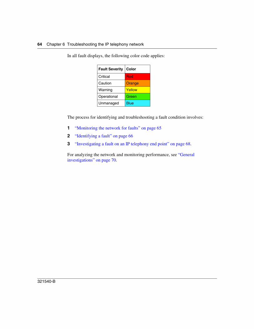
64 Chapter 6 Troubleshooting the IP telephony network
321540-B
In all fault displays, the following color code applies:
The process for identifying and troubleshooting a fault condition involves:
1 “Monitoring the network for faults” on page 65
2 “Identifying a fault” on page 66
3 “Investigating a fault on an IP telephony end point” on page 68.
For analyzing the network and monitoring performance, see “General investigations” on page 70.
Fault Severity Color
Critical Red
Caution Orange
Warning Yellow
Operational Green
Unmanaged Blue
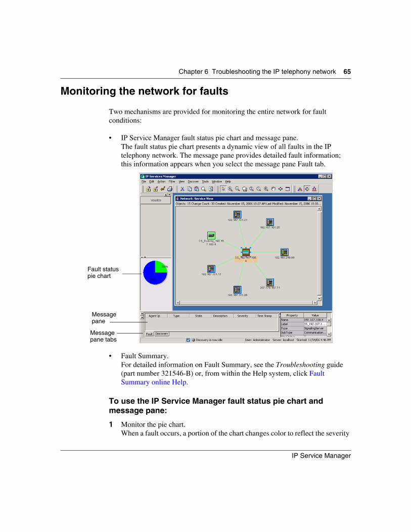
Chapter 6 Troubleshooting the IP telephony network 65
IP Service Manager
Monitoring the network for faults
Two mechanisms are provided for monitoring the entire network for fault conditions:
• IP Service Manager fault status pie chart and message pane.The fault status pie chart presents a dynamic view of all faults in the IP telephony network. The message pane provides detailed fault information; this information appears when you select the message pane Fault tab.
• Fault Summary.For detailed information on Fault Summary, see the Troubleshooting guide (part number 321546-B) or, from within the Help system, click Fault Summary online Help.
To use the IP Service Manager fault status pie chart and message pane:
1 Monitor the pie chart.When a fault occurs, a portion of the chart changes color to reflect the severity
Fault status pie chart
Message pane
Message pane tabs
66 Chapter 6 Troubleshooting the IP telephony network
321540-B
of the fault.Simultaneously, a message appears in the message pane to identify the object with the fault and provide fault information.
To use Fault Summary:
1 Move the cursor to an empty area of the IP Service Manager view panel and click, so that no objects or table rows are selected.
2 Use the menu bar or Menu tool to navigate to Tools > Fault > Events > Fault View.The Fault Summary tool opens.
3 Under the Faults folder, expand the Severity based folder.
4 Periodically check the alarm status or set the Fault Summary fault notification beep.
For more information on Fault Summary, see the Troubleshooting guide (part number 321546-B) or, from within the Help system, click Fault Summary online Help.
Identifying a fault
You can use a graphical display, the message pane, or filtered data to identify a fault.
To identify a fault using a graphical display:
1 Use the menu bar or Menu tool to navigate to View > Service View.The service network diagram appears.(See “Displaying the service view or VoIP system” for details.)
Objects are color-coded to show their highest fault severity.
2 Scan the diagram for objects with a fault condition.
3 Select an object with a fault.Details of the fault are provided in the message pane when you select the Fault tab.
Chapter 6 Troubleshooting the IP telephony network 67
IP Service Manager
To identify a fault using the message pane:
1 Select the message pane Fault tab.Fault messages are color-coded to show fault status of the object.
2 Scroll through the message pane to locate faults.
3 Review the fault messages to determine priority for further investigation and resolution.
To identify a fault using filtered data:
1 Create a custom filter for the type or types of objects you want to monitor. For all IP phones or all VoIP systems, you can use the default filters. See “Managing filters” for more information.
2 Run the filter.Each row in the filter table is color-coded to show fault severity.
3 Scan the filter table for faults.
4 When a fault is found, click on the row. Additional information on the fault appears in the message pane when you select the Fault tab.
To find an object in a large network using a graphical display:
1 If the network is not already displayed, use the menu bar or Menu tool to navigate to View > Service View.The service network diagram is displayed.(See “Displaying the service view or VoIP system” for details.)
2 Use the IP Service Manager message pane or Fault Summary to obtain the IP address of the object with the fault (Device Label in Fault Summary).See “Monitoring the network for faults” for details.
3 Open the Find dialog box by doing one of the following:
• Use the menu bar or Menu tool to navigate to File > Locate.
• On the toolbar, click Find.
4 In the Label box, enter the IP address and Device Label of the object.
5 Click Find Next.IP Service Manager locates the object and highlights it on the service network diagram. The color of the icon indicates the fault severity.
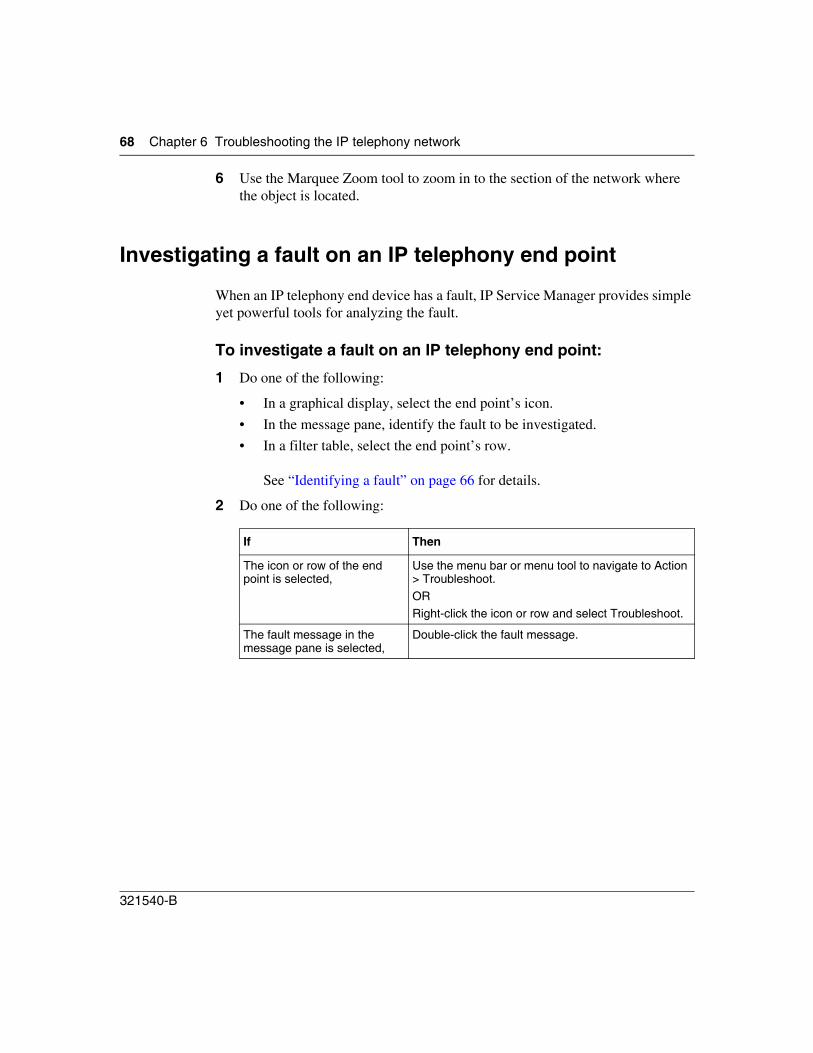
68 Chapter 6 Troubleshooting the IP telephony network
321540-B
6 Use the Marquee Zoom tool to zoom in to the section of the network where the object is located.
Investigating a fault on an IP telephony end point
When an IP telephony end device has a fault, IP Service Manager provides simple yet powerful tools for analyzing the fault.
To investigate a fault on an IP telephony end point:
1 Do one of the following:
• In a graphical display, select the end point’s icon.
• In the message pane, identify the fault to be investigated.
• In a filter table, select the end point’s row.
See “Identifying a fault” on page 66 for details.
2 Do one of the following:
If Then
The icon or row of the end point is selected,
Use the menu bar or menu tool to navigate to Action > Troubleshoot.ORRight-click the icon or row and select Troubleshoot.
The fault message in the message pane is selected,
Double-click the fault message.
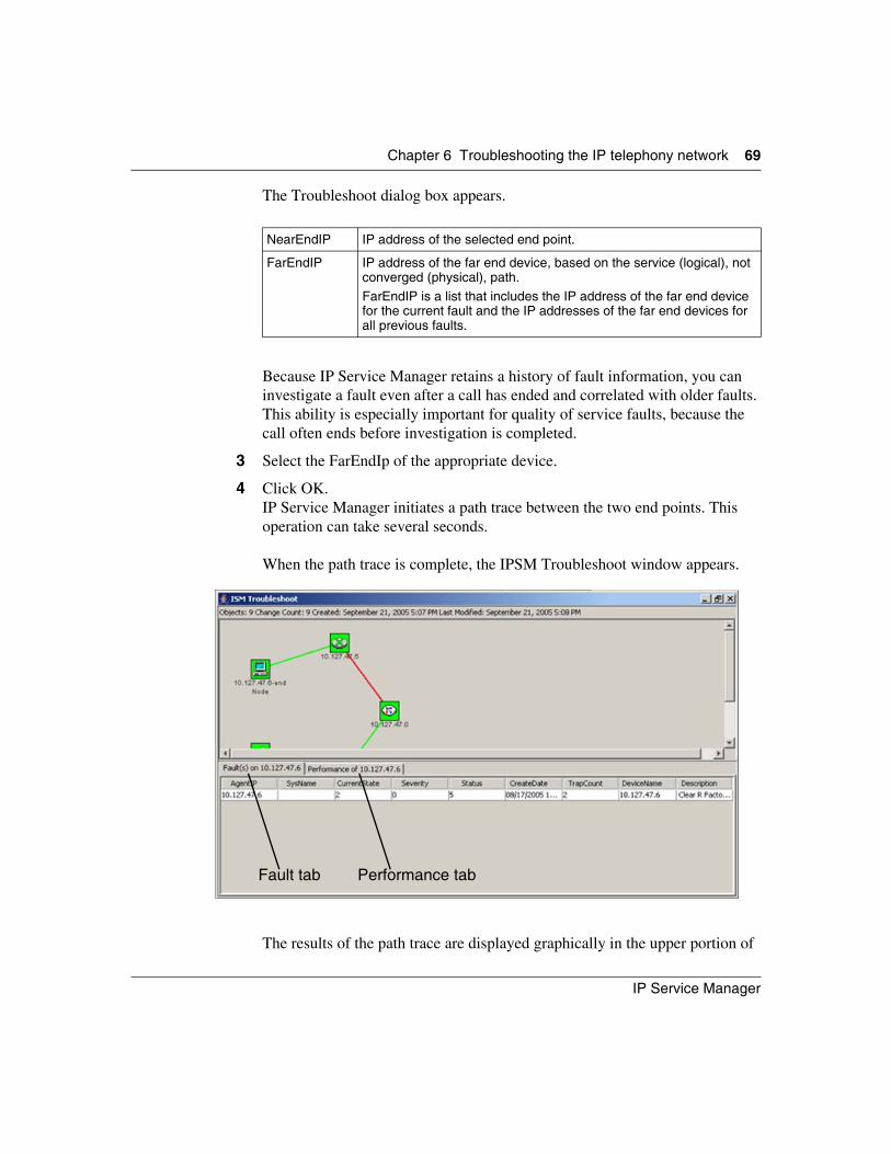
Chapter 6 Troubleshooting the IP telephony network 69
IP Service Manager
The Troubleshoot dialog box appears.
Because IP Service Manager retains a history of fault information, you can investigate a fault even after a call has ended and correlated with older faults. This ability is especially important for quality of service faults, because the call often ends before investigation is completed.
3 Select the FarEndIp of the appropriate device.
4 Click OK.IP Service Manager initiates a path trace between the two end points. This operation can take several seconds.
When the path trace is complete, the IPSM Troubleshoot window appears.
The results of the path trace are displayed graphically in the upper portion of
NearEndIP IP address of the selected end point.
FarEndIP IP address of the far end device, based on the service (logical), not converged (physical), path.FarEndIP is a list that includes the IP address of the far end device for the current fault and the IP addresses of the far end devices for all previous faults.
Fault tab Performance tab
70 Chapter 6 Troubleshooting the IP telephony network
321540-B
the window. The lower portion of the window provides fault and performance information.
The path trace identifies all IP telephony devices and all layer 2 and layer 3 data devices in the path.
When you select the Fault tab, the latest and highest severity faults for the selected device appear.
When you select the Performance tab, performance statistics for the selected device appear.
5 Select devices in the path trace route to obtain device-specific fault and performance information.
6 Use the collected information to analyze the problem. If more information is required, broaden the investigation. See “General investigations” for details.
General investigations
The IP Service Manager Troubleshoot tool is available only when a fault condition occurs on an end point. The following tools are available for general investigations:
• Ping
• TraceRoute
• Path Trace
• Manage/Unmanage
• Fault Summary
• OmniView
• InfoCenter
To access these tools, do one of the following:
• Use the menu bar or menu tool to navigate to the Action menu (Ping, TraceRoute, Path Trace, Manage/Unmanage) and the Tools menu (Fault Summary, OmniView, and InfoCenter).
Chapter 6 Troubleshooting the IP telephony network 71
IP Service Manager
• Right-click the icon or row representing the object, and select the tool.
Ping
Ping provides confirmation of connectivity to the device at the specified IP address. Ping applies to IP phones only.
To use ping:
1 Do one of the following:
• In a graphical display, select the end point icon.
• In a filter table, select the end point row.
2 Do one of the following:
• From the menu bar, choose Action > Ping.
• Right-click the row or icon and select Ping.
The Ping Input dialog box appears. The Source Address box contains the IP address of the selected end point.
3 In the Destination Address box enter the IP address of the destination end point.
4 Enter the number of retries in the Retry box.
5 Click OK.The results of the ping appear in the IP EndPoint Ping Output window.
TraceRoute
TraceRoute is a utility that records the route (layer 3 devices) between two IP phones and calculates the time each hop takes. TraceRoute applies to IP phones only.
To use TraceRoute:
1 Do one of the following:
Note: Available tools depend on the type of object.
72 Chapter 6 Troubleshooting the IP telephony network
321540-B
• In a graphical display, select the end point icon.
• In a filter table, select the end point row.
2 Do one of the following:
• From the menu bar, choose Action > TraceRoute.
• Right-click the row or icon and select TraceRoute.
The TraceRoute Input dialog box appears. The Source Address box contains the IP address of the selected end point.
3 In the Destination Address box enter the IP address of the destination end point.
4 In the No. of hops box enter the number of hops.
5 Click OK.The results of the traceroute action appear in the TraceRoute window.
Path Trace
Path Trace provides a graphical representation of the live path between the source and destination IP address, and includes all layer 2 and layer 3 devices.
To use Path Trace:
1 Do one of the following:
• In a graphical display, select the end point icon.
• In a filter table, select the end point row.
2 Do one of the following:
• From the menu bar, choose Action > Path Trace.
• Right-click the row or icon and select Path Trace.
The Enter Path Trace Information dialog box opens. The Src Address box contains the IP address of the selected end point.
3 In the Dest Address box enter the IP address of the destination end point.
4 Click OK.The results of the path trace appear in the Path Trace window.
Chapter 6 Troubleshooting the IP telephony network 73
IP Service Manager
Manage/Unmanage
When a device is discovered, it is in the managed state, and traps from the device are monitored. If a device is in an unmanaged state, traps are not monitored, and so the state of the device is unknown.
To change the management state:
1 Do one of the following:
• In a graphical display, select the end point icon.
• In a filter table, select the end point row.
2 Do one of the following:
• From the menu bar, choose Action > Manage/Unmanage.
• Right-click the row or icon and select Manage/Unmanage.
The management state of the device changes to the opposite state.
Fault Summary
To use Fault Summary:
1 Do one of the following:
• In a graphical display, select the end point icon.
• In a filter table, select the end point row.
2 Right-click the row or icon and select Fault > Event > Fault View.
Fault Summary is launched.
For more information on Fault Summary, see the Troubleshooting guide (part number 321546-B) or, from within the Help system, click Fault Summary online Help.
74 Chapter 6 Troubleshooting the IP telephony network
321540-B
OmniView
OmniView provides a suite of statistics that complement and augment the performance statistics reported by the Troubleshoot tool. OmniView allows an investigator to look at configuration information, real-time statistics, and IP connectivity on demand. For example, OmniView statistics could be used in the follow-up procedure for a Quality of Service event or a help desk-initiated ticket.
You can start OmniView from the menu bar by selecting Tools > Performance > OmniView or by selecting an end point and selecting Performance > OmniView. OmniView displays IP telephony information in the following panes:
• Ethernet statistics
• RTCP statistics
• Signaling statistics
• DHCP statistics
You can also start OmniView from the Command line with the -O option. For more information on OmniView, see the Performance Management guide (part number 321541-B) or, from within the Help system, click OmniView online Help.
InfoCenter
InfoCenter provides access to all Enterprise NMS tools and applications. Among other things, you can use these tools and applications to investigate the data devices in greater detail.
You can start InfoCenter from the menu bar by selecting Tools > Configuration > InfoCenter or by selecting an end point and selecting Configuration > InfoCenter from the right-click menu.
For more information on InfoCenter, see the Network Discovery and InfoCenter guide (part number 207569-H) or, from within the Help system, click InfoCenter online Help.
Chapter 6 Troubleshooting the IP telephony network 75
IP Service Manager
Performance statistics and definitions
Performance statistics for IP telephony networks are reported by two tools:
• IP Service Manager’s Troubleshoot tool
• OmniView
IP Service Manager provides a baseline of statistics to support troubleshooting activities. OmniView provides a broader set of statistics that support provisioning and engineering activities as well as troubleshooting.

76 Chapter 6 Troubleshooting the IP telephony network
321540-B
IP Service Manager
77
Index
AAccess Control for IP Service Manager 17
access control tokenIP Service Manager 17
all IP phones 47, 57
all VoIP systems 57
application launch panel 26
Auto Rediscovery 40
Cclass definition of a filter 56
classes of filters 55
Configure panel 32
Configure windows 31
conventions, text 13
converged view 45, 46
createfilters 55new object 49
Ddelete
filters 55VoIP systems 42
Device properties window 27
Discovering IP telephony end points 37
DiscoveryConfigure panel 32Configure windows 31Status & History panel 34
VoIP system list 35
displayall IP phones 47converged view 46logical connections 45object properties 48physical network connections and devices 46service view 45
Eexport
filter data 58filters 58
Ffault identification 66
fault managementFault Summary 73identifying a fault 66InfoCenter 74investigating a fault 68management state 73monitoring the network 65OmniView 74Path Trace 72ping 71statistics 75TraceRoute 71
fault status pie chart 27
Fault Summary 73
faultshandling 63
filter classes 55
78 Index
321540-B
filtersclass definition 56creating 55deleting 55exporting 58exporting data 58importing 58modifying 55running 57
Hhandling faults 63
Iimport
filters 58
InfoCenter 74
IP Service ManagerAccess Control 17access control token 17application launch panel 26fault status pie chart 27menu bar 20message pane 27object properties window 27starting 18toolbar 24Vew panel 26window 19
IP telephone end point fault investigation 68
Llist
all IP phones 57all VoIP systems 57
logical connections 45
logical view 45
Mmanagement state 73
menu bar 20
message pane 27
modifyfilters 55VoIP system information 41
monitoring the network 65
Nnew objects 49
Oobject properties 48
window 27
OmniView 74
PPath Trace 72
physical network connections and devices 46
physical view 45
pie chart 27
ping 71
Rrediscovery 40
refreshviews 50
reviewing a discovery process 38
running a filter 57
Ssaving the VoIP system list 42
service view 45
starting IP Service Manager 18
Index 79
IP Service Manager
statistics 75
Status & History panel 34
Ttext conventions 13
toolbar 24
TraceRoute 71
Uumbrella management platform 11
VVew panel 26
viewclass definition of a custom filter 56
VoIP system 33
VoIP system informationmodifying 41
VoIP system list 35deleting systems 42saving 42