wind energy – quo vadis? - dewi
TRANSCRIPT

6 DEWI MAGAZIN NO. 34, FEBRUARY 2009
1. Introduction
In times of an exploding global wind energy developmentthe time has also come to ask the question how it will go onwith the wind energy. Are the development figures predict-ed for the next years realistic or at least theoretically achiev-able? How much wind energy is supplied by the sun and isthere a limit which we do not take into account in our opti-mistic development scenarios? How about the long-termquality of wind turbines? Recurring failures often give rise todoubt as to the feasibility of a 20 years lifetime. Banks,investors and insurances seem concerned and respond byoffering less favourable conditions. Is the wind turbine tech-nology subject to limits which we have ignored so far or areall these deficiencies only the product of a very rapid devel-opment? These are questions worth investigating because itis important to maintain an objective point of view and tocounter the speculations.
2. Theoretical Wind Energy Resource
Wind is generated by the heat of the sun radiation which hitsthe surface of the earth. Wind energy therefore is a renew-able energy source, but unfortunately an energy source withlow energy density. The density of the air is only about one
thousandth of the density of the water, that’s why wind tur-bines are a factor of about a thousand times larger than awater turbine for the same flow velocity.
The outer surface of the atmosphere receives about 1.5·1021
Wh a year of which 2.5% or 3.8·1019 Wh are transformed inwind streams. This results in an average overall power of thewind of 4.3·1015 W or about 1,300 times of the world-wideinstalled capacity of electric power plants (3.2 TW). Today'swind energy installations (≈ 94 GW end of 2007) use0.00054 % of the wind energy resource and represent 2.9 %of all electric power plants in the world.
The remaining potential of wind energy therefore is enor-mous. It is not a question of how much land is still available,as the example of Germany shows. The leading wind energyusing country has a total of 22,247 MW which only need2,225 km² of the country’s 357,114 km² or 0.6%. In LowerSaxony, the German federal state with most of the wind farminstallations, 5,647 MW are using 565 km² of the state’s areaof 47,624 km². This is 1.2% of the state’s area [1].
For a rough and simple estimate of the future wind powerinstallations possible world-wide, the German case could beextrapolated. Considering only part of the planned offshoreinstallations, Germany could reach about 45,000 MW. This
Wind Energy – Quo Vadis?
J. P. Molly, DEWI Wilhelmshaven
ENGLISH

8 DEWI MAGAZIN NO. 34, FEBRUARY 2009
means theoretically that about 1.4 % of the German landarea would have to be used. Taking the land area of thewhole world (149 106 km²) and assuming that only 0.7% (halfof the German value) of it would be used for wind energy awind power installation of 10 TW world-wide would result.This is 110 times more than today but only 0.2% of the windresource and means 3 times of today's existing electricpower installation in the world of about 3.2 TW. With theexpected additional necessary power installations of 2 TWuntil 2020 [1], the above mentioned wind contribution stillwould be two times higher. As a result of this short consider-ation it can be stated that not the wind resource itself will bethe limit but rather technical or, to be more specific, eco-nomical grid integration limits will restrict the use of windenergy.
Wind energy is used today in many countries of the world. Inthe beginning of the development, Denmark was the coun-try which installed most of the wind turbines, later replacedby Germany and in 2008 by the Unit States of America. Butdue to the countries' difference in size, the real wind energy
use values should be related to the land area of each coun-try. Fig. 1 shows the density of wind power installed per km²achieved by the different countries end of 2007.
3. Overview of the Current Situation
During the past wind energy use in Europe increased moreor less steadily whereas the year-by-year installations in theUSA fluctuated considerably due to the federal financial sup-port conditions for new wind farms changing every twoyears. In 2005 the so called Tax Credits on the energy pro-duced were for the first time given over a period of fouryears until end of 2008. Fig. 2 shows clearly the resultingpositive effect in the world-wide wind energy development.The zigzag line before 2005 was mainly caused by the strong-ly changing installation numbers in the US. From the 19,791MW of new installations in the world in 2007, 27% or 5,244MW of all installations were made in the USA alone. Withthis installation rate the USA reached the highest number forone year ever reached by a country, replacing the recordvalue of Germany of 3,247 MW in 2002.
< 1 kW/km2
1-10 kW/km2
11-20 kW/km2
21-30 kW/km2
31-40 kW/km2
41-50 kW/km2
> 50 kW/km2
< 1 kW/km2
1-10 kW/km2
11-20 kW/km2
21-30 kW/km2
31-40 kW/km2
41-50 kW/km2
> 50 kW/km2
Fig. 1: Wind energy use of the countriesin kilowatts installed per squarekilometre [2]
Fig. 2: Annual and cumulative windpower development (1983-2007)[3]

But what could be the impact of the financial crisis whichstarted to affect the world economy in the last quarter of2008? Wind turbine manufacturers already announced cutsin their production rates and cancelled orders with the com-ponent suppliers. On the other hand some wind farm devel-opers hope that the lack of wind turbines in the market willhave an end now and that they can get the wind turbinesthey need for the realisation of their projects much earlierthan expected. Obama announced to strongly support therenewable energy development as part of the battle againstthe crisis and at least some European countries will do thesame, additionally motivated by the repeating natural gassupply problems caused by Russia in the beginning of 2009.Assuming that the wind energy installation growth rate of32,300 MW expected for 2009 by [3] will be reduced to thegrowth of "only" 20,000 MW as it happened in 2007, thepower installation of 691,000 MW estimated for 2017 [3]would be reduced by 140,000 MW down to 550,000 MW [2].But of course, this is not a scenario, it's only playing withnumbers, because nobody will be able to really foresee thefuture development of the world-wide wind energy use.
4. General Technical Development
Today’s way to use the wind energy generated electricity isto feed it into the general electricity supplying grid and dis-tribute it to the consumers. The grid offers certain controlfeatures necessary for the operation of the wind turbine andaccepts all energy generated with not too many obligationsto contribute to the grid’s stability control. In other words,wind energy is used today in the most simple applicationmanner, a way which certainly was necessary to developwind energy to the mature technical status of today.According to these conditions the technical developmentconcentrated on grid connected wind turbines.
During the last decade some important lessons had to belearnt by the wind turbine manufacturers. The quality of thewind turbines often could not accompany the fast size devel-opment of the wind turbines (Fig. 4) and led to some majorlifetime problems. Gearbox and blade failures became partof the commercial operation of wind farms and led to diffi-culties and additional costs for the operators as well as forthe manufacturers. Only today, after the fast size develop-
DEWI MAGAZIN NO. 34, FEBRUARY 2009 9
0
100.000
200.000
300.000
400.000
500.000
600.000
700.000
800.000
1990
1992
1994
1996
1998
2000
2002
2004
2006
2008
2010
2012
2014
2016
Year
Insta
ll.
Cap
acit
yW
orl
d,
MW
BTM Consult 2006
EWEA 2004
WindEnergy 2006
Windforce 12, 2004
BTM Consult 2008
Financial Crises Effect ??
0
100.000
200.000
300.000
400.000
500.000
600.000
700.000
800.000
1990
1992
1994
1996
1998
2000
2002
2004
2006
2008
2010
2012
2014
2016
Year
Insta
ll.
Cap
acit
yW
orl
d,
MW
BTM Consult 2006
EWEA 2004
WindEnergy 2006
Windforce 12, 2004
BTM Consult 2008
Financial Crises Effect ??
Former Prototypes
50 kW
0
20
40
60
80
100
120
140
1980 1985 1990 1995 2000 2005 2010
Year
Ro
tor
Dia
me
ter,
m
600 kW
500 kW
2,5 MW
1,5 MW
6,0 7,5 MW
10,0 MW
300 kW
Former Prototypes
50 kW
0
20
40
60
80
100
120
140
1980 1985 1990 1995 2000 2005 2010
Year
Ro
tor
Dia
me
ter,
m
600 kW
500 kW
2,5 MW
1,5 MW
6,0 7,5 MW
10,0 MW
300 kW
Fig. 3: Different growth predictions for thefuture world-wide wind power installa-tion [2]
Fig. 4: Wind turbine size growth in rotor diame-ter and power installation

10 DEWI MAGAZIN NO. 34, FEBRUARY 2009
ment of wind turbines slowed down, higher quality gainsmore importance as a distinguishing mark in the competi-tion between manufacturers.
Wind turbines are designed for a lifetime of 20 years oraround 180 000 hours of operation. Comparing this opera-tion time with the design life of about 5,000 hours for auto-mobiles, the difficulty in wind turbine design and operationbecomes clearly visible. 5,000 hours automobile life timemeans about 250,000 km of operation and we all can easilyimagine how often the car will see a repair shop for mainte-nance and repair during its life time. That is why any missingmanufacturing quality and design error reduce the lifetimeof wind turbines immediately down to months or some fewyears. Therefore the highest objective in the design andmanufacturing of wind turbines must be an adequate designand manufacturing quality. Unfortunately the growing sizeof wind turbines is accompanied by an increasing flexibilityof the wind turbine structure and a possible reduced manu-facturing precision of large components. Reason for theincreasing flexibility is the fact that without any innovationthe mass of the structure of the wind turbine grows fasterwith size than the energy yield. Therefore the specific struc-tural mass has to be reduced and the structure becomemore flexible.
A measure for this development is the torque which can betaken over per kg tower head mass (= complete machineryincluding rotor blades on top of the tower). In Fig. 5 themass-specific torque development of wind turbines duringthe last two decades is shown. The first survey was made in1990 and at that time showed a maximum of about 5 Nm/kgfor the mass-specific torque. If these wind turbines wereeconomical in their use the corresponding maximum rotorsize was about 40 m diameter. Assuming that the furtherincrease in size would have been done without any technicalinnovation, that means that if it would not be possible toreach more than the maximum mass-specific torque of 5Nm/kg, the resulting energy yield per kg tower head masswould be reduced proportional to D1 / D2, with D2 as the larg-er rotor diameter (Fig. 6) or from 40 kWh/kg down to 20kWh/kg.
As the development shows, the maximum mass-specifictorque of today's wind turbines reaches from 11 to 16Nm/kg, or more than two to three times the value of about20 years ago. That is why large wind turbines with diametersof 100 m and more also can produce electric energy eco-nomically (Fig. 6). But this development also makes clear,why large wind turbines of today are much more flexible intheir structure and why the materials applied are muchnearer to their property limits than some years ago.
5. Wind Turbine Component Development
As normal in the technical development, component solu-tions can be quite different, very often influenced by the his-tory of the manufacturer. Therefore different technical solu-tions for the wind turbines are existing. With and withoutgearbox, fixed or variable rotor speed, electrical or mechan-ical/hydrodynamical speed converters for the adoption ofthe variable rotor speed to the fixed frequency of the grid,synchronous and induction generators, different supportingstructures and mechanical drive train concepts, number ofrotor blades, etc.. Some of these possibilities will be high-lighted in the next chapters.
5.1 Electrical Concepts
Today's large wind turbines use variable rotor speed andthat is why in the following only those different concepts areexplained which adopt the variable rotor speed to the con-stant grid frequency. Several solutions for this adoption areshown in Fig. 7. The doubly fed induction generator (V2) isused by many manufacturers, whereas the synchronousgenerator with full inverter system (V1) is used by two man-ufacturers without gearbox, but also sold in large quantities.In the latter case the synchronous generator also can beexcited by permanent magnets, thus reducing the mainte-nance needs of the generator (no brushes and slip rings). Atleast for the moment, the electrically excited synchronousgenerator is dominant on the market in quantity.
To avoid patent problems concerning variable speed rotorsalso hydrodynamic/mechanic (V4) and hydrostatic (V5) rota-tional speed adaptations have been developed recently
0
2
4
6
8
10
12
14
16
0 20 40 60 80 100 120 140
Rotor Diameter, mM
ass
spe
cifi
c T
orq
ue
, N
m/k
g
max. 1990
max. 1996
max. 2002
Pitch
Stall
Active Stall
Specific Manufacturer
max. 2008
0
2
4
6
8
10
12
14
16
0 20 40 60 80 100 120 140
Rotor Diameter, mM
ass
spe
cifi
c T
orq
ue
, N
m/k
g
max. 1990
max. 1996
max. 2002
Pitch
Stall
Active Stall
Specific Manufacturer
max. 2008
Fig. 5: Mass-specific torque develop-ment of the tower head mass ofwind turbines [2]

(Fig. 7). In the first case, a hydrodynamic torque transduceris mounted in between the gearbox and the synchronousgenerator. This oil-hydraulic device controls the rotationalspeed of the ring gear of the planetary adaptation gear insuch a way that the constant speed of the synchronous gen-erator is adopted to the variable speed of the rotor. A windturbine prototype with this concept exists, but measure-ment results, especially concerning overall efficiency of thetransmission chain are not yet published. Another solution isdesigned as an hydro-static torque transmission without anymechanical gear step. Operational results for this solutionare not known. Important for all solutions is the torque loadreaction on the drive train in rotational speed changes. Onlythe full inverter system provides a total decoupling betweengenerator and grid and therefore always has a smooth reac-tion on the drive train. Mixed systems transfer more or lessload reactions at the moment of speed adaptations becauseof the delay of the necessary control reactions. Will the newconcepts be competitive and replace one day the classicaldrive train solutions? Or are they only temporary and only toovercome existing patent rights?
5.2 Mechanical Drive Train
The mechanical drive train of a wind turbine exists with and
without gearbox. With the direct driven generator the gear-less concept is minimising the rotating parts of the drivetrain. No gearbox, no shafts or couplings and a minimum oflubrication necessities reduces maintenance and failure pos-sibilities. The price for these advantages is a high nacellemass caused by the large diameter for the slowly rotatingring generator. On the other hand the gearbox concept is inmany cases accompanied by an insufficient life time, a prob-lem which even after many years is not yet really solved.Early failures of the toothed wheels and of the bearings arecommon and often lead to a change of the whole gearbox.Gearbox failures therefore are expensive and should notoccur during the operational life of a wind turbine. But whyhas it been so difficult all these years to solve these prob-lems? Is it an interface problem because the developmentengineers of the wind turbine and of the gearbox do notunderstand one another? That each side only asks what isinteresting for itself without knowing which information theother needs? The basic design in Fig. 8 shows that themounting plate for the drive train components is a more orless flat structure, which is not stiff against bending and tor-sion. For more stiffness the "roof" is missing to get a three-dimensional structure. The three-point bearing of the rotorshaft shown (one rotor shaft bearing and two bearings in the
DEWI MAGAZIN NO. 34, FEBRUARY 2009 11
Pitch
Stall
Active Stall
0
20
40
60
80
100
0 10 20 30 40 50 60 70 80 90 100 110 120
Rotor Diameter D, m
Ma
ss
-sp
ec
ific
En
erg
yY
ield
, k
Wh
/kg
Pitch
Stall
Active Stall
D1
D2Example:
5 Nm/kg
7,5 Nm/kg
11 Nm/kg
Pitch
Stall
Active Stall
Pitch
Stall
Active Stall
0
20
40
60
80
100
0 10 20 30 40 50 60 70 80 90 100 110 120
Rotor Diameter D, m
Ma
ss
-sp
ec
ific
En
erg
yY
ield
, k
Wh
/kg
Pitch
Stall
Active Stall
Pitch
Stall
Active Stall
Pitch
Stall
Active Stall
D1
D2Example:
5 Nm/kg
7,5 Nm/kg
11 Nm/kg
Fig. 6: Development of the mass-specificenergy yield with rotor diameterwith the mass-specific torque asparameter [2]
Variable Rotor Speed (V)Fixed Rotor Speed (F)
ASG
F2. Asynchronous generator
with slip control
F1: Directly coupled induction
(asynchronous) generator
ASG
DC
~~ =
=
V1: Synchronous generator with full
inverter system
SG
ASG ~~ =
=
V3: Induction generator with full
inverter system
V2: Doubly fed induction generator (DFIG)
~~ =
=
ASG .
V4: Synchronous generator with
variable gearbox
SG
100%
SGSG
=
ff
Regelung
n = const
100%
SGSG
=
100%
SG
=
ffff
Control
n = const
V5: Synchronous generator with hydrostatic
torque transmission
Variable Rotor Speed (V)Fixed Rotor Speed (F)
ASG
F2. Asynchronous generator
with slip control
ASG
F2. Asynchronous generator
with slip control
F1: Directly coupled induction
(asynchronous) generator
ASG
F1: Directly coupled induction
(asynchronous) generator
ASG
DC
~~ =
=
V1: Synchronous generator with full
inverter system
SG
ASG ~~ =
=
V3: Induction generator with full
inverter system
ASG ~~ =
=
V3: Induction generator with full
inverter system
V2: Doubly fed induction generator (DFIG)
~~ =
= ~~ =
=
ASG .
V4: Synchronous generator with
variable gearbox
SG
100%
SGSG
=
ff
Regelung
n = const
100%
SGSG
=
100%
SG
=
ffff
Control
n = const
100%
SGSG
=
ff
Regelung
n = const
100%
SGSG
=
100%
SG
=
ffff
Control
n = const
V5: Synchronous generator with hydrostatic
torque transmission
Fig. 7: Different concepts for the drivetrain of wind turbines
Fig. 8: Basic design of a drive train [4]
3 Blades and more:
Aerodynamically
and dynamically
balanced rotor
1 Blade:
Aerodynamically
and dynamically
unbalanced rotor
2 Blades:
Dynamically
unbalanced rotor
z = 3 z = 2 z = 1
u
R
t
3 Blades and more:
Aerodynamically
and dynamically
balanced rotor
1 Blade:
Aerodynamically
and dynamically
unbalanced rotor
2 Blades:
Dynamically
unbalanced rotor
z = 3 z = 2 z = 1
u
R
z = 1
u
R
tt
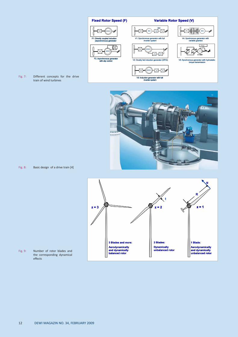
Fig. 9: Number of rotor blades andthe corresponding dynamical effects
12 DEWI MAGAZIN NO. 34, FEBRUARY 2009

gearbox) together with the elastic movement of the bed-plate introduces unknown forces into the bearings of thegearbox and subsequently leads to their overload. Manywind turbines use this basic design with more or less stiff-ness-increasing additional structure components. The resultof this short consideration is that the source of the gearboxfailures should not be searched only inside the gearboxesbut probably could be found in the load-adding inadequatethree-point bearing design.
Two simple solutions are possible: firstly the gearbox manu-facturer provides a gearbox which includes a one- or two-point rotor bearing or secondly the rotor shaft with its one-or two-point bearing support must be connected to thegearbox by a flexible coupling which allows axial and radialdisplacements of the rotor shaft. The message is that cor-rectly designed and mounted gearboxes are able to operate20 years! To change to gearless designs only because of thegearbox problems means to escape from problems whichcan be solved.
5.3 Number of Rotor Blades
Today the industry usually uses three rotor blades in theirwind turbines. One of the reasons is that the dynamicalbehaviour of the rotor during rotation is independent of theazimuth angle or in other words, the inertia moment of therotor related to the tower axis is constant for each rotation-al angle equal to the behaviour of a flat disc plate. With lessthan three rotor blades the rotor changes its inertia momentwith the revolution angle which in consequence leads todynamical movements and therefore to additional loads(Fig. 9). Rotors with less than three rotor blades need tohave higher blade tip speeds to achieve their maximum effi-ciencies, a fact which causes higher noise emissions. On-shore higher noise is not acceptable, but for off-shore windturbines the situation may be different.
With the beginning off-shore application of very large windturbines the question might come up again, if two bladedrotors could be a solution to reduce investment (one bladeless), transportation, assembling and maintenance cost. Inview of the necessity to reduce the additional loads causedby the non-uniform rotational dynamic behaviour of therotor the implementation of a teetering hub for the twobladed rotor probably will become necessary. In that case acareful analysis of the advantages and disadvantages of thetwo-bladed rotor has to be done. The future certainly willshow which technical rotor concepts will have an economicchance to enter the off-shore market.
5.4 Rotor Blade Manufacturing
The manufacturing of rotor blades is still mostly manualwork today. Some production improvements were intro-duced in the last years which shortened the production timeconsiderably, reduced the necessary man power andimproved the reproducibility of the manufacturing quality.The normal production procedure is to manufacture theupper and the lower shell of the rotor blade in separatemoulds and glue them together after the cure procedure.Siemens applies a manufacturing method in which theupper and lower rotor blade shell will be produced in one
piece without bonding (Fig. 10, [5]). The advantage of thismethod is the avoidance of bondings which can lead to ahigher failure probability, the disadvantage seems to be ahigher blade mass.
Today many rotor blade failures are caused by bonding prob-lems. Bondings are necessary not only at the leading andtrailing edge of the blade but also for the fixation of theshear web in between the longitudinal load carrying upperand lower spars. Whereas the shear web will be glued firstunder visual control into one of the two shells, the secondbonding has to be done when closing the two shells or inother words the quality of the bonding cannot be controlledanymore visually. In spite of differing bonding material prop-erties and not correct curing temperature which can pro-voke insufficient bonding quality, also possibly missing bond-ing paste can be followed by mechanically caused failures ofthe blade structure. In principle the question is if the invisi-ble bonding can be chosen in a way that a certain failsafebehaviour can be reached. For the shear web the questionthen would be if the invisible bonding should be done on thetensile or the compression side of the airfoil (Fig. 11).
6. Foundations
Foundations are and can be very different in design onshoreas well as for offshore applications. Whereas onshore differ-ent solutions exist depending on the soil conditions, off-shore foundations are not yet optimised in their basic struc-ture. But also onshore foundations can show some newproblems like cracks in the concrete which appear aftersome time of operation and at least cause an additionaleffort for repair and maintenance. Are these cracks causedby faulty construction or are they the result of structuralmotions due to the increasing elasticity of the very largewind turbines?
Offshore foundation solutions depend on the water depth asshown in principle in Fig. 12. For water depths above 20 mjacket, tripod and tripile solutions are chosen, because themonopile would become too large in diameter. With thetripile solution the advantages of the simpler monopile con-struction and transportation can be used, but the necessaryload distributing structure on top must be designed careful-ly concerning material fatigue due to the possible motions.In the German offshore test site Alpha Ventus jacket(Repower) and tripod (AREWA Multibrid) foundations willbe used whereas in the first commercial wind farm of BardEngineering the tripile solution will be applied. This offersthe chance to compare the behaviour and also the construc-tion, assembling and transportation efforts of the three dif-ferent solutions.
7. Condition Monitoring and Logistics
Wind turbines are machines which have to be maintainedand supervised during their operational life time. Especiallyoffshore the access to the turbines is very strongly depend-ent on the weather conditions. Waves exceeding a certainheight prevent any access by ship, and the more flexible wayto use helicopters is expensive and limits the capacity oftransportation of spare parts. Therefore solutions are neces-sary to monitor the operation of the wind turbines and to
DEWI MAGAZIN NO. 34, FEBRUARY 2009 13

14 DEWI MAGAZIN NO. 34, FEBRUARY 2009
find solutions for a better access to them underunfavourable weather conditions. In principle two types ofcondition monitoring systems exist.
7.1 Failure Condition Monitoring
Today condition monitoring systems are mainly used todetect component failures before they cause additionaldamage in other machinery parts. The monitoring systemsobserve the correct operation by measuring temperatures,vibrations, noise and other signals and give an alarm whenthey are outside of their acceptable ranges. That means thatthey are only used to inform as early as possible aboutupcoming failures, mainly a request by the insurance compa-nies, a consequence of the still numerous gearbox, bearingand structural failures. Therefore condition monitoring sys-tems today are applied to avoid consecutive faults of a firstfault and by this reduce the repair cost. They do not avoidfailures, they only indicate the upcoming malfunction of acomponent at an early stage.
7.2 Operation Condition Monitoring
Compared to the failure condition monitoring, the operationcondition monitoring shall give information about the oper-ational loads already seen. With this information mainte-nance for example can be scheduled earlier or later accord-ing to the operational loads registered. This option is inter-esting especially for offshore operation due to the limitedtimes of access, but also for onshore wind turbines, which
for example in low turbulent wind (flat terrain) could oper-ate longer without maintenance than in high turbulent airstreams (complex terrain). Also the rotor wake inducedloads by turbulences in a wind farm could differ very much ifthe frequency distribution of the wind direction changeswith time. Using this information allows to postpone orbring forward the maintenance. Concerning the life time ofcomponents the information about the loads already seenallows an estimate about the life time already consumed andtherefore for example how long the rotor blades or othercomponents can still be used. Such monitoring systems stillhave to be developed because they must be well adopted tothe needs.
8. Wind Turbine Recycling After Operational Life
The amount of material used in a wind turbine increaseswith the number of wind turbines installed year by year. The2007 world-wide installed capacity of 94,000 MW willincrease to about 700,000 MW in 2017 [3]. Recycling of steeland non-ferrous metals do not create any problems. But therotor blades made of glass, carbon fibres, foams and resinsare waste or at least difficult to recycle (see article page 32of this DEWI Magazin [6]). With a simple calculation therotor blade total weight installed will grow in the next 10years from about 660,000 tons in 2007 to 7,000,000 tons in2017. This rapid increase makes clear that the industry hasto start to develop solutions how to get rid of the waste inecological acceptable recycling or waste treatment proce-dures.
Tensile Spar
Compression Spar
Tensile Spar
Compression Spar
Fig. 10: Rotor blade manufactured in onepiece [5]
Fig. 11: Where to make the blind bondingsfor the shear web and the leadingedge section under consideration ofa fail safe behaviour? At the tensileor the compression side of theblade?

9. Conclusion
The report shows that wind turbines and the their applica-tion still needs many technical improvements. Until now thecompetition between manufacturers was based on a year byyear increase in rotor diameter, which attracted the con-sumers to always buy the bigger wind turbine for their newwind farm projects. This and the rapid world-wide annualgrowth of the market left no time to the manufacturers toimprove the design of their wind turbine. Often the growthin size was based on up-scaling procedures which perhapsdid not take into account sufficiently the changing designconditions with size concerning increasing elasticity of thewind turbines, knowledge of operational conditions, manu-facturing quality and material properties. Consequently thedesign and manufacturing quality of the wind turbines werenot always optimal and caused operational problems.Sometimes one can have the impression that the engineersinvolved in the development of the various parts of a windturbine do not understand one another so that the wind tur-bine is full of interface problems. The aeronautical engineerfor the rotor blades who thinks in elasticity and fatiguestrength, the mechanical engineer who designs againststress limits and the civil engineer who assures the static sta-bility of the structure when designing the foundation of thewind turbine. This consideration underlines that a wind tur-bine is not simply the sum of its assembled components orresearch results, but a product of mutually adjusted compo-nents which take into account the existing operational loadsand motions. Wind turbines are a complex mechanical sys-
tem which needs a complex understanding of the engineersto avoid interface problems in between the different windturbine components.
References:
[1] Molly, J.P.; Wind Energy: Overall Potential and Opportunities. GlobalRenewable Energy Forum, Organized by UNIDO and Ministério deMinas e Energia Brasil, Foz do Iguaçu, Brazil, 18-21 May 2008
[2] Molly, J. P.; Wind Energy – Quo Vadis? 9th German Wind EnergyConference, DEWEK 2008, Bremen, Germany, 26/27 November 2008
[3] BTM Consult; International Wind Energy Development – WorldMarket Update 2007, Forecast 2008-2012; Ed.: BTM Consult ApS,Ringkøping, Denmark, March 2008
[4] Schematic illustration by Bosch Rexroth, www.boschrexroth.com[5] IntegralBlade® by Siemens[6] Albers, H., et. al.; Recycling of wind turbine rotor blades - fact or fic-
tion? DEWI Magazin no. 34, Feb. 2009
DEWI MAGAZIN NO. 34, FEBRUARY 2009 15
Monopile
< 20 m
Gravity Foundation
< 10 mTripod
>20 m
Jacket
>20 m
Tripile
>20 mMonopile
< 20 m
Gravity Foundation
< 10 mTripod
>20 m
Jacket
>20 m
Tripile
>20 mMonopile
< 20 m
Gravity Foundation
< 10 mTripod
>20 m
Jacket
>20 m
Tripile
>20 m
Monopile Jacket Tripod Tripile
GE 3.6 REpower 5M Multibrid M 5000 Bard VM
Monopile Jacket Tripod Tripile
GE 3.6 REpower 5M Multibrid M 5000 Bard VM
Fig. 12: Different offshorefoundation solu-tions according tothe water depth
Fig. 13: Four different offshorefoundation designs forwind turbines of themulti-megawatt size