ug-1041 ecap-9040 user's guide - castle power...
TRANSCRIPT

UG-1041eCAP-9040
User's Guide
April 2006

2
Copyright © 2006 by QEI Inc.UG-1041 eCAP-9040 User's GuideALL RIGHTS RESERVED
NOTICE
The information in this document has been carefully checked and is believed to beaccurate. However, no responsibility is assumed or implied for inaccuracies. Furthermore, QEI, INC., reserves the right to make changes to any products herein describedto improve reliability, function or design. QEI, Inc. does not assume liability arising ourto the application or use of any product or circuit described herein; neither does itconvey any license under its patent rights nor the rights of others.
This manual and all data contained constitutes proprietary information of QEI, Inc. andshall not be reproduced, copied or disclosed to others, or used as the basis formanufacture without written consent of QEI, Inc.
QEI Inc.60 Fadem RoadSpringfield, NJ 07081Phone: (973) 379-7400Fax: (973) 379-2138Web Site: www.qeiinc.com

UG-1041 eCAP-9040 User's Guide
Copyright © 2006 QEI, Inc. Revisions • i
Revisions
Revision Description Date
A Release to Production January 2003
B Corrected Figure 2.4, addedWarnings in section 2.5, CorrectedTypographical Errors Sections 3.2,3.6.4 and 3.5.8
June 2003
C Additional revisions November 2003
D Added information for RadioInterface board and SCADAoverride capability.
September 2005
E Added information for neutralcurrent detection local automaticfunctions.
April 2006

UG-1041 eCAP-9040 User's Guide
Copyright © 2006 QEI, Inc. Contents
Contents
1. Introduction ....................................................................................... 51.1 Definitions ................................................................................61.2 Specifications...........................................................................7
1.2.1 Size...........................................................................71.2.2 Temperature Sensor.................................................71.2.3 Operation Counter....................................................71.2.4 Current Sensor .........................................................71.2.5 Capacitor Switch Relays ...........................................71.2.6 Supply Voltage..........................................................71.2.7 Line Frequency.........................................................71.2.8 Switching Condition (algorithm) Storage ..................71.2.9 RMS Value Measurement.........................................71.2.10 Power Consumption..................................................71.2.11 Historical Data Storage.............................................71.2.12 Environment..............................................................81.2.13 Case .........................................................................81.2.14 Switching Algorithms .................................................81.2.15 Radio/Modem Dimensions ........................................81.2.16 Radio/Modem Power Supply.....................................8
2. Installation.......................................................................................... 92.1 Making Connections.................................................................92.2 Grounding................................................................................92.3 4-Wire System Installation......................................................102.4 3-Wire System Installation......................................................122.5 Line Current Measurement ....................................................142.6 Neutral Current Measurement................................................142.7 Meter Socket Mounting ..........................................................152.8 Pole Mounting ........................................................................162.9 Terminal Strip Mounting .........................................................172.10 Environmental Considerations ...............................................17
3. Operation..........................................................................................183.1 Front Panel Layout ................................................................18
3.1.1 Fuses and Fuseholders..........................................223.1.2 Battery ....................................................................223.1.3 Clock ......................................................................22
3.2 Programming an eCAP for Operation.....................................233.3 Menu Summary ......................................................................243.4 eCAP Setup via Front Panel Switches....................................25
3.4.1 eCAP Menu Interface Switches...............................253.4.2 Menu Description....................................................27
3.5 eCAP Menu Description .........................................................283.5.1 Start-up Banner ......................................................28
eCAP-9040 User's Guide UG-1041
ii • Contents Copyright © 2006 QEI, Inc.
3.5.2 Voltage, Current (Condition Status)........................283.5.3 KW, kVAr, PF (Condition Status)............................283.5.4 Switches Open, Switches Closed (Adjustable) ........293.5.5 Switch Delay Settings (Adjustable)..........................343.5.6 Date and Time (Adjustable) ....................................353.5.7 Config Constants (Adjustable) ................................363.5.8 Operating Mode (Condition Status, Adjustable)......373.5.9 Unit ID (Adjustable).................................................423.5.10 Temperature (Condition Status, Adjustable)...........423.5.11 Switch Status (Condition Status).............................423.5.12 Operations Count ...................................................433.5.13 Switching V-Hyst (Adjustable) .................................43
4. Switching Algorithm Reference Guide .....................................454.1 Introduction ............................................................................46
4.1.1 General Considerations..........................................464.1.2 Operating Parameters ............................................464.1.3 General Information................................................47
4.2 Common Switching Algorithms ...............................................514.2.1 Temperature Control Switching (Example #1).........514.2.2 Temperature Control Switching (Example #2).........514.2.3 Time & Date Control ...............................................524.2.4 Time of Day Switching.............................................524.2.5 Day of Week Switching...........................................534.2.6 Voltage Control.......................................................534.2.7 VAR Control............................................................544.2.8 VAR Control with Voltage Override .........................544.2.9 Power Factor Switching...........................................554.2.10 Current Switching....................................................55
4.3 Customized Switching Algorithms ...........................................564.3.1 Switching Algorithm Evaluation Process..................564.3.2 Switching Algorithm Development Considerations...57
5. SmartWare........................................................................................585.1 Running "SmartWare" ............................................................595.2 Main Menu .............................................................................61
5.2.1 File Menu................................................................615.2.2 Comms Menu..........................................................625.2.3 Setup Menu ............................................................625.2.4 SmartTrends Menu.................................................635.2.5 SmartView Menu.....................................................635.2.6 SmartSim ................................................................635.2.7 Help ........................................................................63
5.3 Bottom Line Parameters.........................................................645.4 View Template Window (Configuration Overview Window) .....645.5 Read from/Send to Cap Control Window................................655.6 Setup Fame ...........................................................................665.7 SmartWare Setup Window .....................................................67
5.7.1 Deleting an Entry ....................................................685.7.2 Modifying an Entry..................................................68
5.8 Hardware Configuration Window............................................695.8.1 Voltage Constants Frame .......................................695.8.2 Power Direction Frame ...........................................705.8.3 Switching Delta-V Frame.........................................70
UG-1041 eCAP-9040 User's Guide
Copyright © 2006 QEI, Inc. Contents
5.8.4 Current Sensing Frames.........................................715.8.5 Read/Send/Exit Buttons ..........................................72
5.9 Timing Parameters Window....................................................735.9.1 Transient Condition Delays Frame .........................735.9.2 Switch Operation Timing Frame ..............................735.9.3 Capacitor Discharge Inhibit Frame .........................735.9.4 Anti-Oscillation Inhibit Frame ..................................745.9.5 Inside Temperature Calculation Frame...................74
5.10 Holidays Window....................................................................755.10.1 Holidays List ...........................................................76
5.11 Neutral (Neutral Current Detection).......................................775.12 Identification Window..............................................................80
5.12.1 Unit Id Number........................................................805.13 SmartMemo............................................................................805.14 Temperature Units .................................................................805.15 Calibration..............................................................................815.16 Reset .....................................................................................815.17 SmartView Window.................................................................82
5.17.1 Electrical Conditions Frame ....................................825.17.2 Date-Time Frame....................................................835.17.3 SmartMemo Frame .................................................835.17.4 Control Parameters Frame .....................................84
5.18 Operating Procedures............................................................855.19 Additional Help .......................................................................85
6. SCADA Communications.............................................................866.1 Installing a Radio....................................................................86
6.1.1 Universal Radio Mounting Plate..............................876.2 Radio Power Supply...............................................................876.3 RS-232 Port Connections ......................................................886.4 RS-232 Cables.......................................................................896.5 Communications Board ..........................................................91
6.5.1 Jumpers - Factory Configuration ............................916.5.2 TX / RX LEDs.........................................................926.5.3 Setting the Baud Rate.............................................93
6.6 Radio Interface Board ............................................................936.6.1 DB9 RS-232 Cable: ................................................956.6.2 DB25 RS-232 Cable: ..............................................96
6.7 Antenna .................................................................................966.8 Local/Remote Front Panel Switch ..........................................97
7. SCADA Override (optional) ..........................................................977.1 Introduction ............................................................................977.2 Relevant DNP Points..............................................................997.3 Algorithm Programming Considerations ...............................100
7.3.1 “VCor” and “Learn Mode” .....................................1007.4 Algorithms ............................................................................101
7.4.1 Example #1 ...........................................................1017.4.2 Example #2 : .........................................................102
8. DNP3 Device Profile w/Point List .............................................104
9. CAP-9040 Communications Upgrade Kit...............................1209.1 Preparation ..........................................................................1209.2 Power Supply Installation .....................................................121

eCAP-9040 User's Guide UG-1041
iv • Contents Copyright © 2006 QEI, Inc.
9.3 SCADA Comm. & Radio Interface Board Installation ............123
UG-1041 eCAP-9040 User's Guide
Copyright © 2006 QEI, Inc. Introductionl 5
1. IntroductionThe eCAP-9040 is part of QEI’s family of Capacitor Bank Controllers. Although it stillperforms the same functions as the QEI “MiniCap” and “MicroCap”, the eCAP adds aSCADA communications port, and can support a variety of communications hardware(data radios, modems, etc.). Communications equipment may be mounted inside theeCAP enclosure, which saves on installation costs. All analog, status, and control pointsare remotely accessible via DNP3 communications protocol. Other protocols areavailable.
Like the MCAP family, the eCAP is designed to monitor any combination of AC voltage,current, watts, vars, power factor, time, date, day-of-week, holiday, or temperature. eCAP will automatically switch a capacitor bank in to or out of the circuit depending onthe conditions observed. (Note: current, watts, vars, phase angle, and power factormonitoring require a customer-supplied Line Post Current Sensor or CurrentTransformer. The sensor is not required for voltage, time/date/day-of-week/holiday, ortemperature monitoring.) There is no need to buy or inventory separate units based onmonitoring requirements. One eCAP unit does it all.
eCAP makes switching decisions by measuring or calculating values such as voltage,current, watts, vars, power factor, time-of-day, day-of-week, date, holiday, temperature,etc. (eCAP contains a battery-backed time of day clock/calendar and a temperaturesensor as standard equipment.) Monitored (or calculated) values are then comparedagainst a list of user configured switching conditions (algorithms) that are set in thecontroller. A list of up to 10 switching conditions for each Cap Bank switch position(OPEN or CLOSED) can be created.
The eCAP keeps historical information in non-volatile memory. It maintains anoperations log and a history of the measurements taken of the monitored circuit. Themeasurement history is optionally saved as 1, 2, 5, or 15 minute averages. Enoughinformation is saved so that a complete operating history is available.
eCAP can be set up and operated via a serial link to a typical laptop computer (or otherPC), running QEI=s ASmartWare@ program This program is also used to retrieve andexamine the historical data stored by the controls. The program allows the data frommultiple controls to be saved and viewed.
The eCAP front panel has an AAuto/Manual@ switch and an AOpen/Close@ switch. ThreeLED indicators are included. A yellow LED indicates Auto Mode (LED is on or blinking)or Manual Mode (LED is off). A red LED indicates that the Cap Bank is CLOSED (redLED is on), or a CLOSE operation is pending (red LED is blinking). A green LEDindicates that the Cap Bank is OPEN (green LED is on), or an OPEN operation ispending (green LED is blinking).
A panel mounted 9 pin female RS232 connector allows the eCAP to be connected to alaptop (or any PC with a standard 9-pin serial port) using a standard one-to-one 9-pinserial port cable. A switch labeled “Remote/Local” is used to place the eCAP undercontrol of a laptop PC (Local) or under SCADA control via DNP3 throughcommunications hardware (Remote). Two red LEDs indicate data transmit/receive(Tx/Rx) when the switch is in the “Remote” state.

eCAP-9040 User's Guide UG-1041
6 lIntroduction Copyright © 2006 QEI, Inc.
Special QEI SmartWare software, installed on a laptop (or other) computer, is used forediting all of the configuration settings, as well as for historical data retrieval. eCAPconfiguration settings are also accessible remotely via SCADA communications, orlocally via front panel switches and LCD display.
Internal timers and logic in the eCAP protect user and equipment from undesired andnon-secure operations. Using timers and logic, the controls can prevent unsafeoperations. Internal timers also allow the user to initiate local operations and leave thevicinity of the control before the switching operation occurs.
Latest new features in the QEI eCAP-9040 include local voltage override capability forSCADA, and expanded neutral current detection features that provide local automaticfunctions.
1.1 Definitions
Below is a list of special terms that are used throughout this user=s guide:
• Switching Algorithms. The internal control schemes that the controller usesto determine whether to switch the cap bank opened or closed. These controlschemes are programmed into the controller by the user, through the eCAPfront panel switches or using QEI’s SmartWare software to enter them into thecontroller via its front panel RS-232 port.
• SmartWare. This is a PC based program that is used to setup, operate, andinterrogate the eCAP.
• Window. A window is the display element that is used to transmit information tothe operator / user. It is a rectangular area of the screen with border around it.It has a top line with a title and may have a bottom line separated into individualcommunication areas called Panels.
• Frame. A frame is a subsection of a window. Frames normally contain groupsof information that are logically related.
• Panel. A panel is an optional area at the bottom of a window that is containsinformation relating to the entire window. The bottom line may contain severalpanels.
• Data Entry Box. When a box like the one shown appears, the user can enter avalue into the box. The number entered becomes the value of the parameter.
• Selection Window. When a data entry box like the one shown is present, thisindicates that there are a number of fixed selections that the user can makeusing the box. By selecting the arrow, the list of available selections is shown. Ifthe user clicks on one of the selections, it becomes the value of the box.
UG-1041 eCAP-9040 User's Guide
Copyright © 2006 QEI, Inc. Introductionl 7
1.2 Specifications
1.2.1 Size
Height 12", Width 10", Depth 7.5"
1.2.2 Temperature Sensor
0E to 140EF (-15E to 60EC)
1.2.3 Operation Counter
Internal software counter and optional electro-mechanical counter
1.2.4 Current Sensor
Line Post Sensor or a Current Transformer (neither are included with the control)
1.2.5 Capacitor Switch Relays
Electro-mechanical relays rated at 20 amps continuous duty at 240 VAC.
1.2.6 Supply Voltage
120 VAC or 240VAC. The supply voltage is also used to sense the line voltage.
1.2.7 Line Frequency
50 Hz or 60 Hz
1.2.8 Switching Condition (algorithm) Storage
10 Close steps and 10 Open steps
1.2.9 RMS Value Measurement
True RMS values are calculated through rapid and simultaneous voltage and currentsampling.
1.2.10 Power Consumption
2 VA, not including communications transceivers (data radio, modem etc.).
1.2.11 Historical Data Storage
The average of all electrical parameters is saved on a 1-minute interval (13 days), 2-minute interval (26 days), 5-minute interval (65 days), or 15-minute interval (196 days).

eCAP-9040 User's Guide UG-1041
8 lIntroduction Copyright © 2006 QEI, Inc.
1.2.12 Environment
-40EF to 149EF (-40EC to 65EC) Temperature; 95% Humidity (non-condensing)
1.2.13 Case
NEMA 4 rated, weatherproof outdoor type.
1.2.14 Switching Algorithms
Capacitor bank is switched on any combination of the following parameters: Voltage,Current, VARs, Watts, Power Factor, Temperature, Time, Date, Day-of-Week, Holiday.
1.2.15 Radio/Modem Dimensions
Height 7” max. X Width 6” max. X Depth 1.5” max. Radio and antenna are not suppliedby QEI. The customer can choose.
1.2.16 Radio/Modem Power Supply
A power supply is included in the eCAP, and can be used to provide power for a radioor a modem.
Input: 90-264VAC 50/60Hz.
Output: +12Vdc @ 2.5 Amps.
UG-1041 eCAP-9040 User's Guide
Copyright © 2006 QEI, Inc. Installationl 9
2. Installation
2.1 Making Connections
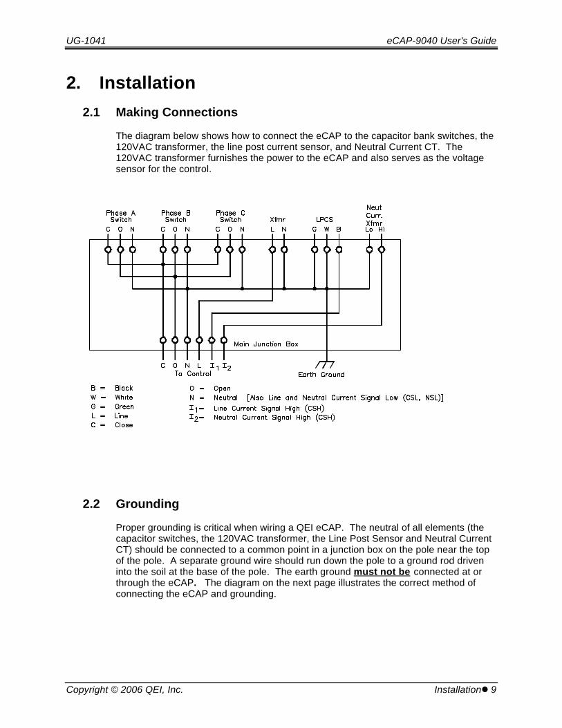
The diagram below shows how to connect the eCAP to the capacitor bank switches, the120VAC transformer, the line post current sensor, and Neutral Current CT. The120VAC transformer furnishes the power to the eCAP and also serves as the voltagesensor for the control.
2.2 Grounding
Proper grounding is critical when wiring a QEI eCAP. The neutral of all elements (thecapacitor switches, the 120VAC transformer, the Line Post Sensor and Neutral CurrentCT) should be connected to a common point in a junction box on the pole near the topof the pole. A separate ground wire should run down the pole to a ground rod driveninto the soil at the base of the pole. The earth ground must not be connected at orthrough the eCAP. The diagram on the next page illustrates the correct method ofconnecting the eCAP and grounding.
eCAP-9040 User's Guide UG-1041
10 lInstallation Copyright © 2006 QEI, Inc.
2.3 4-Wire System Installation
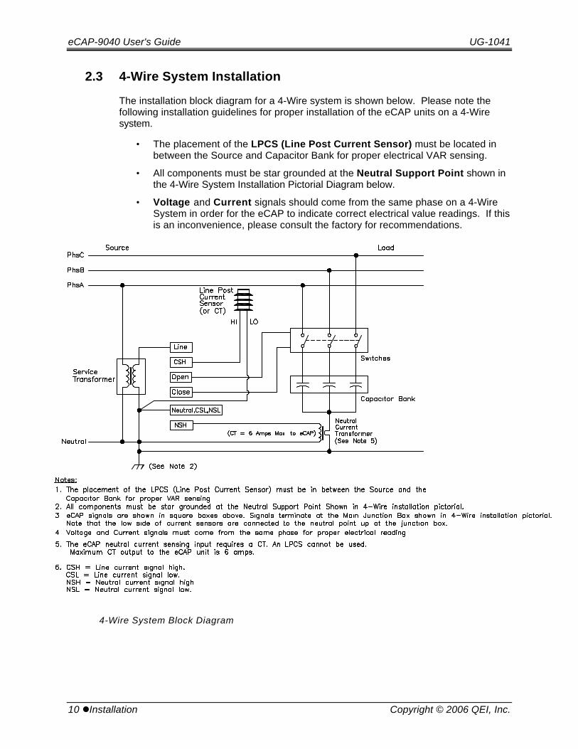
The installation block diagram for a 4-Wire system is shown below. Please note thefollowing installation guidelines for proper installation of the eCAP units on a 4-Wiresystem.
• The placement of the LPCS (Line Post Current Sensor) must be located inbetween the Source and Capacitor Bank for proper electrical VAR sensing.
• All components must be star grounded at the Neutral Support Point shown inthe 4-Wire System Installation Pictorial Diagram below.
• Voltage and Current signals should come from the same phase on a 4-WireSystem in order for the eCAP to indicate correct electrical value readings. If thisis an inconvenience, please consult the factory for recommendations.
4-Wire System Block Diagram

UG-1041 eCAP-9040 User's Guide
Copyright © 2006 QEI, Inc. Installationl 11
4-Wire Installation Pictorial

eCAP-9040 User's Guide UG-1041
12 lInstallation Copyright © 2006 QEI, Inc.
2.4 3-Wire System Installation
The installation block diagram for a 3-Wire system is shown below. Please note thefollowing installation guidelines for the eCAP units on a 3-Wire system.
• The placement of the LPCS (Line Post Current Sensor) should be located inbetween the Source and Capacitor Bank for proper electrical VAR sensing.
• It is recommended that the customer place the LPCS on the untapped phase.This LPCS setup allows the customer to use a known phase shift (90o) of thecurrent and voltage signals without knowledge of the rotation of the system. The customer may use either of the tapped phases if the rotation of the systemis known. This will only apply to customers using current sensors.
For example, if supply voltage on the control were applied from A Phase and BPhase, the customer would place the LPCS on the C Phase.
3-Wire System Block Diagram

UG-1041 eCAP-9040 User's Guide
Copyright © 2006 QEI, Inc. Installationl 13
3-Wire Installation Pictorial
eCAP-9040 User's Guide UG-1041
14 lInstallation Copyright © 2006 QEI, Inc.
2.5 Line Current Measurement
A Fisher-Pierce Series 1301 LPCS, 1701 LPCS or Lindsey 9600 Series LPCS with a600 amp: 10-volt output, or a 5-amp CT secondary are used to sense line current. Theoutput from this device is monitored directly by the eCAP control unit.
NOTE: Please indicate whether the sensor is a true CT or a current-to-voltage type sensor whenordering. Some manufacturers manufacture both true CT sensors and current-to-voltage sensors. It is absolutely necessary that the customer indicate which one will be used. Using a differentsensor than what is specified for our controls may cause damage to the unit.
WARNING: Do not connect a CT to a unit labeled with a LPCS (Line Post CurrentSensor) Only Sticker. Also, a LPCS cannot be connected to a unit with a CT onlysticker. Failure to follow the unit’s markings may result in unit damage.
WARNING: When disconnecting CT’s, make certain that all shorting procedures arefollowed prior to disconnection. Failure to follow this may result in damage to the unitand/or personal injury or death.
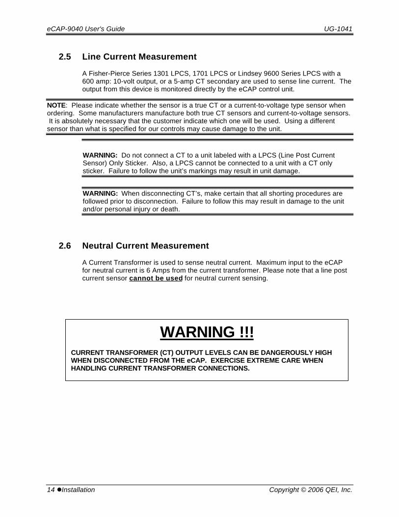
2.6 Neutral Current Measurement
A Current Transformer is used to sense neutral current. Maximum input to the eCAPfor neutral current is 6 Amps from the current transformer. Please note that a line postcurrent sensor cannot be used for neutral current sensing.
WARNING !!!CURRENT TRANSFORMER (CT) OUTPUT LEVELS CAN BE DANGEROUSLY HIGHWHEN DISCONNECTED FROM THE eCAP. EXERCISE EXTREME CARE WHENHANDLING CURRENT TRANSFORMER CONNECTIONS.

UG-1041 eCAP-9040 User's Guide
Copyright © 2006 QEI, Inc. Installationl 15
2.7 Meter Socket Mounting
Meter Socket mounted units are available in 5 socket configurations as shown in thefigure below. Inspect the eCAP unit and verify that the unit matches the availablesocket. Consulting the sticker on the inside of the unit cover does this. (The viewsbelow are looking into the meter socket.)
Units are secured in place with a lock collar to prevent the eCAP from being removedfrom its socket by unauthorized personnel.
WARNING !!!CURRENT TRANSFORMER (CT) OUTPUT LEVELS CAN BE DANGEROUSLY HIGHWHEN DISCONNECTED FROM THE eCAP. EXERCISE EXTREME CARE WHENHANDLING CURRENT TRANSFORMER CONNECTIONS.
eCAP-9040 User's Guide UG-1041
16 lInstallation Copyright © 2006 QEI, Inc.
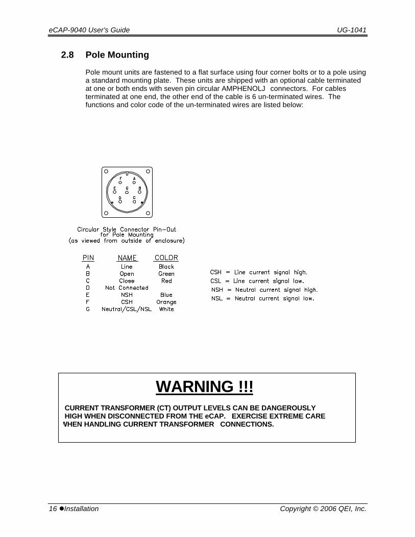
2.8 Pole Mounting
Pole mount units are fastened to a flat surface using four corner bolts or to a pole usinga standard mounting plate. These units are shipped with an optional cable terminatedat one or both ends with seven pin circular AMPHENOLJ connectors. For cablesterminated at one end, the other end of the cable is 6 un-terminated wires. Thefunctions and color code of the un-terminated wires are listed below:
WARNING !!! CURRENT TRANSFORMER (CT) OUTPUT LEVELS CAN BE DANGEROUSLY HIGH WHEN DISCONNECTED FROM THE eCAP. EXERCISE EXTREME CARE WHEN HANDLING CURRENT TRANSFORMER CONNECTIONS.
UG-1041 eCAP-9040 User's Guide
Copyright © 2006 QEI, Inc. Installationl 17
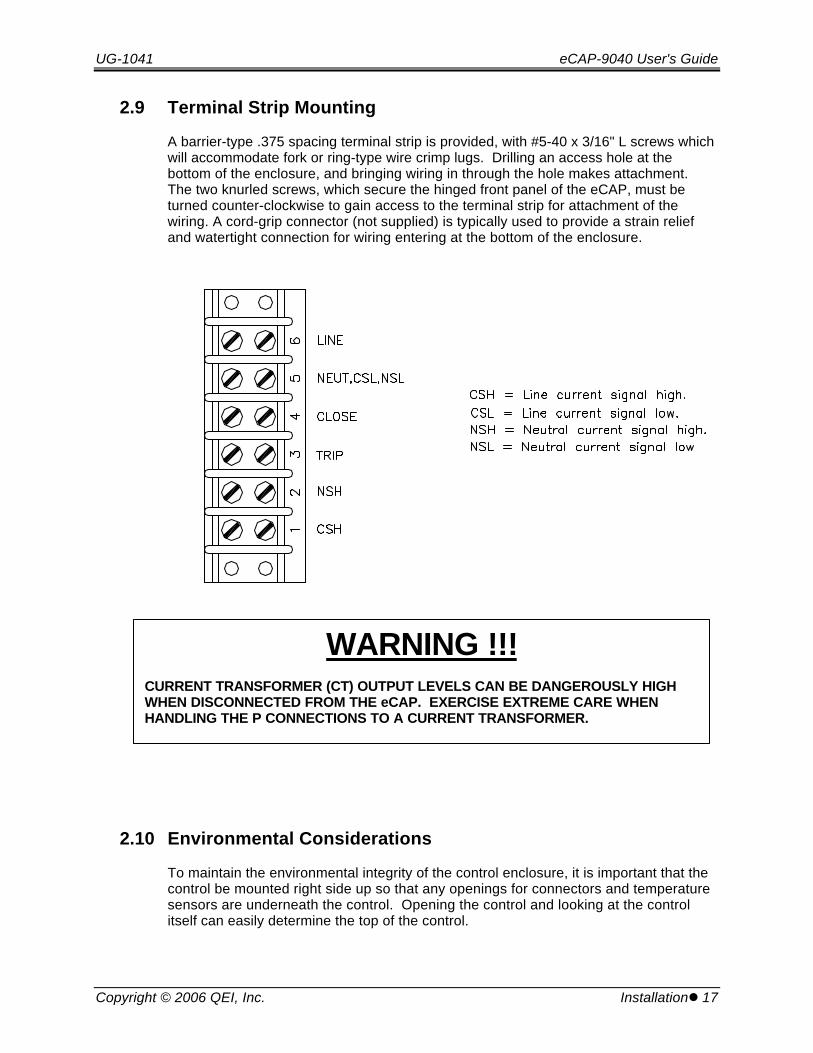
2.9 Terminal Strip Mounting
A barrier-type .375 spacing terminal strip is provided, with #5-40 x 3/16" L screws whichwill accommodate fork or ring-type wire crimp lugs. Drilling an access hole at thebottom of the enclosure, and bringing wiring in through the hole makes attachment. The two knurled screws, which secure the hinged front panel of the eCAP, must beturned counter-clockwise to gain access to the terminal strip for attachment of thewiring. A cord-grip connector (not supplied) is typically used to provide a strain reliefand watertight connection for wiring entering at the bottom of the enclosure.
2.10 Environmental Considerations
To maintain the environmental integrity of the control enclosure, it is important that thecontrol be mounted right side up so that any openings for connectors and temperaturesensors are underneath the control. Opening the control and looking at the controlitself can easily determine the top of the control.
WARNING !!!CURRENT TRANSFORMER (CT) OUTPUT LEVELS CAN BE DANGEROUSLY HIGHWHEN DISCONNECTED FROM THE eCAP. EXERCISE EXTREME CARE WHENHANDLING THE P CONNECTIONS TO A CURRENT TRANSFORMER.

eCAP-9040 User's Guide UG-1041
18 lOperation Copyright © 2006 QEI, Inc.
3. Operation
3.1 Front Panel Layout
The following two pages show the location of all front panel switches, indicators, andcontrols. A description of each item appears on the following pages.
Front Panel Layout Pictorial
UG-1041 eCAP-9040 User's Guide
Copyright © 2006 QEI, Inc. Operationl 19
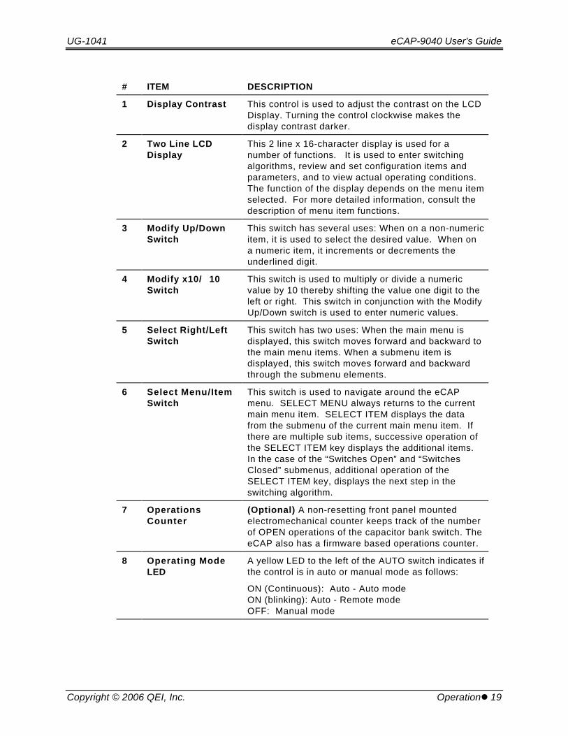
# ITEM DESCRIPTION
1 Display Contrast This control is used to adjust the contrast on the LCDDisplay. Turning the control clockwise makes thedisplay contrast darker.
2 Two Line LCDDisplay
This 2 line x 16-character display is used for anumber of functions. It is used to enter switchingalgorithms, review and set configuration items andparameters, and to view actual operating conditions.The function of the display depends on the menu itemselected. For more detailed information, consult thedescription of menu item functions.
3 Modify Up/DownSwitch
This switch has several uses: When on a non-numericitem, it is used to select the desired value. When ona numeric item, it increments or decrements theunderlined digit.
4 Modify x10/�10Switch
This switch is used to multiply or divide a numericvalue by 10 thereby shifting the value one digit to theleft or right. This switch in conjunction with the ModifyUp/Down switch is used to enter numeric values.
5 Select Right/LeftSwitch
This switch has two uses: When the main menu isdisplayed, this switch moves forward and backward tothe main menu items. When a submenu item isdisplayed, this switch moves forward and backwardthrough the submenu elements.
6 Select Menu/ItemSwitch
This switch is used to navigate around the eCAPmenu. SELECT MENU always returns to the currentmain menu item. SELECT ITEM displays the datafrom the submenu of the current main menu item. Ifthere are multiple sub items, successive operation ofthe SELECT ITEM key displays the additional items. In the case of the “Switches Open” and “SwitchesClosed” submenus, additional operation of theSELECT ITEM key, displays the next step in theswitching algorithm.
7 OperationsCounter
(Optional) A non-resetting front panel mountedelectromechanical counter keeps track of the numberof OPEN operations of the capacitor bank switch. TheeCAP also has a firmware based operations counter.
8 Operating ModeLED
A yellow LED to the left of the AUTO switch indicates ifthe control is in auto or manual mode as follows:
ON (Continuous): Auto - Auto modeON (blinking): Auto - Remote modeOFF: Manual mode
eCAP-9040 User's Guide UG-1041
20 lOperation Copyright © 2006 QEI, Inc.
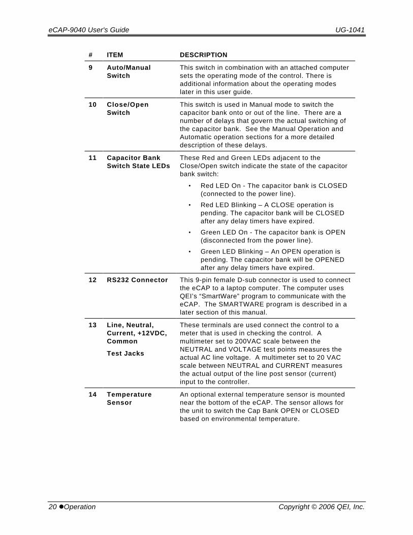
# ITEM DESCRIPTION
9 Auto/ManualSwitch
This switch in combination with an attached computersets the operating mode of the control. There isadditional information about the operating modeslater in this user guide.
10 Close/OpenSwitch
This switch is used in Manual mode to switch thecapacitor bank onto or out of the line. There are anumber of delays that govern the actual switching ofthe capacitor bank. See the Manual Operation andAutomatic operation sections for a more detaileddescription of these delays.
11 Capacitor BankSwitch State LEDs
These Red and Green LEDs adjacent to theClose/Open switch indicate the state of the capacitorbank switch:
• Red LED On - The capacitor bank is CLOSED(connected to the power line).
• Red LED Blinking – A CLOSE operation ispending. The capacitor bank will be CLOSEDafter any delay timers have expired.
• Green LED On - The capacitor bank is OPEN(disconnected from the power line).
• Green LED Blinking – An OPEN operation ispending. The capacitor bank will be OPENEDafter any delay timers have expired.
12 RS232 Connector This 9-pin female D-sub connector is used to connectthe eCAP to a laptop computer. The computer usesQEI’s “SmartWare” program to communicate with theeCAP. The SMARTWARE program is described in alater section of this manual.
13 Line, Neutral,Current, +12VDC,Common
Test Jacks
These terminals are used connect the control to ameter that is used in checking the control. Amultimeter set to 200VAC scale between theNEUTRAL and VOLTAGE test points measures theactual AC line voltage. A multimeter set to 20 VACscale between NEUTRAL and CURRENT measuresthe actual output of the line post sensor (current)input to the controller.
14 TemperatureSensor
An optional external temperature sensor is mountednear the bottom of the eCAP. The sensor allows forthe unit to switch the Cap Bank OPEN or CLOSEDbased on environmental temperature.
UG-1041 eCAP-9040 User's Guide
Copyright © 2006 QEI, Inc. Operationl 21
# ITEM DESCRIPTION
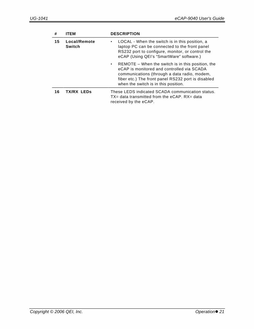
15 Local/RemoteSwitch
• LOCAL - When the switch is in this position, alaptop PC can be connected to the front panelRS232 port to configure, monitor, or control theeCAP (Using QEI’s “SmartWare” software.)
• REMOTE – When the switch is in this position, theeCAP is monitored and controlled via SCADAcommunications (through a data radio, modem,fiber etc.) The front panel RS232 port is disabledwhen the switch is in this position.
16 TX/RX LEDs These LEDS indicated SCADA communication status.TX= data transmitted from the eCAP. RX= datareceived by the eCAP.
eCAP-9040 User's Guide UG-1041
22 lOperation Copyright © 2006 QEI, Inc.
3.1.1 Fuses and Fuseholders
There are three fuses associated with the eCAP. A 10 Amp AGC type 1-1/4 inchcylinder fuse (QEI No. 10-003669-039) is located in the front panel fuseholder (item 17in the front panel pictorial). Another fuse is a ¼ Amp 5 x 20mm slo-blo type fuse (QEINo. 10-003669-044, Littlefuse 218.250) on the lower (larger) printed circuit boardlocated underneath the front panel. If the control were inoperative, one of the firststeps would be to verify that either of these fuses is not blown. A third fuse is a 2 Amp 5x 20mm located on AC input of the internal +12VDC radio power supply. Both of the 5 x20mm fuses are accessed by opening the hinged front panel of the eCAP.
3.1.2 Battery
Each of the two eCAP circuit boards has a +3 VDC lithium battery installed. Thebatteries maintain the clock, and trending (historical data) memory, when power isremoved from the eCAP. The circuit boards are accessed by opening the hinged frontpanel of the eCAP, so that the rear of the front panel is viewed. On the lower (larger)circuit board , there is one battery labeled B1, and it is installed in the upper left cornerof the board. The second battery is located on the upper (smaller) printed circuit board.This battery is labeled BH1 and is located in the upper right corner. The maximum lifeexpectancy of the lithiums in-circuit is 4 years. Customer may request for replacementfrom the factory. Do not substitute with different model number. Themanufacturer and model of the batteries is indicated below.
Manufacturer: RenataModel Number: CR1225
3.1.3 Clock
The eCAP has an internal clock for time keeping when switching is based on Date,Time , or DOW (day of the week). Another function of the clock is as a reference tokeep track of trending (historical) data.
The eCAP’s internal clock has been tested and passed for Year 2000 compliance andwill adjust for Leap Years. The internal clock will not adjust for Daylight Savingstime.
The clock is kept running at all times by the lower internal 3 VDC lithium battery.
UG-1041 eCAP-9040 User's Guide
Copyright © 2006 QEI, Inc. Operationl 23
3.2 Programming an eCAP for Operation
Before being placed into service, the eCAP must be configured.
The eCAP has a front panel RS-232 port, which can be connected to a laptop PC (withQEI’s “SmartWare” software installed and running on the PC) for configuration of alloperating parameters (see the “SmartWare” software section of this user guide.)
Additionally, the eCAP has a Hardware Interface , which is a set of four toggleswitches and an LCD Display. The Hardware Interface can be used to set up many ofthe operating parameters directly from the front panel, without the use of a computer.This may allow for easier set up in the field.
The following MENU SUMMARY table contains a listing of all eCAP Hardware InterfaceMenus and sub-Menus. Information about each item can be found in the OPERATIONsection of this guide, under “eCAP MENU DESCRIPTION”.

eCAP-9040 User's Guide UG-1041
24 lOperation Copyright © 2006 QEI, Inc.
3.3 Menu Summary
Menu Item Submenu Item Format Comments
eCAP vXXX-XXLLPS 0 - 270 Amps
Startup Banner, appears atpower up.
Switches Open Open[0] T FVCor < 120.5 O C
Successive steps selected byoperating the “SELECT ITEM”
switch.
Switches Close Close[0] T FVolt < 120.5 O C
Successive steps selected byoperating the “SELECT ITEM”
switch.
Switch Delays Delay Close OpenSec 10 10
Used to view and alter theseparameters
Date Date Yr Mo Dais 01 01 12
Used to view and set the date
Time Time Hr Mn Wkis 22 45 3
Used to view and set the time
Config Constants Volts Amps Deg7200 60 0
Displays configurationconstants that are set through
“Smartware”
Operating Mode Comm LocalAuto Manual
Status only
Unit ID Unit ID Number1342
Used to view and set thisparameter
Temperature Amb Indoor Lag77 73 30
See the text for a completedescription
Switch Status Status PendingClose Open
Status only
Operations Count Operations Count321
Used to view and set thisparameter
Switching V-Hyst Learn ClsV OpnVYes 2.6 2.0
Used to view and set theseparameters
Voltage, Current Volts VCor Amps122.4 120.4 73
Status only
kW, kVAr, PF kWatt kVAr PF3156 -327 93
Status only

UG-1041 eCAP-9040 User's Guide
Copyright © 2006 QEI, Inc. Operationl 25
3.4 eCAP Setup via Front Panel Switches
The eCAP front panel menu interface consists of 4 control toggle switches, 2 operatingmode-related switches and an LCD display. The control toggle switches are shownbelow. Each control switch is divided in one of two groups: Select and Modify.
3.4.1 eCAP Menu Interface Switches
Selecting
• The Select group includes the controls used to traverse the menus on the LCDdisplay. The MENU/ITEM and RIGHT/LEFT toggle switches are classified underthis group. A Flow Diagram of all the possible menu options is shown on thenext page.
• Selecting the MENU of the MENU/ITEM switch returns the display to the presentmenu option.
• Selecting the ITEM of the MENU/ITEM switch enters the menu item field displayof the LCD.
• RIGHT rotates through all the menu options in one direction. It will also move acursor when available to the right by one.
• LEFT rotates through all the menu options in the opposite direction of RIGHTtoggle switch. It will also move the cursor when available to the left by one.

eCAP-9040 User's Guide UG-1041
26 lOperation Copyright © 2006 QEI, Inc.
Modifying
• The MODIFY group includes the controls used to alter the field conditions of themenu items indicated on the LCD display. The UP/DOWN and ×10/÷10 toggleswitches are under this group.
• Selecting UP of the UP/DOWN switch increments the adjustable field conditionsup by one.
• Selecting DOWN of the UP/DOWN switch increments the adjustable fieldconditions down by one.
• ×10 (Multiplier 10) multiplies the numeric value indicated above the cursor by 10or 1 decimal place to the right.
• ÷10 (Divider 10) divides the numeric value above the cursor by 10 or 1 decimalplace to the left.
NOTES*Both the UP/DOWN and ×× 10/÷÷ 10 only affect adjustable field conditions.*The ×10/÷10 only affects numeric field conditions.
Along with the 4 control toggle switches listed on the previous page, the eCAP alsoincludes 2 more mode-related switches located at the bottom left side of the front panel. The first, labeled Auto/Manual, sets the capacitor to the switching mode desired by theuser. The second switch, labeled Open/Close, opens or closes the capacitors underonly Manual Mode.
UG-1041 eCAP-9040 User's Guide
Copyright © 2006 QEI, Inc. Operationl 27
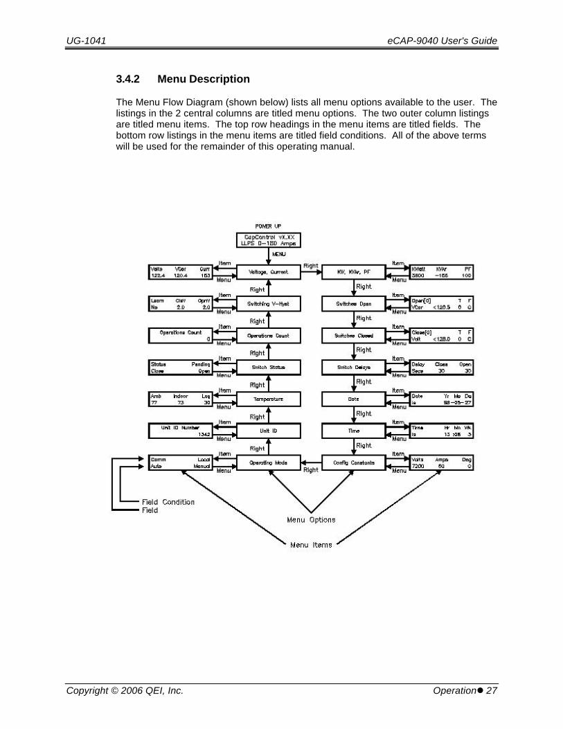
3.4.2 Menu Description
The Menu Flow Diagram (shown below) lists all menu options available to the user. Thelistings in the 2 central columns are titled menu options. The two outer column listingsare titled menu items. The top row headings in the menu items are titled fields. Thebottom row listings in the menu items are titled field conditions. All of the above termswill be used for the remainder of this operating manual.

eCAP-9040 User's Guide UG-1041
28 lOperation Copyright © 2006 QEI, Inc.
3.5 eCAP Menu Description
What follows is a description of all menus and sub-menu items that can be accessed viathe eCAP Menu. For the following sections, the menu options and their associateditems require the user to be familiar with a few terms. Menu options are categorized aseither a Condition Status or Adjustable.
• Condition Status. The LCD Display conveys information from the controller.
• Adjustable. The LCD Display indicates the present settings of the controllerand will also allow the user to change the settings manually through thehardware interface switches.
3.5.1 Start-up Banner
This starting menu item is displayed when the unit first starts and whenever theswitches have been idle for some time. It identifies the unit as an eCAP, firmwareversion, the current sensor (LLPS - Lindsey Line Post Sensor, FLPS - Fischer-PierceLine Post Sensor, CT - Current Transformer), and the range of the current sensor.
eCAP vXXX-XXLLPS 0 - 270 Amps
3.5.2 Voltage, Current (Condition Status)
Selecting this item allows the user to monitor the following real-time electricalparameters:
• Voltage. PT level:120VAC Nominal
• VCor (Voltage w/ Correction). Details in section titled Switch V-Hyst
• Current. Single Phase
Shown below is an example of the LCD display under this item:
Volt VCor Cur119.3 120.3 119
3.5.3 KW, kVAr, PF (Condition Status)
This menu option lets the user monitor the following real-time electrical parameters:
• Kilowatts. Single Phase kWatt × 3
• KiloVARs. Single Phase kVAr × 3. ç Negative value (-) equals leading,otherwise lagging
• Power Factor. In percent units.
Shown below is an example of the LCD display in this item:
kWatt kVAr PF 2555 -105 100
UG-1041 eCAP-9040 User's Guide
Copyright © 2006 QEI, Inc. Operationl 29
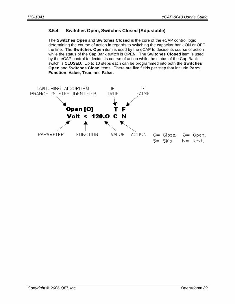
3.5.4 Switches Open, Switches Closed (Adjustable)
The Switches Open and Switches Closed is the core of the eCAP control logicdetermining the course of action in regards to switching the capacitor bank ON or OFFthe line. The Switches Open item is used by the eCAP to decide its course of actionwhile the status of the Cap Bank switch is OPEN. The Switches Closed item is usedby the eCAP control to decide its course of action while the status of the Cap Bankswitch is CLOSED. Up to 10 steps each can be programmed into both the SwitchesOpen and Switches Close items. There are five fields per step that include Parm,Function, Value, True, and False .

eCAP-9040 User's Guide UG-1041
30 lOperation Copyright © 2006 QEI, Inc.
• ParmThis sub-field indicates what parameter status condition to base its decision onfor the present step. The parameters include:
Voltage
Current
kWatts
kVAr
PF (Power Factor)
Temperature
Date
DOW (Day of week)
Time
VCor (Voltage with Correction)
• Function. This sub-field indicates the equality condition against which thecontrol must base the present step decision. This is used in conjunction withthe Value sub-field status condition and the Parm sub-field to form theswitching logic condition for each step. Three functions are allowed in the eCAPalgorithms. These are LESS THAN (<), GREATER THAN (>), and EQUAL TO(=). Only the Date, Time, and DOW parameters are allowed access to theEQUAL TO (=) equality.
• Value. This sub-field is the value against which the Parm is measured and willbe termed the cutoff. All values are to be integer values with exception to theVCor and Voltage. Both VCor and Voltage are allowed one decimal place. Forexample, the customer may user a cutoff value of 124.6 for Voltage or VCor. Below is a description for the correct value entry for each of the parameters.
• Voltage. Secondary voltage value (110.0 to 150.0 volts)
• Current. (+) current value up to the Max Current Limit of the unit (amps)
• VCor. Secondary voltage w/ correction (110.0 to 150.0 volts)
• kWatts. ± integer value, (+) forward, (-) reverse in kWatt units
UG-1041 eCAP-9040 User's Guide
Copyright © 2006 QEI, Inc. Operationl 31
• kVArs. ± integer value, (+) lagging, (-) leading in kVAr units
• PF. ± % integer value (0 to 100), (+) lagging, (-) leading
• Temperature. (+) integer value (0 to 130) in Fahrenheit degree units
• Date. MMDD format (integer value). Example: July 4 = 0704
• Time. HHMM format (integer military time). Example: 12:23 AM = 0023, 1:23PM = 1323
• DOW. (0 to 9)1 = Monday2 = Tuesday3 = Wednesday4 = Thursday5 = Friday6 = Saturday7 = Sunday0, 8, and 9 regarded as special and used in the holiday feature. See“SmartWare” software section.
• True, False. This field indicates the action to take for the present step for theeither the True or False switching logic condition. For example, if a logic stepevaluates true then action indicated under True will be initiated. The 4 actionsare Open, Close, Next, and Skip:
Open indicates a pending OPEN operation.
Close indicates a pending CLOSE operation.
Next indicates the next step condition will be evaluated following thepresent step.
Skip indicates the next step following the present step will be skipped.
eCAP-9040 User's Guide UG-1041
32 lOperation Copyright © 2006 QEI, Inc.
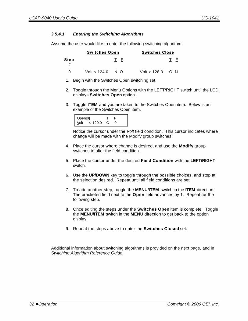
3.5.4.1 Entering the Switching Algorithms
Assume the user would like to enter the following switching algorithm.
Switches Open Switches Close
Step#
T F T F
0 Volt < 124.0 N O Volt > 128.0 O N
1. Begin with the Switches Open switching set.
2. Toggle through the Menu Options with the LEFT/RIGHT switch until the LCDdisplays Switches Open option.
3. Toggle ITEM and you are taken to the Switches Open item. Below is anexample of the Switches Open item.
Open[0] T FVolt < 120.0 C 0
Notice the cursor under the Volt field condition. This cursor indicates wherechange will be made with the Modify group switches.
4. Place the cursor where change is desired, and use the Modify groupswitches to alter the field condition.
5. Place the cursor under the desired Field Condition with the LEFT/RIGHTswitch.
6. Use the UP/DOWN key to toggle through the possible choices, and stop atthe selection desired. Repeat until all field conditions are set.
7. To add another step, toggle the MENU/ITEM switch in the ITEM direction.The bracketed field next to the Open field advances by 1. Repeat for thefollowing step.
8. Once editing the steps under the Switches Open item is complete. Togglethe MENU/ITEM switch in the MENU direction to get back to the optiondisplay.
9. Repeat the steps above to enter the Switches Closed set.
Additional information about switching algorithms is provided on the next page, and inSwitching Algorithm Reference Guide.
UG-1041 eCAP-9040 User's Guide
Copyright © 2006 QEI, Inc. Operationl 33
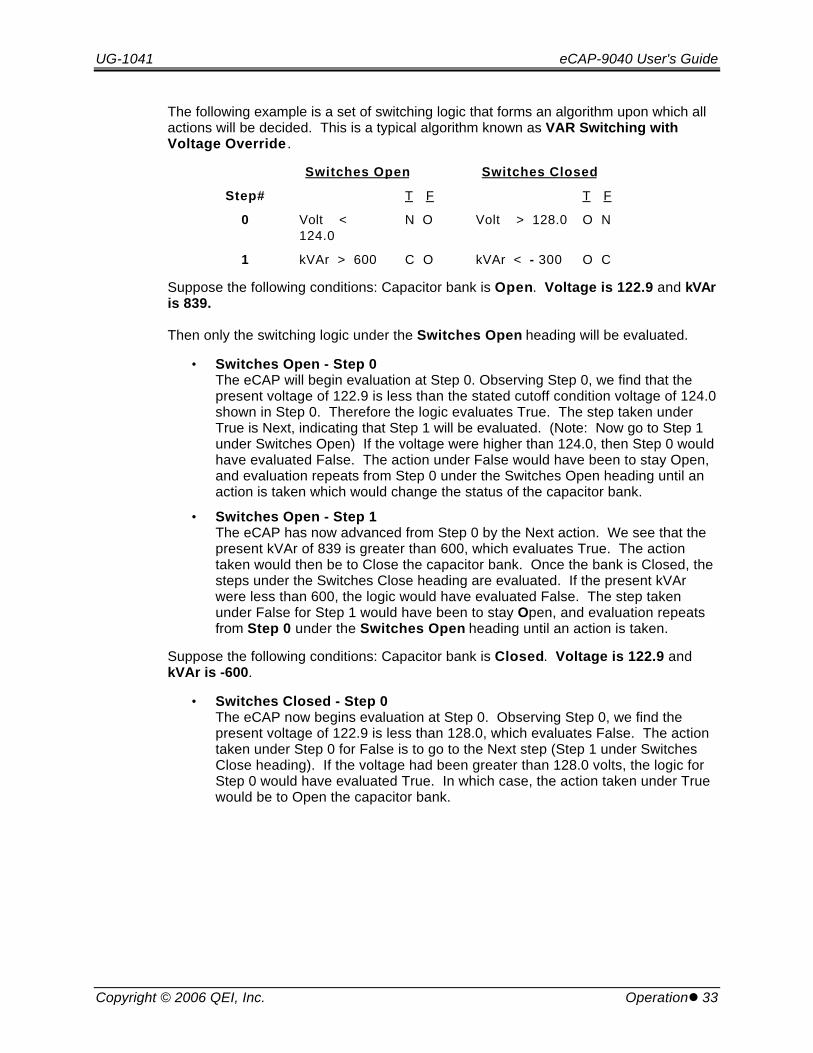
The following example is a set of switching logic that forms an algorithm upon which allactions will be decided. This is a typical algorithm known as VAR Switching withVoltage Override .
Switches Open Switches Closed
Step# T F T F
0 Volt < 124.0
N O Volt > 128.0 O N
1 kVAr > 600 C O kVAr < - 300 O C
Suppose the following conditions: Capacitor bank is Open. Voltage is 122.9 and kVAris 839.
Then only the switching logic under the Switches Open heading will be evaluated.
• Switches Open - Step 0The eCAP will begin evaluation at Step 0. Observing Step 0, we find that thepresent voltage of 122.9 is less than the stated cutoff condition voltage of 124.0shown in Step 0. Therefore the logic evaluates True. The step taken underTrue is Next, indicating that Step 1 will be evaluated. (Note: Now go to Step 1under Switches Open) If the voltage were higher than 124.0, then Step 0 wouldhave evaluated False. The action under False would have been to stay Open,and evaluation repeats from Step 0 under the Switches Open heading until anaction is taken which would change the status of the capacitor bank.
• Switches Open - Step 1The eCAP has now advanced from Step 0 by the Next action. We see that thepresent kVAr of 839 is greater than 600, which evaluates True. The actiontaken would then be to Close the capacitor bank. Once the bank is Closed, thesteps under the Switches Close heading are evaluated. If the present kVArwere less than 600, the logic would have evaluated False. The step takenunder False for Step 1 would have been to stay Open, and evaluation repeatsfrom Step 0 under the Switches Open heading until an action is taken.
Suppose the following conditions: Capacitor bank is Closed. Voltage is 122.9 andkVAr is -600.
• Switches Closed - Step 0The eCAP now begins evaluation at Step 0. Observing Step 0, we find thepresent voltage of 122.9 is less than 128.0, which evaluates False. The actiontaken under Step 0 for False is to go to the Next step (Step 1 under SwitchesClose heading). If the voltage had been greater than 128.0 volts, the logic forStep 0 would have evaluated True. In which case, the action taken under Truewould be to Open the capacitor bank.
eCAP-9040 User's Guide UG-1041
34 lOperation Copyright © 2006 QEI, Inc.
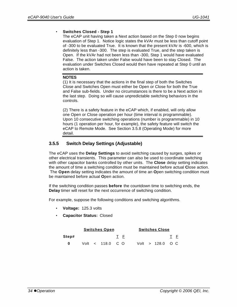
• Switches Closed - Step 1The eCAP unit having taken a Next action based on the Step 0 now beginsevaluation of Step 1. Notice logic states the kVAr must be less than cutoff pointof -300 to be evaluated True. It is known that the present kVAr is -600, which isdefinitely less than -300. The step is evaluated True, and the step taken isOpen. If the kVAr had not been less than -300, Step 1 would have evaluatedFalse. The action taken under False would have been to stay Closed. Theevaluation under Switches Closed would then have repeated at Step 0 until anaction is taken.
NOTES(1) It is necessary that the actions in the final step of both the SwitchesClose and Switches Open must either be Open or Close for both the Trueand False sub-fields. Under no circumstances is there to be a Next action inthe last step. Doing so will cause unpredictable switching behaviors in thecontrols.
(2) There is a safety feature in the eCAP which, if enabled, will only allowone Open or Close operation per hour (time interval is programmable).Upon 10 consecutive switching operations (number is programmable) in 10hours (1 operation per hour, for example), the safety feature will switch theeCAP to Remote Mode. See Section 3.5.8 (Operating Mode) for moredetail.
3.5.5 Switch Delay Settings (Adjustable)
The eCAP uses the Delay Settings to avoid switching caused by surges, spikes orother electrical transients. This parameter can also be used to coordinate switchingwith other capacitor banks controlled by other units. The Close delay setting indicatesthe amount of time a switching condition must be maintained before actual Close action. The Open delay setting indicates the amount of time an Open switching condition mustbe maintained before actual Open action.
If the switching condition passes before the countdown time to switching ends, theDelay timer will reset for the next occurrence of switching condition.
For example, suppose the following conditions and switching algorithms.
• Voltage: 125.3 volts
• Capacitor Status: Closed
Switches Open Switches Close
Step# T F T F
0 Volt < 118.0 C O Volt > 128.0 O C

UG-1041 eCAP-9040 User's Guide
Copyright © 2006 QEI, Inc. Operationl 35
Under the conditions and the switching algorithm shown above, no action should occuras long as the conditions hold steady at their value. Suppose a high voltage transientscause the voltage to be raised above 128.0 volt for a period of 2 seconds. This wouldallow enough time for the control to register a change and attempt to Open even afterthe condition had passed. If the Open Delay setting were set to 10 seconds, this wouldrequire the control to wait 10 seconds and then observe the condition for steady state. If the condition remains steady, the Open action would be initiated. This also holds truefor the Close Delay.
A good general setting for the Open and Close Delays is 30 seconds. This settingwould rule out a majority of the transients and temporary conditions that would causepremature switching and ensure switching under proper conditions.
3.5.6 Date and Time (Adjustable)
These options from the main menu allow the user to read and set the capacitor internalclock. Below is an example of the Date and Time fields.
3.5.6.1 Date
Date Yr MO Dais 02 / 06 / 22
3.5.6.2 Time
Time Hr Mn Wkis 15 : 45 3
A blinking cursor beneath the Date and Time fields indicates the current conditionmode. There are three available condition modes:
• Is. Indicates the present set time running in memory (Condition status)
• Enter. Indicates eCAP Date or Time is ready for correction by the user(Adjustable)
• Set. Writes the Date or Time to memory and begins running the clock fromcorrection point previously entered in the Enter mode. Once change has beenattained, the Set mode will then revert itself back to the Is condition mode.
NOTEFor the “Time” Display: “Wk” = day of the week, where 1=Monday,2=Tuesday, … 7=Sunday.
eCAP-9040 User's Guide UG-1041
36 lOperation Copyright © 2006 QEI, Inc.
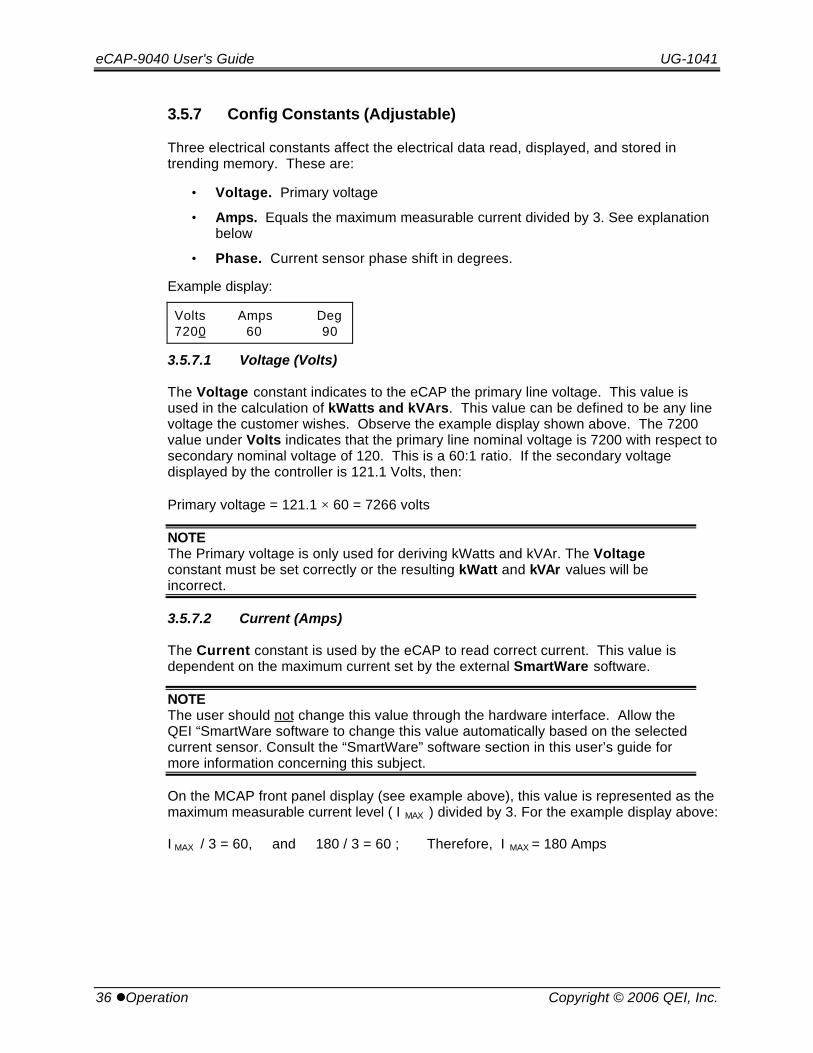
3.5.7 Config Constants (Adjustable)
Three electrical constants affect the electrical data read, displayed, and stored intrending memory. These are:
• Voltage. Primary voltage
• Amps. Equals the maximum measurable current divided by 3. See explanationbelow
• Phase. Current sensor phase shift in degrees.
Example display:
Volts Amps Deg7200 60 90
3.5.7.1 Voltage (Volts)
The Voltage constant indicates to the eCAP the primary line voltage. This value isused in the calculation of kWatts and kVArs. This value can be defined to be any linevoltage the customer wishes. Observe the example display shown above. The 7200value under Volts indicates that the primary line nominal voltage is 7200 with respect tosecondary nominal voltage of 120. This is a 60:1 ratio. If the secondary voltagedisplayed by the controller is 121.1 Volts, then:
Primary voltage = 121.1 × 60 = 7266 volts
NOTEThe Primary voltage is only used for deriving kWatts and kVAr. The Voltageconstant must be set correctly or the resulting kWatt and kVAr values will beincorrect.
3.5.7.2 Current (Amps)
The Current constant is used by the eCAP to read correct current. This value isdependent on the maximum current set by the external SmartWare software.
NOTEThe user should not change this value through the hardware interface. Allow theQEI “SmartWare software to change this value automatically based on the selectedcurrent sensor. Consult the “SmartWare” software section in this user’s guide formore information concerning this subject.
On the MCAP front panel display (see example above), this value is represented as themaximum measurable current level ( I MAX ) divided by 3. For the example display above:
I MAX / 3 = 60, and 180 / 3 = 60 ; Therefore, I MAX = 180 Amps
UG-1041 eCAP-9040 User's Guide
Copyright © 2006 QEI, Inc. Operationl 37
It can be seen from this calculation that the maximum measurable current level in theexample display above is 180 Amps.
Based on the industry standard ratio of 1 Volt = 60 Amps, a current sensor for theexample above, must have an output of 3 Volts @ 180 Amps.
As another example, say that the Config constants are as follows:
Volts Amps Deg 7200 120 90
For the example display above:
I MAX / 3 = 120, and 360 / 3 = 120 ; Therefore, I MAX = 360 Amps
It can be seen from this calculation that the maximum measurable current level in theexample display above is 360 Amps.
Based on the industry standard ratio of 1 Volt = 60 Amps, a current sensor for theexample above, must have an output of 6 Volts @ 360 Amps.
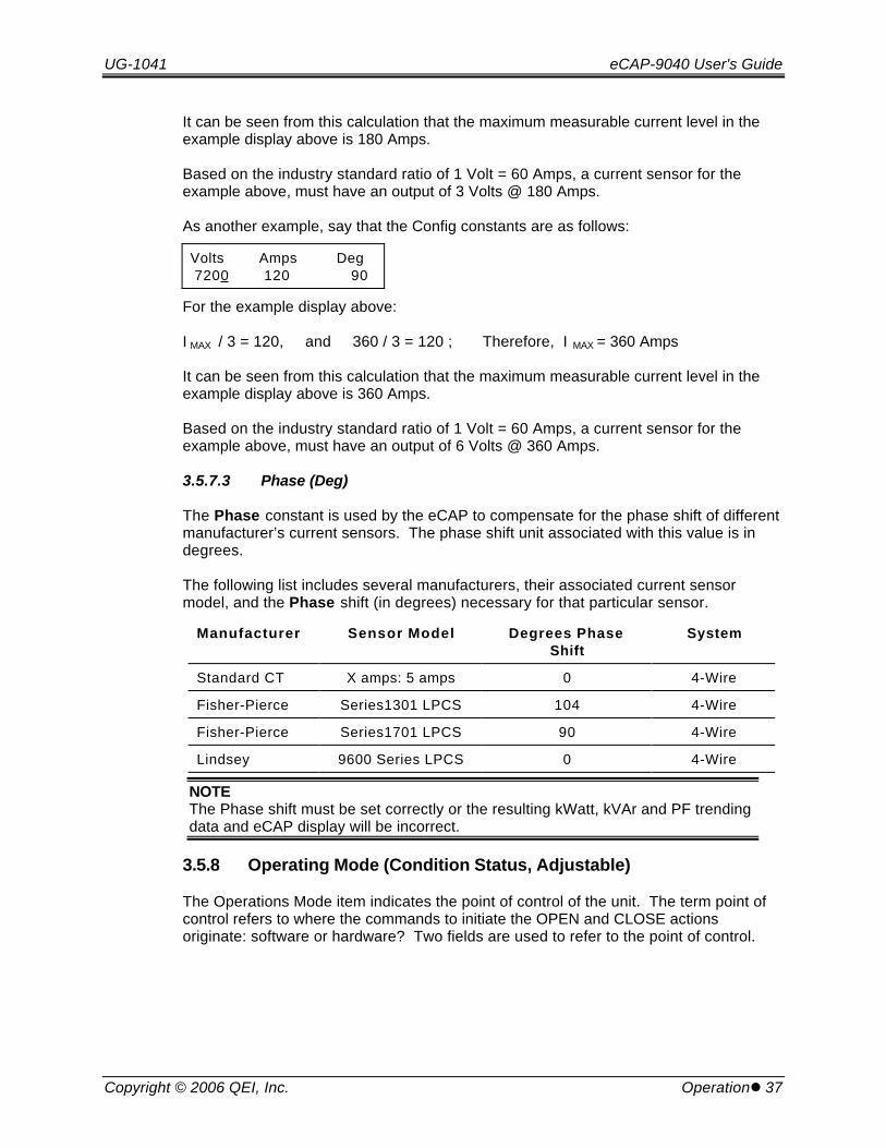
3.5.7.3 Phase (Deg)
The Phase constant is used by the eCAP to compensate for the phase shift of differentmanufacturer’s current sensors. The phase shift unit associated with this value is indegrees.
The following list includes several manufacturers, their associated current sensormodel, and the Phase shift (in degrees) necessary for that particular sensor.
Manufacturer Sensor Model Degrees PhaseShift
System
Standard CT X amps: 5 amps 0 4-Wire
Fisher-Pierce Series1301 LPCS 104 4-Wire
Fisher-Pierce Series1701 LPCS 90 4-Wire
Lindsey 9600 Series LPCS 0 4-Wire
NOTEThe Phase shift must be set correctly or the resulting kWatt, kVAr and PF trendingdata and eCAP display will be incorrect.
3.5.8 Operating Mode (Condition Status, Adjustable)
The Operations Mode item indicates the point of control of the unit. The term point ofcontrol refers to where the commands to initiate the OPEN and CLOSE actionsoriginate: software or hardware? Two fields are used to refer to the point of control.

eCAP-9040 User's Guide UG-1041
38 lOperation Copyright © 2006 QEI, Inc.
The first field titled Comm is used to indicate the point of control from the software sidewhether it be from the firmware or the external “SmartWare”. This field is only relevantwhen the AUTO/MANUAL switch is set on AUTO. Otherwise it is disregarded until atsome point in time the AUTO/MANUAL is set on AUTO.
The second field titled Local is used to indicate the point of control from the hardwareside. This field is only relevant when the AUTO/MANUAL switch is set on MANUAL. Otherwise it is disregarded until the AUTO/MANUAL switch is set on MANAUL.
From the two fields, four points of control (modes) are available to user.
• MANUAL
• AUTO-AUTO
• AUTO-TEST
• AUTO-REMOTE
3.5.8.1 Manual Mode
The MANUAL mode indicates the eCAP is NOT using its internal logic to evaluate andinitiate action (OPEN and CLOSE) of any sort. All actions to be initiated must be donethrough the manual OPEN/CLOSE toggle switch by the user. This mode correspondsto the AUTO/MANUAL switch in the MANUAL position, and it is the only mode that canbe access directly through the hardware AUTO/MANUAL switch. Shown below is anexample of the eCAP display under this mode. Note that the Comm field is to beignored under this mode. Only the Local field condition is of relevance.
Comm LocalAuto Manual
Manual Mode TutorialThis section describes the operation of the eCAP using the OPEN/CLOSE switch on thefront panel, when the AUTO/MANUAL switch is set to MANUAL. There are a number ofinherent delays built into the controller firmware that govern the operation of thecontrol. These delays are explained in the section below.
1. Place the control in its MANUAL mode by placing the AUTO / MANUAL switchin the MANUAL position. When this is done the yellow LED will turn off.
2. The Red and Green LEDs next to the CLOSE / OPEN switch show thecurrent position of the capacitor bank switch.
3. If the capacitor bank is connected to the line, the Red (Close) LED is on. Inthis case, the capacitor bank can be removed from the line by operating theCLOSE / OPEN switch to its OPEN position.
4. When this is done, the Green (Open) LED will begin flashing. This
UG-1041 eCAP-9040 User's Guide
Copyright © 2006 QEI, Inc. Operationl 39
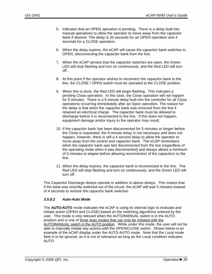
5. Indicates that an OPEN operation is pending. There is a delay built intomanual operations to allow the operator to move away from the capacitorbank if desired. The delay is 20 seconds for an OPEN operation and 4seconds for a CLOSE operation.
6. When the delay expires, the eCAP will cause the capacitor bank switches toOPEN, disconnecting the capacitor bank from the line.
7. When the eCAP senses that the capacitor switches are open, the GreenLED will stop flashing and turn on continuously, and the Red LED will turnoff.
8. At this point if the operator wishes to reconnect the capacitor bank to theline, the CLOSE / OPEN switch must be operated to the CLOSE position.
9. When this is done, the Red LED will begin flashing. This indicates apending Close operation. In this case, the Close operation will not happenfor 5 minutes. There is a 5-minute delay built into the controller for all Closeoperations occurring immediately after an Open operation. The reason forthe delay is that when the capacitor bank was removed from the line itretained an electrical charge. The capacitor bank must be allowed todischarge before it is reconnected to the line. If this does not happen,equipment damage and/or injury to the operator may result.
10. If the capacitor bank has been disconnected for 5 minutes or longer beforethe Close is requested, the 5-minute delay is not necessary and does nothappen, however, there is still a 4 second delay to allow the operator tomove away from the control and capacitor bank. The eCAP rememberswhen the capacitor bank was last disconnected from the line (regardless ofthe operating mode when it was disconnected) and always allows a minimumof 5 minutes to elapse before allowing reconnection of the capacitors to theline.
11. When the delay expires, the capacitor bank is reconnected to the line. TheRed LED will stop flashing and turn on continuously, and the Green LED willturn off.
The Capacitor Discharge delays operate in addition to above delays. This means thatif the bank was recently switched out of the circuit, the eCAP will wait 5 minutes insteadof 4 seconds to reclose the capacitor bank switches
3.5.8.2 Auto-Auto Mode
The AUTO-AUTO mode indicates the eCAP is using its internal logic to evaluate andinitiate action (OPEN and CLOSE) based on the switching algorithms entered by theuser. This mode is only relevant when the AUTO/MANUAL switch is in the AUTOposition and is one of three Auto modes that can only be initiated with theAUTO/MANUAL switch in the AUTO position. While under this mode, the user will not beable to manually initiate any actions with the OPEN/CLOSE switch. Shown below is anexample of the eCAP display under the AUTO-AUTO mode. Note that the Local modefield is to be ignored, as it is not of relevance as long as the Local condition indicatesAUTO.
eCAP-9040 User's Guide UG-1041
40 lOperation Copyright © 2006 QEI, Inc.
Comm LocalAuto Auto
• In addition to the Transient Delay Timer, switching actions initiated by thecontrol under the AUTO-AUTO mode are governed by the following set ofinherent safety features:
• 5-Minute Open-to-Close Delay Timer. Prevents transients caused byswitching in a charged capacitor bank. This feature prevents the capacitor fromclosing until five minutes after the last OPEN operation. (The time isprogrammable for 5 or 10-minutes through “SmartWare”).
• 1-Hour Anti-Oscillation Timer. This feature prevents switching from occurringmore than once per hour (time interval is programmable through “SmartWare”).
• Decade AUTO-REMOTE Mode Switchover Counter. Used in conjunctionwith the anti-oscillation timer above, the eCAP switches itself automatically to theAUTO-REMOTE mode after counting (for example )10 consecutive switchingoperations within 10 hours (number of times/hours is programmable through“SmartWare”). This feature prevents “hunting” caused by improper logic in theswitching algorithm. Proceed to AUTO-REMOTE mode description for furtherinformation.
NOTEUnder this mode the user will not be able to use the manual OPEN andCLOSE toggle switches located on the center portion of the eCAP frontpanel.
3.5.8.3 Auto-Test Mode
The AUTO-TEST mode indicates the eCAP is using its internal logic to evaluate andinitiate action (OPEN and CLOSE) based on evaluation of the switching algorithmsentered. This is one of three Auto modes that is relevant and can be initiated only withthe AUTO/MANUAL switch in the AUTO position. Once in the AUTO position, the controlunit can only be in one of the three modes. While under this mode, the user will not beable to manually initiate any actions with the OPEN/CLOSE switch. With exception tothe 1-Hour Anti-Oscillation Timer, which is disabled, the AUTO-TEST mode acts thesame as the AUTO-AUTO mode. All other inherent times and safety features areobserved. Shown below is an example of the eCAP display under this mode. Note thatthe Local mode field is to be ignored, as it is not of relevance as long as the Localcondition indicates AUTO. Enabling this mode requires the use of SmartWare throughthe SmartView menu. See SmartWare section of this manual.
Comm LocalTest Auto

UG-1041 eCAP-9040 User's Guide
Copyright © 2006 QEI, Inc. Operationl 41
The AUTO-REMOTE mode indicates the eCAP is under the control of anotherintelligent device or system.
Essentially, the eCAP itself becomes a dumb-switch.
With the control set to AUTO-REMOTE, the eCAP will NOT use its internal logic toevaluate and initiate action (OPEN and CLOSE) based on switching algorithms enteredby the user.
With the control set to AUTO-REMOTE, the user will NOT be able to initiate any actionsusing the OPEN/CLOSE switch.
This mode is one of three Auto modes that can only be initiated with theAUTO/MANUAL switch in the AUTO position. Only one of the three can be the point ofaccess at any one time with the AUTO/MANUAL switch in the AUTO position. ThiseCAP uses the AUTO-REMOTE mode in one of two possible functions.
• The first is a residual effect of the 1-Hour Anti-Oscillation Delay Timer safetyfeature. The AUTO-REMOTE mode is enabled by the eCAP after 10consecutive switching operations in 10 hours (1 operation per hour) under theAUTO-AUTO mode. This means the AUTO-AUTO mode is disabled. In thisway the REMOTE mode then acts as a safety feature to prevent ”hunting” oroscillation of the capacitor banks caused by a logically faulty switchingalgorithm.
• The second function is to act as a switch point for an intelligent device orsystem such as SCADA to be controlled remotely, hence the term REMOTE. Allactions are then initiated through the controlling system. The controlling systemalso has the ability to retrieve any information stored in the eCAP unit. Suchinformation would include the real-time based electrical (voltage, current, kW,etc…) and non-electrical parameters (temperature ) and trending data.
Once AUTO-REMOTE mode is enabled, the eCAP can only be switched manually under1 of the following 2 conditions: The first condition is that the user toggles theAUTO/MANUAL switch back to MANAUL at the location of the eCAP. The secondcondition is that the customer uses the SmartWare interfacing software via acommunications link such as a serial cable or a modem to initiate a switching operation.(See SmartWare section of this manual.) Either of these two conditions will then allowthe customer to manually switch the capacitor bank.
eCAP-9040 User's Guide UG-1041
42 lOperation Copyright © 2006 QEI, Inc.
Shown below is the Operating Mode item on the LCD under the AUTO-REMOTEmode.
Comm LocalRemote Auto
3.5.9 Unit ID (Adjustable)
The user is allowed to enter any value from 0 to 9999 as an identification number in thisitem. The SmartWare interfacing software uses this value when downloading data foreach specific unit. All units must have a distinct number. It is recommended that thecustomer use the Serial Number located inside the lid of the control unit.
3.5.10 Temperature (Condition Status, Adjustable)
This item displays three fields and their associated field condition shown below.
Ambient : numeric : Condition statusIndoor : numeric : Condition statusLag : numeric : Adjustable
• Ambient. This is the temperature as recorded by the optional temperaturesensor located on the bottom of the eCAP.
• Indoor. This is a calculated temperature as would be found inside an unheated(or uncooled) building. This value is calculated using the ambient temperatureand the lag time constant. The Indoor temperature will trail the Ambienttemperature by the Lag time constant.
• Lag. This adjustable value is the number of minutes it will take the temperatureinside an unheated (or uncooled) building to reach the ambient temperature. The Indoor temperature is used in all switching algorithms. If switchingon the ambient temperature is desired, set the lag constant to zero.
Shown below is a sample LCD display.
Amb Indoor Lag89 90 2
3.5.11 Switch Status (Condition Status)
Two title headings are shown in this item indicating the condition status of the capacitorswitch.
• Status. Indicates the present status of the capacitor bank. Open or Close
• Pending. Indicates a pending operation to occur. Open indicates openoperation pending when the status of the bank is Close . Close indicates closeoperation pending when the status of the capacitor bank is Open. A blank fieldcondition indicates NO pending operation is about to occur.
Status PendingOpen
UG-1041 eCAP-9040 User's Guide
Copyright © 2006 QEI, Inc. Operationl 43
3.5.12 Operations Count
This counter tracks the number of times that the controller executes an OPENoperation. Each time an OPEN operation is issued, the counter increments by one.
NOTEAn optional electromechanical counter is available for the eCAP.
Operations Count
20
3.5.13 Switching V-Hyst (Adjustable)
Switching Voltage Hysteresis: A product of switching a capacitor bank on-line is avoltage rise, which occurs due to resonance. A possible complication that may arise forsome customers is over-voltage. Suppose a capacitor is off-line (OPEN), and thevoltage is fairly high. Let us suppose also from experience that we know there will be arise of roughly 2 volts once the capacitor bank is CLOSED. If an algorithm intended toswitch on VARs were used, the algorithm would not be able to foresee this unless thecustomer specifically devises a voltage scheme with the VAR switching which requiressome amount of thought.
The VCor (Voltage with Correction) parameter is a feature in the eCAP intended tosolve this problem. Essentially, VCor is a prediction of the voltage for the pendingoperation based on the present voltage value, the status of the capacitor bank and thecorrection values listed under the Switching V-Hist item.
Shown below are the following fields and their associated field conditions:
• ClsV. Post-CLOSE correction value. Value (in volt units plus 1 decimal place)added to the present voltage while status is OPEN to predict the voltage after aCLOSE operation. Prediction is placed in the VCor field in the Voltage,Current item (see Section 3.5.2). This value is only utilized when the status ofthe capacitor bank is OPEN.
• OpnV. Post-OPEN correction value. Value (in volt units plus 1 decimal place)subtracted from the present voltage while status is CLOSED to predict thevoltage after an OPEN operation. Prediction is placed in the VCor field in theVoltage, Current item (see Section 3.5.2). This value is only utilized when thestatus of the capacitor bank is CLOSE.
eCAP-9040 User's Guide UG-1041
44 lOperation Copyright © 2006 QEI, Inc.
• Learn. Allows the customer to set the eCAP in learning mode. Essentially, thecontrol will log the last few operations and learn the voltage rise and drops fromthose operations. The control will then set the ClsV and OpnV accordingly. After 4 or more operations the unit will have predicted a fair approximation ofthe VCor voltage with the banks under the OPEN and CLOSE status. In thisway, the user is free from guessing a value, which may be imprecise. It isrecommended the customer pre-set the ClsV and OpnV values to 2.0 voltswhen setting using this feature. This will give the Learn feature a good startingpoint. The value set under this field is textual and has only two conditions:Yes or No
A sample of the display is shown below:
Learn ClsV OpnVYes 2.0 2.0
UG-1041 eCAP-9040 User's Guide
Copyright © 2006 QEI, Inc. Switching Algorithm Reference Guidel 45
4. Switching Algorithm Reference GuideSetting up the eCAP consists of entering the parameters that govern the automaticoperation of the control. These parameters, termed “Switching Algorithms,” areevaluated by the controller to determine when to switch the capacitor bank into and outof operation. The eCAP switching algorithms can be set up via a computer interfaceusing the QEI “SmartWare” program (described later in this guide). Additionally, theAlgorithms can be configured through the front panel switches.
The QEI eCAPs are very flexible and allow a wide variety of capacitor bank switchingalgorithms. This section describes how to set up the controller to implement anautomatic switching algorithm.
• INTRODUCTIONThis section describes how the controller evaluates switching algorithms. Somegeneral information about this subject is necessary to allow switching algorithmsto be described and entered into the controller.
• COMMON ALGORITHMSThis section contains the most common switching algorithms. If any of theseswitching algorithms fit the users needs, the user only has to enter the selectedschemes into the control.
• CUSTOM ALGORITHMSThe eCAP also allows the user to design a custom switching algorithm and enterit into the control. The next section describes how the eCAP evaluates aswitching algorithm and the complete range of options available in designingcustom switching algorithms.
• FRONT PANEL ENTRYThis section describes how to enter a switching algorithm using the front panelswitches.
eCAP-9040 User's Guide UG-1041
46 lSwitching Algorithm Reference Guide Copyright © 2006 QEI, Inc.
4.1 Introduction
4.1.1 General Considerations
There are a number of items that must be set up for the eCAP to function properly. There are specific parameters that must be entered that describe the electricalenvironment to the eCAP. This is necessary for the control to properly measure thevoltage, current, and power factor and to properly calculate the kWatts and kVArs. Theuser must also enter a switching algorithm that the eCAP uses to determine when toswitch the capacitor bank into and out of the line.
4.1.2 Operating Parameters
The following parameters must be determined for the intended installation and enteredinto the eCAP. The parameters can be entered using the ASmartWare@ program in acomputer attached to the control with a serial RS232 cable. In the case of an eCAPcontrol, the parameters may be optionally entered via the front panel.
• Open Switch Delay
• Close Switch Delay
• Date and Time
• Primary Voltage
• Amp Conversion Constant
• Sensor Phase Shift
• Unit Identity
• Temperature Lag Value
For a detailed description of each of these parameters consult the OPERATION sectionof the user’s guide, under ECAP MENU DESCRIPTION.

UG-1041 eCAP-9040 User's Guide
Copyright © 2006 QEI, Inc. Switching Algorithm Reference Guidel 47
4.1.3 General Information
There are two branches in a switching algorithm: one branch is evaluated when thecapacitor bank switch is open and the other branch is evaluated when the capacitorbank switch is closed. The first branch tells the eCAP when to connect the capacitorbank onto the line; the second branch tells the eCAP when to disconnect the capacitorbank from the line. These two branches are identified by the phrases: Switches Openand Switches Closed. When the switching algorithms are described, a tablecontaining these two phrases as a header indicates them.
Switching algorithms consist of one or more steps in each branch. The example aboveillustrates a sample algorithm for the first step in the SWITCHES OPEN branch, as mightbe seen on the LCD Display of a eCAP, as an item in the “Switches Open” Menu whenconfiguring a eCAP using the front panel switches. A similar display is also shown whenusing QEI “SmartWare” software’s “Algorithm Builder” to configure an eCAP.
Each step contains the following information:
• BRANCH & STEP IDENTIFIER. Indicates the SWITCHES OPEN branch, or SWITCHES CLOSED branch, and step number. There are ten available stepsfor each branch, numbered 0 through 9.
• PARAMETER. The physical parameter to evaluate (i.e., Temperature, Time,Voltage, VARs, etc.).
• FUNCTION. How to evaluate the value of the parameter (i.e., <, >, or =).
• VALUE. The value used to evaluate the measured parameter.
• IF TRUE. What action to take if the evaluation is true (i.e., Close - switch thebank on, Open - switch the bank off, Next go to the next step).
• IF FALSE. What action to take if the evaluation is false.

eCAP-9040 User's Guide UG-1041
48 lSwitching Algorithm Reference Guide Copyright © 2006 QEI, Inc.
In the above example, if the evaluation is TRUE (when the cap bank is OPEN, and themeasured voltage is LESS THAN 120.0 Volts), the controller will CLOSE the cap bank(after any timers have expired). If the evaluation is FALSE (when the cap bank is OPEN,and the measured voltage is GREATER than 120.0 Volts, the controller will advance tothe next step in the SWITCHES OPEN branch, and begin evaluating that step.
The options for each field above are discussed in detail in the tables on the followingpages.
UG-1041 eCAP-9040 User's Guide
Copyright © 2006 QEI, Inc. Switching Algorithm Reference Guidel 49
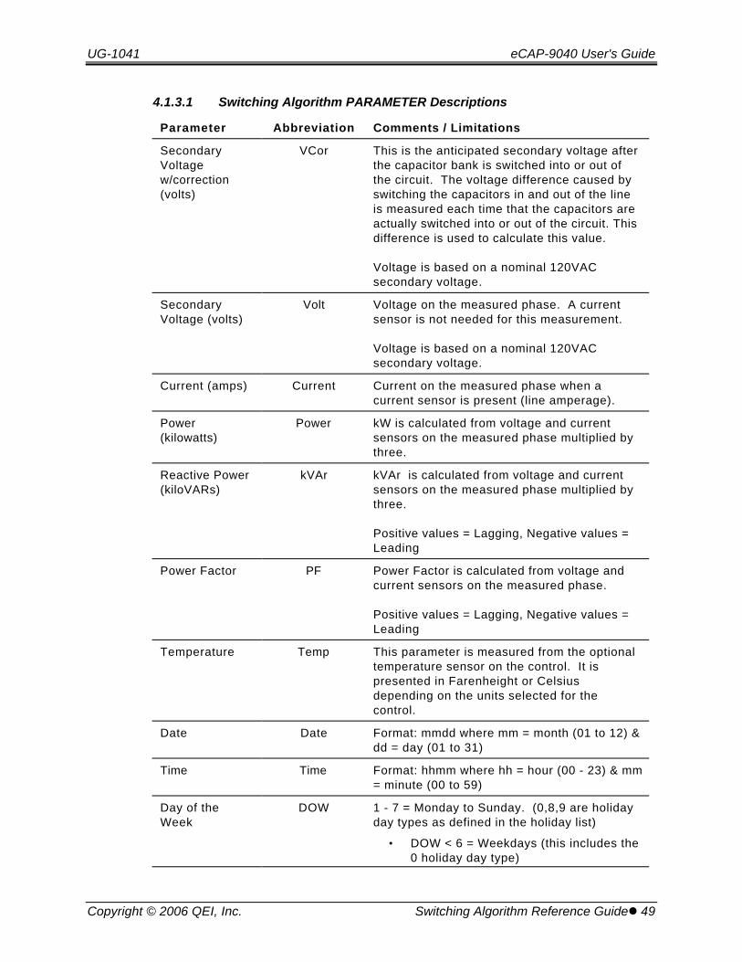
4.1.3.1 Switching Algorithm PARAMETER Descriptions
Parameter Abbreviation Comments / Limitations
SecondaryVoltagew/correction(volts)
VCor This is the anticipated secondary voltage afterthe capacitor bank is switched into or out ofthe circuit. The voltage difference caused byswitching the capacitors in and out of the lineis measured each time that the capacitors areactually switched into or out of the circuit. Thisdifference is used to calculate this value.
Voltage is based on a nominal 120VACsecondary voltage.
SecondaryVoltage (volts)
Volt Voltage on the measured phase. A currentsensor is not needed for this measurement.
Voltage is based on a nominal 120VACsecondary voltage.
Current (amps) Current Current on the measured phase when acurrent sensor is present (line amperage).
Power(kilowatts)
Power kW is calculated from voltage and currentsensors on the measured phase multiplied bythree.
Reactive Power(kiloVARs)
kVAr kVAr is calculated from voltage and currentsensors on the measured phase multiplied bythree.
Positive values = Lagging, Negative values =Leading
Power Factor PF Power Factor is calculated from voltage andcurrent sensors on the measured phase.
Positive values = Lagging, Negative values =Leading
Temperature Temp This parameter is measured from the optionaltemperature sensor on the control. It ispresented in Farenheight or Celsiusdepending on the units selected for thecontrol.
Date Date Format: mmdd where mm = month (01 to 12) &dd = day (01 to 31)
Time Time Format: hhmm where hh = hour (00 - 23) & mm= minute (00 to 59)
Day of theWeek
DOW 1 - 7 = Monday to Sunday. (0,8,9 are holidayday types as defined in the holiday list)
• DOW < 6 = Weekdays (this includes the0 holiday day type)
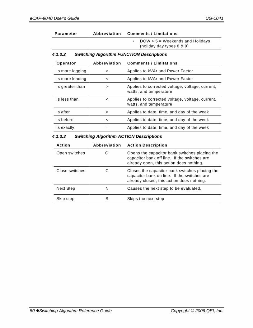
eCAP-9040 User's Guide UG-1041
50 lSwitching Algorithm Reference Guide Copyright © 2006 QEI, Inc.
Parameter Abbreviation Comments / Limitations
• DOW > 5 = Weekends and Holidays(holiday day types 8 & 9)
4.1.3.2 Switching Algorithm FUNCTION Descriptions
Operator Abbreviation Comments / Limitations
Is more lagging > Applies to kVAr and Power Factor
Is more leading < Applies to kVAr and Power Factor
Is greater than > Applies to corrected voltage, voltage, current,watts, and temperature
Is less than < Applies to corrected voltage, voltage, current,watts, and temperature
Is after > Applies to date, time, and day of the week
Is before < Applies to date, time, and day of the week
Is exactly = Applies to date, time, and day of the week
4.1.3.3 Switching Algorithm ACTION Descriptions
Action Abbreviation Action Description
Open switches O Opens the capacitor bank switches placing thecapacitor bank off line. If the switches arealready open, this action does nothing.
Close switches C Closes the capacitor bank switches placing thecapacitor bank on line. If the switches arealready closed, this action does nothing.
Next Step N Causes the next step to be evaluated.
Skip step S Skips the next step

UG-1041 eCAP-9040 User's Guide
Copyright © 2006 QEI, Inc. Switching Algorithm Reference Guidel 51
4.2 Common Switching Algorithms
This section contains a number of common switching algorithms that a user can simplycopy. The numeric values in each of the switching algorithms listed below may not beappropriate for any specific installation and must be determined by the user for theintended installation.
4.2.1 Temperature Control Switching (Example #1)
This switching algorithm uses the temperature sensor on the eCAP to decide when theswitch the capacitors into and out of the line. It is one of the simplest switchingalgorithms and does not require a current sensor.
Switches OPEN
Parameter Function Value True False
Temp > 80* Close Open
Switches CLOSED
Parameter Function Value True False
Temp < 70* Open Close
*The temperatures used to switch the capacitor bank on and off should be determinedby the user. Using the above values the capacitor bank would be switched on when theIndoor temperature exceeds 80F and off when the Indoor temperature dropped below70F. The temperatures selected should not be very close together (i.e. on at 75 off at73). This could cause undesired switching operations.
NOTEThe Indoor temperature is used all switching algorithms. If the ambient temperatureis desired, set the temperature lag constant to zero.
4.2.2 Temperature Control Switching (Example #2)
Switches Open Status Switches Close StatusT F T F
0) Temp < 50 C N 0) Temp < 50 C N1) Temp > 90 C O 1) Temp > 90 C O
The algorithm indicated above will close the banks for temperatures above 90 degreesand below 50 degrees Fahrenheit. For temperatures in the “mild zone” the banksremain open. The purpose of the broad range in-between 50 and 90 is due to the lagtimes involved in temperature changes. This also allows fewer switching operationsthereby avoiding hunting where sudden changes in climates might occur. Temperatureswitching is more suited to seasonal loads.

eCAP-9040 User's Guide UG-1041
52 lSwitching Algorithm Reference Guide Copyright © 2006 QEI, Inc.
4.2.3 Time & Date Control
This switching algorithm uses the internal clock and calendar in the control to determinewhen to switch the capacitor bank in and out of the line. It does not need a currentsensor.
Switches OPEN
Parameter Function Value True False
DOW < 6* Next Open
Time > 0800* Next Open
Time < 1800* Close Open
Switches CLOSED
Parameter Function Value True False
DOW < 6* Next Open
Time > 0800* Next Open
Time < 1800* Close Open
*The times and dates should be selected by the user to meet the needs of the desiredoperation. The switching algorithm above switches the capacitor bank in if it is aweekday and the time is between 8AM and 6PM. If it is not a weekday or the time isbefore 8AM or after 6PM, the capacitor bank is switched out of the line.
4.2.4 Time of Day Switching
Switches Open Status Switches Close Status
T F T F
0) Time < 600 O N 0) Time < 600 O N
1) Time > 1800 O N 1) Time > 1800 O N
2) Time < 1200 C N 2) Time < 1200 C N
3) Time > 1300 C O 3) Time > 1300 C O
The algorithm indicated above will close the banks in from 6 AM to 12 PM. After 12 PMthe banks will open until 1 PM to account for lunchtime inactivity. After 1 PM the bankswill close again until 6 PM whereupon the banks will remain open until the following daywhereupon the process repeats.
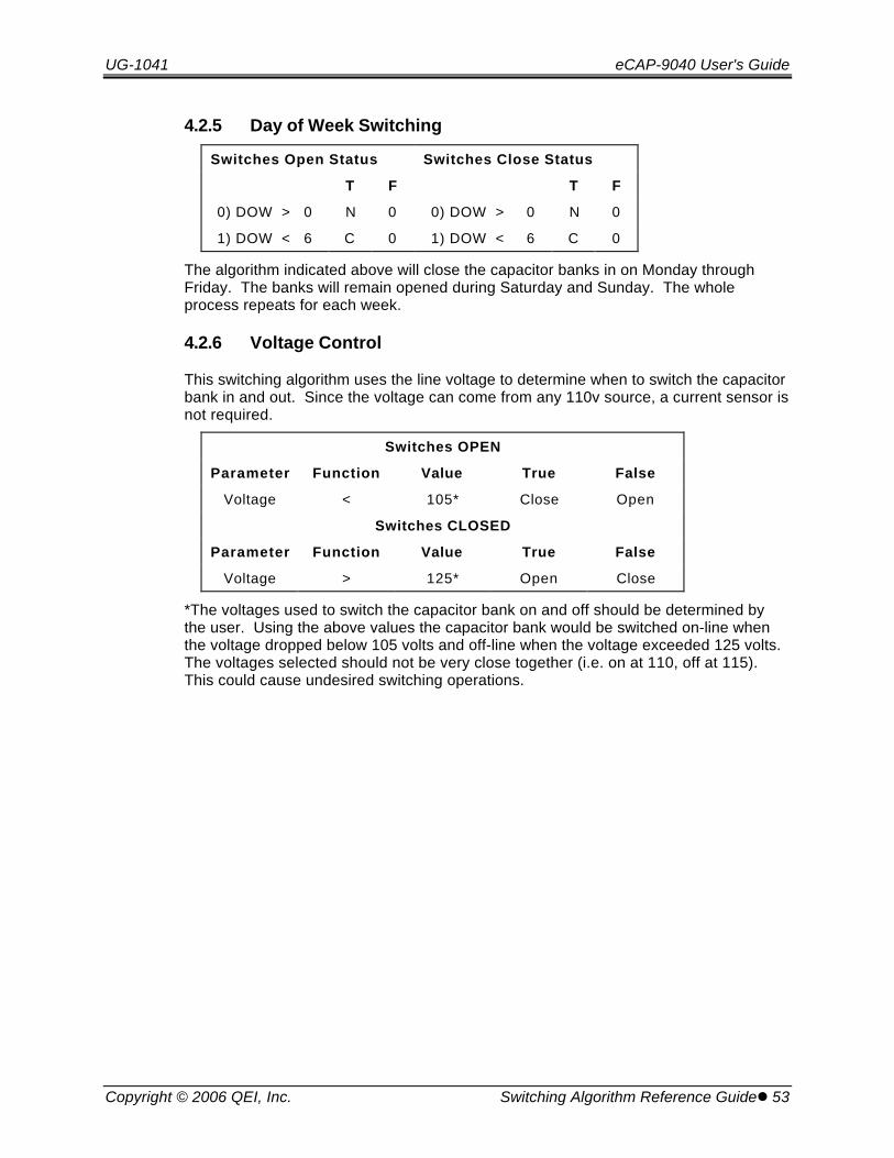
UG-1041 eCAP-9040 User's Guide
Copyright © 2006 QEI, Inc. Switching Algorithm Reference Guidel 53
4.2.5 Day of Week Switching
Switches Open Status Switches Close Status
T F T F
0) DOW > 0 N 0 0) DOW > 0 N 0
1) DOW < 6 C 0 1) DOW < 6 C 0
The algorithm indicated above will close the capacitor banks in on Monday throughFriday. The banks will remain opened during Saturday and Sunday. The wholeprocess repeats for each week.
4.2.6 Voltage Control
This switching algorithm uses the line voltage to determine when to switch the capacitorbank in and out. Since the voltage can come from any 110v source, a current sensor isnot required.
Switches OPEN
Parameter Function Value True False
Voltage < 105* Close Open
Switches CLOSED
Parameter Function Value True False
Voltage > 125* Open Close
*The voltages used to switch the capacitor bank on and off should be determined bythe user. Using the above values the capacitor bank would be switched on-line whenthe voltage dropped below 105 volts and off-line when the voltage exceeded 125 volts. The voltages selected should not be very close together (i.e. on at 110, off at 115). This could cause undesired switching operations.
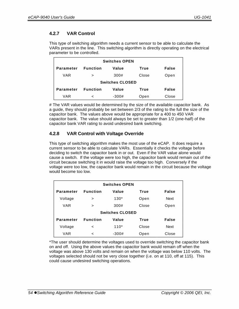
eCAP-9040 User's Guide UG-1041
54 lSwitching Algorithm Reference Guide Copyright © 2006 QEI, Inc.
4.2.7 VAR Control
This type of switching algorithm needs a current sensor to be able to calculate theVARs present in the line. This switching algorithm is directly operating on the electricalparameter to be controlled.
Switches OPEN
Parameter Function Value True False
VAR > 300# Close Open
Switches CLOSED
Parameter Function Value True False
VAR < -300# Open Close
# The VAR values would be determined by the size of the available capacitor bank. Asa guide, they should probably be set between 2/3 of the rating to the full the size of thecapacitor bank. The values above would be appropriate for a 400 to 450 VARcapacitor bank. The value should always be set to greater than 1/2 (one-half) of thecapacitor bank VAR rating to avoid undesired bank switching.
4.2.8 VAR Control with Voltage Override
This type of switching algorithm makes the most use of the eCAP. It does require acurrent sensor to be able to calculate VARs. Essentially it checks the voltage beforedeciding to switch the capacitor bank in or out. Even if the VAR value alone wouldcause a switch. If the voltage were too high, the capacitor bank would remain out of thecircuit because switching it in would raise the voltage too high. Conversely if thevoltage were too low, the capacitor bank would remain in the circuit because the voltagewould become too low.
Switches OPEN
Parameter Function Value True False
Voltage > 130* Open Next
VAR > 300# Close Open
Switches CLOSED
Parameter Function Value True False
Voltage < 110* Close Next
VAR < -300# Open Close
*The user should determine the voltages used to override switching the capacitor bankon and off. Using the above values the capacitor bank would remain off when thevoltage was above 130 volts and remain on when the voltage was below 110 volts. Thevoltages selected should not be very close together (i.e. on at 110, off at 115). Thiscould cause undesired switching operations.
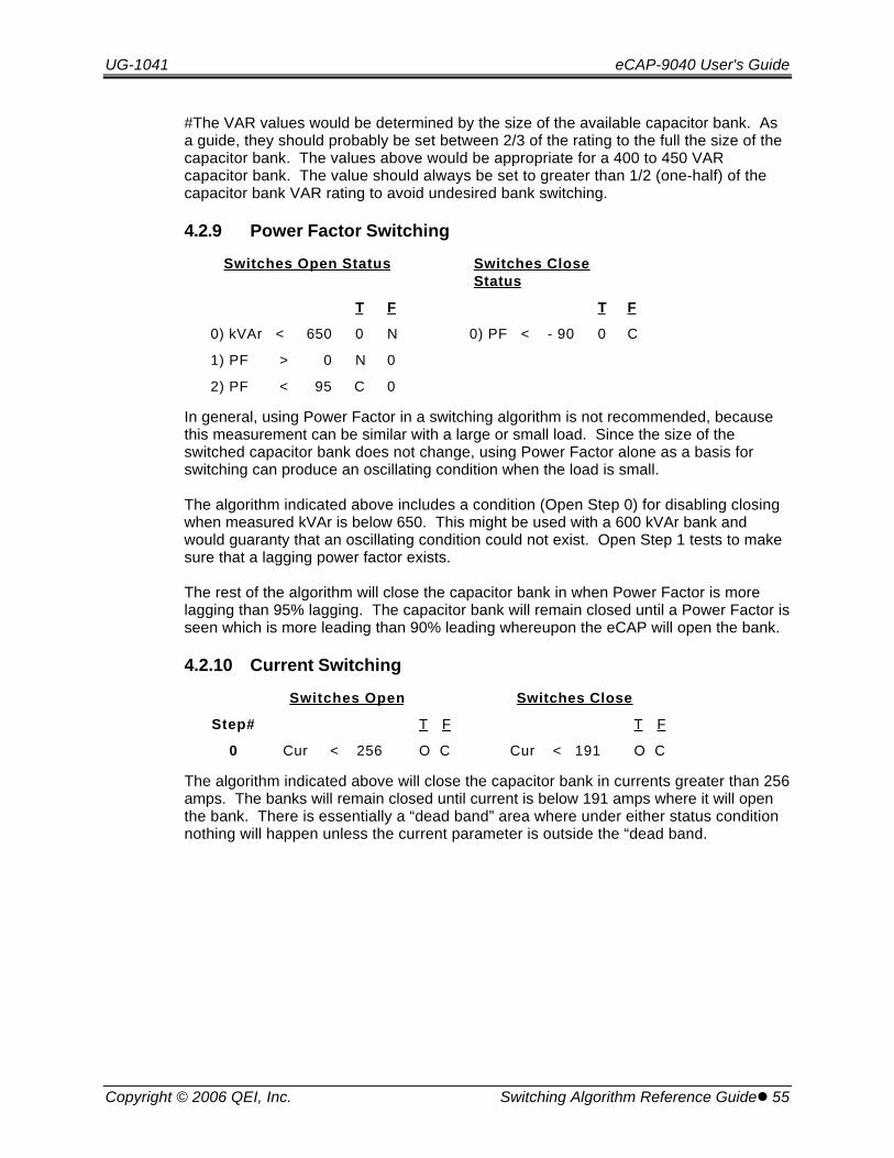
UG-1041 eCAP-9040 User's Guide
Copyright © 2006 QEI, Inc. Switching Algorithm Reference Guidel 55
#The VAR values would be determined by the size of the available capacitor bank. Asa guide, they should probably be set between 2/3 of the rating to the full the size of thecapacitor bank. The values above would be appropriate for a 400 to 450 VARcapacitor bank. The value should always be set to greater than 1/2 (one-half) of thecapacitor bank VAR rating to avoid undesired bank switching.
4.2.9 Power Factor Switching
Switches Open Status Switches CloseStatus
T F T F
0) kVAr < 650 0 N 0) PF < - 90 0 C
1) PF > 0 N 0
2) PF < 95 C 0
In general, using Power Factor in a switching algorithm is not recommended, becausethis measurement can be similar with a large or small load. Since the size of theswitched capacitor bank does not change, using Power Factor alone as a basis forswitching can produce an oscillating condition when the load is small.
The algorithm indicated above includes a condition (Open Step 0) for disabling closingwhen measured kVAr is below 650. This might be used with a 600 kVAr bank andwould guaranty that an oscillating condition could not exist. Open Step 1 tests to makesure that a lagging power factor exists.
The rest of the algorithm will close the capacitor bank in when Power Factor is morelagging than 95% lagging. The capacitor bank will remain closed until a Power Factor isseen which is more leading than 90% leading whereupon the eCAP will open the bank.
4.2.10 Current Switching
Switches Open Switches Close
Step# T F T F
0 Cur < 256 O C Cur < 191 O C
The algorithm indicated above will close the capacitor bank in currents greater than 256amps. The banks will remain closed until current is below 191 amps where it will openthe bank. There is essentially a “dead band” area where under either status conditionnothing will happen unless the current parameter is outside the “dead band.
eCAP-9040 User's Guide UG-1041
56 lSwitching Algorithm Reference Guide Copyright © 2006 QEI, Inc.
4.3 Customized Switching Algorithms
This section describes how switching algorithms are evaluated and contains a completelist of functions that are available with descriptions of any limitations. Beforeattempting to develop a custom-switching algorithm, it is recommended thatthe user review the common switching algorithms in the previous section toget a sense of how switching algorithms are used.
4.3.1 Switching Algorithm Evaluation Process
• The eCAP first determines whether the capacitor bank switches are open orclosed. It then picks the appropriate switching algorithm branch for evaluation. Only one of the two branches are evaluated.
• It evaluates the first step in the branch by calculating the selected parameterand checking it against the parameter value entered using the comparisonfunction selected. If the evaluation is true, it performs the action selected forTRUE otherwise it performs the FALSE action.
• If the action selected is Open or Close, the switches are Opened or Closed asappropriate.
• If the switches are already open, opening them has no effect. This thenbecomes a “NULL” action. The same thing happens if the switches are alreadyclosed. A close action has no effect and is a “NULL” action. If the actionselected is Next, the evaluation process continues with the next step.
• If any step has any combination of Open or Close actions for both the True andFalse results, that step is the final step in the process.
• The overall result of the evaluation process is either that the switches remain intheir current position or the switches are changed (opened or closed asappropriate).
UG-1041 eCAP-9040 User's Guide
Copyright © 2006 QEI, Inc. Switching Algorithm Reference Guidel 57
4.3.2 Switching Algorithm Development Considerations
• Any step that does not contain a NEXT step action is the end of the switchingalgorithms for that branch.
• The “Switches Open” and “Switches Closed” branches do NOT need to havethe same number of steps.
• When switching on VARs, Voltage, or Power Factor, make sure that there isenough separation in the values for the Open and Closed branches so that theswitching algorithm does not oscillate. Oscillation can occur when the capacitorbank is switched in, causing a change in electrical conditions, and the SwitchesClosed branch evaluation results in an Open action. In this case, the twobranches will alternately result in Close and then Open actions). There aretimers and logic in the eCAP to detect and limit the number of oscillations.
• The best solution is to be aware that such events can occur and to developswitching algorithms that do not result in oscillations.
• The current sensor must be placed between the power source and thecapacitor bank switches for proper operation.

eCAP-9040 User's Guide UG-1041
58 lSmartWare Copyright © 2006 QEI, Inc.
5. SmartWare"SmartWare" is the name of the QEI software that provides a graphical interface used toconfigure and retrieve data from the eCAP via its front panel 9-pin RS-232 connector. This section of the eCAP manual covers the installation and operation of the"SmartWare" software. This section contains the following information:
• General configuration and set up information
• Configuring a eCAP via "SmartWare"
Setting configuration parameters
Entering common switching algorithms
Entering custom switching algorithms
Setting Historical data parameters
• Configuring "SmartWare"
Setting Holidays
Setting Historical data storage
• Remote eCAP operation
Viewing real-time data
Capacitor bank operations
Retrieving historical data
Retrieving the controls operation log
SmartMemo's
• Capacitor Simulator
• "SmartWare" Reference. Describes each field and function of all "SmartWare"windows.
This manual assumes that the user is familiar with standard Microsoft Windowsoperating procedures. If this not the case, consult any standard reference forinformation on Windows.
• Version. This section covers Version 4.0.X of the QEI “SmartWare” Software.
• Minimum Computer Hardware Requirements
Any computer running Windows 98, Windows NT, Windows 2000 orWindows XP operating system will work for the "SmartWare" software.
10 megabytes of free hard drive space
• Program Installation. Use the standard procedures for installing Windowssoftware (place the CD or first installation disk in it's drive and RUN Setup.exe).
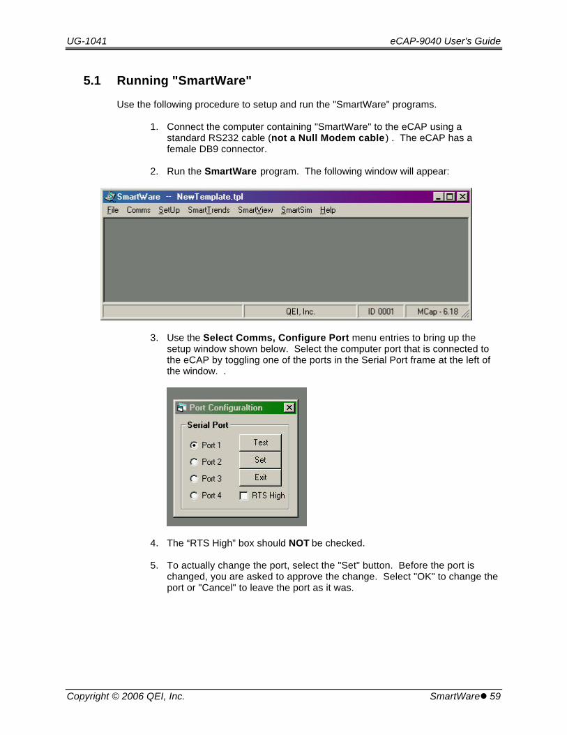
UG-1041 eCAP-9040 User's Guide
Copyright © 2006 QEI, Inc. SmartWarel 59
5.1 Running "SmartWare"
Use the following procedure to setup and run the "SmartWare" programs.
1. Connect the computer containing "SmartWare" to the eCAP using astandard RS232 cable (not a Null Modem cable) . The eCAP has afemale DB9 connector.
2. Run the SmartWare program. The following window will appear:
3. Use the Select Comms, Configure Port menu entries to bring up thesetup window shown below. Select the computer port that is connected tothe eCAP by toggling one of the ports in the Serial Port frame at the left ofthe window. .
4. The “RTS High” box should NOT be checked.
5. To actually change the port, select the "Set" button. Before the port ischanged, you are asked to approve the change. Select "OK" to change theport or "Cancel" to leave the port as it was.
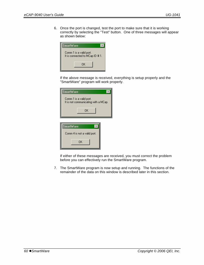
eCAP-9040 User's Guide UG-1041
60 lSmartWare Copyright © 2006 QEI, Inc.
6. Once the port is changed, test the port to make sure that it is workingcorrectly by selecting the "Test" button. One of three messages will appearas shown below:
If the above message is received, everything is setup properly and the"SmartWare" program will work properly.
If either of these messages are received, you must correct the problembefore you can effectively run the SmartWare program.
7. The SmartWare program is now setup and running. The functions of theremainder of the data on this window is described later in this section.
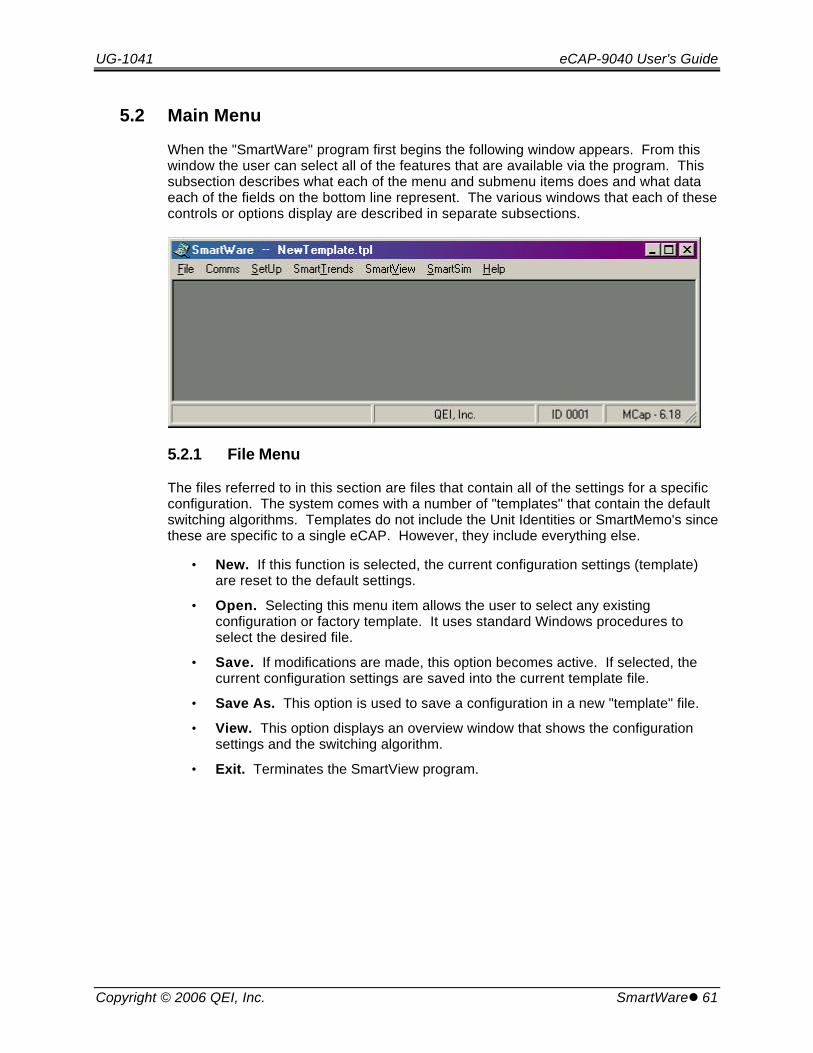
UG-1041 eCAP-9040 User's Guide
Copyright © 2006 QEI, Inc. SmartWarel 61
5.2 Main Menu
When the "SmartWare" program first begins the following window appears. From thiswindow the user can select all of the features that are available via the program. Thissubsection describes what each of the menu and submenu items does and what dataeach of the fields on the bottom line represent. The various windows that each of thesecontrols or options display are described in separate subsections.
5.2.1 File Menu
The files referred to in this section are files that contain all of the settings for a specificconfiguration. The system comes with a number of "templates" that contain the defaultswitching algorithms. Templates do not include the Unit Identities or SmartMemo's sincethese are specific to a single eCAP. However, they include everything else.
• New. If this function is selected, the current configuration settings (template)are reset to the default settings.
• Open. Selecting this menu item allows the user to select any existingconfiguration or factory template. It uses standard Windows procedures toselect the desired file.
• Save. If modifications are made, this option becomes active. If selected, thecurrent configuration settings are saved into the current template file.
• Save As. This option is used to save a configuration in a new "template" file.
• View. This option displays an overview window that shows the configurationsettings and the switching algorithm.
• Exit. Terminates the SmartView program.
eCAP-9040 User's Guide UG-1041
62 lSmartWare Copyright © 2006 QEI, Inc.
5.2.2 Comms Menu
This menu item is used to setup and carry on communications with the eCAP.
• Establish Link. This option establishes communications with the eCAPconnected to the serial port. When communications is established the Unit IDand Firmware Version will be shown at the bottom right of the SmartWarescreen.
• Read. This command reads the settings and switching algorithms from thecontrol.
• Send. This command writes the settings and switching algorithm from thecomputer into the eCAP.
• Configure Port. This option is used to select the computers serial port that isconnected to the eCAP.
5.2.3 Setup Menu
The options under this menu are used to configure the "SmartWare" program, seteCAP parameters, and define custom switching algorithms.
• SmartWare. This option is used to establish storage parameters for historicaldata for the different eCAPs that a utility has. This allows the computer to becarried from eCAP to eCAP and record the historical information from eachcontrol separately.
• Hardware. This option is used to set the power line parameters, the currentsensor parameters, and the default switching voltage hysterisis to the eCAP.
• Timing. This option is used to set the timing values and enable or disable thevarious timers that control the operation of the eCAP.
• Switching algorithm. This window that this option brings up is used to definecustom switching algorithms for the eCAP.
• Holidays. This option is used to define the holidays that the eCAP will honor.
• Identification. This option is used to change the eCAP identity and to store anoptional memo into the eCAP.
• Temperature Units. This option is used to select Fahrenheit or Celsiustemperature units.
• Calibration. This function is only used in factory or by a qualified technician toset the two calibration factors in the eCAP. This function is discussed in afollowing section.
• Reset. Resets all settings in the eCAP (except calibration) to factory defaults.
UG-1041 eCAP-9040 User's Guide
Copyright © 2006 QEI, Inc. SmartWarel 63
5.2.4 SmartTrends Menu
This menu item is used to retrieve and display historical data from the eCAP.
• Download. Use this function to retrieve data from an eCAP.
• Smartgraph. This brings up the Smartgraph's Historial Data Graphingsoftware.
• Operations Log. This command retrieves (and displays) the log of switchingoperations performed by or through the eCAP.
5.2.5 SmartView Menu
This option brings up a window that contains both the current operation conditions ofthe control and is used to perform remote operation of the capacitor bank through theattached computer. It is discussed in the Remote Operations Section.
5.2.6 SmartSim
This menu items enables or disables the eCAP simulator. This function is usedprimarily to demonstrate or learn how the eCAPs work. See the Simulator Section for adescription of what the simulator is and how to use it.
5.2.7 Help
• SmartWare Help Topics. This menu option brings up a windows help file withdetailed information about “SmartWare.”
• About SmartWare. SmartWare version and ownership data.
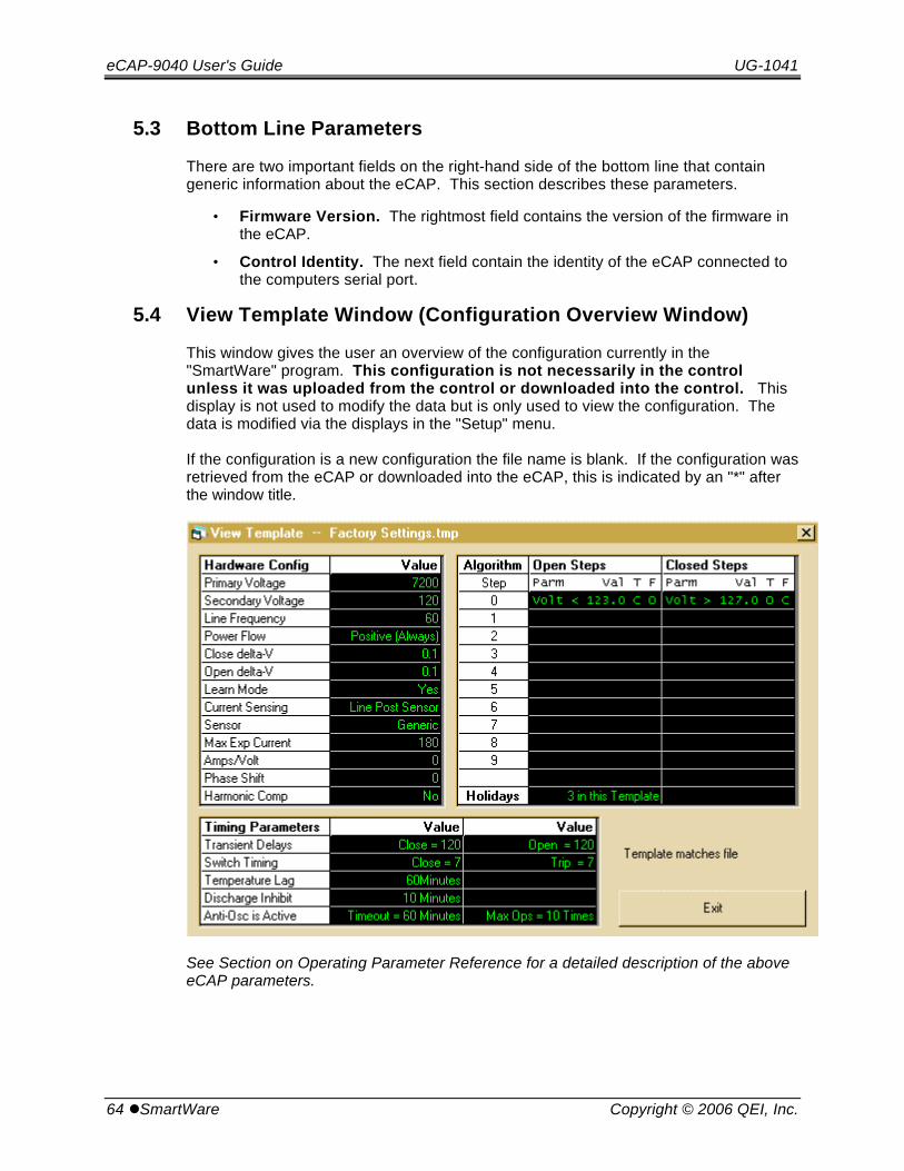
eCAP-9040 User's Guide UG-1041
64 lSmartWare Copyright © 2006 QEI, Inc.
5.3 Bottom Line Parameters
There are two important fields on the right-hand side of the bottom line that containgeneric information about the eCAP. This section describes these parameters.
• Firmware Version. The rightmost field contains the version of the firmware inthe eCAP.
• Control Identity. The next field contain the identity of the eCAP connected tothe computers serial port.
5.4 View Template Window (Configuration Overview Window)
This window gives the user an overview of the configuration currently in the"SmartWare" program. This configuration is not necessarily in the controlunless it was uploaded from the control or downloaded into the control. Thisdisplay is not used to modify the data but is only used to view the configuration. Thedata is modified via the displays in the "Setup" menu.
If the configuration is a new configuration the file name is blank. If the configuration wasretrieved from the eCAP or downloaded into the eCAP, this is indicated by an "*" afterthe window title.
See Section on Operating Parameter Reference for a detailed description of the aboveeCAP parameters.
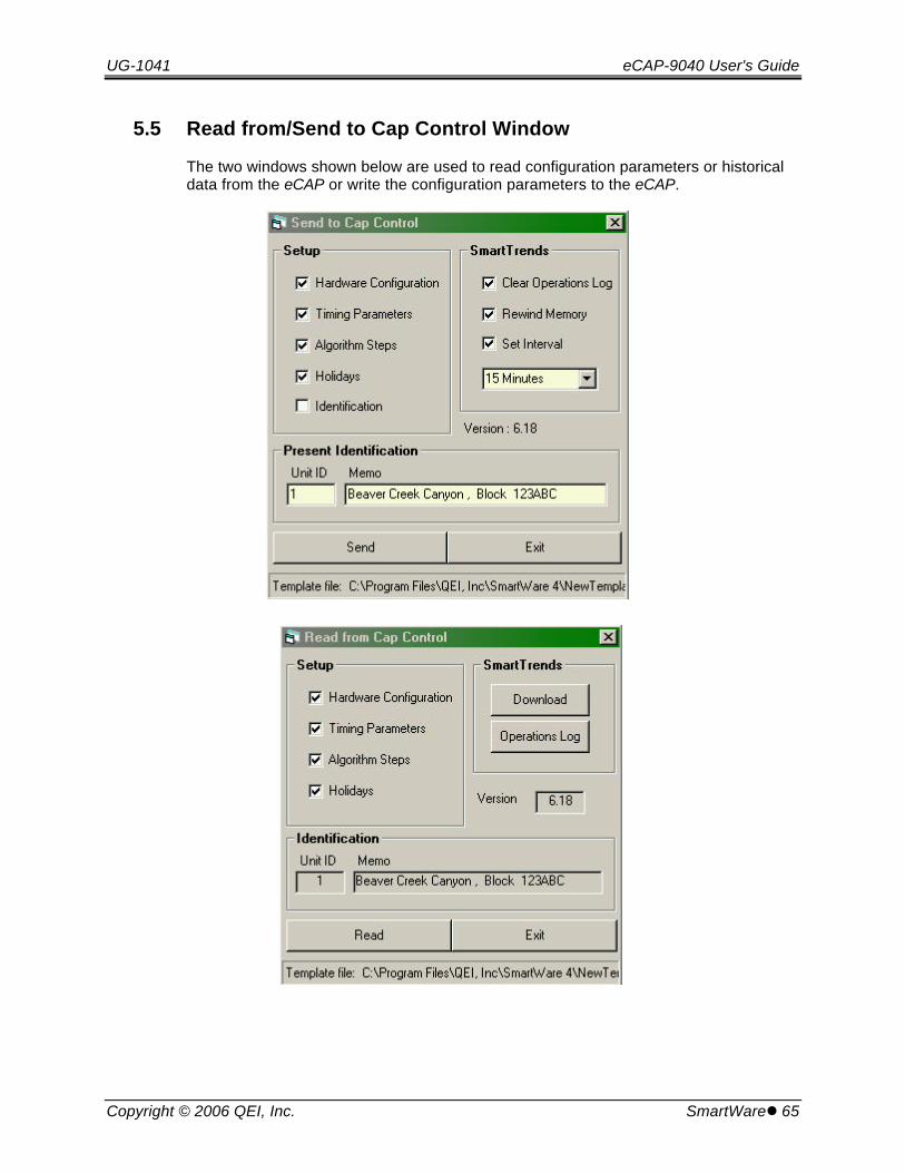
UG-1041 eCAP-9040 User's Guide
Copyright © 2006 QEI, Inc. SmartWarel 65
5.5 Read from/Send to Cap Control Window
The two windows shown below are used to read configuration parameters or historicaldata from the eCAP or write the configuration parameters to the eCAP.

eCAP-9040 User's Guide UG-1041
66 lSmartWare Copyright © 2006 QEI, Inc.
5.6 Setup Fame
This set of options is used to select which set of operating parameter are read (orwritten) to the eCAP. Select one or more of these sets of parameters.
• Send only. If "Identification" is selected, the Unit ID and Memo from theIdentification frame are written into the eCAP.
• SmartTrends (Read). The two functions on this frame are used to readhistorical data from the eCAP.
Download reads historical measurement data.
Operations Log reads the log of switching operations.
• SmartTrends (Send). There are three options and one editable field in thewrite version of the window.
Clear Operations Log. This option causes the eCAP to reset itshistorical operations log.
Rewind Memory. This option causes the eCAP to reset the historicalmeasurements that it maintains.
Set Interval. This option causes the historical data storage intervalto be changed to the number in the field immediately below the optionto one of the available values.
• Version. This field displays the firmware version in the control.
• Identification frame. This frame contains two fields:
Unit ID. The eCAP identity.
Memo. The memo stored in the eCAP memory.
• Bottom Panel. This panel shows which configuration file was the source of theconfiguration data.
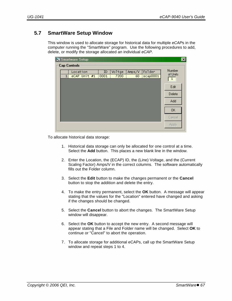
UG-1041 eCAP-9040 User's Guide
Copyright © 2006 QEI, Inc. SmartWarel 67
5.7 SmartWare Setup Window
This window is used to allocate storage for historical data for multiple eCAPs in thecomputer running the "SmartWare" program. Use the following procedures to add,delete, or modify the storage allocated an individual eCAP.
To allocate historical data storage:
1. Historical data storage can only be allocated for one control at a time. Select the Add button. This places a new blank line in the window.
2. Enter the Location, the (ECAP) ID, the (Line) Voltage, and the (CurrentScaling Factor) Amps/V in the correct columns. The software automaticallyfills out the Folder column.
3. Select the Edit button to make the changes permanent or the Cancelbutton to stop the addition and delete the entry.
4. To make the entry permanent, select the OK button. A message will appearstating that the values for the "Location" entered have changed and askingif the changes should be changed.
5. Select the Cancel button to abort the changes. The SmartWare Setupwindow will disappear.
6. Select the OK button to accept the new entry. A second message willappear stating that a File and Folder name will be changed. Select OK tocontinue or "Cancel" to abort the operation.
7. To allocate storage for additional eCAPs, call up the SmartWare Setupwindow and repeat steps 1 to 4.

eCAP-9040 User's Guide UG-1041
68 lSmartWare Copyright © 2006 QEI, Inc.
5.7.1 Deleting an Entry
1. Select any field of the entry to delete.
2. Select the Delete button to permanently remove the entry.
3. When this is done, a second message appears stating that files will bedeleted and requesting permission to make the changes.
4. If permission is granted, the deletion becomes permanent.
5.7.2 Modifying an Entry
1. Select any field of the entry to modify.
2. Select the Edit button to make the fields enterable. The alterable fields ofthe entry are highlighted. .
3. Change the one or more field values.
4. Select the Edit button to make the changes permanent.
5. Select the Cancel button to ignore the changes and close the "SmartWare"Setup window.
6. Selecting any other entry or the OK button causes the following message toappear: "The values for "Location" have changed, Save the changes?"
7. Select Cancel to ignore the changes.
8. Select OK to make the changes permanent. When this is done, a secondmessage appears stating that a file will be changed and requestingpermission to make the changes.
9. If permission is granted, the changes become permanent. If denied, thechanges are ignored.

UG-1041 eCAP-9040 User's Guide
Copyright © 2006 QEI, Inc. SmartWarel 69
5.8 Hardware Configuration Window
The Hardware Configuration Window is used to specify parameters that describe thepower line to the eCAP. These parameters in this window are used by the eCAP toproperly process the information that it receives from the voltage and current sensorsand make accurate decisions about switching the capacitor bank in and out of the line
The many of parameters on this window are also described in Section 3.2 OperatingParameter Reference. However, most of the parameters are given slightly differentnames in this window and there are a number of completely new parameters. In thedescriptions below, parameters reference names used in Section 3.2 are enclosed insquare brackets.
5.8.1 Voltage Constants Frame
The constants in this frame are the conversion constants used by the eCAP to correctlyconvert the voltage and current inputs to their correct engineering values. This isnecessary so that the control can correctly and accurately calculate kWatt, kVAr, andPower Factor values.
• Primary Phase-Neutral (voltage) [Config Constants - Volts]. This value isthe primary line to ground voltage (in volts) that corresponds to the nominalsecondary voltage. This value is used when deriving kWatts, kVArs, and PowerFactor.
• Secondary (Metering): This is the nominal secondary voltage (120 or 240).
• Line Frequency: This is the frequency in Hz of the system (60 or 50 Hz).

eCAP-9040 User's Guide UG-1041
70 lSmartWare Copyright © 2006 QEI, Inc.
5.8.2 Power Direction Frame
The control can be configured to detect the direction of current flow. The information inthis frame directs the eCAP how to treat power flow.
• Positive. If this option is selected the power flow is always positive regardlessof its direction.
• Normal. This option directs the eCAP to treat flow away from the substation aspositive and into the substation as negative. This allows the switching algorithmto be dependent on the direction of power flow.
• Reverse. This option also directs the eCAP to treat power flow as a signedvalue. However in this case, the signs are reversed. Flow away from thesubstation is negative and into the substation
5.8.3 Switching Delta-V Frame
One of the effects of switching a bank of capacitors on line is that the line voltage rises. The opposite occurs when the capacitor bank is removed from the line. The QEI eCAPis capable of taking this effect into consideration when automatically switching acapacitor bank into or out of the line. The parameters in this frame are used toestimate the effect of switching the capacitor bank into and out of the line.
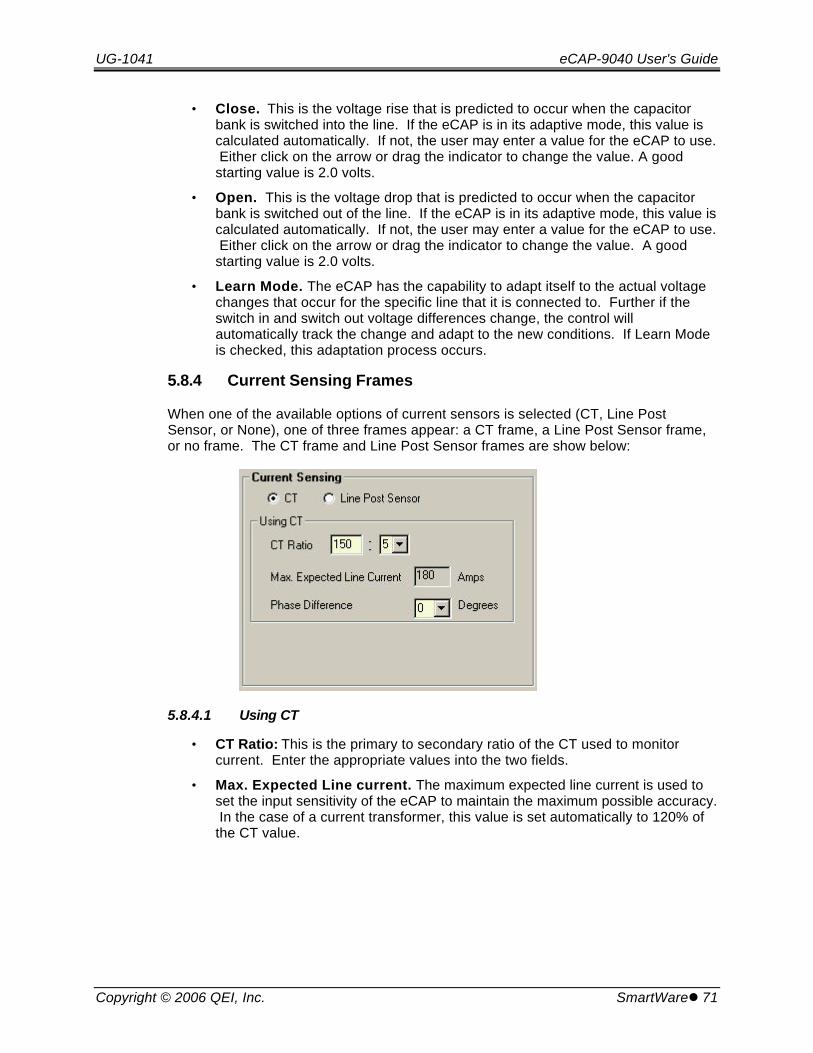
UG-1041 eCAP-9040 User's Guide
Copyright © 2006 QEI, Inc. SmartWarel 71
• Close. This is the voltage rise that is predicted to occur when the capacitorbank is switched into the line. If the eCAP is in its adaptive mode, this value iscalculated automatically. If not, the user may enter a value for the eCAP to use. Either click on the arrow or drag the indicator to change the value. A goodstarting value is 2.0 volts.
• Open. This is the voltage drop that is predicted to occur when the capacitorbank is switched out of the line. If the eCAP is in its adaptive mode, this value iscalculated automatically. If not, the user may enter a value for the eCAP to use. Either click on the arrow or drag the indicator to change the value. A goodstarting value is 2.0 volts.
• Learn Mode. The eCAP has the capability to adapt itself to the actual voltagechanges that occur for the specific line that it is connected to. Further if theswitch in and switch out voltage differences change, the control willautomatically track the change and adapt to the new conditions. If Learn Modeis checked, this adaptation process occurs.
5.8.4 Current Sensing Frames
When one of the available options of current sensors is selected (CT, Line PostSensor, or None), one of three frames appear: a CT frame, a Line Post Sensor frame,or no frame. The CT frame and Line Post Sensor frames are show below:
5.8.4.1 Using CT
• CT Ratio: This is the primary to secondary ratio of the CT used to monitorcurrent. Enter the appropriate values into the two fields.
• Max. Expected Line current. The maximum expected line current is used toset the input sensitivity of the eCAP to maintain the maximum possible accuracy. In the case of a current transformer, this value is set automatically to 120% ofthe CT value.
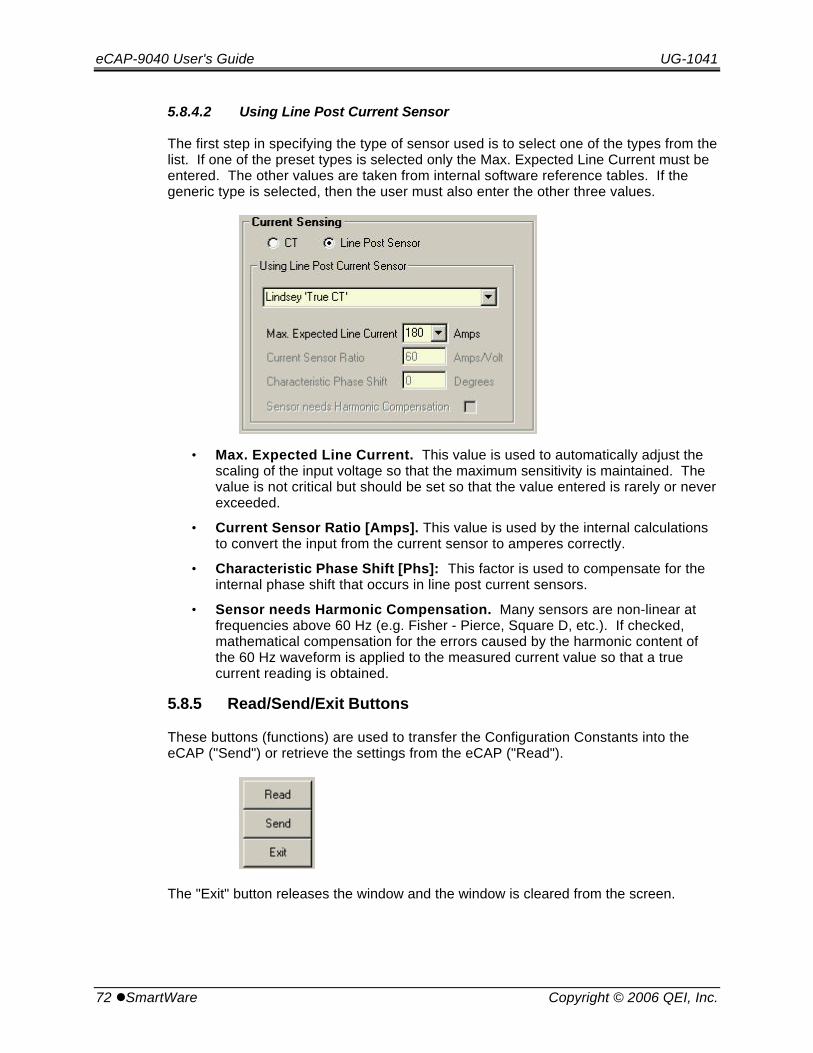
eCAP-9040 User's Guide UG-1041
72 lSmartWare Copyright © 2006 QEI, Inc.
5.8.4.2 Using Line Post Current Sensor
The first step in specifying the type of sensor used is to select one of the types from thelist. If one of the preset types is selected only the Max. Expected Line Current must beentered. The other values are taken from internal software reference tables. If thegeneric type is selected, then the user must also enter the other three values.
• Max. Expected Line Current. This value is used to automatically adjust thescaling of the input voltage so that the maximum sensitivity is maintained. Thevalue is not critical but should be set so that the value entered is rarely or neverexceeded.
• Current Sensor Ratio [Amps]. This value is used by the internal calculationsto convert the input from the current sensor to amperes correctly.
• Characteristic Phase Shift [Phs]: This factor is used to compensate for theinternal phase shift that occurs in line post current sensors.
• Sensor needs Harmonic Compensation. Many sensors are non-linear atfrequencies above 60 Hz (e.g. Fisher - Pierce, Square D, etc.). If checked,mathematical compensation for the errors caused by the harmonic content ofthe 60 Hz waveform is applied to the measured current value so that a truecurrent reading is obtained.
5.8.5 Read/Send/Exit Buttons
These buttons (functions) are used to transfer the Configuration Constants into theeCAP ("Send") or retrieve the settings from the eCAP ("Read").
The "Exit" button releases the window and the window is cleared from the screen.
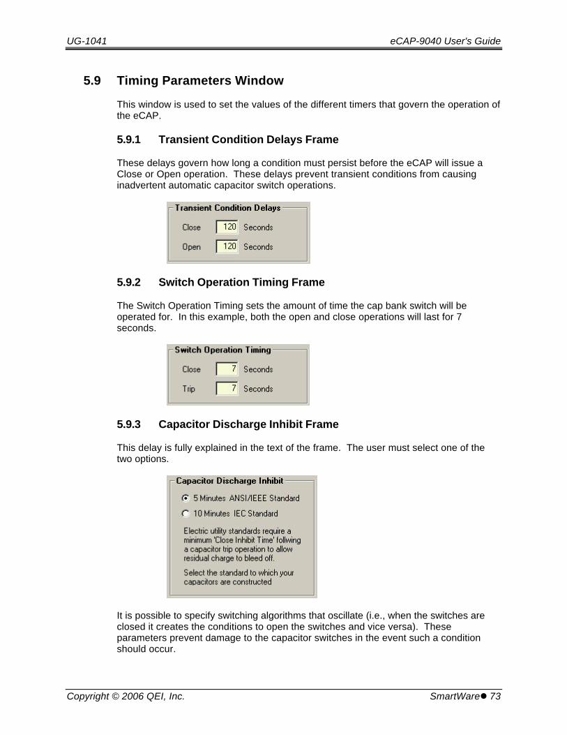
UG-1041 eCAP-9040 User's Guide
Copyright © 2006 QEI, Inc. SmartWarel 73
5.9 Timing Parameters Window
This window is used to set the values of the different timers that govern the operation ofthe eCAP.
5.9.1 Transient Condition Delays Frame
These delays govern how long a condition must persist before the eCAP will issue aClose or Open operation. These delays prevent transient conditions from causinginadvertent automatic capacitor switch operations.
5.9.2 Switch Operation Timing Frame
The Switch Operation Timing sets the amount of time the cap bank switch will beoperated for. In this example, both the open and close operations will last for 7seconds.
5.9.3 Capacitor Discharge Inhibit Frame
This delay is fully explained in the text of the frame. The user must select one of thetwo options.
It is possible to specify switching algorithms that oscillate (i.e., when the switches areclosed it creates the conditions to open the switches and vice versa). Theseparameters prevent damage to the capacitor switches in the event such a conditionshould occur.
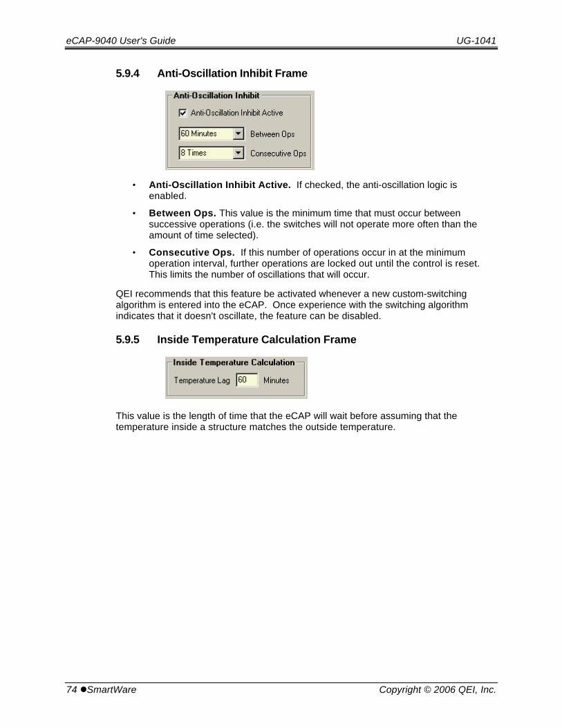
eCAP-9040 User's Guide UG-1041
74 lSmartWare Copyright © 2006 QEI, Inc.
5.9.4 Anti-Oscillation Inhibit Frame
• Anti-Oscillation Inhibit Active. If checked, the anti-oscillation logic isenabled.
• Between Ops. This value is the minimum time that must occur betweensuccessive operations (i.e. the switches will not operate more often than theamount of time selected).
• Consecutive Ops. If this number of operations occur in at the minimumoperation interval, further operations are locked out until the control is reset. This limits the number of oscillations that will occur.
QEI recommends that this feature be activated whenever a new custom-switchingalgorithm is entered into the eCAP. Once experience with the switching algorithmindicates that it doesn't oscillate, the feature can be disabled.
5.9.5 Inside Temperature Calculation Frame
This value is the length of time that the eCAP will wait before assuming that thetemperature inside a structure matches the outside temperature.

UG-1041 eCAP-9040 User's Guide
Copyright © 2006 QEI, Inc. SmartWarel 75
5.10 Holidays Window
The Holidays window is used to enter the holidays that the eCAP recognizes. This listcontains the holiday dates and the holiday day type that is associated with eachholiday. There is space in the holiday list for 50 holidays. Use the slider bar at theright of the list to view additional holidays.
• Date. The holiday is show in the following format: mm-dd-yy (where mm = a twocharacter month, dd = a two character day, and yy = a two character year).
• DOW. The day of the week (or day type) is entered as a single digit. There arethree digits set aside for holiday day types: (0, 8, and 9). Switching algorithmsto operate the control only on specific days or sets of days uses the day type. Permitting holiday day types to be both greater than ("8" and "9") and less than("0") the normal days allows a holiday to come before Monday (day type "1") orcome after "Sunday (day type "7"). Combining this with the less than "<" andgreater than ">" operators allows holidays to be classified with weekdays ("<6")or with weekends (">5"). Thus the assignment of holiday day types is notarbitrary.
Holidays may also be assigned to weekday day types (i.e., 1 - Monday through 7 -Sunday).
eCAP-9040 User's Guide UG-1041
76 lSmartWare Copyright © 2006 QEI, Inc.
5.10.1 Holidays List
Use the following procedure to modify an entry in the Holiday List or add a new holidayto the end of the list:
1. Select the entry to modify by placing the cursor anywhere on the entry andclicking.
2. The entry is highlighted and the entry data appears in the two data entryboxes at the bottom of the window.
3. Modify the data as desired using the two data entry boxes at the bottom ofthe window. As the data is modified, the altered data appears in theselected entry.
Use the following procedure to add an entry into the middle of the list:
1. Select the entry to follow the new entry by placing the cursor anywhere onthe entry and clicking.
2. Select the Insert button. Entries starting with the selected entry are moveddown one place leaving room for the new entry. (The newly created entry isnot highlighted even though it is selected.)
3. Modify the data as desired using the two data entry boxes at the bottom ofthe window. As the data is modified, the altered data appears in theselected entry.
Use the following procedure to remove an unwanted entry:
1. Select the entry to remove by placing the cursor anywhere on the entry andclicking. The entry is highlighted and the entry data appears in the two dataentry boxes at the bottom of the window.
2. Select the Delete button and the highlighted entry is removed and all of thesucceeding entries are move up one position.
3. The Read button retrieves the holiday list from the control and the "Send"downloads the holiday list from the computer into the eCAP.
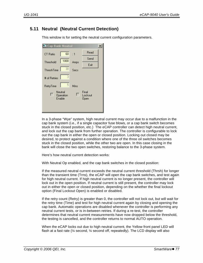
UG-1041 eCAP-9040 User's Guide
Copyright © 2006 QEI, Inc. SmartWarel 77
5.11 Neutral (Neutral Current Detection)
This window is for setting the neutral current configuration parameters.
In a 3-phase “Wye” system, high neutral current may occur due to a malfunction in thecap bank system (i.e., if a single capacitor fuse blows, or a cap bank switch becomesstuck in the closed position, etc.) The eCAP controller can detect high neutral current,and lock out the cap bank from further operation. The controller is configurable to lockout the cap bank in either the open or closed position. Locking out closed may bedesired, to protect against a condition where one of the three oil switches becomesstuck in the closed position, while the other two are open. In this case closing in thebank will close the two open switches, restoring balance to the 3-phase system.
Here’s how neutral current detection works:
With Neutral Op enabled, and the cap bank switches in the closed position:
If the measured neutral current exceeds the neutral current threshold (Thrsh) for longerthan the transient time (Trns), the eCAP will open the cap bank switches, and test againfor high neutral current. If high neutral current is no longer present, the controller willlock out in the open position. If neutral current is still present, the controller may lockout in either the open or closed position, depending on the whether the final lockoutoption (Final Lockout Open) is enabled or disabled.
If the retry count (Retry) is greater than 0, the controller will not lock out, but will wait forthe retry time (Time) and test for high neutral current again by closing and opening thecap bank. Automatic operations are disabled whenever the controller is performing anyneutral current tests, or is in-between retries. If during a re-test, the controllerdetermines that neutral current measurements have now dropped below the threshold,the testing is cancelled, and the controller returns to normal AUTO operation.
When the eCAP locks out due to high neutral current, the Yellow front panel LED willflash at a fast rate (¼ second, ¼ second off, repeatedly). The LCD display will also

eCAP-9040 User's Guide UG-1041
78 lSmartWare Copyright © 2006 QEI, Inc.
indicate the lock-out state. The LEDs do not flash between retries, only after thecontroller has locked-out.
Note that the eCAP may also lock-out due to excessive switching (Anti-Oscillation) suchas would occur if the Switching Algorithms or QuikStart voltage setpoints are setincorrectly. In this case, the LEDs will flash at a different rate (1 second on, 1 second offfor Anti-Oscillation), and the Display will indicate the lock-out cause.
In lock-out mode, all automatic operation is disabled.
To clear the lock-out mode, toggle the AUTO/MANUAL switch to MANUAL. After thecause of the lock-out has been corrected, set the switch back to AUTO again.
Configuration settings for Neutral Current Detection accessed via the Smartwaresoftware (Smartware/Setup/Neutral). The meaning of each configuration setting is asfollows:
CT Ratio - The CT ratio of the Neutral Current CT. The eCAP maximum NeutralCurrent CT input is 5 Amps (as measured on the CT secondary). Thus, a CT with aturns ratio of 60:1 would allow up to 300 Amp measurements. For example, to use a CTwith a ratio of 30:1, enter 30 in this field. The maximum measurable primary currentwould then be 150 Amps (150/30=5 Amps CT secondary). Range: 1:1 to 1000:1.
Threshold - Neutral Current Threshold. This sets the high neutral current detectionlevel. A neutral current measurement above this amount will cause the eCAP to indicatethat the threshold has been exceeded (the indication occurs on the SmartView screenand during SCADA communications) and operate the cap bank.
Range: 1 to 2000 Amps.
ThreshTime - Neutral Current Transient Time. To be considered as high neutralcurrent, the measurement must exceed the neutral current threshold for this amount oftime. This prevents transients from falsely triggering neutral current detection. Range: 1to 18000 seconds.
# of Retries - The eCAP will re-test for high neutral current for this number of timesbefore locking out. Set this number to 0 if retries are not required. Range: 0 to 999retries.
RetryTime - Time in minutes to wait between retries. Range: 1 to 32767 minutes.
Neutral Operation Enable - This setting enables or disables neutral currentdetection. If checked, neutral current detection is enabled.
Final Lockout Open - This is the final lockout mode. If enabled, the eCAP will alwayslock-out the cap bank in the open state, if high neutral current is detected.
If disabled, the eCAP will lock out the cap bank as follows:
1) High neutral current detected when switches are closed, and normal neutralcurrent when switches are open (as might be the case if a capacitor fuse isblown): lock-out with the cap bank in the OPEN position.

UG-1041 eCAP-9040 User's Guide
Copyright © 2006 QEI, Inc. SmartWarel 79
2) High neutral current detected when switches are open, and normal neutralcurrent when switches are closed (as might be the case if a capacitor bankswitch was stuck in the closed position): lock-out the cap bank in the CLOSEDposition to maintain system balance.
3) High neutral current detected when switches are OPEN, and high neutralcurrent when switches are closed: (as might be the case if both of the aboveconditions occurred): lock-out the cap bank in the CLOSED position.

eCAP-9040 User's Guide UG-1041
80 lSmartWare Copyright © 2006 QEI, Inc.
5.12 Identification Window
There are two frames in this window: the SmartMemo frame and the Unit ID frame. TheSmartMemo is used to enter a short message that is stored in the eCAP. This memo isavailable for whatever use the operator/user wishes. The Unit ID Number is theidentification number of the unit. This frame is used to view or change the eCAP unit IDnumber.
5.12.1 Unit Id Number
• Present ID. This is the ID number of the attached eCAP.
• Change to. This box is used to change the ID number of the eCAP. Thenumber entered into this box is downloaded into the eCAP when the "Send"button is pressed. It then appears in the "Present ID" box.
5.13 SmartMemo
• Present Text. This is the memo that is currently stored in the attached eCAP.
• Change to. This entry box is used to change the memo text. Text entered intothis box is downloaded into the eCAP when the "Send" button is pressed. Itthen appears in the "Present Text" box.
5.14 Temperature Units
When this menu item is selected, as submenu appears with one of its two entrieschecked. This is the temperature units (or scale) that are currently active. To changeto the temperature scale, check the desired temperature scale to select it. When adifferent temperature scale is checked, the previous one is unchecked.

UG-1041 eCAP-9040 User's Guide
Copyright © 2006 QEI, Inc. SmartWarel 81
5.15 Calibration
The eCAP voltage and current measurement circuitry is factory calibrated and shouldnot be adjusted in the field. Changes to the calibration may adversely affect theperformance of the eCAP. If calibration is required, contact the factory for furtherinformation.
5.16 Reset
This feature resets all configuration settings to default values. Factory calibrationinformation is retained. QEI does not recommend using this feature until the user isthoroughly familiar with the operation of the eCAP and the purpose all configurationsettings.
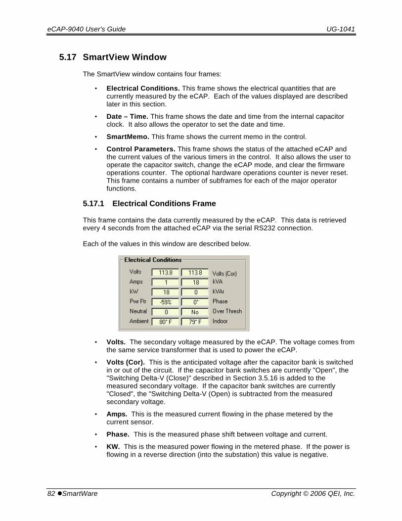
eCAP-9040 User's Guide UG-1041
82 lSmartWare Copyright © 2006 QEI, Inc.
5.17 SmartView Window
The SmartView window contains four frames:
• Electrical Conditions. This frame shows the electrical quantities that arecurrently measured by the eCAP. Each of the values displayed are describedlater in this section.
• Date – Time. This frame shows the date and time from the internal capacitorclock. It also allows the operator to set the date and time.
• SmartMemo. This frame shows the current memo in the control.
• Control Parameters. This frame shows the status of the attached eCAP andthe current values of the various timers in the control. It also allows the user tooperate the capacitor switch, change the eCAP mode, and clear the firmwareoperations counter. The optional hardware operations counter is never reset. This frame contains a number of subframes for each of the major operatorfunctions.
5.17.1 Electrical Conditions Frame
This frame contains the data currently measured by the eCAP. This data is retrievedevery 4 seconds from the attached eCAP via the serial RS232 connection.
Each of the values in this window are described below.
• Volts. The secondary voltage measured by the eCAP. The voltage comes fromthe same service transformer that is used to power the eCAP.
• Volts (Cor). This is the anticipated voltage after the capacitor bank is switchedin or out of the circuit. If the capacitor bank switches are currently "Open", the"Switching Delta-V (Close)" described in Section 3.5.16 is added to themeasured secondary voltage. If the capacitor bank switches are currently"Closed", the "Switching Delta-V (Open) is subtracted from the measuredsecondary voltage.
• Amps. This is the measured current flowing in the phase metered by thecurrent sensor.
• Phase. This is the measured phase shift between voltage and current.
• KW. This is the measured power flowing in the metered phase. If the power isflowing in a reverse direction (into the substation) this value is negative.
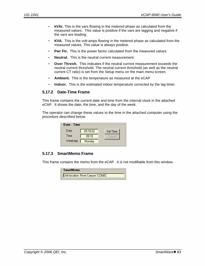
UG-1041 eCAP-9040 User's Guide
Copyright © 2006 QEI, Inc. SmartWarel 83
• kVAr. This is the vars flowing in the metered phase as calculated from themeasured values. This value is positive if the vars are lagging and negative ifthe vars are leading.
• KVA. This is the volt-amps flowing in the metered phase as calculated from themeasured values. This value is always positive.
• Pwr Ftr. This is the power factor calculated from the measured values.
• Neutral. This is the neutral current measurement.
• Over Thresh. This indicates if the neutral current measurement exceeds theneutral current threshold. The neutral current threshold (as well as the neutralcurrent CT ratio) is set from the Setup menu on the main menu screen.
• Ambient. This is the temperature as measured at the eCAP
• Indoor. This is the estimated indoor temperature corrected by the lag timer.
5.17.2 Date-Time Frame
This frame contains the current date and time from the internal clock in the attachedeCAP. It shows the date, the time, and the day of the week.
The operator can change these values to the time in the attached computer using theprocedure described below.
5.17.3 SmartMemo Frame
This frame contains the memo from the eCAP. It is not modifiable from this window.

eCAP-9040 User's Guide UG-1041
84 lSmartWare Copyright © 2006 QEI, Inc.
5.17.4 Control Parameters Frame
This frame contains five subframes that contain the status of the attached eCAP. Thebuttons in these subframes are also used to control the capacitor bank switches, modifythe operating mode of the eCAP, or clear the internal firmware operation count. Eachof the subframes is described below. The operations possible via these subframes isdescribed in the following section.
5.17.4.1 Operating Mode
This frame shows the operating mode of the attached eCAP. The mode of the eCAPdetermines how it operates. The three modes available from the "SmartWare" programare described below.
• Auto. When an eCAP is in "Auto" mode, the control is using the switchingalgorithm to decide when to open and close the capacitor bank switches.
• Test. Anti-oscillation timer changed to 40 sec. After 5 min inactivity reverts tonormal auto operation. Used for testing the algorithm.
• Remote. When an eCAP is in "Remote" mode, the control accepts commandfrom the attached computer to operate the capacitor bank switches. If a eCAPis placed in Remote mode, it will remain in remote mode when the computer isdisconnected from the control and can only be removed from Remote mode byreattaching a computer and changing the mode to "Auto".
5.17.4.2 Switch Status
This frame shows the current state of the capacitor bank switches. Operation of thecapacitor bank switches is described in the next section.
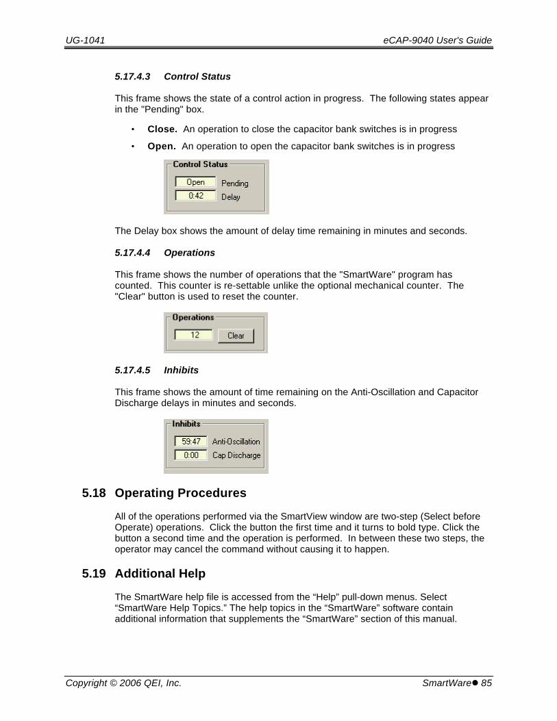
UG-1041 eCAP-9040 User's Guide
Copyright © 2006 QEI, Inc. SmartWarel 85
5.17.4.3 Control Status
This frame shows the state of a control action in progress. The following states appearin the "Pending" box.
• Close. An operation to close the capacitor bank switches is in progress
• Open. An operation to open the capacitor bank switches is in progress
The Delay box shows the amount of delay time remaining in minutes and seconds.
5.17.4.4 Operations
This frame shows the number of operations that the "SmartWare" program hascounted. This counter is re-settable unlike the optional mechanical counter. The"Clear" button is used to reset the counter.
5.17.4.5 Inhibits
This frame shows the amount of time remaining on the Anti-Oscillation and CapacitorDischarge delays in minutes and seconds.
5.18 Operating Procedures
All of the operations performed via the SmartView window are two-step (Select beforeOperate) operations. Click the button the first time and it turns to bold type. Click thebutton a second time and the operation is performed. In between these two steps, theoperator may cancel the command without causing it to happen.
5.19 Additional Help
The SmartWare help file is accessed from the “Help” pull-down menus. Select“SmartWare Help Topics.” The help topics in the “SmartWare” software containadditional information that supplements the “SmartWare” section of this manual.

eCAP-9040 User's Guide UG-1041
86 lSCADA Communications Copyright © 2006 QEI, Inc.
6. SCADA Communications
6.1 Installing a Radio
The illustration below shows the relevant components of a typical completed radioinstallation in the eCAP. The sections to follow provide further details:
Note that the radio, antenna, and antenna cabling are not supplied by QEI. Note theorientation of the DB9 (or DB25) RS-232 cable, DC power, antenna, and antennacabling. This illustration shows the suggested routing for these cables.

UG-1041 eCAP-9040 User's Guide
Copyright © 2006 QEI, Inc. SCADA Communicationsl 87
6.1.1 Universal Radio Mounting Plate
Each eCAP unit contains a removable plate that can be used to mount the data radio,modem, etc. to the eCAP chassis. The plate can be removed by loosening the fourscrews securing it to the chassis. The plate can then be drilled to match the mountingradio mounting footprint. The radio is then secured to the plate and the plate/radiocombination is then reinstalled in the eCAP.
6.2 Radio Power Supply
The eCAP is equipped with a power supply for powering the data-radio, modem, etc.The power supply has a +12Vdc output, which is rated for approx 2.5 Amps. The powersupply DC output wiring is left un-terminated in the eCAP enclosure, and can beterminated to suit the existing communications equipment. Red wire = +12Vdc, Blackwire = common. See illustrations on the following pages.
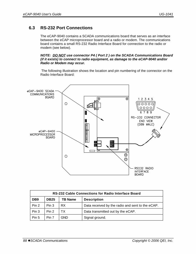
eCAP-9040 User's Guide UG-1041
88 lSCADA Communications Copyright © 2006 QEI, Inc.
6.3 RS-232 Port Connections
The eCAP-9040 contains a SCADA communications board that serves as an interfacebetween the eCAP microprocessor board and a radio or modem. The communicationsboard contains a small RS-232 Radio Interface Board for connection to the radio ormodem (see below).
NOTE: DO NOT use connector P4 ( Port 2 ) on the SCADA Communications Board(if it exists) to connect to radio equipment, as damage to the eCAP-9040 and/orRadio or Modem may occur.
The following illustration shows the location and pin numbering of the connector on theRadio Interface Board:
RS-232 Cable Connections for Radio Interface Board
DB9 DB25 TB Name Description
Pin 2 Pin 3 RX Data received by the radio and sent to the eCAP.
Pin 3 Pin 2 TX Data transmitted out by the eCAP.
Pin 5 Pin 7 GND Signal ground.
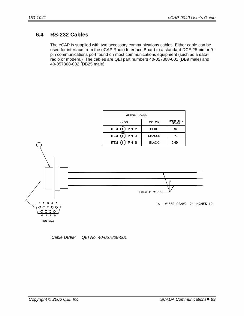
UG-1041 eCAP-9040 User's Guide
Copyright © 2006 QEI, Inc. SCADA Communicationsl 89
6.4 RS-232 Cables
The eCAP is supplied with two accessory communications cables. Either cable can beused for interface from the eCAP Radio Interface Board to a standard DCE 25-pin or 9-pin communications port found on most communications equipment (such as a data-radio or modem.) The cables are QEI part numbers 40-057808-001 (DB9 male) and40-057808-002 (DB25 male).
Cable DB9M QEI No. 40-057808-001
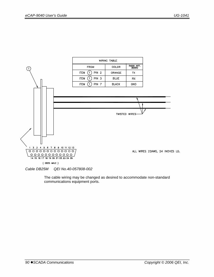
eCAP-9040 User's Guide UG-1041
90 lSCADA Communications Copyright © 2006 QEI, Inc.
Cable DB25M QEI No.40-057808-002
The cable wiring may be changed as desired to accommodate non-standardcommunications equipment ports.
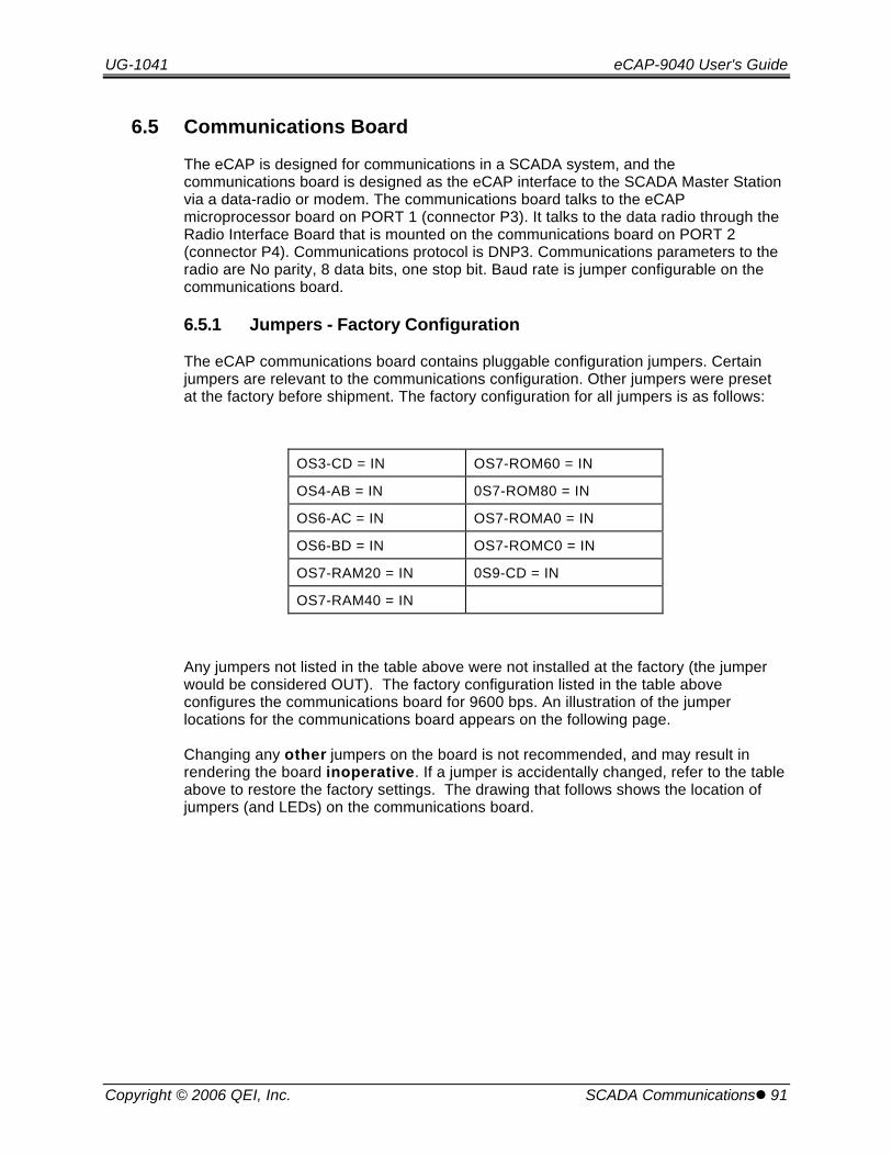
UG-1041 eCAP-9040 User's Guide
Copyright © 2006 QEI, Inc. SCADA Communicationsl 91
6.5 Communications Board
The eCAP is designed for communications in a SCADA system, and thecommunications board is designed as the eCAP interface to the SCADA Master Stationvia a data-radio or modem. The communications board talks to the eCAPmicroprocessor board on PORT 1 (connector P3). It talks to the data radio through theRadio Interface Board that is mounted on the communications board on PORT 2(connector P4). Communications protocol is DNP3. Communications parameters to theradio are No parity, 8 data bits, one stop bit. Baud rate is jumper configurable on thecommunications board.
6.5.1 Jumpers - Factory Configuration
The eCAP communications board contains pluggable configuration jumpers. Certainjumpers are relevant to the communications configuration. Other jumpers were presetat the factory before shipment. The factory configuration for all jumpers is as follows:
OS3-CD = IN OS7-ROM60 = IN
OS4-AB = IN 0S7-ROM80 = IN
OS6-AC = IN OS7-ROMA0 = IN
OS6-BD = IN OS7-ROMC0 = IN
OS7-RAM20 = IN 0S9-CD = IN
OS7-RAM40 = IN
Any jumpers not listed in the table above were not installed at the factory (the jumperwould be considered OUT). The factory configuration listed in the table aboveconfigures the communications board for 9600 bps. An illustration of the jumperlocations for the communications board appears on the following page.
Changing any other jumpers on the board is not recommended, and may result inrendering the board inoperative. If a jumper is accidentally changed, refer to the tableabove to restore the factory settings. The drawing that follows shows the location ofjumpers (and LEDs) on the communications board.
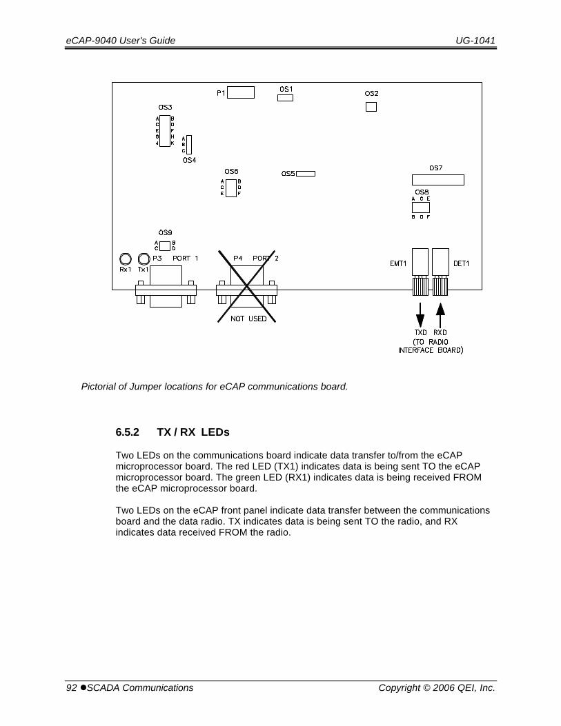
eCAP-9040 User's Guide UG-1041
92 lSCADA Communications Copyright © 2006 QEI, Inc.
Pictorial of Jumper locations for eCAP communications board.
6.5.2 TX / RX LEDs
Two LEDs on the communications board indicate data transfer to/from the eCAPmicroprocessor board. The red LED (TX1) indicates data is being sent TO the eCAPmicroprocessor board. The green LED (RX1) indicates data is being received FROMthe eCAP microprocessor board.
Two LEDs on the eCAP front panel indicate data transfer between the communicationsboard and the data radio. TX indicates data is being sent TO the radio, and RXindicates data received FROM the radio.

UG-1041 eCAP-9040 User's Guide
Copyright © 2006 QEI, Inc. SCADA Communicationsl 93
6.5.3 Setting the Baud Rate
Use jumper OS3 to change the baud rate.
The communications board is configurable for the following baud rates: 1200, 2400,4800, 9600, 19200. Baud rate is configured via pluggable jumpers. For all baud rates,insure that jumper OS4-AB is IN, while jumper OS4-BC is OUT. Otherwise, none of thebaud rates will function correctly.
Factory default for the jumper OS3 is CD = IN = 9600 baud. Refer to the following tableto configure jumper OS3 for the required baud rate:
BAUD RATE JUMPERS
1200 2400 4800 9600 19200
OS3-JK IN OUT OUT OUT OUT
OS3-GH OUT IN OUT OUT OUT
OS3-EF OUT OUT IN OUT OUT
OS3-CD OUT OUT OUT IN OUT
OS3-AB OUT OUT OUT OUT IN
6.6 Radio Interface BoardThe RS-232 Radio Interface Board provides an isolated RS-232 interface between the SCADACommunications Board and the data radio:
eCAP CPUBOARD
SCADA COMMBOARD
RS-232 RADIO INTFACE BD DATA RADIO
FIBEROPTICAL
RS-232
ANTENNA
(CUSTOMER SUPPLIED)
eCAP-9040 User's Guide UG-1041
94 lSCADA Communications Copyright © 2006 QEI, Inc.
The Radio Interface Board contains a 4 position terminal block (J1) for connection ofthe above RS-232 data cables. The board is marked next to the terminal block with thelegends “RX”, “TX”, “+12V”, and “GND”:
RADIO INTERFACE
BOARD, J1TERMINAL BLOCK
CONNECTEDWIRE
COLOR
DESCRIPTION
RX BLUE Incoming data from the radioTX ORANGE Outgoing data transmitted by the
eCAP+12V RED Power (from radio power supply)GND BLACK Power supply return, and data
common.
The drawing below shows a closeup view of the Radio Interface Board:
The jumpers for JP1 must always be oriented as shown in the Radio Interface Board drawingabove (the jumpers are parallel to the “long” side of this board as shown). The Radio InterfaceBoard part number is 40-057807-001.
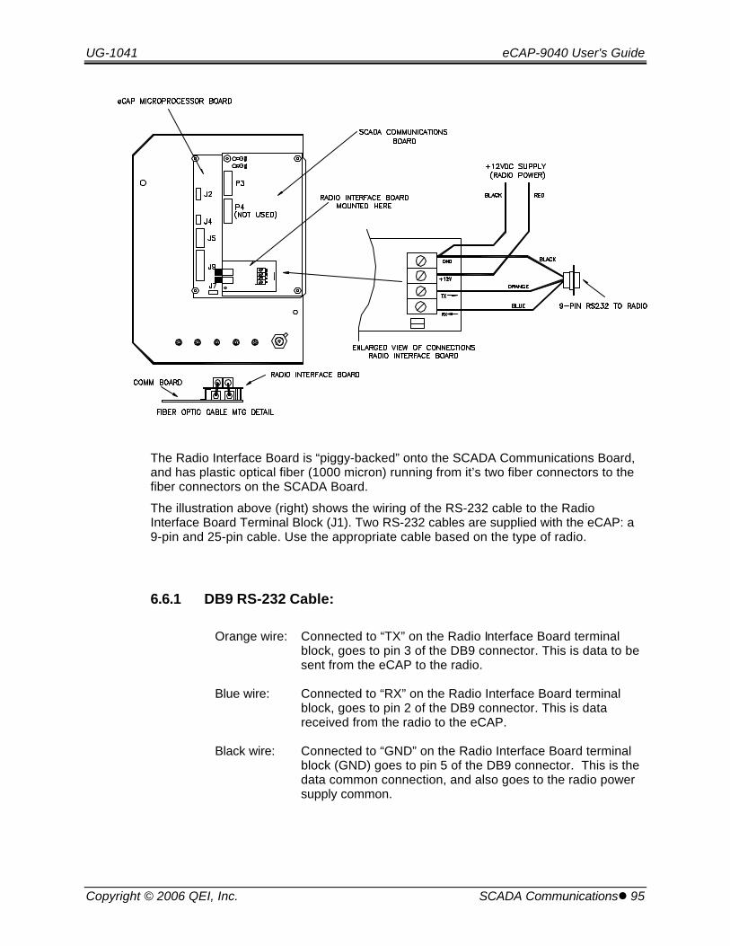
UG-1041 eCAP-9040 User's Guide
Copyright © 2006 QEI, Inc. SCADA Communicationsl 95
The Radio Interface Board is “piggy-backed” onto the SCADA Communications Board,and has plastic optical fiber (1000 micron) running from it’s two fiber connectors to thefiber connectors on the SCADA Board.
The illustration above (right) shows the wiring of the RS-232 cable to the RadioInterface Board Terminal Block (J1). Two RS-232 cables are supplied with the eCAP: a9-pin and 25-pin cable. Use the appropriate cable based on the type of radio.
6.6.1 DB9 RS-232 Cable:
Orange wire: Connected to “TX” on the Radio Interface Board terminalblock, goes to pin 3 of the DB9 connector. This is data to besent from the eCAP to the radio.
Blue wire: Connected to “RX” on the Radio Interface Board terminalblock, goes to pin 2 of the DB9 connector. This is datareceived from the radio to the eCAP.
Black wire: Connected to “GND” on the Radio Interface Board terminalblock (GND) goes to pin 5 of the DB9 connector. This is thedata common connection, and also goes to the radio powersupply common.
eCAP-9040 User's Guide UG-1041
96 lSCADA Communications Copyright © 2006 QEI, Inc.
6.6.2 DB25 RS-232 Cable:
Orange wire: Connected to “TX” on the Radio Interface Board terminalblock, goes to pin 2 of the DB25 connector. This is data tobe sent from the eCAP to the radio.
Blue wire: Connected to “RX” on the Radio Interface Board terminalblock, goes to pin 3 of the DB25 connector. This is datareceived from the radio to the eCAP.
Black wire: Connected to “GND” on the Radio Interface Board terminalblock, goes to pin 7 of the DB25 connector. This is the datacommon connection, and also goes to the radio powersupply common.
6.7 Antenna
A suggested antenna location is shown below. When mounting the antenna, make surethe location provides clearance for any internal parts of the eCAP, and that the locationdoes not interfere with the circuit boards or other equipment inside, when the frontpanel is closed/opened.
The antenna will also require a metal backing plate to serve as a ground plane, forreliable communication.

UG-1041 eCAP-9040 User's Guide
Copyright © 2006 QEI, Inc. SCADA Override (optional)l 97
6.8 Local/Remote Front Panel Switch
In order to use SCADA communications, the front panel LOCAL/REMOTE switch mustbe in the REMOTE position. When in the REMOTE position, the eCAP communicateswith a SCADA system using a data radio or modem, etc. When the switch is in theLOCAL position, the eCAP communicates with a Laptop PC through the RS-232 port onthe front panel. The PC must be running QEI’s “SmartWare” software. Note that whenthe switch is in REMOTE position, the front panel RS-232 port is disabled, and when itis in LOCAL position, SCADA communications via data radio is disabled.
7. SCADA Override (optional)
For Undervoltage and Overvoltage Conditions
7.1 Introduction
The eCAP has two distinct operating modes that are accessed via DNP Control Point#1. They are REMOTE and AUTO mode.

eCAP-9040 User's Guide UG-1041
98 lSCADA Override (optional) Copyright © 2006 QEI, Inc.
When the eCAP is in REMOTE mode, it will be under SCADA control and responds tocommands from the SCADA Master Station. The local Algorithms do not function in thismode.
When the eCAP is in AUTO mode, it opens or closes the cap bank automatically basedon its’ locally programmed Algorithms, and ignores commands from the SCADA MasterStation to open or close the cap bank.
A third mode is available, which combines the REMOTE mode with the local Algorithmsto override the SCADA control if the voltage falls too low, or if the voltage rises too high.This feature is termed “Undervoltage/Overvoltage SCADA Override”.
This feature is enabled via DNP, and is used in conjunction with REMOTE mode. Withthe eCAP in REMOTE mode (under SCADA control), if the voltage falls too low the capbank will close, and if the voltage rises too high, the cap bank will open, regardless ofwhat the SCADA system requests. Once the voltage returns to an acceptable level,control is handed back to the SCADA system.
In order for this feature to function correctly, the local Algorithms must be programmedin a precise format.
UG-1041 eCAP-9040 User's Guide
Copyright © 2006 QEI, Inc. SCADA Override (optional)l 99
7.2 Relevant DNP Points
The following DNP points are applicable to the “Undervoltage/Overvoltage SCADAOverride” feature. Please also see the DNP Point Listing (section 8.0 of this manual):
Point Type Addr Description
Control Point #1 REMOTE / AUTO Mode. When set to REMOTEMode, with Control Point #6 enabled (see below), theeCAP will be under SCADA control, however, theeCAP Algorithms will function to override SCADA (forundervoltage and overvoltage conditions only).When set to AUTO Mode, SCADA operation isdisabled, and the Algorithms will then function toautomatically switch the bank locally, without SCADAcontrol.
Control Point #6 SCADA Override Enable/Disable. This pointactivates the SCADA override feature.
Status Point #9 “SCADA Override Feature Enabled/Disabled”Status. This point indicates the status of theOverride feature (enabled or disabled).
Status Point #10 “SCADA Override Active” Flag. When the eCAPdetects an under or over voltage condition, it willoverride SCADA and close or open the bank asappropriate, while indicating the override conditionthrough Status Point #10. When voltage returns toan acceptable level, Status point #10 isautomatically cleared.
eCAP-9040 User's Guide UG-1041
100 lSCADA Override (optional) Copyright © 2006 QEI, Inc.
7.3 Algorithm Programming Considerations
7.3.1 “VCor” and “Learn Mode”
For SCADA Undervoltage / Overvoltage Override to function correctly, the Algorithmsmust be entered in an exact format (more on this in Section 7.4 “Algorithms”). TheSCADA override Algorithms make use of the “VCor” Algorithm parameter. The followinginformation is intended to provide a better understanding of the VCor parameter.Additional information on “VCor” is provided in section 3 of this guide.
“VCor” is a predictive value of the voltage rise when the cap bank is closed, and thevoltage drop when the cap bank opens.
For example, say that the voltage will rise and drop by 1.5 Volts as the cap bank opensand closes. Also, assume that the cap bank switches are in the open position, and themeasured line Voltage is 117.5 Volts.
With Switches in the Open position:
VCor = Measured Voltage + Predicted Rise = 117.5 + 1.5 = 119.0 Volts
Assume that the switches now close:
With Switches in the Closed position:
VCor = Measured Voltage + Predicted Drop = 119.0 -1.5 = 117.5 Volts
The Algorithms make use of VCor to set up voltage “Guarding”. That is, if the switchesare open, VCor can be used to prevent the switches from closing if doing so wouldcause the voltage to rise too high, and prevent the switches from opening, if doing sowould cause the voltage to fall too low.
The SmartWare Hardware Configuration “Switching delta-V” has a check box called“Learn Mode”, which can also be set through the eCAP front panel LCD from the“Switching V-Hyst” menu display. When this feature is enabled, the eCAP will learn whatthe predicted voltage rise and drop should be (averaged typically over four operationsor so), and will automatically apply it to the VCor calculations.
The predicted voltage rise and drop can also be entered into the eCAP through theSmartWare configuration software, under “Hardware Configuration”, using the“Switching delta-V” sliders. The “Close” slider is used to set the predicted voltage riseafter closing. The “Open” slider is used to set the predicted voltage drop after opening.These values can also be set through the eCAP front panel LCD from the “Switching V-Hyst” menu display.
If the voltage rise and drop is typically half a volt (.5 volt) or greater, then “Learn” Modecan be enabled. For voltage rise and drops that are typically less than this (forexample, .4 Volts or less) better results may be achieved by disabling “Learn” Mode,and entering the rise and drop manually.
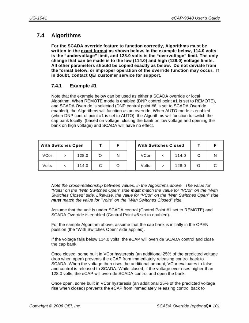
UG-1041 eCAP-9040 User's Guide
Copyright © 2006 QEI, Inc. SCADA Override (optional)l 101
7.4 Algorithms
For the SCADA override feature to function correctly, Algorithms must bewritten in the exact format as shown below. In the example below, 114.0 voltsis the “undervoltage” limit, and 128.0 volts is the “overvoltage” limit. The onlychange that can be made is to the low (114.0) and high (128.0) voltage limits.All other parameters should be copied exactly as below. Do not deviate fromthe format below, or improper operation of the override function may occur. Ifin doubt, contact QEI customer service for support.
7.4.1 Example #1
Note that the example below can be used as either a SCADA override or localAlgorithm. When REMOTE mode is enabled (DNP control point #1 is set to REMOTE),and SCADA Override is selected (DNP control point #6 is set to SCADA Overrideenabled), the Algorithms will function as an override. When AUTO mode is enabled(when DNP control point #1 is set to AUTO), the Algorithms will function to switch thecap bank locally, (based on voltage, closing the bank on low voltage and opening thebank on high voltage) and SCADA will have no effect.
With Switches Open T F With Switches Closed T F
VCor > 128.0 O N VCor < 114.0 C N
Volts < 114.0 C O Volts > 128.0 O C
Note the cross-relationship between values, in the Algorithms above. The value for“Volts” on the “With Switches Open” side must match the value for “VCor” on the “WithSwitches Closed” side. Likewise, the value for “VCor” on the “With Switches Open” sidemust match the value for “Volts” on the “With Switches Closed” side.
Assume that the unit is under SCADA control (Control Point #1 set to REMOTE) andSCADA Override is enabled (Control Point #6 set to enabled).
For the sample Algorithm above, assume that the cap bank is initially in the OPENposition (the “With Switches Open” side applies).
If the voltage falls below 114.0 volts, the eCAP will override SCADA control and closethe cap bank.
Once closed, some built in VCor hysteresis (an additional 25% of the predicted voltagedrop when open) prevents the eCAP from immediately releasing control back toSCADA. When the voltage then rises the additional amount, VCor evaluates to false,and control is released to SCADA. While closed, if the voltage ever rises higher than128.0 volts, the eCAP will override SCADA control and open the bank.
Once open, some built in VCor hysteresis (an additional 25% of the predicted voltagerise when closed) prevents the eCAP from immediately releasing control back to
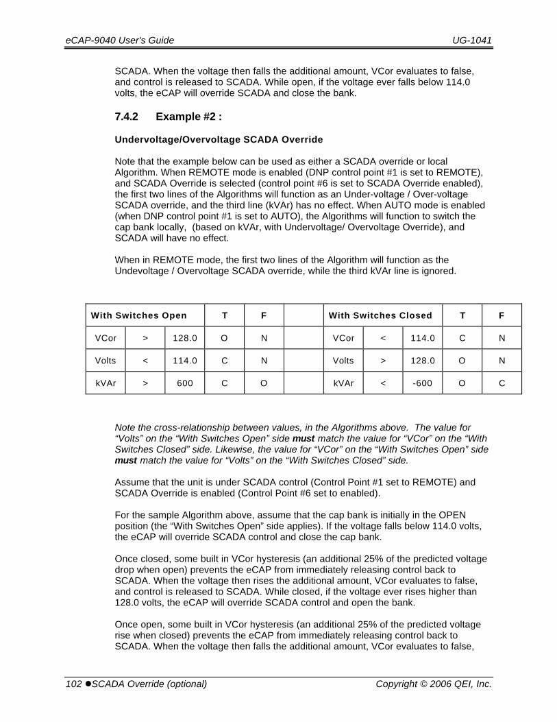
eCAP-9040 User's Guide UG-1041
102 lSCADA Override (optional) Copyright © 2006 QEI, Inc.
SCADA. When the voltage then falls the additional amount, VCor evaluates to false,and control is released to SCADA. While open, if the voltage ever falls below 114.0volts, the eCAP will override SCADA and close the bank.
7.4.2 Example #2 :
Undervoltage/Overvoltage SCADA Override
Note that the example below can be used as either a SCADA override or localAlgorithm. When REMOTE mode is enabled (DNP control point #1 is set to REMOTE),and SCADA Override is selected (control point #6 is set to SCADA Override enabled),the first two lines of the Algorithms will function as an Under-voltage / Over-voltageSCADA override, and the third line (kVAr) has no effect. When AUTO mode is enabled(when DNP control point #1 is set to AUTO), the Algorithms will function to switch thecap bank locally, (based on kVAr, with Undervoltage/ Overvoltage Override), andSCADA will have no effect.
When in REMOTE mode, the first two lines of the Algorithm will function as theUndevoltage / Overvoltage SCADA override, while the third kVAr line is ignored.
With Switches Open T F With Switches Closed T F
VCor > 128.0 O N VCor < 114.0 C N
Volts < 114.0 C N Volts > 128.0 O N
kVAr > 600 C O kVAr < -600 O C
Note the cross-relationship between values, in the Algorithms above. The value for“Volts” on the “With Switches Open” side must match the value for “VCor” on the “WithSwitches Closed” side. Likewise, the value for “VCor” on the “With Switches Open” sidemust match the value for “Volts” on the “With Switches Closed” side.
Assume that the unit is under SCADA control (Control Point #1 set to REMOTE) andSCADA Override is enabled (Control Point #6 set to enabled).
For the sample Algorithm above, assume that the cap bank is initially in the OPENposition (the “With Switches Open” side applies). If the voltage falls below 114.0 volts,the eCAP will override SCADA control and close the cap bank.
Once closed, some built in VCor hysteresis (an additional 25% of the predicted voltagedrop when open) prevents the eCAP from immediately releasing control back toSCADA. When the voltage then rises the additional amount, VCor evaluates to false,and control is released to SCADA. While closed, if the voltage ever rises higher than128.0 volts, the eCAP will override SCADA control and open the bank.
Once open, some built in VCor hysteresis (an additional 25% of the predicted voltagerise when closed) prevents the eCAP from immediately releasing control back toSCADA. When the voltage then falls the additional amount, VCor evaluates to false,

UG-1041 eCAP-9040 User's Guide
Copyright © 2006 QEI, Inc. SCADA Override (optional)l 103
and control is released to SCADA. While open, if the voltage ever falls below 114.0volts, the eCAP will override SCADA and close the bank.
If additional assistance with the SCADA Undervoltage/Overvoltage override function,please contact QEI customer service.
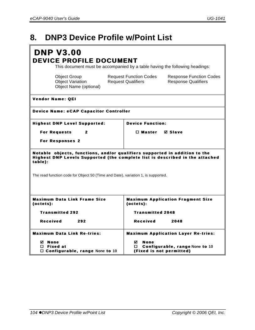
eCAP-9040 User's Guide UG-1041
104 lDNP3 Device Profile w/Point List Copyright © 2006 QEI, Inc.
8. DNP3 Device Profile w/Point List
DNP V3.00DNP V3.00DEVICE PROFILE DOCUMENTDEVICE PROFILE DOCUMENT
This document must be accompanied by a table having the following headings:
Object Group Request Function Codes Response Function CodesObject Variation Request Qualifiers Response QualifiersObject Name (optional)
V e n d o r N a m e : Q E IV e n d o r N a m e : Q E I
D e v i c e N a m e : e C A P C a p a c i t o r C o n t r o l l e rD e v i c e N a m e : e C A P C a p a c i t o r C o n t r o l l e r
H i g h e s t D N P L e v e l S u p p o r t e d :H i g h e s t D N P L e v e l S u p p o r t e d :
F o r R e q u e s t sF o r R e q u e s t s 22
F o r R e s p o n s e sF o r R e s p o n s e s 22
D e v i c e F u n c t i o n : D e v i c e F u n c t i o n :
¨̈ M a s t e r M a s t e r þþ S l a v e S l a v e
N o t a b l e o b j e c t s , f u n c t i o n s , a n d / o r q u a l i f i e r s s u p p o r t e d i n a d d i t i o n t o t h eN o t a b l e o b j e c t s , f u n c t i o n s , a n d / o r q u a l i f i e r s s u p p o r t e d i n a d d i t i o n t o t h eH i g h e s t D N P L e v e l s S u p p o r t e d ( t h e c o m p l e t e l i s t i s d e s c r i b e d i n t h e a t t a c h e dH i g h e s t D N P L e v e l s S u p p o r t e d ( t h e c o m p l e t e l i s t i s d e s c r i b e d i n t h e a t t a c h e dt a b l e ) :t a b l e ) :
The read function code for Object 50 (Time and Date), variation 1, is supported.
M a x i m u m D a t a L i n k F r a m e S i z eM a x i m u m D a t a L i n k F r a m e S i z e( o c t e t s ) :( o c t e t s ) :
T r a n s m i t t e dT r a n s m i t t e d 2 9 22 9 2
R e c e i v e dR e c e i v e d 2 9 22 9 2
M a x i m u m A p p l i c a t i o n F r a g m e n t S i z eM a x i m u m A p p l i c a t i o n F r a g m e n t S i z e( o c t e t s ) :( o c t e t s ) :
T r a n s m i t t e dT r a n s m i t t e d 2 0 4 82 0 4 8
R e c e i v e dR e c e i v e d 2 0 4 82 0 4 8
M a x i m u m D a t a L i n k R e - t r i e s :M a x i m u m D a t a L i n k R e - t r i e s :
þþ N o n e N o n e¨̈ F i x e d a t F i x e d a t¨̈ C o n f i g u r a b l e , r a n g e C o n f i g u r a b l e , r a n g e None t o t o 10
M a x i m u m A p p l i c a t i o n L a y e r R e - t r i e s :M a x i m u m A p p l i c a t i o n L a y e r R e - t r i e s :
þþ N o n eN o n e¨ ¨ C o n f i g u r a b l e , r a n g eC o n f i g u r a b l e , r a n g e None t o t o 10( F i x e d i s n o t p e r m i t t e d )( F i x e d i s n o t p e r m i t t e d )

UG-1041 eCAP-9040 User's Guide
Copyright © 2006 QEI, Inc. DNP3 Device Profile w/Point Listl 105
R e q u i r e s D a t a L i n k L a y e r C o n f i r m a t i o n :R e q u i r e s D a t a L i n k L a y e r C o n f i r m a t i o n :
þþ N e v e r N e v e r¨̈ A l w a y s A l w a y s¨̈ S o m e t i m e s : F o r m u l t i - f r a m e m e s s a g e s . S o m e t i m e s : F o r m u l t i - f r a m e m e s s a g e s . ¨̈ C o n f i g u r a b l e C o n f i g u r a b l e
R e q u i r e s A p p l i c a t i o n L a y e r C o n f i r m a t i o n :R e q u i r e s A p p l i c a t i o n L a y e r C o n f i r m a t i o n :
¨̈ N e v e r N e v e r¨̈ A l w a y s ( n o t r e c o m m e n d e d ) A l w a y s ( n o t r e c o m m e n d e d )þþ W h e n r e p o r t i n g E v e n t D a t a ( S l a v e d e v i c e s o n l y ) W h e n r e p o r t i n g E v e n t D a t a ( S l a v e d e v i c e s o n l y )¨̈ W h e n s e n d i n g m u l t i - f r a g m e n t r e s p o n s e s ( S l a v e d e v i c e s o n l y ) W h e n s e n d i n g m u l t i - f r a g m e n t r e s p o n s e s ( S l a v e d e v i c e s o n l y )¨̈ S o m e t i m e s S o m e t i m e s¨̈ C o n f i g u r a b l e C o n f i g u r a b l e
T i m e - o u t s w h i l e w a i t i n g f o r :T i m e - o u t s w h i l e w a i t i n g f o r :
D a t a L i n k C o n f i r mD a t a L i n k C o n f i r m þþ N o n e N o n e ¨̈ F i x e d a t F i x e d a t ¨̈ V a r i a b l e V a r i a b l e ¨̈C o n f i g u r a b l eC o n f i g u r a b l e
C o m p l e t e A p p l . F r a g m e n tC o m p l e t e A p p l . F r a g m e n t þþ N o n e N o n e ¨̈ F i x e d a t F i x e d a t ¨̈ V a r i a b l e V a r i a b l e ¨̈C o n f i g u r a b l eC o n f i g u r a b l e
A p p l i c a t i o n C o n f i r mA p p l i c a t i o n C o n f i r m ¨̈ N o n e N o n e þþ F i x e d a t 5 s e c F i x e d a t 5 s e c ¨̈ V a r i a b l e V a r i a b l e ¨̈C o n f i g u r a b l eC o n f i g u r a b l e
C o m p l e t e A p p l . R e s p o n s eC o m p l e t e A p p l . R e s p o n s e þþ N o n e N o n e ¨̈ F i x e d a t F i x e d a t ¨̈ V a r i a b l e V a r i a b l e ¨̈C o n f i g u r a b l eC o n f i g u r a b l e
O t h e r s :O t h e r s :T r a n s m i t E n a b l e ( T i m e t o 1T r a n s m i t E n a b l e ( T i m e t o 1 s ts t c h a r a f t e r C T S ) c h a r a f t e r C T S ) c o n f i g u r a b l e b y A / Oc o n f i g u r a b l e b y A / O
( s e e T a b l e )( s e e T a b l e )C T S O v e r r i d e T i m t o 1C T S O v e r r i d e T i m t o 1 s ts t c h a r a f t e r R T S i f n o C T S ) c h a r a f t e r R T S i f n o C T S ) c o n f i g u r a b l e b yc o n f i g u r a b l e b y
A / O ( s e e T a b l e )A / O ( s e e T a b l e ) T r a n s m i t D i s a b l e ( H o l d t i m e : R T S a f t e r l a s t c h a r ) T r a n s m i t D i s a b l e ( H o l d t i m e : R T S a f t e r l a s t c h a r ) c o n f i g u r a bc o n f i g u r a b l e b y A / Ol e b y A / O( s e e T a b l e )( s e e T a b l e )
E x e c u t e s C o n t r o l O p e r a t i o n s :E x e c u t e s C o n t r o l O p e r a t i o n s :
W R I T E B i n a r y O u t p u t sW R I T E B i n a r y O u t p u t s þþ N e v e r N e v e r ¨̈ A l w a y s A l w a y s ¨̈ S o m e t i m e s S o m e t i m e s ¨̈C o n f i g u r a b l eC o n f i g u r a b l e
S E L E C T / O P E R A T ES E L E C T / O P E R A T E ¨̈ N e v e r N e v e r þþ A l w a y s A l w a y s ¨̈ S o m e t i m e s S o m e t i m e s ¨̈C o n f i g u r a b l eC o n f i g u r a b l e
D I R E C T O P E R A T ED I R E C T O P E R A T E ¨̈ N e v e r N e v e r þþ A l w a y s A l w a y s ¨̈ S o m e t i m e s S o m e t i m e s ¨̈C o n f i g u r a b l eC o n f i g u r a b l e
D I R E C T O P E R A T E - N O A C KD I R E C T O P E R A T E - N O A C K ¨̈ N e v e r N e v e r þþ A l w a y s A l w a y s ¨̈ S o m e t i m e s S o m e t i m e s¨̈ C o n f i g u r a b l e C o n f i g u r a b l e
C o u n t > 1C o u n t > 1 þþ N e v e r N e v e r ¨̈ A l w a y s A l w a y s ¨̈ S o m e t i m e s S o m e t i m e s ¨̈C o n f i g u r a b l eC o n f i g u r a b l e
P u l s e O nP u l s e O n þþ N e v e r N e v e r ¨̈ A l w a y s A l w a y s ¨̈ S o m e t i m e s S o m e t i m e s ¨̈C o n f i g u r a b l eC o n f i g u r a b l e
P u l s e O f fP u l s e O f f þþ N e v e r N e v e r ¨̈ A l w a y s A l w a y s ¨̈ S o m e t i m e s S o m e t i m e s ¨̈C o n f i g u r a b l eC o n f i g u r a b l e
L a t c h O nL a t c h O n ¨̈ N e v e r N e v e r ¨̈ A l w a y s A l w a y s þþ S o m e t i m e s S o m e t i m e s ¨̈C o n f i g u r a b l eC o n f i g u r a b l e
L a t c h O f fL a t c h O f f ¨̈ N e v e r N e v e r ¨̈ A l w a y s A l w a y s þþ S o m e t i m e s S o m e t i m e s ¨̈C o n f i g u r a b l eC o n f i g u r a b l e

eCAP-9040 User's Guide UG-1041
106 lDNP3 Device Profile w/Point List Copyright © 2006 QEI, Inc.
Q u e u eQ u e u e þþ N e v e r N e v e r ¨̈ A l w a y s A l w a y s ¨̈ S o m e t i m e s S o m e t i m e s ¨̈C o n f i g u r a b l eC o n f i g u r a b l e
C l e a r Q u e u eC l e a r Q u e u e þþ N e v e r N e v e r ¨̈ A l w a y s A l w a y s ¨̈ S o m e t i m e s S o m e t i m e s ¨̈C o n f i g u r a b l eC o n f i g u r a b l e
L a t c h O n , L a t c h OL a t c h O n , L a t c h O f f o p e r a t e a l l C R O B s e x c e p t C a p B a n k T r i p / C l o s e w h e nf f o p e r a t e a l l C R O B s e x c e p t C a p B a n k T r i p / C l o s e w h e nn o t i n L o c a l .n o t i n L o c a l .
I n a d d i t i o n , u n i t m u s t b e i n R e m o t e m o d e t o o p e r a t e C a p B a n k T r i p / C l o s e .I n a d d i t i o n , u n i t m u s t b e i n R e m o t e m o d e t o o p e r a t e C a p B a n k T r i p / C l o s e .
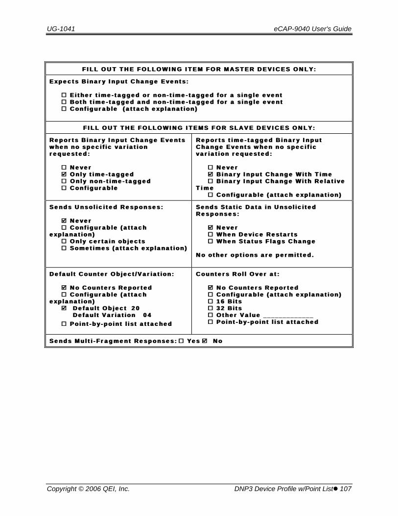
UG-1041 eCAP-9040 User's Guide
Copyright © 2006 QEI, Inc. DNP3 Device Profile w/Point Listl 107
F I L L O U T T H E F O L L O W I N G I T E M F O R M A S T E R D E V I C E S O N L Y :F I L L O U T T H E F O L L O W I N G I T E M F O R M A S T E R D E V I C E S O N L Y :
E x p e c t s B i n a r y I n p u t C h a n g e E v e n t s :E x p e c t s B i n a r y I n p u t C h a n g e E v e n t s :
¨̈ E i t h e r t i m e - t a g g e d o r n o n - t i m e - t a g g e d f o r a s i n g l e e v e n t E i t h e r t i m e - t a g g e d o r n o n - t i m e - t a g g e d f o r a s i n g l e e v e n t¨̈ B o t h t i m e - t a g g e d a n d n o n - t i m e - t a g g e d f o r a s i n g l e e v e n t B o t h t i m e - t a g g e d a n d n o n - t i m e - t a g g e d f o r a s i n g l e e v e n t¨̈ C o n f i g u r a b l e ( a t t a c h e x p l a n a t i o n ) C o n f i g u r a b l e ( a t t a c h e x p l a n a t i o n )
F I L L O U T T H E F O L L O W I N G I T E M S F O R S L A V E D E V I C E S O N L Y :F I L L O U T T H E F O L L O W I N G I T E M S F O R S L A V E D E V I C E S O N L Y :
R e p o r t s B i n a r y I n p u t C h a n g e E v e n t sR e p o r t s B i n a r y I n p u t C h a n g e E v e n t sw h e n n o s p e c i f i c v a r i a t i o nw h e n n o s p e c i f i c v a r i a t i o nr e q u e s t e d :r e q u e s t e d :
¨̈ N e v e r N e v e rþþ O n l y t i m e - t a g g e d O n l y t i m e - t a g g e d¨̈ O n l y n o n - t i m e - t a g g e d O n l y n o n - t i m e - t a g g e d ¨̈ C o n f i g u r a b l e C o n f i g u r a b l e
R e p o r t s t i m e - t a g g e d B i n a r y I n p u tR e p o r t s t i m e - t a g g e d B i n a r y I n p u tC h a n g e E v e n t s w h e n n o s p e c i f i cC h a n g e E v e n t s w h e n n o s p e c i f i cv a r i a t i o n r e q u e s t e d :v a r i a t i o n r e q u e s t e d :
¨̈ N e v e r N e v e rþþ B i n a r y I n p u t C h a n g e W i t h T i m e B i n a r y I n p u t C h a n g e W i t h T i m e¨̈ B i n a r y I n p u t C h a n g e W i t h R e l a t i v e B i n a r y I n p u t C h a n g e W i t h R e l a t i v e
T i m eT i m e¨̈ C o n f i g u r a b l e ( a t t a c h e x p l a n a t i o n ) C o n f i g u r a b l e ( a t t a c h e x p l a n a t i o n )
S e n d s U n s o l i c i t e d R e s p o n s e s :S e n d s U n s o l i c i t e d R e s p o n s e s :
þþ N e v e r N e v e r¨̈ C o n f i g u r a b l e ( a t t a c h C o n f i g u r a b l e ( a t t a c h
e x p l a n a t i o n )e x p l a n a t i o n )¨̈ O n l y c e r t a i n o b j e c t s O n l y c e r t a i n o b j e c t s¨̈ S o m e t i m e s ( a t t a c h e x p l a n a t i o n ) S o m e t i m e s ( a t t a c h e x p l a n a t i o n )
S e n d s S t a t i c D a t a i n U n s o l i c i t e dS e n d s S t a t i c D a t a i n U n s o l i c i t e dR e s p o n s e s :R e s p o n s e s :
þþ N e v e r N e v e r¨̈ W h e n D e v i c e R e s t a r t s W h e n D e v i c e R e s t a r t s¨̈ W h e n S t a t u s F l a g s C h a n g e W h e n S t a t u s F l a g s C h a n g e
N o o t h e r o p t i o n s a r e p e r m i t t e d .N o o t h e r o p t i o n s a r e p e r m i t t e d .
D e f a u l t C o u n t e r O b j e c t / V a r i a t i o n :D e f a u l t C o u n t e r O b j e c t / V a r i a t i o n :
þþ N o C o u n t e r s R e p o r t e d N o C o u n t e r s R e p o r t e d¨̈ C o n f i g u r a b l e ( a t t a c h C o n f i g u r a b l e ( a t t a c h
e x p l a n a t i o n )e x p l a n a t i o n )þþ D e f a u l t O b j e c t D e f a u l t O b j e c t 2 02 0 D e f a u l t V a r i a t i o n D e f a u l t V a r i a t i o n 0 40 4
¨̈ P o i n t - b y - p o i n t l i s t a t t a c h e d P o i n t - b y - p o i n t l i s t a t t a c h e d
C o u n t e r s R o l l O v e r a t :C o u n t e r s R o l l O v e r a t :
þþ N o C o u n t e r s R e p o r t e d N o C o u n t e r s R e p o r t e d¨̈ C o n f i g u r a b l e ( a t t a c h e x p l a n a t i o n ) C o n f i g u r a b l e ( a t t a c h e x p l a n a t i o n )¨̈ 1 6 B i t s 1 6 B i t s¨̈ 3 2 B i t s 3 2 B i t s¨̈ O t h e r V a l u e _ _ _ _ _ _ _ _ _ _ _ _ _ O t h e r V a l u e _ _ _ _ _ _ _ _ _ _ _ _ _¨̈ P o i n t - b y - p o i n t l i s t a t t a c h e d P o i n t - b y - p o i n t l i s t a t t a c h e d
S e n d s M u l t i - F r a g m e n t R e s p o n s e s :S e n d s M u l t i - F r a g m e n t R e s p o n s e s : ¨̈ Y e s Y e s þþ N o N o
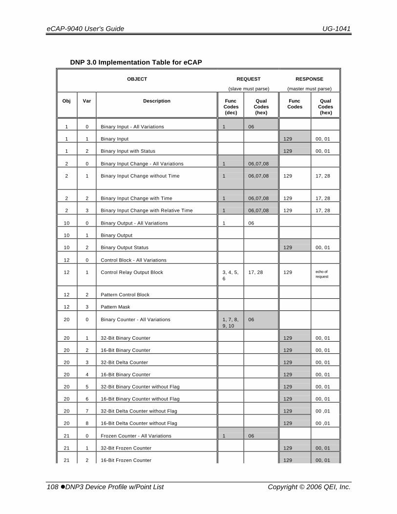
eCAP-9040 User's Guide UG-1041
108 lDNP3 Device Profile w/Point List Copyright © 2006 QEI, Inc.
DNP 3.0 Implementation Table for eCAP
OBJECT REQUEST
(slave must parse)
RESPONSE
(master must parse)
Obj Var Description FuncCodes(dec)
QualCodes(hex)
FuncCodes
QualCodes(hex)
1 0 Binary Input - All Variations 1 06
1 1 Binary Input 129 00, 01
1 2 Binary Input with Status 129 00, 01
2 0 Binary Input Change - All Variations 1 06,07,08
2 1 Binary Input Change without Time 1 06,07,08 129 17, 28
2 2 Binary Input Change with Time 1 06,07,08 129 17, 28
2 3 Binary Input Change with Relative Time 1 06,07,08 129 17, 28
10 0 Binary Output - All Variations 1 06
10 1 Binary Output
10 2 Binary Output Status 129 00, 01
12 0 Control Block - All Variations
12 1 Control Relay Output Block 3, 4, 5,6
17, 28 129 echo ofrequest
12 2 Pattern Control Block
12 3 Pattern Mask
20 0 Binary Counter - All Variations 1, 7, 8,9, 10
06
20 1 32-Bit Binary Counter 129 00, 01
20 2 16-Bit Binary Counter 129 00, 01
20 3 32-Bit Delta Counter 129 00, 01
20 4 16-Bit Binary Counter 129 00, 01
20 5 32-Bit Binary Counter without Flag 129 00, 01
20 6 16-Bit Binary Counter without Flag 129 00, 01
20 7 32-Bit Delta Counter without Flag 129 00 ,01
20 8 16-Bit Delta Counter without Flag 129 00 ,01
21 0 Frozen Counter - All Variations 1 06
21 1 32-Bit Frozen Counter 129 00, 01
21 2 16-Bit Frozen Counter 129 00, 01

UG-1041 eCAP-9040 User's Guide
Copyright © 2006 QEI, Inc. DNP3 Device Profile w/Point Listl 109
OBJECT REQUEST
(slave must parse)
RESPONSE
(master must parse)
Obj Var Description FuncCodes(dec)
QualCodes(hex)
FuncCodes
QualCodes(hex)
21 3 32-Bit Frozen Delta Counter
21 4 16-Bit Frozen Delta Counter
21 5 32-Bit Frozen Counter with Time of Freeze
21 6 16-Bit Frozen Counter with Time of Freeze
21 7 32-Bit Frozen Delta Counter with Time ofFreeze
21 8 16-Bit Frozen Delta Counter with Time ofFreeze
21 9 32-Bit Frozen Counter without Flag 129 00, 01
21 10 16-Bit Frozen Counter without Flag 129 00, 01
21 11 32-Bit Frozen Delta Counter without Flag
21 12 16-Bit Frozen Delta Counter without Flag
22 0 Counter Change Event - All Variations 1 06,07,08
22 1 32-Bit Counter Change Event without Time 129 17, 28
22 2 16-Bit Counter Change Event without Time 129 17, 28
22 3 32-Bit Delta Counter Change Event withoutTime
22 4 16-Bit Delta Counter Change Event withoutTime
22 5 32-Bit Counter Change Event with Time
22 6 16-Bit Counter Change Event with Time
22 7 32-Bit Delta Counter Change Event with Time
22 8 16-Bit Delta Counter Change Event with Time
23 0 Frozen Counter Event - All Variations
23 1 32-Bit Frozen Counter Event without Time
23 2 16-Bit Frozen Counter Event without Time
23 3 32-Bit Frozen Delta Counter Event without Time
23 4 16-Bit Frozen Delta Counter Event without Time
23 5 32-Bit Frozen Counter Event with Time
23 6 16-Bit Frozen Counter Event with Time
23 7 32-Bit Frozen Delta Counter Event with Time
23 8 16-Bit Frozen Delta Counter Event with Time
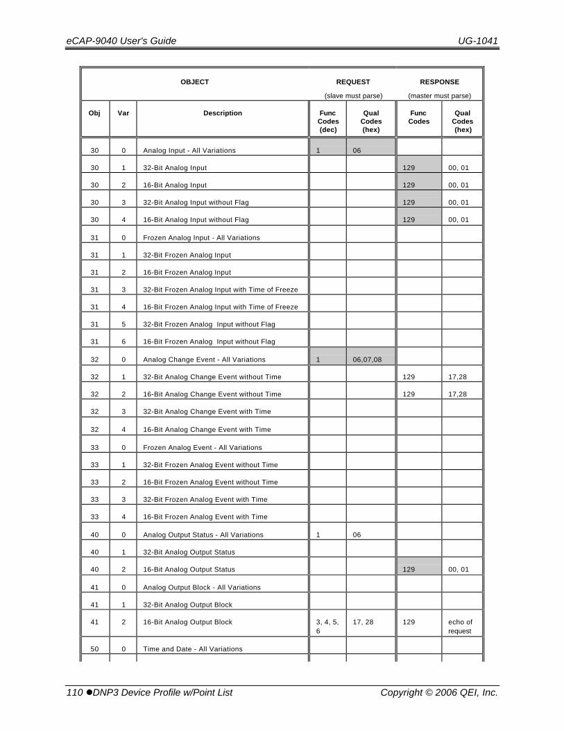
eCAP-9040 User's Guide UG-1041
110 lDNP3 Device Profile w/Point List Copyright © 2006 QEI, Inc.
OBJECT REQUEST
(slave must parse)
RESPONSE
(master must parse)
Obj Var Description FuncCodes(dec)
QualCodes(hex)
FuncCodes
QualCodes(hex)
30 0 Analog Input - All Variations 1 06
30 1 32-Bit Analog Input 129 00, 01
30 2 16-Bit Analog Input 129 00, 01
30 3 32-Bit Analog Input without Flag 129 00, 01
30 4 16-Bit Analog Input without Flag 129 00, 01
31 0 Frozen Analog Input - All Variations
31 1 32-Bit Frozen Analog Input
31 2 16-Bit Frozen Analog Input
31 3 32-Bit Frozen Analog Input with Time of Freeze
31 4 16-Bit Frozen Analog Input with Time of Freeze
31 5 32-Bit Frozen Analog Input without Flag
31 6 16-Bit Frozen Analog Input without Flag
32 0 Analog Change Event - All Variations 1 06,07,08
32 1 32-Bit Analog Change Event without Time 129 17,28
32 2 16-Bit Analog Change Event without Time 129 17,28
32 3 32-Bit Analog Change Event with Time
32 4 16-Bit Analog Change Event with Time
33 0 Frozen Analog Event - All Variations
33 1 32-Bit Frozen Analog Event without Time
33 2 16-Bit Frozen Analog Event without Time
33 3 32-Bit Frozen Analog Event with Time
33 4 16-Bit Frozen Analog Event with Time
40 0 Analog Output Status - All Variations 1 06
40 1 32-Bit Analog Output Status
40 2 16-Bit Analog Output Status 129 00, 01
41 0 Analog Output Block - All Variations
41 1 32-Bit Analog Output Block
41 2 16-Bit Analog Output Block 3, 4, 5,6
17, 28 129 echo ofrequest
50 0 Time and Date - All Variations
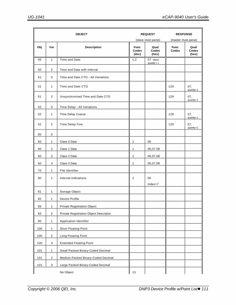
UG-1041 eCAP-9040 User's Guide
Copyright © 2006 QEI, Inc. DNP3 Device Profile w/Point Listl 111
OBJECT REQUEST
(slave must parse)
RESPONSE
(master must parse)
Obj Var Description FuncCodes(dec)
QualCodes(hex)
FuncCodes
QualCodes(hex)
50 1 Time and Date 1,2 07 wherequantity = 1
50 2 Time and Date with Interval
51 0 Time and Date CTO - All Variations
51 1 Time and Date CTO 129 07,quantity=1
51 2 Unsynchronized Time and Date CTO 129 07,quantity=1
52 0 Time Delay - All Variations
52 1 Time Delay Coarse 129 07,quantity=1
52 2 Time Delay Fine 129 07,quantity=1
60 0
60 1 Class 0 Data 1 06
60 2 Class 1 Data 1 06,07,08
60 3 Class 2 Data 1 06,07,08
60 4 Class 3 Data 1 06,07,08
70 1 File Identifier
80 1 Internal Indications 2 00
index=7
81 1 Storage Object
82 1 Device Profile
83 1 Private Registration Object
83 2 Private Registration Object Descriptor
90 1 Application Identifier
100 1 Short Floating Point
100 2 Long Floating Point
100 3 Extended Floating Point
101 1 Small Packed Binary-Coded Decimal
101 2 Medium Packed Binary-Coded Decimal
101 3 Large Packed Binary-Coded Decimal
No Object 13

eCAP-9040 User's Guide UG-1041
112 lDNP3 Device Profile w/Point List Copyright © 2006 QEI, Inc.
OBJECT REQUEST
(slave must parse)
RESPONSE
(master must parse)
Obj Var Description FuncCodes(dec)
QualCodes(hex)
FuncCodes
QualCodes(hex)
No Object 23 (see4.14)

UG-1041 eCAP-9040 User's Guide
Copyright © 2006 QEI, Inc. DNP3 Device Profile w/Point Listl 113
Basic Input Data Registers – Analog Points
Object /Variation
/ Class ParameterPoint
Address Units Range30/4/0 OR32/2/2 Secondary Voltage (1 phase) 0 0.1 Volts
30/4/0 OR32/2/2 Voltage w/ Correction (1 phase) 1 0.1 Volts
30/4/0 OR32/2/2 Current (1 phase) 2 Amps
30/4/0 OR32/2/2 KW (1 phase x3) 3 KW
30/4/0 OR32/2/2 kVAr (1 phase x3) 4 kVAr
30/4/0 OR32/2/2 kVA (1 phase x3) 5 kVA
30/4/0 OR32/2/2 Power Factor 6 0.1 %
30/4/0 OR32/2/2 Phase Angle 7 Degrees
30/4/0 OR32/2/2 Neutral Current 8 Amps
30/4/0 OR32/2/2 Ambient Temperature 9 Degrees F
30/4/0 OR32/2/2 Indoor Temperature 10 Degrees F
30/4/0 OR32/2/3 Reserved 11
30/4/0 OR32/2/3 Reserved 12
30/4/0 OR32/2/3 Reserved 13
30/4/0 OR32/2/3 Reserved 14
30/4/0 OR32/2/2 Number of Switch Operations 15 Trips
30/4 Op-Delay pending timer 16 Seconds
30/4 Anti-Oscillate Pending Timer 17 Seconds
30/4 Discharge Pending Timer 18 Seconds
30/4 MiniCap Firmware Version 19
30/4 ProtoCom Firmware Version 20

eCAP-9040 User's Guide UG-1041
114 lDNP3 Device Profile w/Point List Copyright © 2006 QEI, Inc.
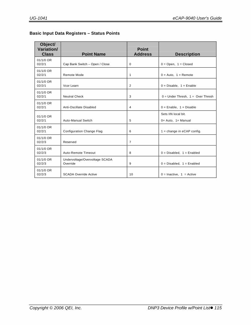
UG-1041 eCAP-9040 User's Guide
Copyright © 2006 QEI, Inc. DNP3 Device Profile w/Point Listl 115
Basic Input Data Registers – Status Points
Object/Variation/
Class Point NamePoint
Address Description01/1/0 OR02/2/1 Cap Bank Switch – Open / Close 0 0 = Open, 1 = Closed
01/1/0 OR02/2/1 Remote Mode 1 0 = Auto, 1 = Remote
01/1/0 OR02/2/1 Vcor Learn 2 0 = Disable, 1 = Enable
01/1/0 OR02/2/1 Neutral Check 3 0 = Under Thresh, 1 = Over Thresh
01/1/0 OR02/2/1 Anti-Oscillate Disabled 4 0 = Enable, 1 = Disable
01/1/0 OR02/2/1 Auto-Manual Switch 5
Sets IIN local bit.
0= Auto, 1= Manual
01/1/0 OR02/2/1 Configuration Change Flag 6 1 = change in eCAP config.
01/1/0 OR02/2/3 Reserved 7
01/1/0 OR02/2/3 Auto-Remote Timeout 8 0 = Disabled, 1 = Enabled
01/1/0 OR02/2/3
Undervoltage/Overvoltage SCADAOverride 9 0 = Disabled, 1 = Enabled
01/1/0 OR02/2/3 SCADA Override Active 10 0 = Inactive, 1 = Active

eCAP-9040 User's Guide UG-1041
116 lDNP3 Device Profile w/Point List Copyright © 2006 QEI, Inc.
Basic Output Data Registers – Control Points
Object /Variation Point Name
PointAddress
OperationType Description
OperationConditions
12/1 Cap Bank Switch Trip/Close 0 Latched Off = Trip
On = Close
Auto-Manual(Status Input 5)must be 0 (Auto)and Cap BankSwitchClosed/Open(Status Input 1)must be On.
12/1 Remote Mode / Auto Mode 1 Latched Off = Auto
On = Remote
Auto-Manual(Status Input 5)must be Off.
12/1 Vcor Learn 2 Latched Off = Disabled
On = Enabled
Auto-Manual(Status Input 5)must be Off.
12/1 Discharge Delay – 10/5minutes
3 Latched Off = 5 minutes
On = 10 minutes
Auto-Manual(Status Input 5)must be Off.
12/1 Anti-OscillateDisabled/Enabled
4 Latched Off = Enabled
On = Disabled
Auto-Manual(Status Input 5)must be Off.
12/1 Auto-Remote Timeout Enable 5 Latched Off = Disabled
On = Enabled
Auto-Manual(Status Input 5)must be Off.
12/1 Undervoltage/OvervoltageSCADA Override
6 Latched Off = Disabled
On - Enabled
Auto-Manual(Status Input 5)must be Off.

UG-1041 eCAP-9040 User's Guide
Copyright © 2006 QEI, Inc. DNP3 Device Profile w/Point Listl 117
Operating Parameter Registers – Analog Input Deadbands
Object /Variation Parameter
PointAddress Units Default Range
41 / 2Secondary Voltage (1 phase) 0 0.1 Volts 5.0
41 / 2 Voltage w/ Correction (1 phase) 1 0.1 Volts 5.0
41 / 2 Current (1 phase) 2 Amps 50
41 / 2 KW (1 phase x3) 3 KW 500
41 / 2 KVAr (1 phase x3) 4 kVAr 500
41 / 2 kVA (1 phase x3) 5 kVA 500
41 / 2 Power Factor 6 0.1 % 10.0%
41 / 2 Phase Angle 7 Degrees 20
41 / 2 Neutral Current 8 Amps 4
41 / 2 Ambient Temperature 9 Degrees F 20
41 / 2 Indoor Temperature 10 Degrees F 20
41 / 2 Reserved 11 32767
41 / 2 Reserved 12 32767
41 / 2 Reserved 13 32767
41 / 2 Reserved 14 32767
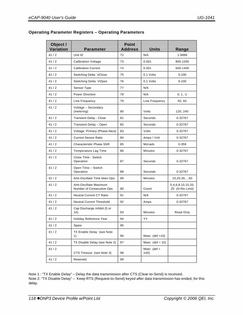
eCAP-9040 User's Guide UG-1041
118 lDNP3 Device Profile w/Point List Copyright © 2006 QEI, Inc.
Operating Parameter Registers – Operating Parameters
Object /Variation Parameter
PointAddress Units Range
41 / 2 Unit ID 72 N/A 1-9999
41 / 2 Calibration Voltage 73 0.001 800-1200
41 / 2 Calibration Current 74 0.001 600-1400
41 / 2 Switching Delta VClose 75 0.1 Volts 0-100
41 / 2 Switching Delta VOpen 76 0.1 Volts 0-100
41 / 2 Sensor Type 77 N/A
41 / 2 Power Direction 78 N/A 0, 1, -1
41 / 2 Line Frequency 79 Line Frequency 50, 60
41 / 2 Voltage – Secondary(metering) 80 Volts 120, 240
41 / 2 Transient Delay - Close 81 Seconds 0-32767
41 / 2 Transient Delay – Open 82 Seconds 0-32767
41 / 2 Voltage: Primary (Phase-Neut) 83 Volts 0-32767
41 / 2 Current Sensor Ratio 84 Amps / Volt 0-32767
41 / 2 Characteristic Phase Shift 85 Micrads 0-359
41 / 2 Temperature Lag Time 86 Minutes 0-32767
41 / 2 Close Time - SwitchOperation 87 Seconds 0-32767
41 / 2 Open Time – SwitchOperation 88 Seconds 0-32767
41 / 2 Anti-Oscillate Time btwn Ops 89 Minutes 10,20,30,…60
41 / 2 Anti-Oscillate MaximumNumber of Consecutive Ops 90 Count
0,4,6,8,10,15,20,25 (0=No Limit)
41 / 2 Neutral Current CT Ratio 91 N/A 0-32767
41 / 2 Neutral Current Threshold 92 Amps 0-32767
41 / 2 Cap Discharge Inhibit (5 or10) 93 Minutes Read Only
41 / 2 Holiday Reference Year 94 YY
41 / 2 Spare 95
41 / 2 TX Enable Delay (see Note1) 96 Msec (def =10)
41 / 2 TX Disable Delay (see Note 2) 97 Msec (def = 10)
41 / 2CTS Timeout (see Note 3) 98
Msec (def =100)
41 / 2 Reserved 99
Note 1 : “TX Enable Delay” – Delay the data transmission after CTS (Clear-to-Send) is received.Note 2: “TX Disable Delay” – Keep RTS (Request-to-Send) keyed after data transmission has ended, for thisdelay.

UG-1041 eCAP-9040 User's Guide
Copyright © 2006 QEI, Inc. DNP3 Device Profile w/Point Listl 119
Note 3: “CTS Timeout”: -- If CTS is false, wait for this time, then send the data anyway.

eCAP-9040 User's Guide UG-1041
120 lCAP-9040 Communications Upgrade Kit Copyright © 2006 QEI, Inc.
9. CAP-9040 Communications Upgrade KitA “Communications Upgradeable” version of the eCAP-9040 is available for customerswho do not have an immediate need for SCADA communications capability. Theupgradeable unit lacks a SCADA communications board, RS-232 Radio InterfaceBoard, and a radio power supply. The communications board and power supply maybe added at a later time by purchasing QEI’s “eCAP-9040 Communication Upgrade Kit”(QEI Part No. 40-057778-001). The kit contains a power supply (for a radio), SCADACommunications board, Radio Interface Board, and all necessary cabling, hardware,etc. to upgrade the unit to “Communications Ready”. (Radio is not included)
Please read through all of the following instructions carefully before attempting toupgrade the eCAP-9040.
9.1 Preparation
Inspect the Kit against the following list to determine that all parts have been included:
QEI Part No. Description Qty Item No
10-057309-001 Battery 3V Coin Cell BR1225 1 (4)
10-057510-001 Pwr Supply 95-264VAC IN/+12VDC OUT 1 (3)
20-055646-001 Cable Ties 10 (9)
20-056236-001 Cable Clips 10 (10)
20-056717-001 Hdwr Nut KEPS 4-40 Hex 4 (1)
20-056717-002 Hdwr Nut KEPS 6-32 Hex 4 (8)
20-056808-001 Hdwr Spacer Rnd .187 O.D. x .250L 4 (2)
40-057728-001 SCADA Communications Board 1 (5)
40-057807-001 RS-232 Radio Interface Board 1 (11)
30-059239-001 Radio Interface Board Mtg Brkt.* 1 (12)
20-055600-030 Lockwasher, #6, S/S * 3 (13)
20-055656-012 Standoff M-M 6-32 x ½” * 1 (14)
20-056859-116 Hdwr, Screw 6-32 x ¼” Rnd Hd Phil S/S * 3 (15)
10-057547-001 Fiber Cable 4” Long * 2 (16)
40-057808-001 eCAP DB9M Radio Intface Cable ** 1 (6)
40-057808-002 eCAP DB25M Radio Intface Cable ** 1 (7)

UG-1041 eCAP-9040 User's Guide
Copyright © 2006 QEI, Inc. CAP-9040 Communications Upgrade Kitl 121
* Parts required to attach Radio Interface Board to SCADA Communications Bd.
** Used to connect RS-232 Radio Interface Board to Radio.
9.2 Power Supply Installation
Refer to Figure 1 (next page) to perform the following steps:
1) Make sure all power is disconnected.
2) Open the eCAP front panel by turning the knurled screws on the right sideof the faceplate counter-clockwise approximately one full turn.
3) Once the faceplate is open, note that there are four threaded mountingstuds located on the right chassis wall inside the unit.
4) Place four round spacers, (item 2), over the threaded mounting studs.
5) Take the Radio Power supply (item 3) and orient it in the eCAP as shown infigure 1, with the 6-pin white Molex-style connector facing up, and the 2-pinwhite Molex connector facing down.
6) Place the Radio Power Supply on the threaded mounting studs/spacers,and secure using the four 4-40 hex nuts (item 1).
7) Connect DC Output Plug P2 (Red/Black wiring) onto the 6-pin connector,and AC Input Plug P1 (Black/White wiring) onto the 2-pin connector on thepower supply.
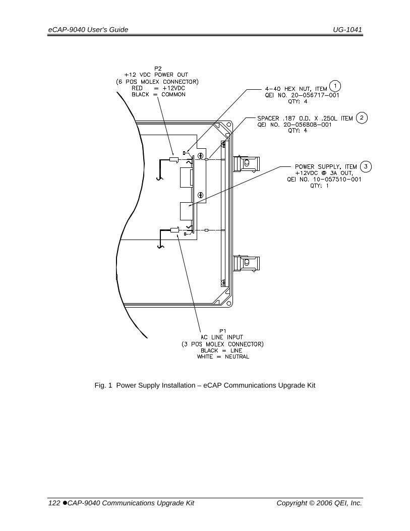
eCAP-9040 User's Guide UG-1041
122 lCAP-9040 Communications Upgrade Kit Copyright © 2006 QEI, Inc.
Fig. 1 Power Supply Installation – eCAP Communications Upgrade Kit
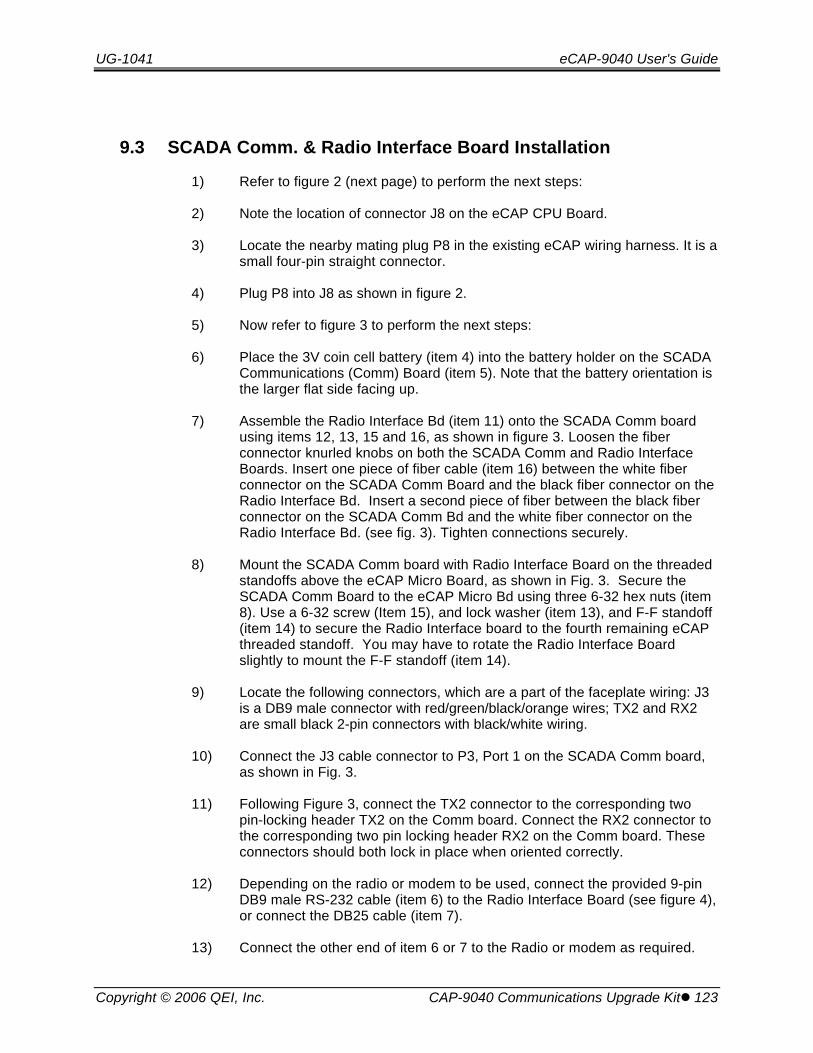
UG-1041 eCAP-9040 User's Guide
Copyright © 2006 QEI, Inc. CAP-9040 Communications Upgrade Kitl 123
9.3 SCADA Comm. & Radio Interface Board Installation
1) Refer to figure 2 (next page) to perform the next steps:
2) Note the location of connector J8 on the eCAP CPU Board.
3) Locate the nearby mating plug P8 in the existing eCAP wiring harness. It is asmall four-pin straight connector.
4) Plug P8 into J8 as shown in figure 2.
5) Now refer to figure 3 to perform the next steps:
6) Place the 3V coin cell battery (item 4) into the battery holder on the SCADACommunications (Comm) Board (item 5). Note that the battery orientation isthe larger flat side facing up.
7) Assemble the Radio Interface Bd (item 11) onto the SCADA Comm boardusing items 12, 13, 15 and 16, as shown in figure 3. Loosen the fiberconnector knurled knobs on both the SCADA Comm and Radio InterfaceBoards. Insert one piece of fiber cable (item 16) between the white fiberconnector on the SCADA Comm Board and the black fiber connector on theRadio Interface Bd. Insert a second piece of fiber between the black fiberconnector on the SCADA Comm Bd and the white fiber connector on theRadio Interface Bd. (see fig. 3). Tighten connections securely.
8) Mount the SCADA Comm board with Radio Interface Board on the threadedstandoffs above the eCAP Micro Board, as shown in Fig. 3. Secure theSCADA Comm Board to the eCAP Micro Bd using three 6-32 hex nuts (item8). Use a 6-32 screw (Item 15), and lock washer (item 13), and F-F standoff(item 14) to secure the Radio Interface board to the fourth remaining eCAPthreaded standoff. You may have to rotate the Radio Interface Boardslightly to mount the F-F standoff (item 14).
9) Locate the following connectors, which are a part of the faceplate wiring: J3is a DB9 male connector with red/green/black/orange wires; TX2 and RX2are small black 2-pin connectors with black/white wiring.
10) Connect the J3 cable connector to P3, Port 1 on the SCADA Comm board,as shown in Fig. 3.
11) Following Figure 3, connect the TX2 connector to the corresponding twopin-locking header TX2 on the Comm board. Connect the RX2 connector tothe corresponding two pin locking header RX2 on the Comm board. Theseconnectors should both lock in place when oriented correctly.
12) Depending on the radio or modem to be used, connect the provided 9-pinDB9 male RS-232 cable (item 6) to the Radio Interface Board (see figure 4),or connect the DB25 cable (item 7).
13) Connect the other end of item 6 or 7 to the Radio or modem as required.
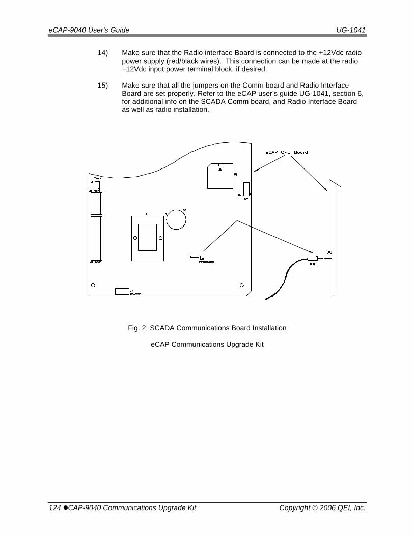
eCAP-9040 User's Guide UG-1041
124 lCAP-9040 Communications Upgrade Kit Copyright © 2006 QEI, Inc.
14) Make sure that the Radio interface Board is connected to the +12Vdc radiopower supply (red/black wires). This connection can be made at the radio+12Vdc input power terminal block, if desired.
15) Make sure that all the jumpers on the Comm board and Radio InterfaceBoard are set properly. Refer to the eCAP user’s guide UG-1041, section 6,for additional info on the SCADA Comm board, and Radio Interface Boardas well as radio installation.
Fig. 2 SCADA Communications Board Installation
eCAP Communications Upgrade Kit
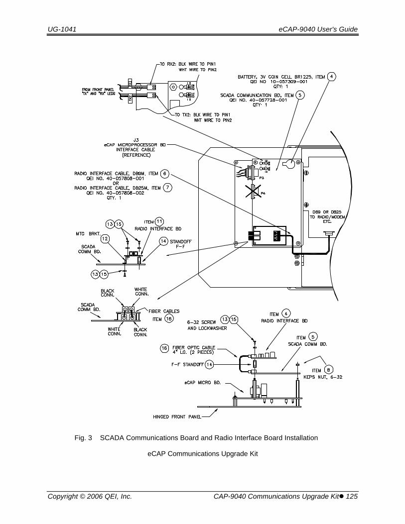
UG-1041 eCAP-9040 User's Guide
Copyright © 2006 QEI, Inc. CAP-9040 Communications Upgrade Kitl 125
Fig. 3 SCADA Communications Board and Radio Interface Board Installation
eCAP Communications Upgrade Kit

eCAP-9040 User's Guide UG-1041
126 lCAP-9040 Communications Upgrade Kit Copyright © 2006 QEI, Inc.
Fig. 4 SCADA Communications Board and Radio Interface Board Installation
eCAP Communications Upgrade Kit