ntpc anta training report
DESCRIPTION
full description of thermal power plantTRANSCRIPT
Chapter-1
INTRODUCTION
National Thermal Power Corporation Ltd (NTPC) was incorporated in 1975 by an Act of
parliament, to supplement the efforts of the states for quicker and greater capacity addition
in thermal power generation .In1997 the Department of Public enterprises, Government of
india status with power of operational autonomy to the board of NTPC . This helped NTPC
in speedy implementation of power projects. Recently NTPC has been awarded the
Maharatna status which has given it greater autonomy.
In line with its vision and mission over the last five years NTPC has grown
to become the largest power utility in India with a commission degeneration capacity of
34,754MW (asonJuly,2011) .Besides largest power generation utility NTPC has also grown
to become the number one independent power in Asia and second globally in 2009 (by Platt
a division of McGraw-Hill companies) ,5largest company in Asia and 317Largest company
in the world (FORBESranking–2009) .NTPC has also thehonor of becoming the 6th
largest
the power generator in the world and second most efficient in terms of capacity utilization
among stop 10 utilities in the world.
In line with the changing business environment ,NTPC has expanded its
operation in the area of Hydro Power and cover substantial ground in the area sof Coal and
Mining .Oil& Gas Value chain ,Power Trading and Distribution .With the forward and
backward plans ,NTPC has been re-christened as “NTPC Limited“ since 7th
Nov2005.
1
Chapter-2
NTPC MISSION AND VISION
NTPC ultimately produce and deliver quality power in optimum cost and eco-friendly
manner through concerted team effort sand effective system. Being an PSU,An has
derivedits mission an dvision aliging with that of the Corporate Mission and Vision.
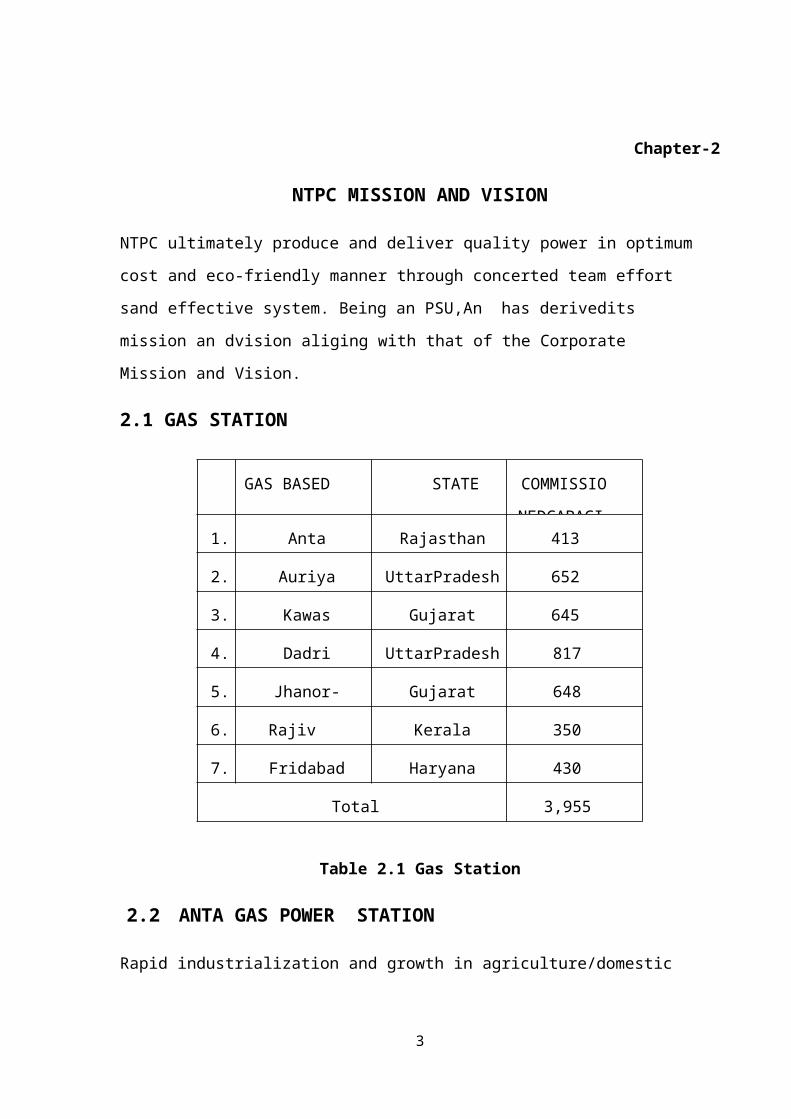
2.1 GAS STATION
Table 2.1 Gas
Station
2.2 ANTA GAS POWER STATION
Rapid industrialization and growth in agriculture/domestic consumption of power in the North
India was putting lot of strain on the power grid .To overcome the gap between supply and
demand NTPC setup its first Gas Power Station at Anta .Presently NTPC ,Anta is one of the
seven Gas station of NTPC. Anta project was setup to mitigate the power short again the
Northen region which was estimated between 13-16% of the peak demand during the7th
plan
period.
2
GAS BASED STATE COMMISSI
ONEDCAPA
1. Anta Rajasthan 413
2. Auriya UttarPradesh 652
3. Kawas Gujarat 645
4. Dadri UttarPradesh 817
5. Jhanor- Gandhar Gujarat 648
6. Rajiv
GandhiOCPPk
Kerala 350
7. Fridabad Haryana 430
Total 3,955
2.3 SAILENT FEATURES OF NTPC ANTA
1. Station : Combined Cycle Gas Based Power Station
2. Gas Turbine : 3x 88.71MW
3. Steam Turbine : 1x 153.2MW
4. Total Capacity : 419.33 MW
5. Gas turbine : 88MW,Type ABB Gas turbine,5 Stage
6. GT Comprossor : 18 stage Axial flow (typeVA14018)
7. Combustion Chamber : Single Silotype
3
Chapter-3
POWER GENRATION PROCESS
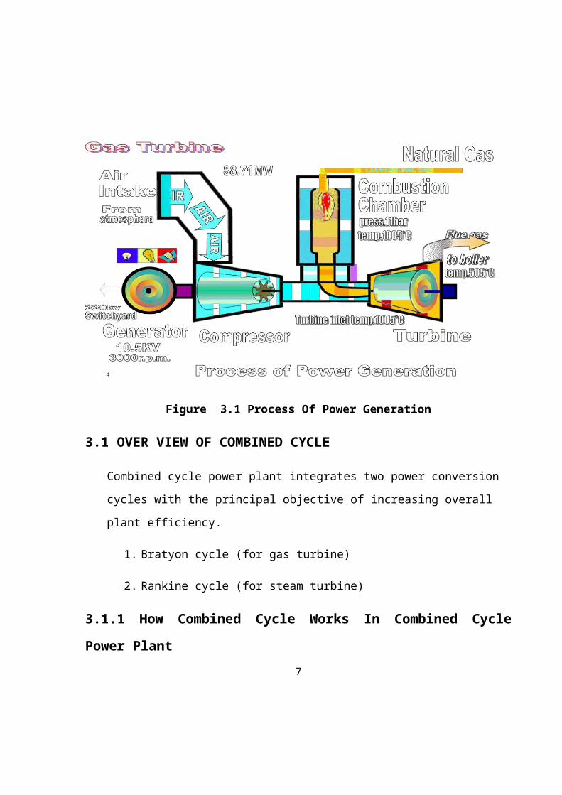
The Gas/Naphtha from pipeline is taken and supplied to GT Combustion chamber where it is
burn as fuel along with air drawn from atmosphere. This heat is then convert into mechanical
energy in the Gas Turbine. Gas turbine through a common shaft rotates Generator, which
produces electric power. Flue gas from the turbine exhaust is used to convert water into steam
in the Waste Heat Recovery Boiler (WHRB).Water required for steam generation is circulated
through the tube sin the boiler, where heat exchange takes place and water gets converted in
to steam. The steam generated from WHRB is used to run a steam turbo generator and
produce electric power. This power is supplied to customer through 220KV lines.
Figure 3.1 Process Of Power Generation
4
3.1 OVER VIEW OF COMBINED CYCLE
Combined cycle power plant integrates two power conversion cycles with the principal
objective of increasing overall plant efficiency.
1. Bratyon cycle (for gas turbine)
2. Rankine cycle (for steam turbine)
3.1.1 How Combined Cycle Works In Combined Cycle Power Plant
Gas turbine exhaust is at temperature of500-550Celcius
Steam generation process for Rankine cycle requires a temperature of500-550Celcius
to generate steam.
Gas turbine exhaust heat can be recovered using a waste heat recovery boiler to
generate steam in a water tube boiler so as a steam turbine on Rankine cycle.
Efficiency of simple gas turbine cycle is 34%.
The efficiency of Rankine cycle is 35%.
The overall efficiency of power generation by combined cycle comes to 49%.
3.2 STEAM TURBINE
Steam Turbine is a heat engine, working On Rankine cycle .The
process includes
1. Heating: Phase change of working medium (from water to steam) and super heating at
constant pressure in Boiler.
2.Expansion: Expansion of the steam in a turbine
3. Pressurization: Pressurization of working medium(water)by boiler feed water pump.
5
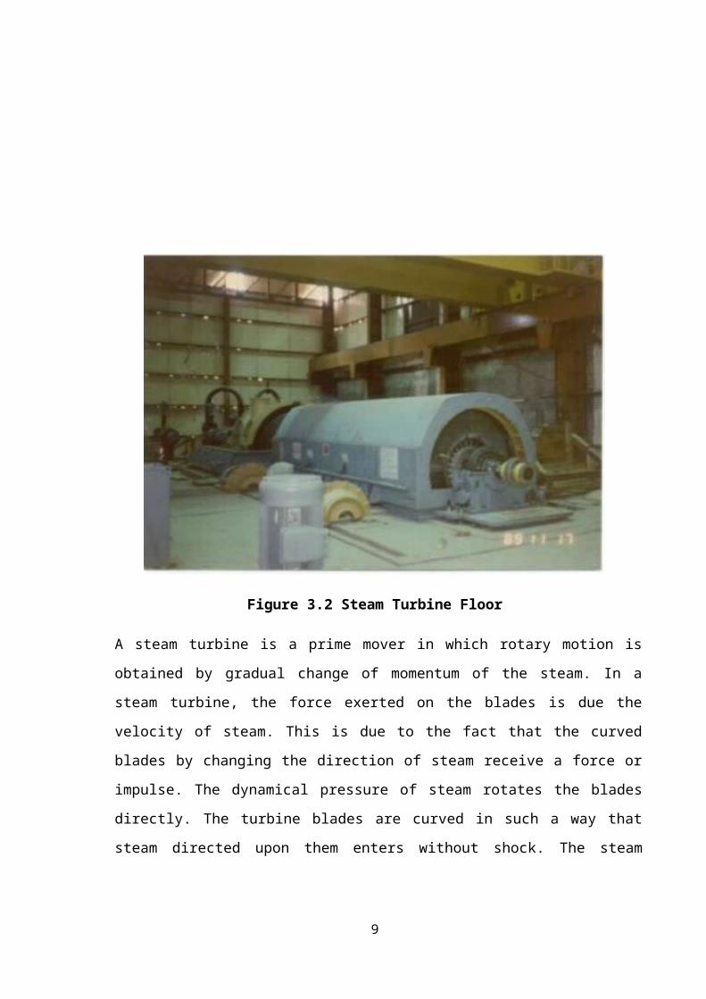
Figure 3.2 Steam Turbine Floor
A steam turbine is a prime mover in which rotary motion is obtained by gradual change of
momentum of the steam. In a steam turbine, the force exerted on the blades is due the
velocity of steam. This is due to the fact that the curved blades by changing the direction of
steam receive a force or impulse. The dynamical pressure of steam rotates the blades
directly. The turbine blades are curved in such a way that steam directed upon them enters
without shock. The steam turbine essentially consists of following two parts. The nozzle in
which the heat energy of high pressure steam is converted into K.E.so that the steam issues
from the nozzle with a very high velocity .The blade which changes the direction of steam.
6
Chapter-4
GAS TURBINE
Gas turbine is a heat engine working on the air standard Brayton cycle.
The process Includes
1. Compression: Compression of working medium (air) taken from atmosphere in a
compressor.
2. Combustion: Increase of working medium temperature by constant ignition of fuel
in combustion chamber.
3. Expansion: Expansion of the product of combustion in a turbine.
4. Rejection: Rejection of heat in the atmosphere.
4.1 OVER VIEW OF GAS TURBINE
1. Air intake system
2. Compressor
3. Combustion Chamber
4. Turbine
5. Generator
6. Gas Fuel System
7. Naphtha Fuel system
7
8
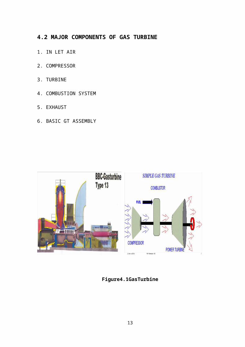
4.2 MAJOR COMPONENTS OF GAS TURBINE
1. IN LET AIR
2. COMPRESSOR
3. TURBINE
4. COMBUSTION SYSTEM
5. EXHAUST
6. BASIC GT ASSEMBLY
Figure4.1GasTurbine
9
Chapter-5
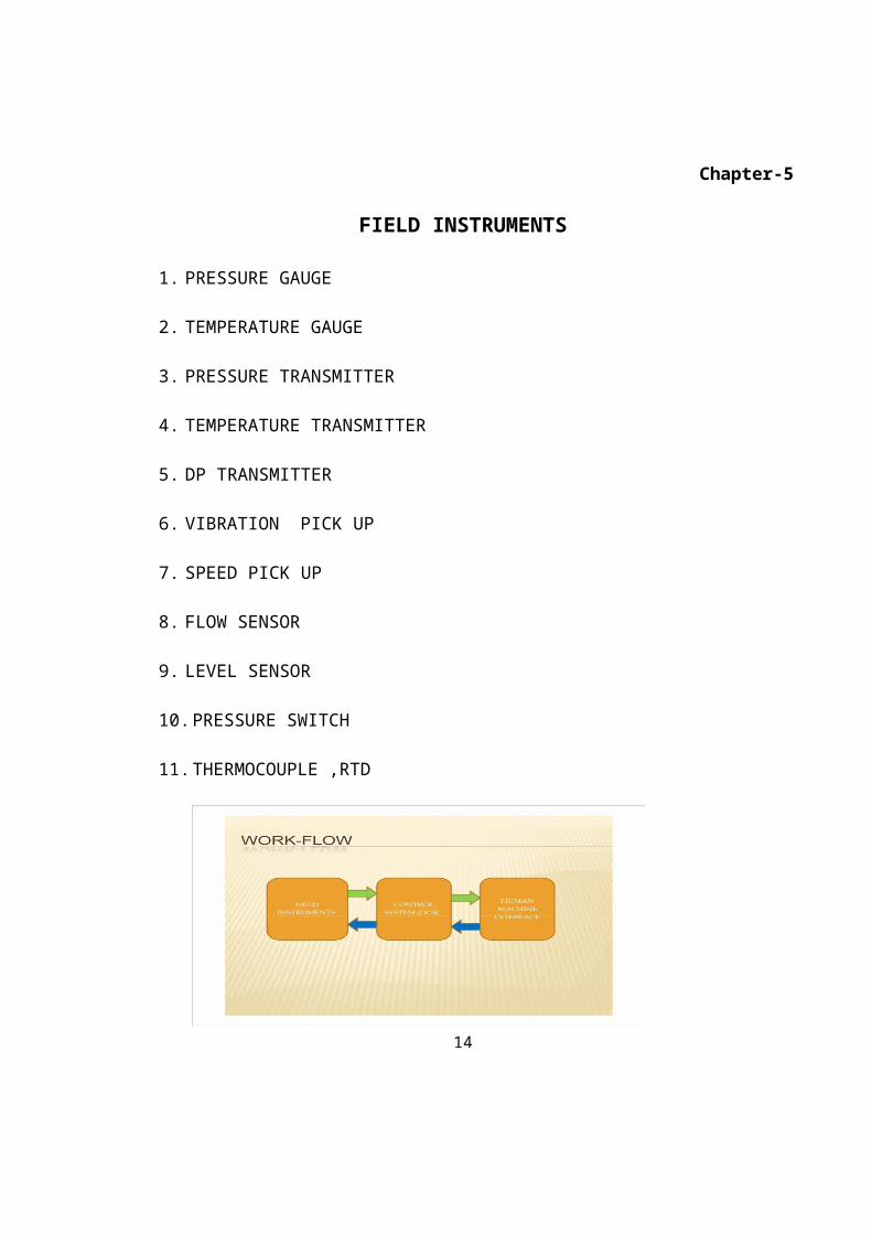
FIELD INSTRUMENTS
1. PRESSURE GAUGE
2. TEMPERATURE GAUGE
3. PRESSURE TRANSMITTER
4. TEMPERATURE TRANSMITTER
5. DP TRANSMITTER
6. VIBRATION PICK UP
7. SPEED PICK UP
8. FLOW SENSOR
9. LEVEL SENSOR
10. PRESSURE SWITCH
11. THERMOCOUPLE ,RTD
Figure 5.1 Work Flow Diagram
10
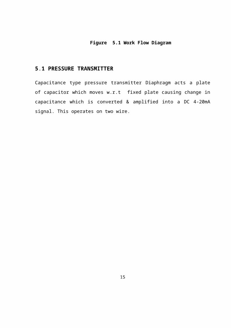
5.1 PRESSURE TRANSMITTER
Capacitance type pressure transmitter Diaphragm acts a plate of capacitor which moves w.r.t
fixed plate causing change in capacitance which is converted & amplified into a DC 4-20mA
signal. This operates on two wire.
Figure 5.2 Pressure Transmitter
11

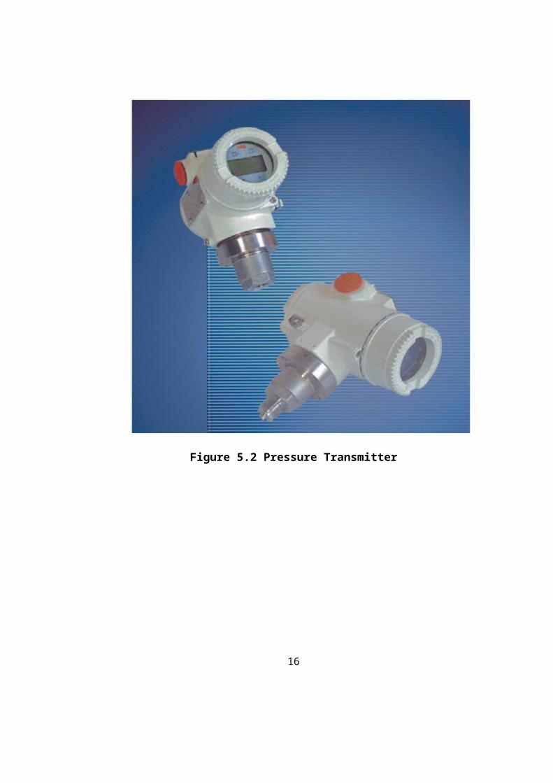
5.2 TEMPERATURE GAUGE
Temperature Gauge is used to measure the temperature of device.
Figure 5.3. Temperature Gauge
12
5.3 FLOW MEASUREMENT
5.3.1 Differential Pressure Flow meters
The basic operating principle :
The pressure drop across the meter is proportional to the square of the flow rate.
The flow rate is obtained by measuring the pressure differential and extracting the
square root
Different pressure flowmeter are:-
1. ORIFICE
2. VENTURI
3. NOZZLE
4. PITOT TUBE
5.3.2 Electromagnetic Flow Meter
When a liquid conductor moves in a pipe having a diameter (D) and travels with an average
velocity (V) through a magnetic field of B intensity, it will induce a voltage (E) according to
the relationship:
E = C B D V
5.4 LEVEL MEASUREMENT
1.Differential Pressure transmitter
Level is measured through Electronic DP transmitter
2. Ultrasonic level transmitter
Level is measured by ultrasonic transmitter mounted on the top of the tank
3. Guided wave radar type level transmitter
13
Generally used for low pressure app
4. Hydra step
Most commonly used for Boiler drum measurement.
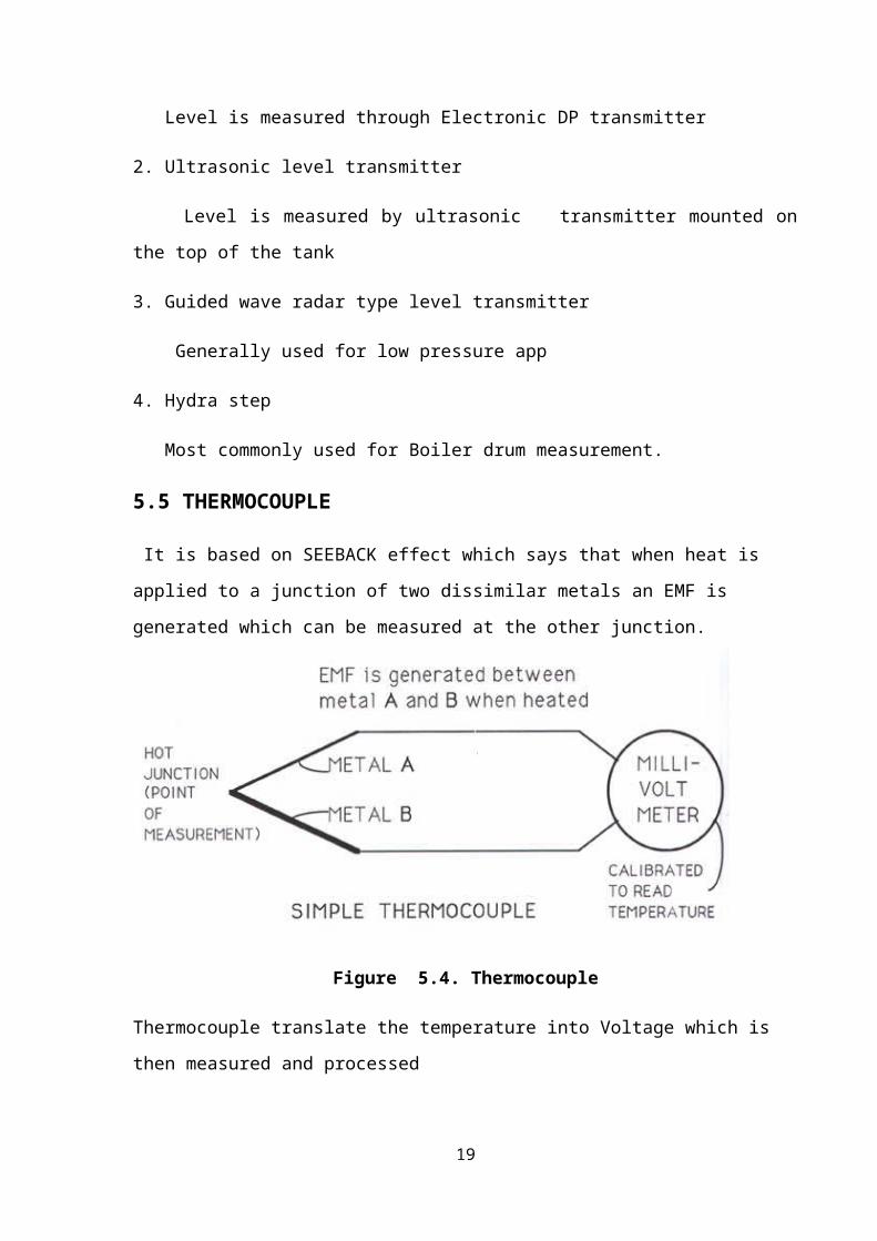
5.5 THERMOCOUPLE
It is based on SEEBACK effect which says that when heat is applied to a junction of two
dissimilar metals an EMF is generated which can be measured at the other junction.
Figure 5.4. Thermocouple
Thermocouple translate the temperature into Voltage which is then measured and processed
to compute numerical Value of temperaturewhen two wires of electrical properties are joined
together at the both end one junction made hot& other junction made cold small electrical current
produced proportional to the difference in the temperature.
14
Chapter-6
GENERATOR
The transformation of mechanical energy into electrical energy is carried out by the
Generator. This Chapter seeks to provide basic understanding about the working principle
and development of Generator.
6.1 WORKING PRINCIPLE
The A.C. Generator or alternator is based upon the principle of electromagnetic induction and
consists generally of a stationary part called stator and a rotating part called rotor. The stator
housed the armature windings. The rotor houses the field windings. D.C. voltage is applied to
the field windings through slip rings. When the rotor is rotated, the lines of magnetic flux (i.e.
magnetic field) cut through the stator windings. This induces an electromagnetic force (EMF)
in the stator windings. The magnitude of this EMF is given by the following expression.
E = 4.44 /O FN volts
0 = Strength of magnetic field in Weber’s.
F = Frequency in cycles per second or Hertz.
N = Number of turns in a coil of stator winding
F = Frequency = P*n/120
Where P = Number of poles
n = revolutions per second of rotor.
From the expression it is clear that for the same frequency, number of poles increases with
decrease in speed and vice versa. Therefore, low speed hydro turbine drives generators have
14 to 20 poles were as high speed steam turbine driven generators have generally 2 poles.
6.2 GENERATOR COMPONENT
This deals with the two main components of the Generator viz. Rotor, its winding &
balancing and stator, its frame, core & windings.
15
Rotor
The electrical rotor is the most difficult part of the generator to design. It revolves in most
modern generators at a speed of 3,000 revolutions per minute. The problem of guaranteeing
the dynamic strength and operating stability of such a rotor is complicated by the fact that a
massive non-uniform shaft subjected to a multiplicity of differential stresses must operate in
oil lubricated sleeve bearings supported by a structure mounted on foundations all of which
possess complex dynamic be behavior peculiar to them. It is also an electromagnet and to
give it the necessary magnetic strength.
The windings must carry a fairly high current. The passage of the current through the
windings generates heat but the temperature must not be allowed to become so high,
otherwise difficulties will be experienced with insulation. To keep the temperature down, the
cross section of the conductor could not be increased but this would introduce another
problems. In order to make room for the large conductors, body and this would cause
mechanical weakness. The problem is really to get the maximum amount of copper into the
windings without reducing the mechanical strength. With good design and great care in
construction this can be achieved. The rotor is a cast steel ingot, and it is further forged and
machined. Very often a hole is bored through the centre of the rotor axially from one end of
the other for inspection. Slots are then machined for windings and ventilation.
Rotor winding
Silver bearing copper is used for the winding with mica as the insulation between conductors.
A mechanically strong insulator such as micanite is used for lining the slots. Later designs of
windings for large rotor incorporate combination of hollow conductors with slots or holes
arranged to provide for circulation of the cooling gas through the actual conductors. When
rotating at high speed. Centrifugal force tries to lift the windings out of the slots and they are
contained by wedges. The end rings are secured to a turned recess in the rotor body, by
shrinking or screwing and supported at the other end by fittings carried by the rotor body.
The two ends of windings are connected to slip rings, usually made of forged steel, and
mounted on insulated sleeves.
16
Rotor balancing
When completed the rotor must be tested for mechanical balance, which means that a check
is made to see if it will run up to normal speed without vibration. To do this it would have to
be uniform about its central axis and it is most unlikely that this will be so to the degree
necessary for perfect balance. Arrangements are therefore made in all designs to fix
adjustable balance weights around the circumference at each end.
Stator
Stator frame: The stator is the heaviest load to be transported. The major part of this load is
the stator core. This comprises an inner frame and outer frame. The outer frame is a rigid
fabricated structure of welded steel plates, within this shell is a fixed cage of girder built
circular and axial ribs. The ribs divide the yoke in the compartments through which hydrogen
flows into radial ducts in the stator core and circulate through the gas coolers housed in the
frame. The inner cage is usually fixed in to the yoke by an arrangement of springs to dampen
the double frequency vibrations inherent in 2 pole generators. The end shields of hydrogen
cooled generators must be strong enough to carry shaft seals. In large generators the frame is
constructed as two separate parts. The fabricated inner cage is inserted in the outer frame
after the stator core has been constructed and the winding completed. Stator core: The stator
core is built up from a large number of 'punching" or sections of thin steel plates. The use of
cold rolled grain-oriented steel can contribute to reduction in the weight of stator core for two
main reasons:
a) There is an increase in core stacking factor with improvement in lamination cold Rolling
and in cold buildings techniques.
b) The advantage can be taken of the high magnetic permeance of grain-oriented steels of
work the stator core at comparatively high magnetic saturation without fear or excessive iron
loss of two heavy a demand for excitation ampere turns from the generator rotor.
Stator Windings
Each stator conductor must be capable of carrying the rated current without overheating. The
insulation must be sufficient to prevent leakage currents flowing between the phases to earth.
Windings for the stator are made up from copper strips wound with insulated tape which is
17
impregnated with varnish, dried under vacuum and hot pressed to form a solid insulation bar.
These bars are then place in the stator slots and held in with wedges to form the complete
winding which is connected together at each end of the core forming the end turns. These end
turns are rigidly braced and packed with blocks of insulation material to withstand the heavy
forces which might result from a short circuit or other fault conditions. The generator
terminals are usually arranged below the stator. On recent generators (210 MW) the windings
are made up from copper tubes instead of strips through which water is circulated for cooling
purposes. The water is fed to the windings through plastic tubes.
6.3 GENERATOR COOLING SYSTEM
The 200/210 MW Generator is provided with an efficient cooling system to avoid excessive
heating and consequent wear and tear of its main components during operation. This Chapter
deals with the rotor-hydrogen cooling system and stator water cooling system along with the
shaft sealing and bearing cooling systems.
Rotor Cooling System
The rotor is cooled by means of gap pick-up cooling, wherein the hydrogen gas in the air gap
is sucked through the scoops on the rotor wedges and is directed to flow along the ventilating
canals milled on the sides of the rotor coil, to the bottom of the slot where it takes a turn and
comes out on the similar canal milled on the other side of the rotor coil to the hot zone of the
rotor. Due to the rotation of the rotor, a positive suction as well as discharge is created due to
which a certain quantity of gas flows and cools the rotor. This method of cooling gives
uniform distribution of temperature. Also, this method has an inherent advantage of
eliminating the deformation of copper due to varying temperatures.
Hydrogen Cooling System
Hydrogen is used as a cooling medium in large capacity generator in view of its high heat
carrying capacity and low density. But in view of it’s forming an explosive mixture with
oxygen, proper arrangement for filling, purging and maintaining its purity inside the
generator have to be made. Also, in order to prevent escape of hydrogen from the generator
casing, shaft sealing system is used to provide oil sealing.
The hydrogen cooling system mainly comprises of a gas control stand, a drier, an
18
liquid level indicator, hydrogen control panel, gas purity measuring and indicating
instruments.
The system is capable of performing the following functions:
I. Filling in and purging of hydrogen safely without bringing in contact with air.
II. Maintaining the gas pressure inside the machine at the desired value at all the times.
III. Provide indication to the operator about the condition of the gas inside the machine
i.e. its pressure, temperature and purity.
IV. Continuous circulation of gas inside the machine through a drier in order to remove
any water vapor that may be present in it.
Stator Cooling System
The stator winding is cooled by distillate. Turbo generators require water cooling
arrangement over and above the usual hydrogen cooling arrangement. The stator winding is
cooled in this system by circulating demineralised water (DM water) through hollow
conductors. The cooling water used for cooling stator winding calls for the use of very high
quality of cooling water. For this purpose DM water of proper specific resistance is selected.
Generator is to be loaded within a very short period if the specific resistance of the cooling
DM water goes beyond certain preset values. The system is designed to maintain a constant
rate of cooling water flow to the stator winding at a nominal inlet water temperature of 400C.
6.4 RATING OF 95 MW GENERATOR
Manufacture by Bharat heavy electrical Limited (BHEL)
1. Capacity - 117500 KVA
2. Voltage - 10500V
3. Speed - 3000 rpm
4. Hydrogen - 2.5 Kg/cm2
5. Power factor - 0.85 (lagging)
19
Chapter-7
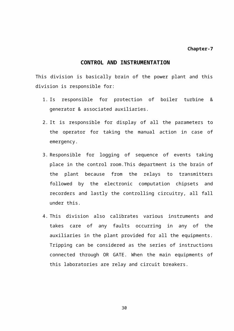
CONTROL AND INSTRUMENTATION
This division is basically brain of the power plant and this division is responsible for:
1. Is responsible for protection of boiler turbine & generator & associated auxiliaries.
2. It is responsible for display of all the parameters to the operator for taking the manual
action in case of emergency.
3. Responsible for logging of sequence of events taking place in the control room.This
department is the brain of the plant because from the relays to transmitters followed
by the electronic computation chipsets and recorders and lastly the controlling
circuitry, all fall under this.
4. This division also calibrates various instruments and takes care of any faults occurring
in any of the auxiliaries in the plant provided for all the equipments. Tripping can be
considered as the series of instructions connected through OR GATE. When the main
equipments of this laboratories are relay and circuit breakers.
Figure7.1ControlUnit
20
Chapter-8
TRANSFORMER
8.1 INTRODUCTION
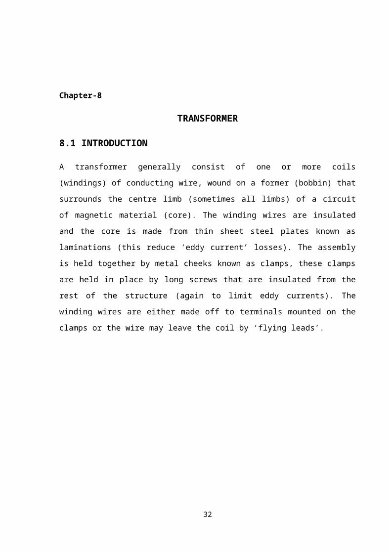
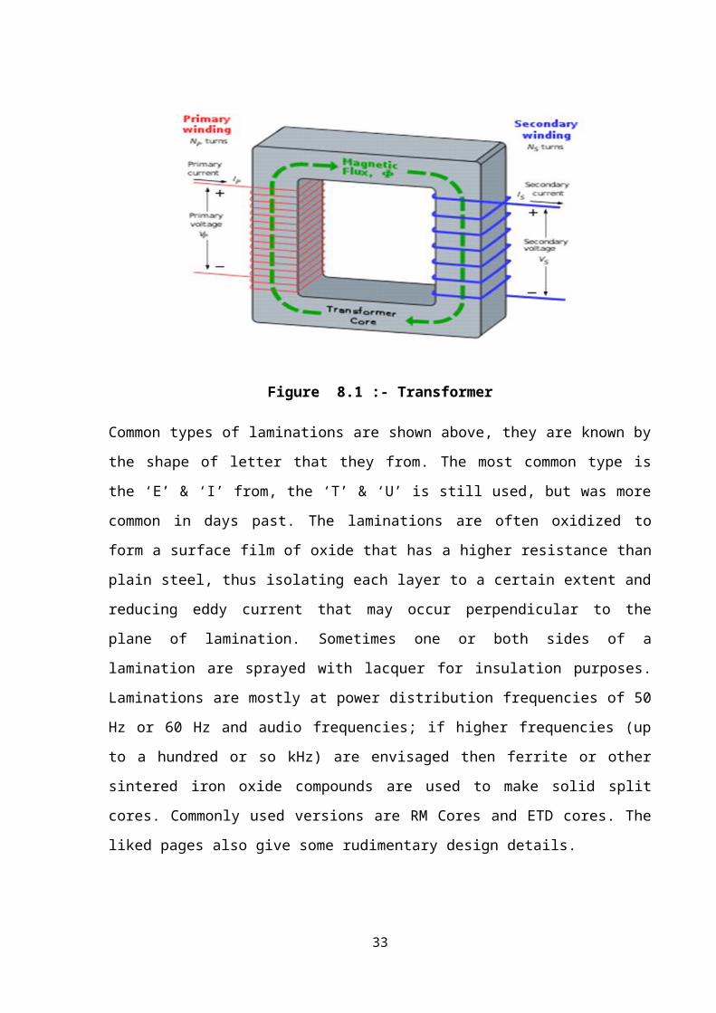
A transformer generally consist of one or more coils (windings) of conducting wire, wound
on a former (bobbin) that surrounds the centre limb (sometimes all limbs) of a circuit of
magnetic material (core). The winding wires are insulated and the core is made from thin
sheet steel plates known as laminations (this reduce ‘eddy current’ losses). The assembly is
held together by metal cheeks known as clamps, these clamps are held in place by long
screws that are insulated from the rest of the structure (again to limit eddy currents). The
winding wires are either made off to terminals mounted on the clamps or the wire may leave
the coil by ‘flying leads’.
Figure 8.1 :- Transformer
Common types of laminations are shown above, they are known by the shape of letter that
they from. The most common type is the ‘E’ & ‘I’ from, the ‘T’ & ‘U’ is still used, but was
more common in days past. The laminations are often oxidized to form a surface film of
oxide that has a higher resistance than plain steel, thus isolating each layer to a certain extent
21
and reducing eddy current that may occur perpendicular to the plane of lamination.
Sometimes one or both sides of a lamination are sprayed with lacquer for insulation purposes.
Laminations are mostly at power distribution frequencies of 50 Hz or 60 Hz and audio
frequencies; if higher frequencies (up to a hundred or so kHz) are envisaged then ferrite or
other sintered iron oxide compounds are used to make solid split cores. Commonly used
versions are RM Cores and ETD cores. The liked pages also give some rudimentary design
details.
The laminations when assembled from an interleaved ‘stack’ or ‘core’. The
interleaving is usually to avoid any gaps in the magnetic circuit as air is much less permeable
to magnetic flux than iron and steel.
The magnetic flux runs around the two side limbs and combines in the centre limb
which is twice the area of a single side limb, thus keeping flux density constant. The flux
lines that are indicated in red in the diagram at right would follow a slightly higher path near
the corner fixing holes, than my graphic skills can reproduce. It should be noticed that there is
practically zero flux in the centre of the long side and fixing holes or notches are common at
this point.
The ‘holes’ in the core are known as ‘windows’ or ‘window spaces’ and in an
assembled component they are filled by coils wound on a bobbin. Coil formers or bobbins are
of two types known as ‘plain’ or ‘split’, the one shown at left is plain and the other at right is
the split version.
Bobbins these days are mainly injection moulded in plastic, but larger ones often
have paxolin or balkanised paper board cheeks. Occasionally, transformers are constructed
with two or more independent bobbins, each having its own winding(s). this method of
construction is rare, but has it’s uses at very high voltages( above 3,000 volts). The windings
or coils that are wound around these bobbins can be either single coils or multiple ones.
Single coils are a type known as ‘Auto Transformers’ and we will not deal any further with
them as they are generally not applicable to the type of project that I get involved in.
Multiple coil types are known as ‘double wound’ and the windings fall into two
subdivisions… ‘Primary’ and ‘Secondary’ generally there is only one primary although it
may be divided into two or more portions. Secondary windings may be of any number. Coils
22
may be wound side by side on split bobbins or may be wound on top of one another with a
suitable insulation between. Generally the primary or input winding is completed first as the
innermost coil then layers of plastic or paper are placed over the completed primary and this
is then used as a base upon which further windings are made.
8.2 WINDING COIL
Two coils are shown, one crimson and one green, they indicate primary and secondary coils.
An alternating current flowing in the primary coil will cause an alternating flux in the core
which in turn couples with the secondary coil inducing an alternating voltage in it. If this
alternating voltage is applied to a load then an alternating current will result. The ratio of
turns between the primary and the secondary is proportionate (minus losses) to the voltages
on primary and secondary. The number of turns per volt is a function of the cross sectional
area of the magnetic circuit, the duty cycle and the allowable temperature rise. Eddy current
losses are constant and the fraction of primary current that is due to this cause is known as the
‘magnetizing current’/ the resistive losses in the windings, due to the current flowing is
generally known as ‘copper loss’ and is proportionate to the percentage of full load that the
device is run at.
8.3 POWER TRANSFORMER
Power transformers raise or lower the voltage as needed to serve the transmission or
distribution circuits.
Figure 8.2 :- Power Transformer
23
8.4 CURRENT TRANSFORMER
What is the purpose of a current transformer? If measures alternating current flowing through
a conductor. Since it is used to measure current, a current transformer is often classified as a
type of instrument transformer. One could measure the voltage drop across a known resistor.
This is okay for low current applications but is often impractical for high current applications.
The resistor consumes a lot of power (lowering efficiency) unless the resistor is very low in
value, in which case there may be very little voltage to measure. The resistor could be
excessively large. The resistor’s heat may affect the resistor value, thereby reducing the
accuracy of the measurement. A current transformer can accurately measure the alternating
current and put out a reasonable voltage, which is proportional to the current, but without as
much heat and size that an appropriate resistor would require. The current transformer can
perform its function with very little insertion loss into the conductor current being measured.
The current transformer also provides voltage isolation between the conductor and the
measuring circuitry. Proper function of a current transformer requires use of a load resistor.
The load resistor is often referred to as a “burden resistor”.
The best core structure for a current transformer in term of electrical performance is a
toroidal coil. Many toroidal current transformers have only one winding.This winding is
usually a “high turns” winding which functions as the secondary winding. In application, the
toroidal current transformer is slipped over an end of a high current wire or buss bar, which
conducts the primary current. Said wire or buss bar constitutes a one turn primary winding.
Split core current transformers are designed so that they can be assembled around a buss bar
without disconnecting the buss bar. “C”-cores and “U” core structure are commonly used for
split-core current transformers because they are relatively easy to take apart and put back
together around the buss bar. Historically, this has not been practical for toroidal coils, but
there are now some flexible toroids, which permits the “split-core” features of installing it
around a buss bar. They have limited application. Some printed circuit board applications will
utilize bobbin wound current transformer with two or more windings. One windings is an
integral part of the circuitry, while the other winding acts the secondary.
24
Chapter-9
BOILERS
A boiler is a closed vessel in which steam is produced from water by combustion of fuel.
Classification of boilers: -
1. Horizontal, vertical and inclined.
2. Fire tube and water tube.
9.1 WASTE HEAT RECOVERY BIOLER
Wagner-biro supplied boilers for anta combined cycle power plant known as waste heat
recovery boilers (WHRB), which are of non fired, dual pressure, forced circulation type. The
boiler has two different water/steam cycles known as high pressure system and low pressure
system. Each system has its own boiler drum and circulating pumps, and is feed by HP & LP
feed water pumps from a common feed water tank. The pressure and temperature of high
pressure super heated steam is 64 bar and 4900C and that of LP 6 bar and2060C.
The HP & LP steam from the three boiler from four common headers HP live steam
line, HP bypass line, LP live steam line and LP bypass line, the bypass line dump steam in
the condenser through the HP and LP bypass system. The HP steam drives the HP steam
turbine through stop valves and control valves. The LP steam after passing through stop
valves and control valves mixes with the HP turbine exhaust and drivers the gas turbine. This
dual system of operating utilizes the waste heat from the gas turbine with maximum
efficiency. From LP turbine steam enters the condenser where it get condensed to water with
the help of cooling water. Condenser is shell and tube, water flow through the tubes and
steam flow out side. The condensate get collected in hot well, from hot well it enters the feed
water tank through condensate extraction pump (3*50%).
25
Figure 9.1 :- Waste Heat Recovery Boiler
9.2 VARIOUS ACCESSORIES USED IN (WHRB) ARE
1. Super heater
Super heater is used to raise the temperature of steam above the saturation temperature by
absorbing the heat from flue gases which are coming from the diffuser.
Superheated steam has the following advantages: -
Steam consumption of the turbine is reduced. Erosion of turbine blade is eliminated.
Efficiency of steam plant is increased.
2. Evaporator
An evaporator is the component of a refrigeration system and is used to extract heat from the
chamber is to be kept at low temperature. The refrigerating liquid enters the evaporator,
26
absorbs latent heat from the chamber at constant pressure and comes out as a .
3. Economizer
The function of an economizer in a steam generating unit is to absorb heat from the flue gases
and add this as sensible heat to the feed water before the water enters the evaporative circuit
to the boiler .Advantages of economizer
The temperature between various parts of boiler is reduced which result in reduction of
stresses due to unequal expansion .Evaporative capacity of the boiler is increased. Overall
efficiency of the plant is increased.
4. Air Pre heater
An air pre heater is used to recover heat from flue gases. It is installed between the chimney
and economic.
5. De aerator
It is used to remove air from water as air carries oxygen which is corrosive in nature so to
protect the various parts of boiler from corrosion. We add the hydrazine (NH2=NH2) in to the
water which react with O2 and makes the pure water.
6. De super heater
It is used keep the temp. Of super heated steam constant. By spraying of some amount of
water over the superheated steam, we can decrease the temp. of steam to keep it at constant
temp. About 5250 C.
9.3 WHRB-SPECIFICATIN
1. Registration No : RJ-661-RJ 666
2. Constructor’s Name and Address : Wagner-Biro AG
a. Graz-Vienna, Austria
3. Manufactured For : National Thermal Power
a. Corporation (NTPC)
27
4. Contract No. : 01/CC/9505-001-01-1505
5. Type of Boiler : Forced Circulation
Overall Dimension of flue gas path
Width: 6, 4 m
Length: 18, 5 m
Height: 28,0 m
DESIGN DATA: HP-Part LP-Part Cond. Rec.
Design Pressure: 83 bar (g) 9 bar (g) 15 bar (g)
Intended working Pressure: 73 bar (g) 5, 5 bar (g) 11 bar (g)
Shop numbers of boiler: B1 B2 B3 B1 B2 B3 B1 B2 B3
2993 2994 2995 2990 2991 2992 2997 2998 2999
Total heating surface:
Water tubes: 59910m2 23859m2 6715m2
Super heater Tubes 8990 m2 584 m2 -
Steam and condensate 162, 6 t/h 39, 1 t/h 56 t/h
Mass flow:
Final temp. Of steam 488/5010C 2070C 1600C
Firing : Unfired –waste Heat temperature maz 5270 C
Year of Manufacture : 1988
Brief description of boiler : Waste heat recovery boiler with separate High and Low
28
9.4 DE MINERALISED WATER PLANT
In this section D.M. water is prepared for the purpose of steam generation. From the pre
treatment plant sump the water is transported to D.M. plant. The process of manufacturing is
dm water start form activated. The function of a cf. is to maintain level of the chlorine &
turbidity of water. The level of turbidity at inlet of the tank should be less than 2 ntu is naptha
lomateric Turbidity unit & turbidity at the outlet of the tank should be reduced to 0.5 nyu and
the level of the chlorine in the tank is 0.2 parts per million. After this water goes to weak acid
cation. This chamber is used to remove the temporary hardness of the water. The temporary
hardness present in the water is calcium carbonate & bicarbonates compounds. A special
resin is used for this purpose in the chamber. The resin used is 236-H. now water goes to the
STstrong acid cation. Function of this chamber is permanent hardness present in the water.
The permanent hardness compound present in the water is calcium, sodium & magnesium.
The resin used in this cylinder is H-220. After this an action is performed on the water to
remove the carbondi-oxide present in it & this is done by degrer. After the removal of CO2
from the water if goes to weak bare anion. This chamber removes weak anions present in the
water. Some of the weak anions present in water are silica, chlorates, nitrates & sulphates.
The main resin used is this cylinder is ira 90. When the weak anions are removed then the
strong base present in the water removed & this is done through strong base anion. Some of
the strong base present in the water are silica, chlorates & nitrates. The resin used in the
cylinder isffip. Now the water of strong base anion & strong acid caution are mixed & sent to
another cylinder called MImixed bed test This tank completely removes the ions present in
water. From here the ph of water is maintained so that it is neither more acidic nor more basic
& now water is stored in large tanks known as DM.
9.5 PRETREATMENT PLANT
Pre treatment plant is used to supply water for cooling of the various parts of the boiler &
condenser & for manufacturing of Mineralized water. D.M. water is used here because it is
pure and does not corrode the parts of the various components of boiler and condenser. The
process for pre treatment plant is as follows:
First of all the water from Right main canal is taken in to two reservoirs and from
these reservoirs the water is taken into the water house. Three pumps are used for pumping
29
this water into aerator. The function of aerator is to add oxygen to the water and to remove
dust particles from the water. From this; water goes to small reservoir, in which chlorination
is done to remove the algae, bacteria and other micro organisms present in the water. After
this the water goes to fore bay storage tank and from here, it goes to pump house where six
pumps are used. Three pumps are used to supply water to De-mineralized water & other three
are used to supply water to Effluent treatment plant. When the water reaches to the pre
treatment plant it is again passed from the aerator, to add oxygen to it. Now water rushes to
stilling chamber where chlorination is done to water for cleaning other micro organisms. The
flow of water at this point can be known by orifice flow meter. Now water is sent to two
clarifiers, from which anyone can be used at a time. In the clarifiers polymer & alum is added
in the centre of the tank purpose of addition of the alum is that it increase the size of small
impurities that are present in the water, but can’t be seen with help of our naked eye & the
function of the polymer is to bond that particles. Now the impurities can be easily removed.
The clarifier consists of three parts is inner most tank in which first water goes. The sludge
settles down & in taken to the sludge put & the clear water is taken to the gravity sand filters.
G.S.F. consists of four layers. First layer consists of large gravel. Second layer consists of
medium size gravel. On the top of that is small size gravel & at top most is present the layer
of sand. From these G.S.F’s the water gets more purified and it goes to D.M. plant.
30
CONCLUSION
I have studied about the power plant, especially in ANTA. Studied about gas power plant,
especially natural gas could be used for power generation in gas power plant. It is very
economical but less efficient. Mainly methane (CH4) is used as fuel. It is very profitable in
case of pollution. It is very less polluted. At place of fuel naphtha is used in alternate form.
But it is very costly and polluted. So it is used in very few shortages. This is very profitable
plant because it has combined cycle plant. According to combined cycle plant less
temperature gas will be recycled and used for generation of power. ANTA gas power plant
has four units in which three gas units and one steam unit. ANTA gas power plant has more
plants for reduction for pollution approximately 1.8 lac trees.
31
BIBLIOGRAPHY
1. “A Text Book Power Plant Engineering”,R.K. Rajput, 4th Edition.
2. “Power Plant Engineering”, A.K. Raja, 1st Edition.
3. “Steam &Gas Turbine and Power Plant Engineering” , Dr. R.Yadav ,7th Edition.
4. “NTPC reference guide”
5. “Notes given during training period”
32
33