electric propulsion - princeton universityalfven.princeton.edu/papers/encyclopedia.pdf · electric...
TRANSCRIPT

P1: ZBU Final Pages Qu: 00, 00, 00, 00
Encyclopedia of Physical Science and Technology EN005C-201 June 15, 2001 20:23
Electric Propulsion
Robert G. JahnEdgar Y. ChoueiriPrinceton University
I. Conceptual Organization and History of the Field
II. Electrothermal Propulsion
III. Electrostatic Propulsion
IV. Electromagnetic Propulsion
V. Systems Considerations
VI. Applications
GLOSSARY
Arcjet Device that heats a propellant stream by passing
a high-current electrical arc through it, before the pro-
pellant is expanded through a downstream nozzle.
Hall effect Conduction of electric current perpendicular
to an applied electric field in a superimposed magnetic
field.
Inductive thruster Device that heats a propellant stream
by means of an inductive discharge before the propel-
lant is expanded through a downstream nozzle.
Ion thruster Device that accelerates propellant ions by
an electrostatic field.
Magnetoplasmadynamic thruster Device that acceler-
ates a propellant plasma by an internal or external mag-
netic field acting on an internal arc current.
Plasma Heavily ionized state of matter, usually gaseous,
composed of ions, electrons, and neutral atoms or
molecules, that has sufficient electrical conductivity to
carry substantial current and to react to electric and
magnetic body forces.
Resistojet Device that heats a propellant stream by pass-
ing it through a resistively heated chamber before
the propellant is expanded through a downstream
nozzle.
Thrust Unbalanced internal force exerted on a rocket
during expulsion of its propellant mass.
THE SCIENCE AND TECHNOLOGY of electric
propulsion (EP) encompass a broad variety of strate-
gies for achieving very high exhaust velocities in order
to reduce the total propellant burden and corresponding
launch mass of present and future space transportation
systems. These techniques group broadly into three cat-
egories: electrothermal propulsion, wherein the propel-
lant is electrically heated, then expanded thermodynami-
cally through a nozzle; electrostatic propulsion, wherein
ionized propellant particles are accelerated through
an electric field; and electromagnetic propulsion, wherein
current driven through a propellant plasma interacts
with an internal or external magnetic field to provide a
Encyclopedia of Physical Science and Technology, Third Edition, Volume 5Copyright C© 2002 by Academic Press. All rights of reproduction in any form reserved. 125

P1: ZBU Final Pages
Encyclopedia of Physical Science and Technology EN005C-201 June 15, 2001 20:23
126 Electric Propulsion
stream-wise body force. Such systems can produce a range
of exhaust velocities and payload mass fractions an order
of magnitude higher than that of the most advanced chem-
ical rockets, which can thereby enable or substantially
enhance many attractive space missions. The attainable
thrust densities (thrust per unit exhaust area) of these sys-
tems are much lower, however, which predicates longer
flight times and more complex mission trajectories. In ad-
dition, these systems require space-borne electric power
supplies of low specific mass and high reliability, inter-
faced with suitable power processing equipment. Opti-
mization of EP systems thus involves multidimensional
trade-offs among mission objectives, propellant and power
plant mass, trip time, internal and external environmental
factors, and overall system reliability. An enduring inter-
national program of research and development of viable
electric thrusters has been in progress for several decades,
and over the past few years this has led to the increas-
ing use of a number of EP systems on commercial and
governmental spacecraft. Meanwhile, yet more advanced
EP concepts have matured to high credibility for future
mission applications.
I. CONCEPTUAL ORGANIZATIONAND HISTORY OF THE FIELD
A. Motivation
The stimulus for development of electrically driven
space propulsion systems is nothing less fundamen-
tal than Newton’s laws of dynamics. Since a rocket-
propelled spacecraft in free flight derives its only
acceleration from discharge of propellant mass, its equa-
tion of motion follows directly from conservation of
the total momentum of the spacecraft and its exhaust
stream:
mυ = mυe, (1)
where m is the mass of the spacecraft at any given time,
υ its acceleration vector, υe the velocity vector of the ex-
haust jet relative to the spacecraft, and m the rate of change
of spacecraft mass due to propellant-mass expulsion. The
product mυe is called the thrust of the rocket, T , and for
most purposes can be treated as if it were an external force
applied to the spacecraft. Its integral over any given thrust-
ing time is usually termed the impulse, I, and the ratio of
the magnitude of T to the rate of expulsion of propellant
in units of sea-level weight, mgo, has historically been la-
beled the specific impulse, Is = υe/go. If υe is constant
over a given period of thrust, the spacecraft achieves an
increment in its velocity, �υ, which depends linearly on
υe and logarithmically on the amount of propellant mass
expended:
�υ = υe lnmo
m f
, (2)
where mo and m f are the total spacecraft mass at the start
and completion of the acceleration period. Conversely, the
deliverable mass fraction, m f /mo, is a negative exponen-
tial in the scalar ratio �υ/υe:
m f
mo
= e−�υ/υe . (3)
Inclusion of significant gravitational or drag forces on
the flight of the spacecraft adds appropriate terms to Eq. (1)
and considerably complicates its integration, but it is still
possible to retain relation (3), provided that �υ is now
regarded as a more generalized “characteristic velocity
increment,” indicative of the energetic difficulty of the
particular mission or maneuver. However represented, the
salient point is simply that if the spacecraft is to deliver a
significant portion of its initial mass to its destination, the
rocket exhaust speed must be comparable to this charac-
teristic velocity increment. Clearly, for missions of large
�υ, the burden of thrust generation must shift from high
rates of ejection of propellant mass to high relative exhaust
velocities. Unfortunately, conventional chemical rockets,
whether liquid or solid, monopropellant or bipropellant,
are fundamentally limited by their available combustion
reaction energies and heat transfer tolerances to exhaust
speeds of a few thousand meters per second, whereas
many attractive space missions entail characteristic ve-
locity increments at least an order of magnitude higher.
Thus, some fundamentally difierent concept for the accel-
eration of propellant mass that circumvents the intrinsic
limitations of chemical thermodynamic expansion is re-
quired. Into this breech step the family of electric propul-
sion possibilities.
B. Conceptual Subdivision
So that propellant exhaust speeds in the range above
10,000 m/sec desirable for interplanetary flight and other
high-energy missions can be obtained, processes basically
different from nozzled expansion of a chemically reacting
flow must be invoked. More intense forms of propellant
heating may be employed, provided that the walls of the
rocket chamber and nozzle are protected from excessive
heat transfer. Alternatively, the thermal expansion route
may be bypassed completely by direct application of suit-
able body forces to accelerate the propellant stream. Either
of these options is most reasonably accomplished by elec-
trical means, which constitute the technology of electric
propulsion.

P1: ZBU Final Pages
Encyclopedia of Physical Science and Technology EN005C-201 June 15, 2001 20:23
Electric Propulsion 127
Historically, conceptually, and pragmatically, this field
has tended to subdivide into three categories:
1. Electrothermal propulsion, wherein the propellant is
heated by some electrical process, then expanded
through a suitable nozzle
2. Electrostatic propulsion, wherein the propellant is
accelerated by direct application of electrostatic
forces to ionized particles
3. Electromagnetic propulsion, wherein the propellant is
accelerated under the combined action of electric and
magnetic fields
Over their periods of development, each of these ap-
proaches has spawned its own array of technical special-
ties and subspecialties, its own balance sheet of advantages
and limitations, and its own cadres of proponents and de-
tractors, but in serious assessment, each has validly qual-
ified for particular niches of application, many of which
do not seriously overlap. Throughout the history of EP de-
velopment, the original subdivision of the field into elec-
trothermal, electrostatic, and electromagnetic systems has
remained useful, and this subdivision will be respected
through the balance of this article. It should be recog-
nized, however, that in virtually all practical systems, two
or even all three of these processes function in some con-
cert to accelerate, channel, and expand the propellant flow,
and in many cases it is the efficacy of this cooperation that
determines the utility of any given device.
The exhaust velocities attainable by these methods,
especially the latter two, are more than adequate for
many large-velocity-increment missions beyond the vi-
able chemical range. Indeed, some restraint of their υe
capability may be required because of their associated
“power supply penalty.” Clearly, each of these concepts
entails two functional components: the thruster itself and
an electric power supply to drive it. The latter adds mass,
m p, to the composite propulsion system in some propor-
tion to the power level of operation, P , which in turn scales
with the square of the exhaust velocity:
m p = αP =αT υe
2η=
αmυ2e
2η, (4)
where α is the specific mass of the power supply (mass
per unit power), and η is the efficiency with which the
thruster converts its input power to thrust power, T υe/2.
Since the requisite propellant mass scales inversely with
υe, it follows that for any given mission requirement, �υ,
there is an optimum υe that minimizes the sum of the
propellant mass and that of the requisite power supply.
Relation (4) also emphasizes the importance of utilizing
power systems of low specific mass and thrusters of high
conversion efficiency. Overlaid on all this is the evident
necessity for impeccable reliability of both components
of the system over long periods of unattended operation
in the space environment.
C. History of Effort
The attractiveness of EP for a broad variety of space trans-
portation applications was recognized by the patriarch of
modern rocketry, Robert H. Goddard, as early as 1906. His
Russian counterpart, Konstantin Tsiolkovskiy, proposed
similar concepts in 1911, as did the German Hermann
Oberth in his classic book on spaceflight in 1929 and the
British team of Shepherd and Cleaver in 1949. But the first
systematic and tutorial assessment of EP systems should
be attributed to Ernst Stuhlinger, whose book Ion Propul-
sion for Space Flight nicely summarizes his seminal stud-
ies of the 1950s.
The rapid acceleration of the U.S. space ambitions in
the 1960s drove with it the first coordinated research and
development programs explicitly addressing EP technol-
ogy. In its earliest phase, this efiort drew heavily on reser-
voirs of past experience in other areas of physical science
and engineering that had employed similar electrother-
mal, electrostatic, and electromagnetic concepts to their
own purposes, such as arc-heated wind tunnels and weld-
ing practice, cathode ray tubes and mass-spectroscopic
ion sources, and magnetohydrodynamic channel flows and
railguns. From these transposed technologies blossomed
a significant new component of the burgeoning space in-
dustry that concerned itself not only with the development
of viable electric thrusters, but also with the provision
of suitable electric power supplies and power condition-
ing equipment, major ground test facilities, and sophisti-
cated mission analyses of a smorgasbord of potential space
applications.
Following a sizable number of experimental flight tests,
EP entered its era of commercial application in the early
1980s, as resistojets became common options for sta-
tion keeping and attitude control on tens of commercial
spacecraft. In the early 1990s, electrothermal arcjets were
adopted for north–south station keeping (NSSK) of many
communication satellites in geosynchronous earth orbit
(GEO). The year 1994 saw the first use of electrostatic
ion thrusters for the NSSK of commercial satellites, and
the year 1998 their application on a planetary NASA mis-
sion. Although Hall thrusters have been used on Soviet
and Russian spacecraft since the mid-1970s, and there
have been a few applications of pulsed plasma thrusters,
electromagnetic thrusters are only now entering their era
of application on Western commercial spacecraft. In to-
tal, the number of electrically propelled spacecraft has
gone from single digits in the 1960s to double digits in
the 1970s and 1980s and has reached the triple-digit mark

P1: ZBU Final Pages
Encyclopedia of Physical Science and Technology EN005C-201 June 15, 2001 20:23
128 Electric Propulsion
in the late 1990s. A recent emphasis in research and de-
velopment has been the scaling down, in both physical
size and power level (<100 W), of many EP concepts
for future applications on micro-spacecraft. At the other
extreme, the prospect of energetic missions—with large
cargo and piloted payloads—to the planets, which stand to
benefit most from EP, remains futuristic until the required
high power levels (100 kW and above) become available
in space.
II. ELECTROTHERMAL PROPULSION
A. Overview
Electrothermal propulsion comprises all techniques
whereby the propellant is electrically heated in some
chamber and then expanded through a suitable nozzle to
convert its thermal energy to a directed stream that deliv-
ers reactive thrust power to the vehicle. Three subclasses
of this family may be denoted in terms of the physical
details of the propellant heating:
1. Resistojets, wherein heat is transferred to the
propellant from some solid surface, such as the
chamber wall or a heater coil
2. Arcjets, wherein the propellant is heated by an
electric arc driven through it
3. Inductively and radiatively heated devices, wherein
some form of electrodeless discharge or
high-frequency radiation heats the flow
Each of these strategies relieves some of the intrinsic
limitations of the chemical rocket in the sense that the pro-
pellant species may be selected for its propitious physical
properties independently of any combustion chemistry, but
heat transfer constraints and frozen flow losses (losses due
to unrecuperated energy “frozen” in the internal modes
and dissociation of the molecules) remain endemic.
The gross performance of any electrothermal thruster
can be crudely forecast by means of a rudimentary one-
dimensional energy argument that limits the exhaust speed
of the flow from a fully expanded nozzle to υe ≤√
2cpTc,
where cp is the specific heat at constant pressure per unit
mass of the propellant and Tc is the maximum tolerable
chamber temperature. Propellants of the lowest molecular
weight thus seem preferable, and indeed hydrogen might
at first glance appear optimum, but in practice its frozen
flow propensities and difficulty of storage compromise
its attractiveness. More complex molecular gases such as
ammonia and hydrazine, which dissociate into fairly low
effiective molecular weights and high specific heat gas
mixtures in the chamber, are currently more popular, but in
these cases also, frozen flow kinetics in the nozzle remain
important to performance.
B. Resistojets
In the resistojet subclass of devices, chamber temperature
is necessarily limited by the materials of the walls and/or
heater coils to some 3000◦K or less, and hence the ex-
haust velocities, even with equilibrated hydrogen, cannot
exceed 10,000 m/sec, which is nonetheless a factor of two
or three beyond that of the best chemical rockets. In con-
temporary practice, lower performance but more readily
space storable propellants, such as hydrazine and ammo-
nia, along with biowaste gases such as water vapor and
carbon dioxide, are more commonly employed because
of their overall system advantages.
Beyond the frozen flow kinetics, the major practical
challenge facing resistojet technology is retaining the in-
tegrity of the insulator and heater surfaces at the very high
temperatures the concept demands, while still minimiz-
ing the viscous and radiative heat losses that further de-
crease thruster efficiency. Since the mid-1960s, many con-
figurations of resistojet have been conceived, researched,
and developed to optimize these processes, and a few,
such as the flight-ready module shown schematically and
in the photograph in Fig. 1, have evolved to practical
space thrusters and been deployed on suitable missions.
A typical resistojet uses catalytically decomposed hy-
drazine as its propellant and achieves an exhaust velocity
of 3500 m/sec and a thrust of 0.3 N at an efficiency of 80%
when operating at a power level of 750 W.
From a system point of view, resistojets are particularly
attractive because they readily lend themselves to inte-
gration with previously developed and commonly used
propellant storage and flow management systems for hy-
drazine monopropellant thrusters. Another advantage is
their low operational voltage, which, unlike that in other
EP systems, does not require complex power processing.
For these reasons, and the fact that satellites in GEO often
have excess electrical power, resistojets were among the
first EP options to be used for the NSSK of communica-
tion satellites. While the earliest use of resistojets in space
dates to 1965 (the Air Force Vela satellites), their adop-
tion on commercial spacecraft did not start until the 1980
launch of the first satellites in the INTELSAT-V series. A
more recent application has been for orbit insertion, atti-
tude control, and deorbit of LEO satellites, including the
72 satellites in the Iridium constellation.
C. Arcjets
If an electrothermal thruster is to attain exhaust speeds
substantially higher than 10,000 m/sec, interior portions

P1: ZBU Final Pages
Encyclopedia of Physical Science and Technology EN005C-201 June 15, 2001 20:23
Electric Propulsion 129
FIGURE 1 Photograph and schematic of a flight-ready hydrazine
resistojet. [Courtesy of the Primex Corporation.]
of the propellant flow through the heating chamber must
reach temperatures as high as 10,000◦K, while being re-
strained from direct contact with the chamber and nozzle
walls. Thus, steep radial gradients in temperature must be
sustained, which renders the entire flow pattern explicitly
two-dimensional. The most effective and straightforward
means for achieving such profiles is by passing an elec-
tric arc directly through the chamber in some appropriate
geometry. Figure 2 shows a diagram and a photograph of
a prototypical thruster of this class, commonly called an
electrothermal arcjet. Direct currents of tens or hundreds
of amperes are passed through the gas flow between an
upstream conical cathode and a downstream annular an-
ode integral to the exhaust nozzle, generating a tightly
constricted arc column that reaches temperatures of sev-
eral tens of thousands of degrees on its axis. The incom-
ing propellant is usually injected tangentially, then swirls
around, along, and through this arc, expanding in the an-
ode/nozzle to average velocities of tens of thousands of
meters per second. Properly designed and operated, the
chamber and nozzle walls remain tolerably cool under the
steep radial gradients, and even the arc attachment regions
on the cathode and anode are somewhat protected by the
electrode sheath processes, even though the cathode tip
must reach incandescent temperatures to provide the req-
uisite thermionic emission of electron current.
Analytical models of thrusters of this type usually repre-
sent the arc in three segments: a cathode fall region, which
functions to heat the cathode tip and extract electrons from
it; an arc column, wherein ohmic heating hboxsustains the
necessary ionization against interior recombination and
radiation losses; and an anode fall region, wherein the arc
terminates in a diffuse annular attachment on the diverg-
ing nozzle wall, depositing thermal electron energy into
the body of the thruster. Heating of the propellant actually
occurs in two important modes: by direct passage of a core
portion of the flow through the arc itself, and by conduc-
tion and convection to the outer flow from the chamber and
nozzle walls, which themselves have been heated by radi-
ation from the arc column and by the anode attachment.
This latter, regenerative component rescues the efficiency
of the thruster somewhat from the detrimental frozen flow
losses associated with the failure of the hottest portion of
the core flow to recover much of the energy invested in its
ionization and dissociation. Aside from these frozen flow
losses, the efficiency also suffers from viscous effects,
nonuniform heat addition across the flow, and heat depo-
sition in the near-electrode regions due to voltage drops
in the electrode sheaths.
Arcjets on contemporary operational flights typically
use catalytically decomposed hydrazine as propellant and
operate at a power level of about 1.5 kW with an ex-
haust velocity between 5000 and 6000 m/sec and an effi-
ciency up to 40%. While ammonia, by virtue of its lower
molecular mass, can offer an exhaust velocity as high
as 9000 m/sec at the same power levels, the associated
complexity of the mass feeding system favors the use of
FIGURE 2 Photograph and schematic of a 1.5-kW arcjet in
operation. [Courtesy of the Primex Corporation.]

P1: ZBU Final Pages
Encyclopedia of Physical Science and Technology EN005C-201 June 15, 2001 20:23
130 Electric Propulsion
hydrazine. Since these arcjets operate at a voltage of about
100 V, which is generally higher than the spacecraft bus
voltage, dedicated power processing units, whose mass
can exceed that of the dry propulsion system, are required.
Starting with the first of the Telstar-4 series of GEO
communication satellites launched in 1993, hydrazine ar-
cjets have quickly gained acceptance as viable propulsion
options for NSSK. They represent the second evolution-
ary step, after resistojets, in the use of EP systems and
offer substantial propellant mass savings over all previ-
ous monopropellant propulsion options. Although a re-
cent test flight of a 30-kW ammonia arcjet (on the Air
Force ESEX spacecraft) has demonstrated the potential of
this higher power class of electrothermal propulsion for
more thrust-intensive missions such as orbit transfers and
primary propulsion maneuvers, the difficulty of providing
such high power in space, combined with the lifetime-
limiting problems of electrode erosion and whiskering
have so far delayed such applications.
D. Inductively and Radiatively Heated Devices
The most vulnerable elements of direct current arcjets are
the electrodes that transmit the high currents from the ex-
ternal circuit to the arc plasma, and their erosion ultimately
limits the operational lifetime of these thrusters. In ef-
forts to alleviate this basic problem, a number of more ex-
otic concepts for electrothermal propulsion have been pro-
posed and implemented, wherein the propellant is ionized
and heated by means of some form of electrodeless dis-
charge. These have varied widely in power levels, geome-
tries, propellant types, and densities and have utilized ap-
plied frequencies ranging from low radio frequency (RF)
to the microwave bands. In all cases, the strategy is to heat
the free electron component of the ionized propellant by
means of an applied oscillating electromagnetic field and
then to rely either on ambipolar difiusion to direct the ions
and neutrals along an appropriate exhaust channel (induc-
tive thrusters) or on collisional and radiative heating of
the neutral component by a sustained plasma upstream
of the throat of a diverging nozzle (microwave thrusters).
Devices of this class are thus hybrid electrothermal and
electrostatic and, indeed, since some of them also employ
magnetic fields to confine and direct the flow, may actually
embody all three classes of interaction.
Early enthusiasm for this class of accelerators was nec-
essarily tempered by the relatively low efficiency of RF
and microwave power generation technologies of that
time, which would have transcribed into intolerably mas-
sive space power supplies. More recent advances in solid-
state power processing have revived some of these con-
cepts, although none has yet been flight-tested. The most
mature of these concepts is currently a microwave elec-
trothermal thruster that operates with hydrogen, nitro-
gen, or ammonia at exhaust velocities ranging between
4000 m/sec and 12,000 m/sec and efficiencies as high as
60%, excluding the efficiency of the microwave source.
The microwave electrothermal thruster seems particularly
amenable to scaling to low powers. While most of the
recent development has been at the kilowatt level, scaled-
down prototypes operating efficiently at 100 W and below
have also been developed.
III. ELECTROSTATIC PROPULSION
A. Basic Elements
The fundamental thermal limitations on attainable exhaust
speeds and lifetimes associated with the heating and ex-
pansion processes of electrothermal accelerators can be
categorically circumvented if the propellant is directly ac-
celerated by an external body force. The simplest such
device, in concept, is the ion thruster, wherein a beam of
atomic ions is accelerated by a suitable electric field and
subsequently neutralized by an equal flux of free electrons.
The essential elements of such a thruster are sketched in
Fig. 3, where a collisionless stream of positive atomic ions,
liberated from some source, is accelerated by an electro-
static field established between the source surface and a
suitable permeable grid. Downstream of this region, elec-
trons from another source join the ion beam to produce
a stream of zero net charge, which exits the accelerator
at a speed determined not only by the net potential drop
between the ion source and the plane of effective neu-
tralization, but also by the charge-to-mass ratio of the ion
species employed.
A quick calculation, based on reasonable electrode di-
mensions, manageable applied voltages, and available ion
charge-to-mass ratios, indicates that extremely high ex-
haust speeds, well in excess of 105 m/sec, are readily
achievable. Indeed, given the power supply mass penalty,
which scales strongly with the exhaust velocity accord-
ing to Eq. (4), these devices tend to optimize their thrust
efficiency at too high an exhaust velocity for most near-
earth and interplanetary mission applications. A more
troublesome drawback, however, is that regardless of the
particular electrode configurations and propellant species
employed, thrusters of this class are severely limited in
their attainable thrust density by space-charge distortions
of the applied electric field pattern. Specifically, it can
readily be shown that the maximum ion current density
that can be sustained through a one-dimensional acceler-
ation gap d, across which is applied a voltage V, is
j =4ε
9
(
2q
M
)1/2V 3/2
d2, (5)

P1: ZBU Final Pages
Encyclopedia of Physical Science and Technology EN005C-201 June 15, 2001 20:23
Electric Propulsion 131
FIGURE 3 Ion thruster schematic.
where ε is the dielectric permittivity constant and q/M
is the ion charge-to-mass ratio, all in mks units. It then
follows that the maximum thrust density of the emitted
beam depends only on V/d:
T
A=
mυe
A=
j Mυe
q=
8ε
9
(
V
d
)2
, (6)
where A is the area of the exhaust jet, while the corre-
sponding exhaust speed depends only on q/M and V :
υe =
(
2qV
M
)1/2
. (7)
The thrust density and thrust power density that can be
conveyed on the exhaust beam for attainable values of
V, d , and q/M thus compute to rather small values, on
the order of a few newtons per square meter and 105 W
per square meter, respectively, at best. On the positive
side, the attainable thrust efficiency is essentially limited
only by the energetic cost of preparing the individual ions,
which should be a small fraction of their exhaust kinetic
energy. System optimization, therefore, involves a some-
what complex multidimensional trade-off among the ex-
haust speed, thrust density, efficiency, and power system
specific mass, for any given mission application.
B. Ion Thruster Technology
1. Ion Sources
In practice, the most amenable propellants for electro-
static thrusters have proven to be cesium, mercury, argon,
krypton, and most commonly xenon, and many possible
sources of such ions of the requisite efficiency, reliabil-
ity, and uniformity have been conceived and developed.
Of these, only three, the electron bombardment discharge
source, the cesium–tungsten surface contact ionization
source, and one form of RF discharge source, have sur-
vived to application.
The essential elements of the bombardment sources are
some form of cylindrical discharge chamber containing
a centerline cathode that emits electrons, a surrounding
anode shell, and a permeating azimuthal and radial mag-
netic field that constrains the electrons to gyrate within the
chamber long enough to ionize the injected propellant gas
and to direct it, once ionized, to extractor and accelera-
tor grids downstream. One contemporary implementation
of such a chamber is shown in Fig. 4. This particular de-
vice employs a hollow cathode electron source, wherein
is sustained a secondary discharge that facilitates electron
emission from the interior walls of the cathode cavity. The
magnetic field permeating the entire chamber is provided
by three ring magnets, empirically configured to estab-
lish a grossly diverging but doubly cusped field pattern
that optimizes the discharge for ionization and ion ex-
traction purposes. The magnitude of this field is adjusted
in concert with the anode–cathode voltage differential to
maximize the ionization efficiency and discharge stabil-
ity while minimizing the production of doubly charged
ions, which would be out of focus in the accelerator gap
and thus tend to erode the grids through high-energy sput-
tering. Typical values for xenon and mercury propellants
would be in the regimes of 0. 25 T and 30 V, respectively.
Slightly different chamber configurations and field values
have also been used successfully.
Contact ion sources rely on the difference between the
electronic work function of a metallic surface and the ion-
ization potential of alkali vapors to ionize the latter on
contact with the former. Very few metal–alkali combina-
tions have this requisite positive voltage differential, and
of these the combination of tungsten and cesium provides

P1: ZBU Final Pages
Encyclopedia of Physical Science and Technology EN005C-201 June 15, 2001 20:23
132 Electric Propulsion
FIGURE 4 Ring-cup ion thruster. [Courtesy of Colorado State University and NASA Glenn Research Center.]
the largest. The most common implementation has been
to force hot cesium vapor through a porous tungsten wafer
to enhance surface contact, but problems in degradation of
wafer porosity and recondensation of cesium vapor have
tended to compromise the ionization efficiency and life-
time of these sources.
The RF ionization sources currently favored in Western
Europe are similar in principle and configuration to the
U.S. electron bombardment sources, except that the dis-
charge is inductively driven RF rather than directly cou-
pled dc. While the efficiency and lifetime of these RF
sources seem competitive, they entail the complication of
RF modules in their power processing equipment. In Japan
another cathodeless ion thruster concept has been devel-
oped that uses a microwave source to create and sustain
the plasma through electron cyclotron resonance (ECR)
and offers some system and lifetime advantages.
2. Accelerator Grids
In virtually all classes of ion thruster, the positive ions are
extracted from the source and accelerated downstream by
a system of grids configured to achieve the desired ex-
haust velocity with minimum beam impingement. In U.S.
bombardment engines, for example, a double grid config-
uration is usually dished downstream as shown in Fig. 4
to improve its mechanical and thermal stability against
distortion. The upstream grid is maintained at a higher
positive potential than required by the desired exhaust
speed in order to enhance the ion extraction process and in-
crease the space-charge limited current density that can be
sustained. The downstream grid then reduces the exhaust
plane potential to the desired value. This “accel–decel”
scheme has the advantages of higher beam density at a
given net voltage and of reducing electron backstreaming
from the neutralized beam downstream.
The grid perforations are configured analytically and
empirically to focus the ion stream into an array of beam-
lets that pass through with minimum impingement. In this
process, the downstream surface of the discharge plasma
in the chamber acts as a third electrode, and since this
contour is not independent of the discharge characteris-
tics and applied grid voltages, it can be a source of some
instability. Further complications are introduced by the
small fractions of double ions or neutrals that find their
way into the beam and are henceforth out of focus and
free to bombard the grid surfaces.
3. Neutralizers
If the ion beam emerging from the downstream electrode
is not to stall on its own interior potential profile, it must

P1: ZBU Final Pages
Encyclopedia of Physical Science and Technology EN005C-201 June 15, 2001 20:23
Electric Propulsion 133
be electrostatically neutralized within a very few units of
grid spacing. This is typically achieved by provision of a
flux of electrons, usually from another hollow cathode dis-
charge, which fortuitously mix effectively within the ion
beam by means of a variety of microscopic and macro-
scopic internal scattering processes. Once so neutralized,
this plasma constitutes a downstream “virtual electrode”
that completes the axial potential pattern.
4. System Aspects and Application History
Although they are technically the most complex EP sys-
tems, ion engines like those outlined above and shown
in Fig. 5 have been the most thoroughly developed and
tested of all EP devices. Their appeal stems primarily from
their maturity, demonstrated long lifetime (>20,000 hr),
relatively low beam divergence (<20 deg) and high effi-
ciency (65%) at a useful exhaust velocity (30,000 m/sec),
and power levels between 200 and 4000 W. These advan-
tages are somewhat offset by low thrust density, system
complexity, and high-voltage requirements which trans-
late into power processing unit (PPU) specific masses
as high as 10 kg/kW. Their space-worthiness has been
demonstrated by more than a dozen U.S. and Soviet flight
tests, starting in 1962, which have provided guidance and
validation to ground-based research and development ef-
forts that have led to the optimization of their designs and
materials.
The first operational use of ion thrusters occurred in
1994 on the Japanese ETS-6 and COMETS satellites, for
which four 12-cm ion engines provided NSSK propulsion.
This was followed in 1997 by PAS-5, which inaugurated
the first U.S. commercial satellite bus to rely on ion propul-
sion for GEO station keeping.
FIGURE 5 A 30-cm bombardment ion engine. [Courtesy of
Hughes Aircraft Co.]
While ion engines compete well with other EP op-
tions for near-earth applications, their ability to operate
efficiently and reliably at even higher exhaust velocities
makes them ideally suited for energetic (i.e., high �υ)
deep-space missions, where long thrusting times can be
tolerated. In 1998, NASA ’s Deep Space 1 became the first
interplanetary mission to benefit from ion propulsion. On
its way to its encounter with asteroid Braille, the space-
craft used a xenon bombardment ion propulsion system
to provide the required �υ over 1800 hr of thrust, while
consuming only 12 kg of propellant and demonstrating in-
space performance within 1% of that measured in ground
tests. Various commercial and scientific missions using
ion propulsion are slated for launch in the next few years,
including the world’s first sample-and-return attempt from
an asteroid by the Japanese MUSES-C spacecraft.
C. Other Electrostatic Propulsion Concepts
Many of the complexities of ion bombardment sources,
multibeam focusing grids, electromagnets, and other sub-
systems of ion thrusters can be bypassed altogether if only
minute thrust levels are needed. Creating a high electric
field concentration at the lips of a capillary slit, as shown
in Fig. 6, allows direct ionization from the liquid phase of
a metal to be achieved by field emission, and the resulting
ion beam can be accelerated electrostatically to very high
velocities. Field emission electric propulsion (FEEP) de-
vices of this kind have evolved in Europe since the late
1970s and have unique characteristics and advantages. In
a typical FEEP device, cesium propellant from a small
reservoir is allowed to wet the inside of a 1-µm capillary
channel and form a free surface between the blade-edge
lips of the emitter. An electric field of a few kilovolts is
FIGURE 6 Schematic of a field emission electric propulsion
(FEEP) device.

P1: ZBU Final Pages
Encyclopedia of Physical Science and Technology EN005C-201 June 15, 2001 20:23
134 Electric Propulsion
applied between the emitter and an accelerator electrode,
and the resulting electric field concentrations at the slit
edges form protruding cusps, or “Taylor cones,” on the
edge of the liquid by means of the competition between
the electrostatic forces and surface tension. When the elec-
tric field reaches field emission levels (109 V/m), these
points become local ion emission sites. The extracted and
accelerated ion beams are subsequently neutralized by in-
jecting electrons from an appropriate source. For a typical
extraction voltage of 10 kV, the ion exhaust velocity is in
excess of 100,000 m/sec, the efficiency close to 100%, and
the thrust-to-power ratio about 16 µN/W. Although FEEP
thrusters with thrust levels as high as 5 mN have been de-
veloped by the European Space Agency, near-term appli-
cations are for missions requiring small and precise thrust.
While no such devices have yet flown, a number of mis-
sions are planned in the United States and Europe, includ-
ing systems associated with space-borne interferometers
for detection of gravitational waves, and missions requir-
ing fine pointing and formation flying of micro-spacecraft.
Since these FEEP devices are operated with cesium be-
cause of its high atomic mass, low ionization potential, low
melting point (28.4◦C), and good wetting capabilities, a
number of practical problems related to spacecraft plume
interactions and propellant contamination will need to be
resolved.
Another simple electrostatic thruster concept that has
the advantages over FEEP of higher thrust-to-power ratios
and the use of more benign propellants is the colloidal
thruster. It employs similar physical processes, except
that nonmetallic liquids are used and sub-micron-sized
charged particles (colloids) are produced and accelerated.
This yields specific impulses more compatible with near-
earth missions. Much of the work on colloidal thrusters
was carried out in the 1960s and identified limitations
on the achievable charge-to-mass ratios and the unifor-
mity of the the charge-to-mass distributions. The for-
mer transcribes to excessively large voltages (hundreds
of kilovolts) to attain the desirable exhaust velocities
(10,000 m/sec) and the latter results in large beam diver-
gences. Nonetheless, more recent research in Russia and in
the United States, driven by the advent of micro-spacecraft
missions, has returned colloidal electrostatic thrusters to
the arsenal of electric micropropulsion options.
IV. ELECTROMAGNETIC PROPULSION
A. Basic Concept
The third category of EP relies on the interaction of an
electric current pattern driven through a conducting pro-
pellant stream with a magnetic field permeating the same
FIGURE 7 Crossed-field electromagnetic thruster schematic.
region to provide the accelerating body force. Such sys-
tems can produce exhaust speeds considerably higher than
those of the electrothermal devices, and thrust densities
much larger than those of the electrostatic thrusters, but
are phenomenologically more complex and analytically
less tractable than either of these alternatives. The essence
of an electromagnetic thruster is sketched in Fig. 7, where
some electrically conducting fluid, usually a highly ion-
ized gas, is subjected to an electric field E and a mag-
netic field B, perpendicular to each other and to the fluid
velocity u. The current density j driven by the electric
field interacts with B to provide a streamwise body force
f = j × B that accelerates the fluid along the channel.
The process may alternatively be represented from a par-
ticulate point of view in terms of the mean trajectories
of the current-carrying electrons, which, in attempting to
follow the electric field, are turned downstream by the
magnetic field, transmitting their streamwise momentum
to the heavy particles in the stream by collisions and/or by
microscopic polarization fields. It is important to note that
in either representation, the working fluid, although highly
ionized, is macroscopically neutral, hence not constrained
in its mass flow density by space-charge limitations as in
the electrostatic accelerators.
B. Varieties
Unlike the electrothermal or electrostatic classes, which
offer only a few practical configurations, electromagnetic
acceleration presents myriad possibilities for implemen-
tation. The applied fields and internal currents may be
steady, pulsed, or alternating over a broad range of fre-
quencies; the B fields may be externally applied or induced
by the current patterns; and a broad variety of propel-
lant types, including liquids and solids, may be employed,
along with a host of channel geometries; electrode and
insulator configurations; means of injecting, ionizing, and

P1: ZBU Final Pages
Encyclopedia of Physical Science and Technology EN005C-201 June 15, 2001 20:23
Electric Propulsion 135
ejecting the propellants; and modes of delivery of the req-
uisite electrical power. As a result of ongoing research
and development since the late 1950s, a huge number of
such possible permutations of the electromagnetic propul-
sion concept have been studied, both experimentally and
theoretically, but only a few have survived the gauntlet
of requisite efficiency, reliability, range of performance,
and system compatibility to retain enduring technolog-
ical promise. Of these, most advanced are the steady
or quasi-steady magnetoplasmadynamic (MPD) thrusters,
the Hall-current accelerators, and the pulsed plasma
devices.
C. Magnetoplasmadynamic Thrusters
1. Operating Principles
As sketched in Fig. 8, the magnetoplasmadynamic thruster
(MPDT) is characterized by a coaxial geometry consti-
tuted by a central cathode, an annular anode, and some
form of interelectrode insulator. Gaseous propellants are
introduced into the upstream portion of the channel,
whereafter they are ionized by passage through an intense,
azimuthally uniform electric arc standing in the interelec-
trode gap. If the arc current is high enough, its associated
azimuthal magnetic field is sufficient to exert the desired
axial and radial body forces on the propellant flow, directly
accelerating it downstream and compressing it toward the
centerline into an extremely hot plasma just beyond the
cathode tip. Subsequent expansion of this plasma, along
with the direct axial acceleration, yields the requisite ex-
haust velocity.
Theoretically, these self-field accelerators can be rep-
resented in relatively simple continuum plasmadynamic
form or in more elaborate three-fluid plasma kinetic for-
mulations. Irrespective of their interior details, electro-
magnetic tensor analysis yields a generic thrust relation:
T =µJ 2
4π
(
lnra
rc
+ A
)
, (8)
FIGURE 8 Magnetoplasmadynamic thruster (MPDT) schematic.
where T is the total thrust, µ the vacuum magnetic per-
meability, J the total arc current, ra and rc the effective
arc attachment radii on the anode and cathode, and A a
parameter slightly less than unity that depends on the finer
details of the current attachment patterns on the electrodes.
Note that this relation, which generally agrees with exper-
iments, is independent of the mass flow rate and any other
properties of the propellant, thus the exhaust velocity must
scale as the ratio J 2/m. An important nondimensional
scaling parameter, ξ , which arises in several other empiri-
cal and theoretical contexts, including the onset of severe
erosion and the appearance of various modes of plasma
waves and instabilities, is calculated from the following
formula:
ξ ≡
J 2µ
m4π
(
lnra
rc
+ A
)
(2φi/M)1/2
1/2
, (9)
where the propellant is represented by its ionization poten-
tial φi and atomic mass M . Nominal MPDT operation is
achieved at ξ 1, while stable and low-erosion operation
is typically limited to ξ < 2. The lifetime of such devices
is limited by component erosion, most notably evapora-
tion of cathode material, and the performance is bounded
by losses associated with ionization and thermal energy
frozen in the flow as well as losses in the electrode sheaths.
The modeling and control of many loss mechanisms are
complicated by the presence of plasma turbulence due to
current-driven microinstabilities which can cause exces-
sive ionization and heating.
In space applications, the optimum power range of op-
eration will be delimited on the low side by the need to
ionize the propellant fully and to keep the electrode losses
relatively small compared with the thrust power. The up-
per power limit will be set either by tolerable erosion rates
and plasma instabilities, or by the realities of the overall
system, including the available space power source and as-
sociated heat rejection equipment. At megawatt power lev-
els and corresponding propellant flow rates, both ground
testing and space testing of these highly promising devices
present formidable technological and economic problems.
Indeed, at present there are no U.S. facilities capable of
long-term megawatt operation of steady-state MPDTs.
2. Present and Projected Capabilities
The MPDT has demonstrated its capability of provid-
ing specific impulses in the range of 1500–8000 sec with
thrust efficiencies exceeding 40%. High efficiency (above
30%) is typically reached only at high power levels (above
100 kW); consequently, the steady-state version of the
MPDT is regarded as a high-power propulsion option.

P1: ZBU Final Pages
Encyclopedia of Physical Science and Technology EN005C-201 June 15, 2001 20:23
136 Electric Propulsion
When the thruster is operated below 200 kW, the self-
induced magnetic field becomes only marginally sufficient
to provide the desired body force, and external fields are
frequently added to enhance performance in this range.
However, in its megawatt versions, the self-field MPDT
has the unique capability, among all developed electric
thrusters, of processing very high power levels in a simple,
compact, and robust device that can produce thrust den-
sities as high as 105 N/m2. These features have rendered
the steady-state MPDT particularly attractive for energetic
deep-space missions requiring high thrust levels, such as
piloted and cargo missions to Mars and the outer planets,
as well as for nearer-term orbit raising missions.
In addition to the present unavailability of high power
in space, the cathode erosion rates of the steady-state
MPDT (which can be as high as 0. 2 µg/C), have slowed
the evolution of steady-state MPDTs toward flight ap-
plications. A version of the steady-state MPDT, called
the lithium Lorentz-force accelerator (Li-LFA), shown in
Fig. 9, uses a multichannel hollow cathode and lithium
propellant to substantially reduce the cathode erosion
problem while significantly raising the thrust efficiency
at moderately high power levels. For example, a 200-kW
Li-LFA has demonstrated essentially erosion-free opera-
tion over 500 hr of steady thrusting at 12.5 N, 4000 sec
Is , and 48% efficiency. Since no other electric thruster
has yet shown such a high power processing capability,
the Li-LFA is at the forefront of propulsion options for
nuclear-powered deep-space exploration and heavy cargo
missions to the outer planets.
FIGURE 9 A 100-kW-class, lithium MPDT or Lorentz-force
accelerator.
In order to benefit from the advantages of MPD propul-
sion on today’s power-limited spacecraft, the MPDT can
also be operated in a quasi-steady (QS) pulsed mode using
flat-top high-current pulses long enough (>350 µsec) for
a steady-state current pattern to dominate the acceleration
process. The QS-MPDT can thus benefit from the high
efficiency associated with the instantaneous high power,
while drawing low steady-state power from the spacecraft
bus. This approach was adopted in the first MPDT to fly
as a propulsion system, a 1-kW-class QS-MPDT that op-
erated successfully in 1996 onboard the Japanese Space
Flyer Unit. (Previous MPDT spaceflight tests by Japan
and the Russia in 1975, 1977, 1980, and 1983 were purely
experimental.)
While no present operational spacecraft employ MPD
propulsion systems, ongoing research and development
activities in Russia and the United States on the Li-LFA,
and in Europe and Japan on the gas-fed MPDT, aim at fur-
ther improving the performance and lifetime of the steady-
state MPDT to a level that meets near-future advanced
propulsion needs.
D. Hall Thrusters
1. Operating Principles
If any electromagnetic accelerator is operated at low
enough plasma density or high enough magnetic field, the
current driven through it will divert from strict alignment
with the applied electric field to acquire a component in
the E × B direction—a form of the well-known “Hall ef-
fect” that derives from the ability of the current-carrying
electrons to execute significant portions of their cycloidal
motions in the crossed fields before transferring their mo-
mentum to the heavy particles. In extreme cases, this Hall-
current component can totally dominate the conduction or
“Lorentz” component.
Low-density Hall-current accelerators exploit this ef-
fect by providing channel and field geometries that lock
the plasma electrons into a nearly collisionless cross-
stream drift, which leaves the positive ions free to
accelerate downstream under a component of the ap-
plied electric field. In a sense, such devices are hybrid
electrostatic–electromagnetic accelerators with space-
charge neutralization automatically provided by the back-
ground of drifting electrons. Because the magnetic fields
in these devices are externally supplied, and because the
mass flow densities are intrinsically low, these thrusters
optimize their performance at considerably lower powers
than those of the self-field MPD devices.
2. Evolution and Present Capabilities
Coaxial Hall plasma accelerators were optimized in the
Former Russia during the late 1960s to the late 1990s,

P1: ZBU Final Pages
Encyclopedia of Physical Science and Technology EN005C-201 June 15, 2001 20:23
Electric Propulsion 137
where they attained efficiencies above 50%. Some of the
original work on Hall thrusters was also conducted in
the United States in the early and mid-1960s, but interest
in that accelerator waned in favor of more extensive ion
thruster development, until a vigorous revival of interest
began in the United States, Europe, and Japan in 1991.
Today’s Hall thrusters are sometimes referred to as
“closed-electron-drift” devices, given the azimuthal drift
of electrons that is common to all present variants of such
thrusters. The most common versions are the stationary
plasma thruster (SPT) (also termed the “magnetic layer
thruster”) and the anode layer thruster (ALT). The former
differs from the latter by its extended channel, the use
of insulator chamber walls, and the extent of the quasi-
neutral acceleration region, but both rely on the same ba-
sic principles for ionizing and accelerating the propellant.
A schematic of a Hall thruster of the SPT type is shown in
Fig. 10. Electrons from the cathode enter the chamber and
are subjected to an azimuthal drift in the crossed radial
magnetic and axial electric fields, wherein they undergo
ionizing collisions with the neutral propellant atoms (typ-
ically xenon) injected through the anode. While the mag-
FIGURE 10 Schematic of a Hall thruster with an extended insulator channel (stationary plasma thruster, or SPT),
showing the external cathode, the internal anode, the radial magnetic field, and typical particle trajectories.
netic field strength is sufficient to lock the electrons in an
azimuthal drift, it does not significantly affect the trajec-
tory of the ions, which are directly accelerated by the axial
electric field. An axial electron flux equal to that of the ions
reaches the anode due to a cross field mobility that often
exceeds classical values, and the same flux of electrons
is available from the cathode to neutralize the exhausted
ions. Quasi-neutrality is thus maintained throughout the
chamber and exhaust beam, and consequently no space-
charge limitation is imposed on the acceleration, which al-
lows relatively high thrust densities compared with those
of conventional electrostatic propulsion devices. Nomi-
nal operating conditions of a common flight module (e.g.,
the Russian SPT-100) operating with xenon are a 2- to
5-mg/sec mass flow rate; a 200- to 300-V applied voltage,
yielding a plasma exhaust velocity of 16,000 m/sec; and
a thrust of 40–80 mN, at efficiencies of about 50%.
3. Applications and Flight History
Hall accelerators of the closed-drift type are at present
the most commonly used plasma thrusters. Since 1972,

P1: ZBU Final Pages
Encyclopedia of Physical Science and Technology EN005C-201 June 15, 2001 20:23
138 Electric Propulsion
more than 110 Hall thrusters have been flown on Russian
spacecraft, and more than 52 thrusters remain in opera-
tion. They have also been used as plasma sources in active
space experiments. In view of their high specific impulse,
relatively high efficiency, and high thrust density, Hall
thrusters continue to be developed by industry and gov-
ernment for purposes of orbit insertion, attitude control,
and drag compensation. Because of the stringent require-
ments for trouble-free operation for many thousands of
hours, efforts to improve performance and lifetime are
currently under way in the United States, Russia, Europe,
and Japan. These include efforts to lower beam divergence
(which is typically between 30 and 40 degrees), to re-
duce electromagnetic interference (due to various types
of plasma oscillations), to lower erosion rates, and to in-
crease thrust efficiencies. Strides toward more efficient,
compact, and lightweight PPUs (with specific masses as
low as 5 kg/kW) are also being made.
E. Pulsed Plasma Thrusters
The power conservation strategy underlying quasi-steady
operation of MPDTs can be carried further by employ-
ing small power systems to drive plasma thrusters in
short (10-µsec) bursts of high instantaneous power
(10 MW). The energy involved is typically stored in
FIGURE 11 Various pulsed plasma thruster (PPT) configurations.
capacitor banks or inductor coils, then delivered rapidly
to the electrodes by some form of high-speed switch.
When a gas-fed pulsed plasma thruster (GF-PPT) is op-
erated in a predominantly electromagnetic mode, the ac-
celeration is achieved by “snowplow” action of a current
sheet driven by its self-induced Lorentz body force. Vari-
ous geometries that had been used in early thermonuclear
fusion experiments, including coaxial guns and linear and
theta pinch discharges (Fig. 11), have been modified into
propulsion configurations.
In the early and middle 1960s, GF-PPT systems were
developed that had efficiencies above 20% at specific im-
pulses near 5000 sec, using some 65 J of stored energy per
pulse, but since the main focus of EP research at that time
was on developing primary propulsion systems, GF-PPT
research and development ebbed by the end of that decade
due the need for massive capacitors and the energy and
lifetime requirements of the fast-acting valves required to
ensure high mass utilization efficiency.
However, one derivative of this concept survived in the
form of the simple ablative pulsed plasma thruster (APPT),
which promised to solve the mass utilization problem
without the use of valves, and to save system mass by shed-
ding the complex mass storage and control systems of their
gas-fed counterparts. In the APPT, shown schematically
in Fig. 12, the surface of a polymer block (most commonly

P1: ZBU Final Pages
Encyclopedia of Physical Science and Technology EN005C-201 June 15, 2001 20:23
Electric Propulsion 139
FIGURE 12 Schematic of an ablative pulsed plasma thruster
(APPT).
Teflon) is successively eroded by intermittent arc pulses
driven across its exposed face, and the ablated material is
accelerated by a combination of thermal expansion and
self-field electromagnetic forces.
The APPT has the claim of being the first EP system
to operate in orbit, when the 1964 Soviet Zond-2 space-
craft used six Teflon APPTs for sun pointing control. The
United States followed in 1968 with the LES-6 satellite,
which used four APPTs for east–west station keeping
(EWSK). Since then, APPTs have had a sporadic history
of application and, except for a small number of exper-
imental suborbital and orbital tests by the United States
and China, they have been used on only a series of five
U.S. Navy satellites launched in the late 1970s and early
1980s. It was not until the mid-1990s, in the context of
power-limited small satellites, that APPT research and
development were rekindled. Improved capacitor tech-
nology, combined with the simplicity of the APPT and
its propellant storage and feed system, and its capabil-
ity of providing small and precise impulses at high spe-
cific impulse and arbitrarily low spacecraft power, made
it suitable for many attitude-control chores on power-
limited small satellites. A small but growing number of
upcoming U.S. missions using APPTs have been planned,
which will use flight-ready modules such as that shown in
Fig. 13.
Two of the most severe defficiencies of APPTs, namely
their low efficiency (<15%) at low pulse energies and
spacecraft contamination by the polymer products in the
plume, have spurred some revival of their gas-fed pro-
genitors. GF-PPTs have the advantages of compatibility
with a wide range of propellants, cleaner exhaust, and
a wider scalability of performance. Recent advances in
low-inductance, high-frequency, and high-current pulsing
technologies have relieved the low mass utilization effi-
ciency problem that plagued the 1960s prototypes. Further
improvements of these devices will depend on a better un-
derstanding of the nature and scaling of the complex dis-
FIGURE 13 A flight-ready Teflon ablative pulsed plasma thruster
(APPT) module using two thrusters, positioned on the opposite
ends of the thrust axis. [Courtesy of the Primex Corporation.]
sipative mechanisms in such unsteady flows, and on the
the ability to control and abate the canting and instability
of the accelerating current sheets.
F. Inductive Thrusters
As with the electrothermal arcjets, the most vulnerable ele-
ments of all the electromagnetic thrusters described above
are the electrode surfaces. Hence there has been some on-
going interest in a variety of inductive possibilities that
require no electrodes directly exposed to the intense dis-
charge environment. Again, most of these concepts have
been transposed from other technologies, including pulsed
inductive discharges, traveling wave accelerators of var-
ious classes, RF fringe-field accelerators, and cyclotron
resonance devices. All involve inherently unsteady flows
over a wide range of operating frequencies, and all must
trade off the absence of electrode erosion against generally
poorer coupling efficiency between the external circuitry
and the accelerating propellant plasma. Like the inductive
electrothermal machines, their overall systems suffer from
the more complex and massive power processing equip-
ment needed to drive them, although some of this disad-
vantage has been ameliorated by recent improvements in
solid-state electronic technology, so that their future may
be somewhat brighter than their past.
V. SYSTEMS CONSIDERATIONS
A. Power Conditioning
Almost all electric thrusters, except resistojets, operate
at voltages larger than those provided by the standard
P1: ZBU Final Pages
Encyclopedia of Physical Science and Technology EN005C-201 June 15, 2001 20:23
140 Electric Propulsion
bus of solar-powered spacecraft. This necessitates the use
of power processing subsystems that transpose the pri-
mary power from the space-borne source to the requisite
voltages, currents, and duty cycles of the given thrusters.
The PPU can have much influence over the overall effi-
ciency, reliability, and mass of the total propulsion system.
Aside from voltage conditioning, each class of thruster
presents its own demands on the PPU. Many electrother-
mal arcs, for example, can develop negative slopes in
portions of their voltage–current characteristics that are
tantamount to negative impedance for the power source
and must be suitably ballasted if the arc is to be prop-
erly controlled. Ion thrusters require a broad range of
electrode voltages and currents for their discharge an-
odes, hollow cathodes, and accelerating grids and must be
protected against high-voltage shorts and insulator break-
downs. High-power MPD accelerators require huge cur-
rents at relatively low voltages, and their unsteady versions
present an additional overlay of energy storage and pro-
cessing requirements. Almost all electric thrusters require
some ignition mechanism that inevitably complicates the
power package.
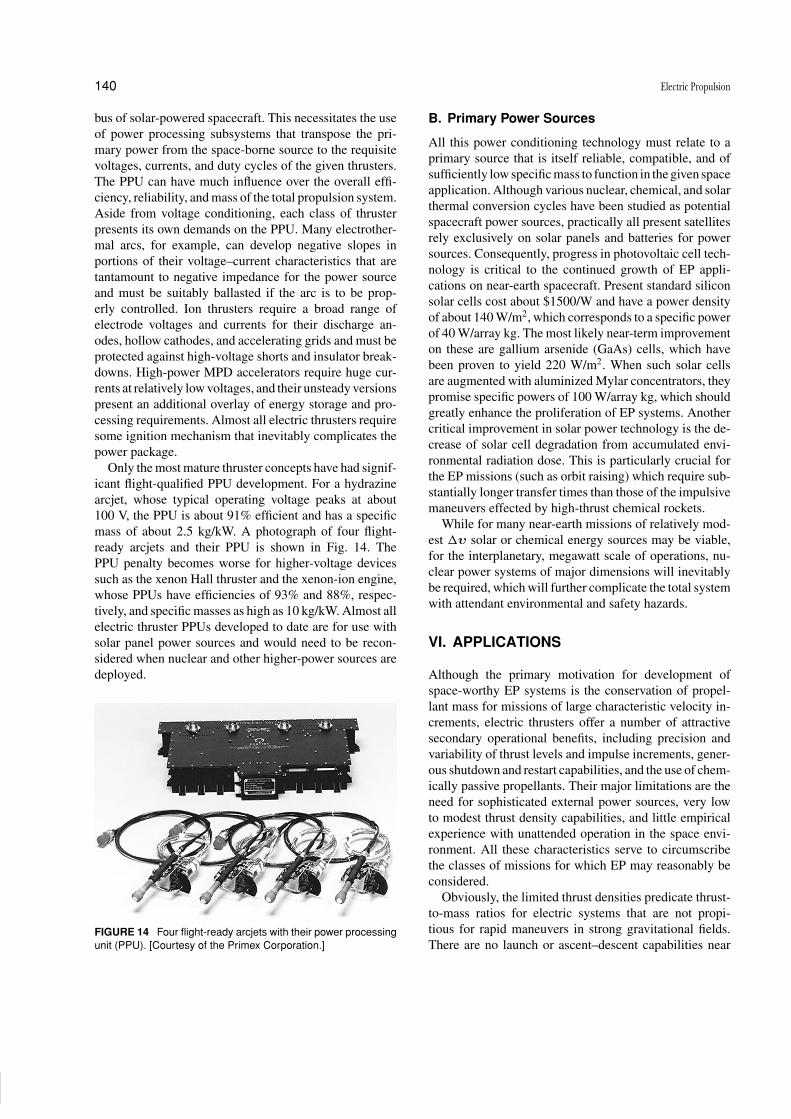
Only the most mature thruster concepts have had signif-
icant flight-qualified PPU development. For a hydrazine
arcjet, whose typical operating voltage peaks at about
100 V, the PPU is about 91% efficient and has a specific
mass of about 2.5 kg/kW. A photograph of four flight-
ready arcjets and their PPU is shown in Fig. 14. The
PPU penalty becomes worse for higher-voltage devices
such as the xenon Hall thruster and the xenon-ion engine,
whose PPUs have efficiencies of 93% and 88%, respec-
tively, and specific masses as high as 10 kg/kW. Almost all
electric thruster PPUs developed to date are for use with
solar panel power sources and would need to be recon-
sidered when nuclear and other higher-power sources are
deployed.
FIGURE 14 Four flight-ready arcjets with their power processing
unit (PPU). [Courtesy of the Primex Corporation.]
B. Primary Power Sources
All this power conditioning technology must relate to a
primary source that is itself reliable, compatible, and of
sufficiently low specific mass to function in the given space
application. Although various nuclear, chemical, and solar
thermal conversion cycles have been studied as potential
spacecraft power sources, practically all present satellites
rely exclusively on solar panels and batteries for power
sources. Consequently, progress in photovoltaic cell tech-
nology is critical to the continued growth of EP appli-
cations on near-earth spacecraft. Present standard silicon
solar cells cost about $1500/W and have a power density
of about 140 W/m2, which corresponds to a specific power
of 40 W/array kg. The most likely near-term improvement
on these are gallium arsenide (GaAs) cells, which have
been proven to yield 220 W/m2. When such solar cells
are augmented with aluminized Mylar concentrators, they
promise specific powers of 100 W/array kg, which should
greatly enhance the proliferation of EP systems. Another
critical improvement in solar power technology is the de-
crease of solar cell degradation from accumulated envi-
ronmental radiation dose. This is particularly crucial for
the EP missions (such as orbit raising) which require sub-
stantially longer transfer times than those of the impulsive
maneuvers effected by high-thrust chemical rockets.
While for many near-earth missions of relatively mod-
est �υ solar or chemical energy sources may be viable,
for the interplanetary, megawatt scale of operations, nu-
clear power systems of major dimensions will inevitably
be required, which will further complicate the total system
with attendant environmental and safety hazards.
VI. APPLICATIONS
Although the primary motivation for development of
space-worthy EP systems is the conservation of propel-
lant mass for missions of large characteristic velocity in-
crements, electric thrusters offer a number of attractive
secondary operational benefits, including precision and
variability of thrust levels and impulse increments, gener-
ous shutdown and restart capabilities, and the use of chem-
ically passive propellants. Their major limitations are the
need for sophisticated external power sources, very low
to modest thrust density capabilities, and little empirical
experience with unattended operation in the space envi-
ronment. All these characteristics serve to circumscribe
the classes of missions for which EP may reasonably be
considered.
Obviously, the limited thrust densities predicate thrust-
to-mass ratios for electric systems that are not propi-
tious for rapid maneuvers in strong gravitational fields.
There are no launch or ascent–descent capabilities near

P1: ZBU Final Pages
Encyclopedia of Physical Science and Technology EN005C-201 June 15, 2001 20:23
Electric Propulsion 141
planetary surfaces, and even outer orbit transfer exercises
can be performed only very slowly over gentle spiral tra-
jectories. Thus, near-planet applications will be limited
to those attitude-control, station-keeping, drag-reduction,
and modest orbit-changing functions (such as orbit phase
changes in LEO constellations) where the minuteness and
precision of thrust, propellant conservation, and long life-
time give them superiority over chemical options. Many
such applications have been recognized and evaluated, and
in several cases appropriate electric systems have been, or
soon will be, deployed.
In the domain of interplanetary flight, however, EP of-
fers much more substantial advantages over chemical sys-
tems, which extend in several important cases to enabling
missions that simply could not be performed by means
of any other reasonably projected propulsion technology.
These include heavy cargo and/or piloted missions to Mars
and the outer planets and many unpiloted probes beyond
the solar system and out of the ecliptic plane.
Comparison of electric and chemical systems for any
ambitious mission, piloted or unpiloted, reveals that the
basic dynamical distinction is between essentially impul-
sive thrust increments provided by the latter and much
more protracted, lower-level thrust profiles necessarily,
and in some cases advantageously, provided by the former.
Analytical optimization of extended variable thrust trajec-
tories for interplanetary transportation is a complex task,
far from fully rendered in contemporary mission analy-
ses. Superimposed on the strictly dynamical aspects are a
host of systemic considerations, such as the importance of
flight time to crew, other payload considerations, internal
and external environmental hazards, utility of the power
supply at destination, fraction of payload to be returned,
secondary mission goals in flight, human and structural
compatibility with flight maneuvers such as aerobraking
and swingby, and in-flight adjustment, service, and emer-
gency return capabilities. Since many of these, especially
those involving human factors, currently have inadequate
fundamental databases and theoretical representations, the
composite mission assessments are shaky, at best, and
much more sophisticated analyses will be required before
definitive mission projections.
Finally, as already mentioned, before any such ambi-
tious EP missions can seriously be contemplated, nonso-
lar alternatives for high-power sources in space must be
developed. For mostly political reasons, plans for deploy-
ment of nuclear high-power sources in space have so far
failed to materialize, and consequently the use of electric
thrusters for primary propulsion in energetic missions has
had a cyclical history of false starts and disappointments.
Indeed, the recent vigorous rejuvenation of the field of
electric propulsion can be attributed, at least in part, to
a conscious shift in emphasis away from the high-power
missions envisaged during the 1960s and 1970s toward
the less ambitious but more realistic power-limited small
satellites of today. Now that many EP systems have en-
tered the mainstream of astronautic technology, their role
in helping to expand human ambition beyond the inner
part of the solar system, although still dependent on the
hitherto unrealized development of high-power sources,
is perhaps on more credible ground.
SEE ALSO THE FOLLOWING ARTICLES
LIQUID ROCKET PROPELLANTS • RAMJETS AND SCRAM-
JETS • ROCKET MOTORS, HYBRID • ROCKET MOTORS,
LIQUID • ROCKET MOTORS, SOLID • SOLID PROPELLANTS
• SPACECRAFT CHEMICAL PROPULSION • SPACECRAFT
DYNAMICS
BIBLIOGRAPHY1
Jahn, R. G. (1968). “Physics of Electric Propulsion,” McGraw-Hill, New
York.
Stuhlinger, E. (1964). “Ion Propulsion for Space Flight,” McGraw-Hill,
New York.
1A special issue of the Journal of Propulsion and Power, Vol. 14,
No. 6, 1998, contains review articles on general EP, EP for solar system
exploration, ion thruster development, PPTs, Hall thrusters, MPDTs,
high-power arcjets, and field emission micropropulsion.