design requirements hvdc - usaid sari/energy...
TRANSCRIPT
Design Of HVDC System
Page 1 23.08.2011 ET-PS Energy Transmission
Objectives for Design Of HVDC SystemSystem
Maximum reliability / availability y y High Flexibility. Low Maintenance Safety
Page 2 23.08.2011 ET-PS Energy Transmission
System Consideration for Design Of HVDC SystemHVDC System
Outage risks for planning High capacity Links.g p g g p y Inter-tripping Schemes to take care of HVDC pole/Bipole
outages. Minimum and Maximum Fault levels. Reactive Power Exchange with System.
N d f E t l D i t Need for External Dynamic support. Load rejection Over voltages (TOV). Recovery from AC and DC faults Recovery from AC and DC faults. Commutation failure performance.
Page 3 23.08.2011 ET-PS Energy Transmission
COMMUNICATIONCOMMUNICATION
Highly reliable and effective telecommunication systemshould be available between the terminals.
Telecommunication link can be either PLCC or OPGWTelecommunication link can be either PLCC or OPGW.
Optical Ground Wire (OPGW) can be installed on one ofth k f th HVDC lithe peaks of the HVDC line.
Page 4 23.08.2011 ET-PS Energy Transmission
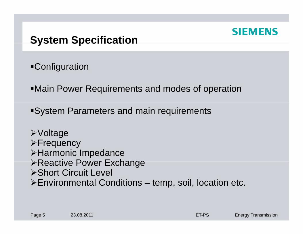
System SpecificationSystem Specification
Configuration
Main Power Requirements and modes of operation
System Parameters and main requirements
VoltageVoltageFrequencyHarmonic ImpedanceReactive Power ExchangeReactive Power ExchangeShort Circuit LevelEnvironmental Conditions – temp, soil, location etc.
Page 5 23.08.2011 ET-PS Energy Transmission
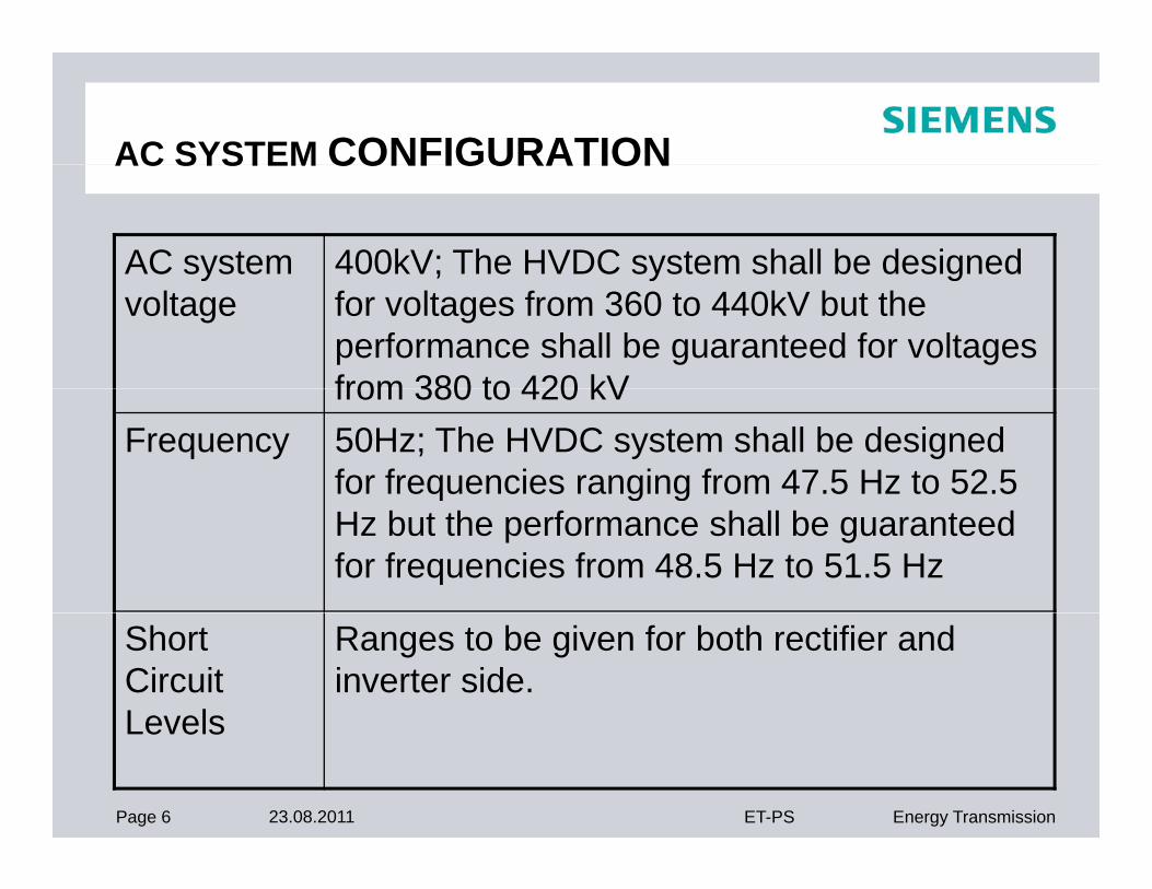
AC SYSTEM CONFIGURATIONAC SYSTEM CONFIGURATION
AC system 400kV; The HVDC system shall be designed yvoltage
; y gfor voltages from 360 to 440kV but the performance shall be guaranteed for voltages from 380 to 420 kVfrom 380 to 420 kV
Frequency 50Hz; The HVDC system shall be designed for frequencies ranging from 47.5 Hz to 52.5 g gHz but the performance shall be guaranteed for frequencies from 48.5 Hz to 51.5 Hz
Short Circuit Levels
Ranges to be given for both rectifier and inverter side.
Page 6 23.08.2011 ET-PS Energy Transmission
Levels
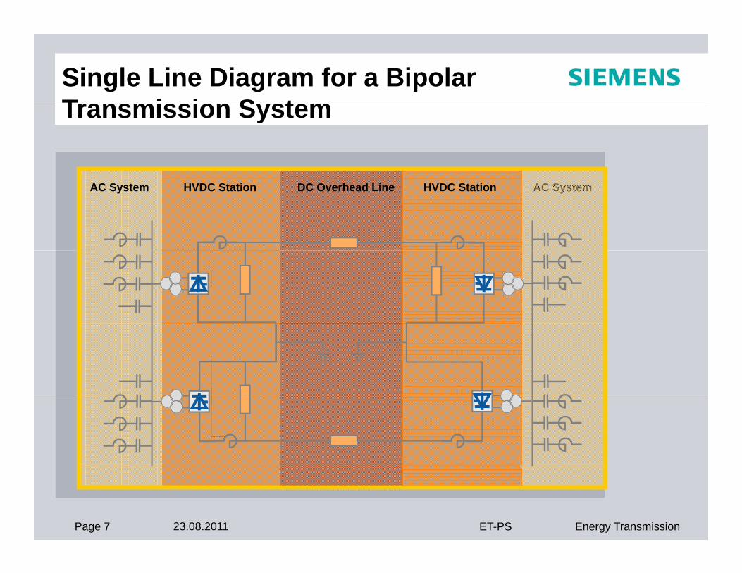
Single Line Diagram for a Bipolar Transmission SystemTransmission System
AC SystemAC System HVDC Station DC Overhead Line HVDC Station
Page 7 23.08.2011 ET-PS Energy Transmission
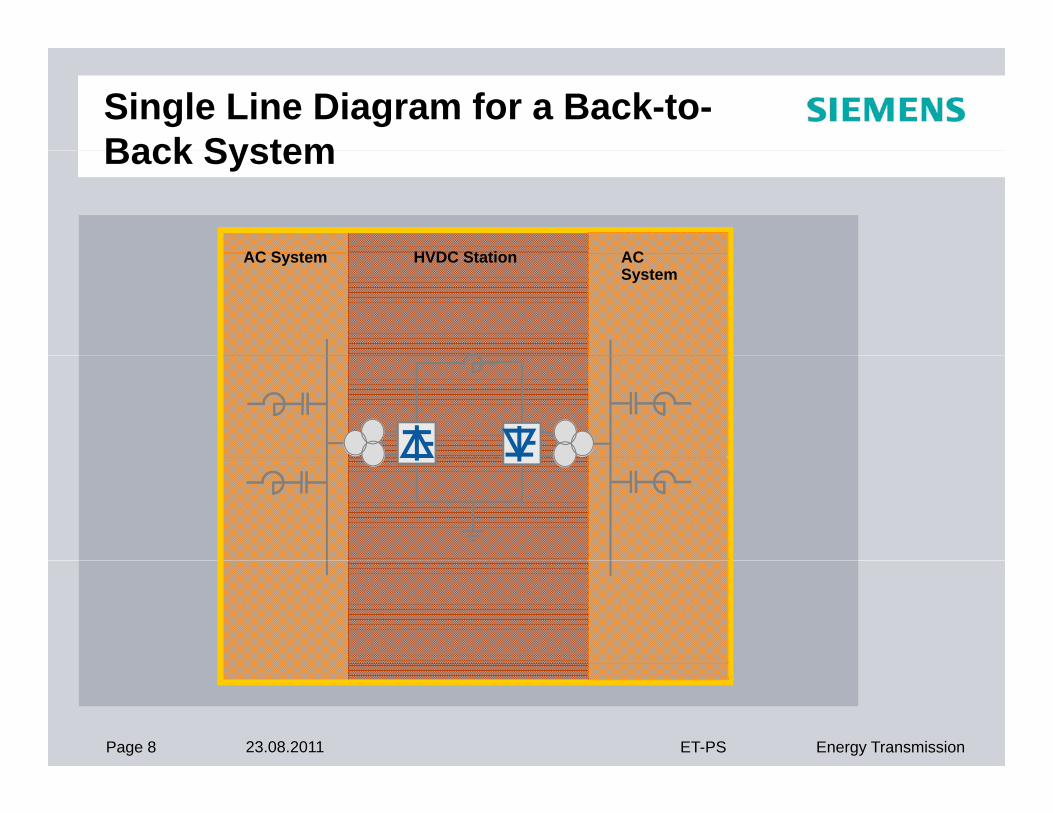
Single Line Diagram for a Back-to-Back SystemBack System
AC S t HVDC St ti ACAC System HVDC Station AC System
Page 8 23.08.2011 ET-PS Energy Transmission
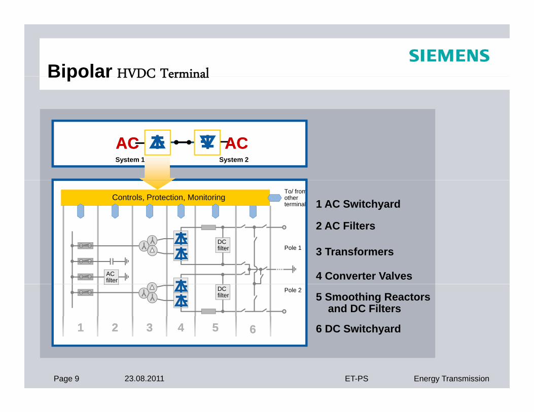
Bipolar HVDC TerminalBipolar HVDC Terminal
ACSystem 1 System 2
ACACACAC
1 AC Switchyard
2 AC Filters
Controls, Protection, MonitoringTo/ fromotherterminal
3 Transformers
4 Converter Valves
Pole 1
ACfilter
DCfilter
5 Smoothing Reactorsand DC Filters
6 DC Switchyard
Pole 2
6611 22 33 44 55
DCfilter
Page 9 23.08.2011 ET-PS Energy Transmission
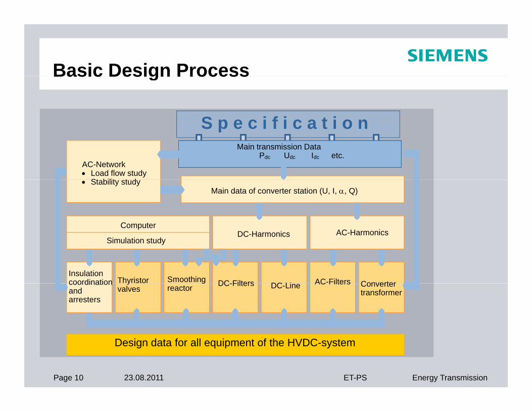
Basic Design ProcessBasic Design Process
S p e c i f i c a t i o nS p e c i f i c a t i o n Main transmission Data
Pdc Udc Idc etc.AC-Network Load flow study
St bilit t d
Simulator Computer
Stability studyMain data of converter station (U, I, , Q)
DC H i AC Harmonics
Insulationcoordination Thyristor
Simulation study
DC FiltersSmoothingDC Li AC-Filters Converter
DC-Harmonics AC-Harmonics
coordinationand arresters
yvalves
DC-Filtersgreactor DC-Line AC Filters Converter
transformer
Page 10 23.08.2011 ET-PS Energy Transmission
Design data for all equipment of the HVDC-system
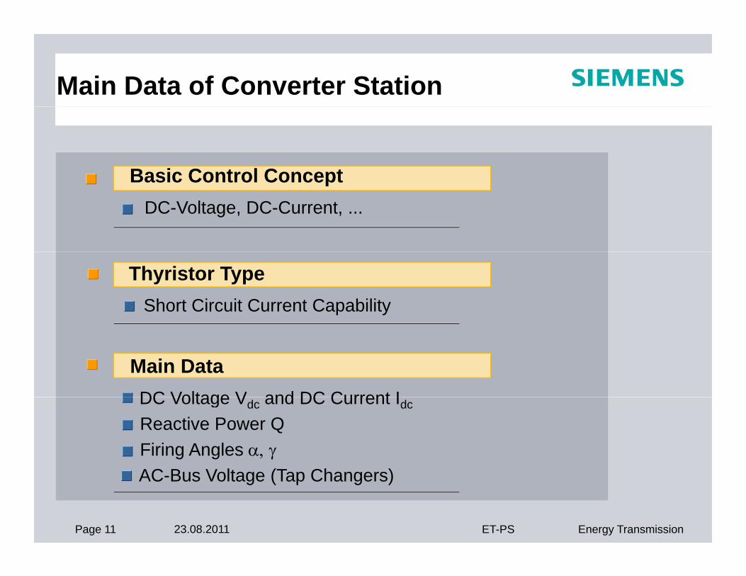
Main Data of Converter Station
Basic Control ConceptBasic Control ConceptDC-Voltage, DC-Current, ...
Thyristor TypeShort Circuit Current Capability
Main DataDC Voltage V and DC Current IDC Voltage Vdc and DC Current Idc
Reactive Power QFiring Angles AC B V lt (T Ch )
Page 11 23.08.2011 ET-PS Energy Transmission
AC-Bus Voltage (Tap Changers)
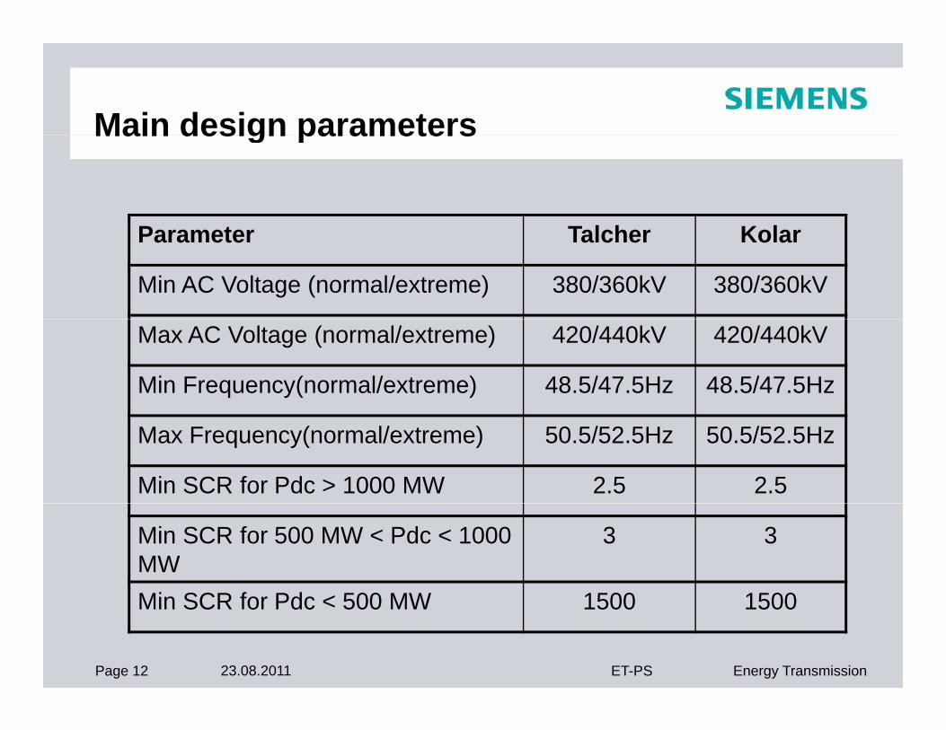
Main design parametersMain design parameters
P t T l h K lParameter Talcher Kolar
Min AC Voltage (normal/extreme) 380/360kV 380/360kV
Max AC Voltage (normal/extreme) 420/440kV 420/440kV
Min Frequency(normal/extreme) 48.5/47.5Hz 48.5/47.5Hz
Max Frequency(normal/extreme) 50.5/52.5Hz 50.5/52.5Hz
Min SCR for Pdc > 1000 MW 2.5 2.5
Min SCR for 500 MW < Pdc < 1000 MW
3 3
Mi SCR f Pd < 500 MW 1500 1500
Page 12 23.08.2011 ET-PS Energy Transmission
Min SCR for Pdc < 500 MW 1500 1500
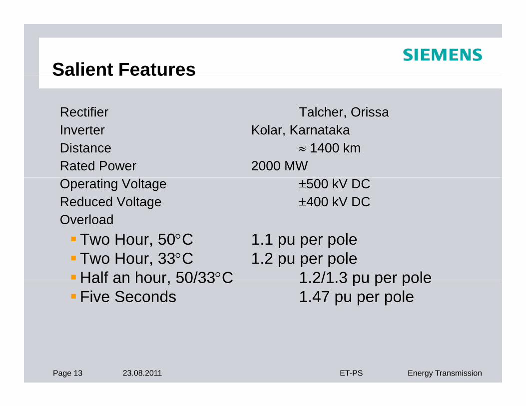
Salient FeaturesSalient Features
Rectifier Talcher, OrissaI t K l K t kInverter Kolar, KarnatakaDistance 1400 kmRated Power 2000 MWOperating Voltage 500 kV DCReduced Voltage 400 kV DCOverloadTwo Hour, 50C 1.1 pu per poleTwo Hour, 33C 1.2 pu per poleHalf an hour 50/33C 1 2/1 3 pu per poleHalf an hour, 50/33 C 1.2/1.3 pu per poleFive Seconds 1.47 pu per pole
Page 13 23.08.2011 ET-PS Energy Transmission
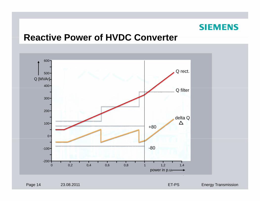
Reactive Power of HVDC ConverterReactive Power of HVDC Converter
600
400
500
Q [MVAr]
Q rect.
200
300
Q filter
0
100delta Q
+80
-200
-100
0 0 2 0 4 0 6 0 8 1 1 2 1 4
-80
Page 14 23.08.2011 ET-PS Energy Transmission
power in p.u.0 0,2 0,4 0,6 0,8 1 1,2 1,4
Reactive PowerReactive Power
R ti t ll t t t ti l lReactive power controller operates at station level
Reactive power requirements are met byAC h i filAC harmonic filtersCapacitor banks and reactors
Sizing of RP elements is influenced by
The reactive power exchange capabilities of the ac system at given dc power levelReactive power consumption of converter at given dc
power level
Page 15 23.08.2011 ET-PS Energy Transmission
… contd
Reactive PowerReactive Power
Various sub-banks can be connected either in automatic or manual modeTwo closed loop automatic control modes are possibleAC Voltage controlReactive power exchange controlSwitching hierarchy isSwitching hierarchy isAC voltageHarmonic performanceHarmonic performanceReactive power exchange
…contd
Page 16 23.08.2011 ET-PS Energy Transmission
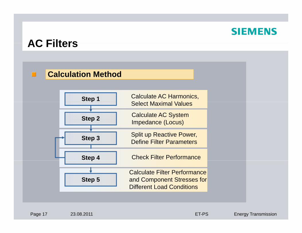
AC FiltersAC Filters
C l l ti M th dCalculation Method
Step 1 Calculate AC Harmonics,S l t M i l V l
Step 2 Calculate AC SystemImpedance (Locus)
pSelect Maximal Values
Step 3 Split up Reactive Power,Define Filter Parameters
Step 4 Check Filter Performance
Step 5Calculate Filter Performanceand Component Stresses forDifferent Load Conditions
p
Page 17 23.08.2011 ET-PS Energy Transmission
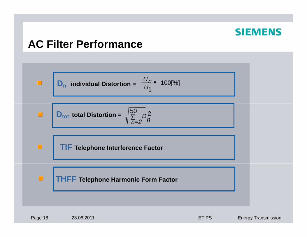
AC Filter PerformanceAC Filter Performance
Dn individual Distortion = 100[%]1
UnU
Dtot total Distortion = 50 2n=2 nD
TIF Telephone Interference Factor
THFF Telephone Harmonic Form Factor
Page 18 23.08.2011 ET-PS Energy Transmission
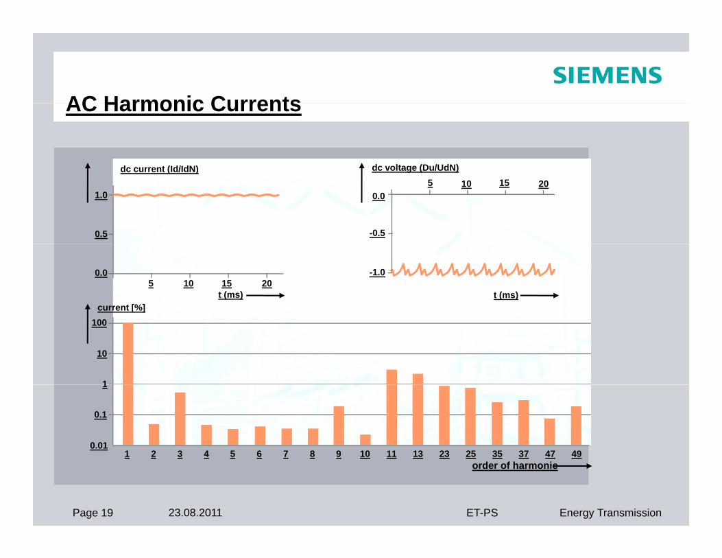
AC Harmonic CurrentsAC Harmonic Currents
dc current (Id/IdN) dc voltage (Du/UdN)( )
1.0
0.5
0.0
-0.5
5 10 15 20
0.0 -1.05 10 15 20
t (ms)current [%]
t (ms)
100
1
10
1 2 3 4 5 6 7 8 9 10 11 13 23 25 35 37 47 49
1
0.1
0.01
Page 19 23.08.2011 ET-PS Energy Transmission
1 2 3 4 5 6 7 8 9 10 11 13 23 25 35 37 47 49order of harmonic

Page 20 23.08.2011 ET-PS Energy Transmission
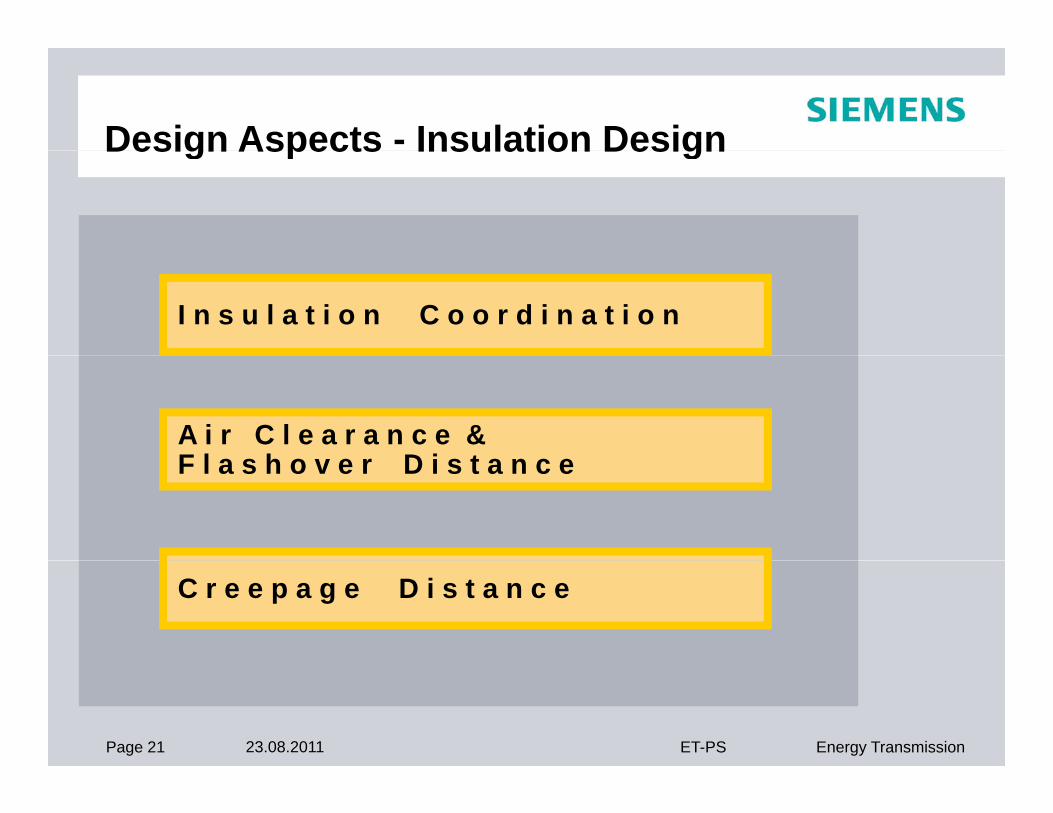
Design Aspects - Insulation DesignDesign Aspects Insulation Design
I n s u l a t i o n C o o r d i n a t i o n
A i r C l e a r a n c e &F l h D i tF l a s h o v e r D i s t a n c e
C r e e p a g e D i s t a n c e
Page 21 23.08.2011 ET-PS Energy Transmission
Design Aspects- Insulation DesignDesign Aspects Insulation Design
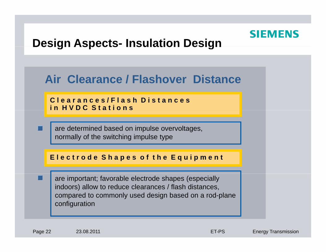
Air Clearance / Flashover DistanceAir Clearance / Flashover Distance C l e a r a n c e s / F l a s h D i s t a n c e s i n H V D C S t a t i o n s
are determined based on impulse overvoltages,normally of the switching impulse type
E l e c t r o d e S h a p e s o f t h e E q u i p m e n t
are important; favorable electrode shapes (especially indoors) allow to reduce clearances / flash distances, compared to commonly used design based on a rod-planeconfiguration
Page 22 23.08.2011 ET-PS Energy Transmission
configuration
Design Aspects - Insulation DesignDesign Aspects Insulation Design
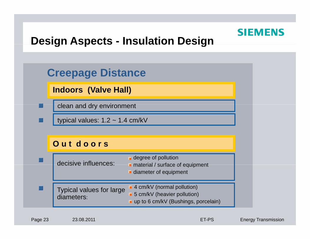
Creepage DistanceCreepage Distance Indoors (Valve Hall)
l d d i tclean and dry environment
typical values: 1.2 ~ 1.4 cm/kV
O u t d o o r s
decisive influences:degree of pollutionmaterial / surface of equipmentdecisive influences:
Typical values for largedi t
material / surface of equipmentdiameter of equipment
4 cm/kV (normal pollution) 5 cm/kV (heavier pollution)
Page 23 23.08.2011 ET-PS Energy Transmission
diameters: 5 cm/kV (heavier pollution)up to 6 cm/kV (Bushings, porcelain)
Insulation Co-ordination with ZnO-ArrestersArresters
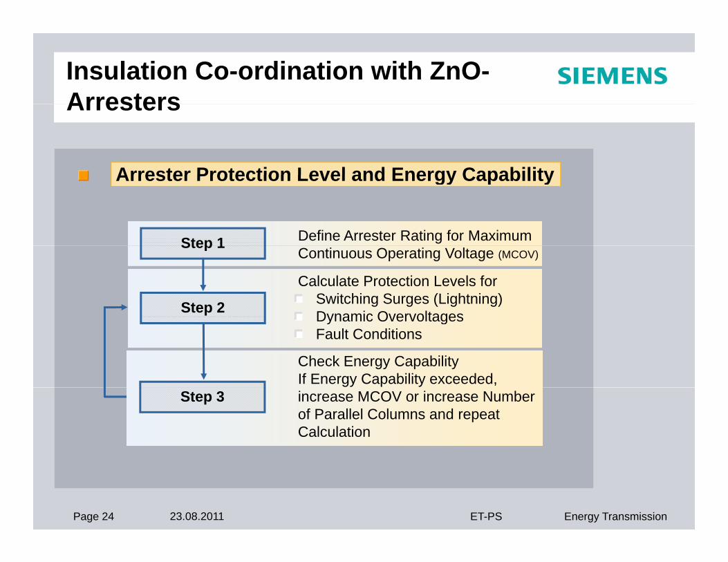
Arrester Protection Level and Energy CapabilityArrester Protection Level and Energy Capability
Step 1 Define Arrester Rating for Maximum
Step 2
Calculate Protection Levels forSwitching Surges (Lightning)Dynamic Overvoltages
Step 1Continuous Operating Voltage (MCOV)
Check Energy CapabilityIf Energy Capability exceeded,
Dynamic Overvoltages Fault Conditions
Step 3 increase MCOV or increase Number of Parallel Columns and repeat Calculation
Page 24 23.08.2011 ET-PS Energy Transmission
Page 25 23.08.2011 ET-PS Energy Transmission
Page 26 23.08.2011 ET-PS Energy Transmission
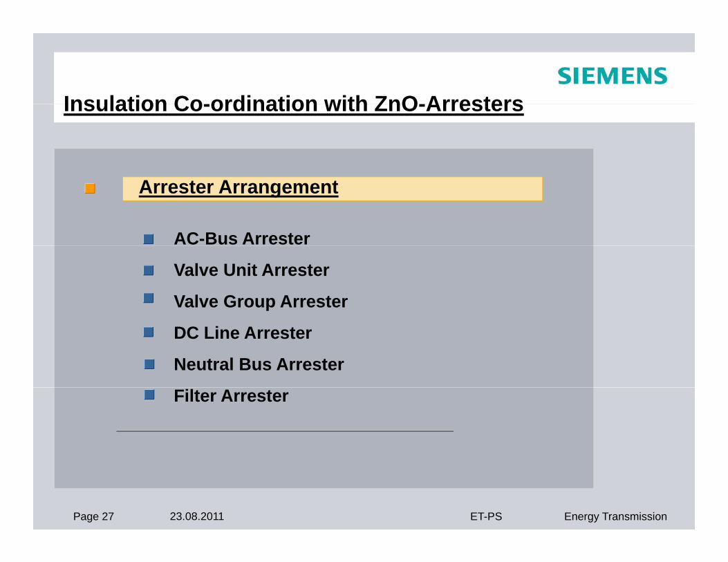
Insulation Co-ordination with ZnO-ArrestersInsulation Co-ordination with ZnO-Arresters
Arrester Arrangement
AC-Bus Arrester
Valve Unit Arrester
Valve Group Arrester
DC Line Arrester
Neutral Bus Arrester
Filter Arrester
Page 27 23.08.2011 ET-PS Energy Transmission
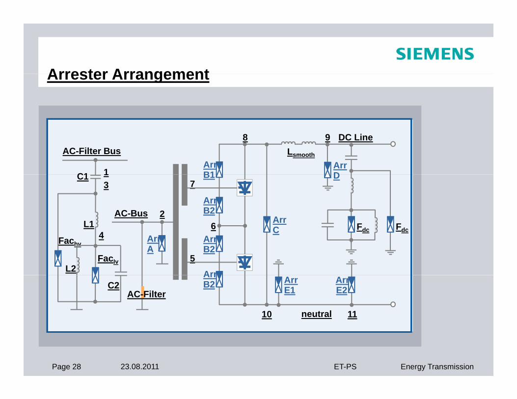
Arrester ArrangementArrester Arrangement
AC-Filter Bus
C1 1ArrB1
8 9
ArrD
Lsmooth
DC Line
C1 13
L1AC-Bus 2
B1
ArrB2
7
6 Arr
D
F FL14Fachv
L2
ArrA
ArrB2
Arr
6
5
C Fdc Fdc
FacIv
C2ArrB2
10 11
ArrE1
ArrE2
neutral
AC-Filter
Page 28 23.08.2011 ET-PS Energy Transmission

Page 29 23.08.2011 ET-PS Energy Transmission
Page 30 23.08.2011 ET-PS Energy Transmission
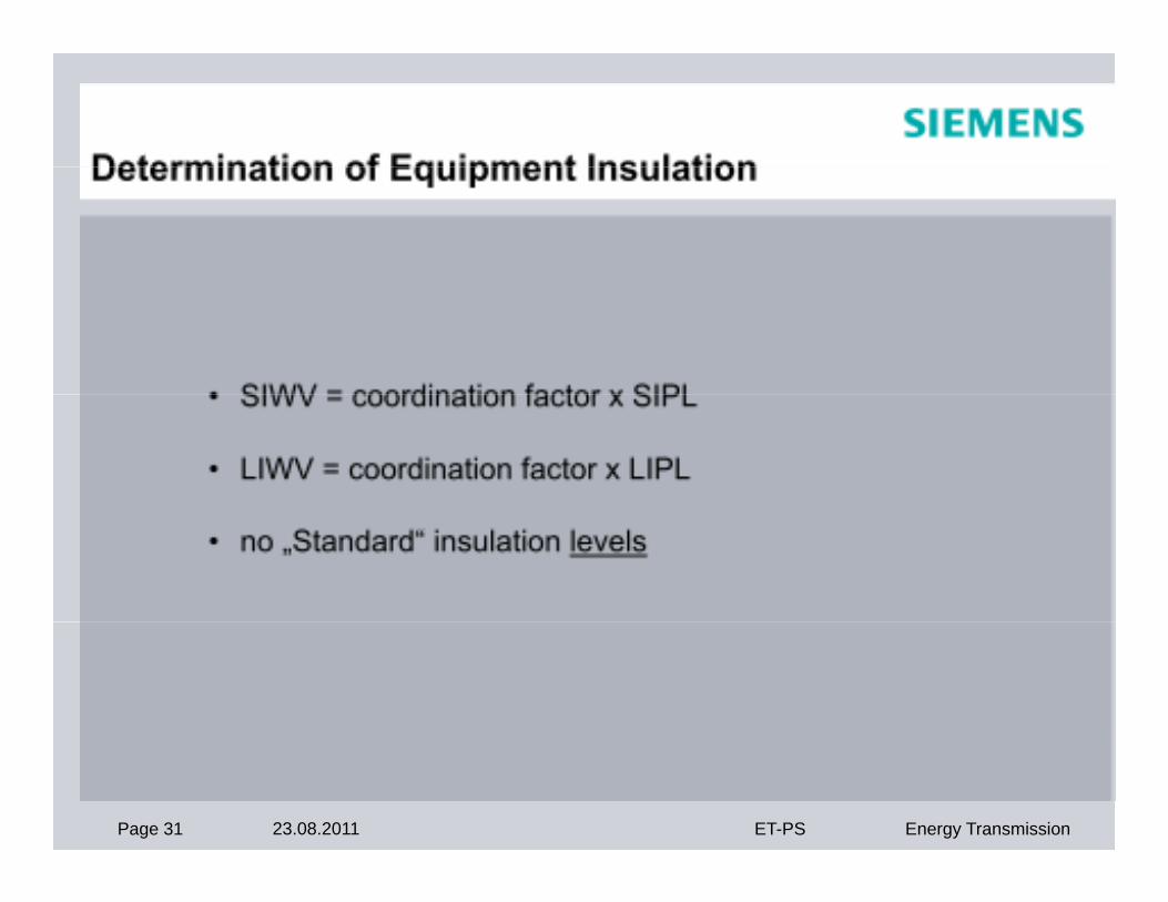
Page 31 23.08.2011 ET-PS Energy Transmission
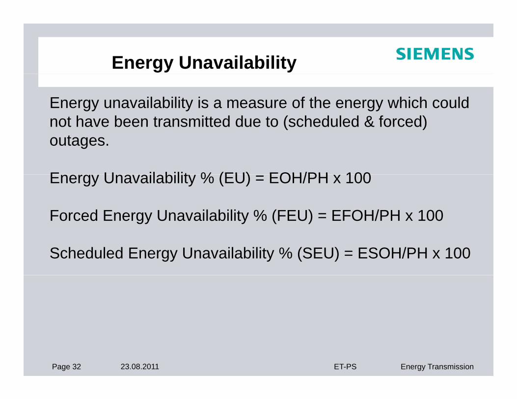
Energy Unavailability
Energy unavailability is a measure of the energy which could not have been transmitted due to (scheduled & forced)not have been transmitted due to (scheduled & forced) outages.
E U il bilit % (EU) EOH/PH 100Energy Unavailability % (EU) = EOH/PH x 100
Forced Energy Unavailability % (FEU) = EFOH/PH x 100
Scheduled Energy Unavailability % (SEU) = ESOH/PH x 100
Page 32 23.08.2011 ET-PS Energy Transmission
Energy AvailabilityEnergy Availability
A measure of the energy which could have been transmitted except for limitations of capacity due to outages, arising from any cause, either forced or scheduled.
Energy Availability % (EA) = (100 - EU)
Page 33 23.08.2011 ET-PS Energy Transmission
ReliabilityReliability
Reliability is expressed in terms of the number of forced outages of curtailment occurrences of poles and Bipole per unit of time, usually one year.
EOF is the equivalent outage frequency which shall be calculated as follows:
EOF = number of one pole outages x 1+ number of other pole outages x 1+ number of bipole outages x 2
Page 34 23.08.2011 ET-PS Energy Transmission
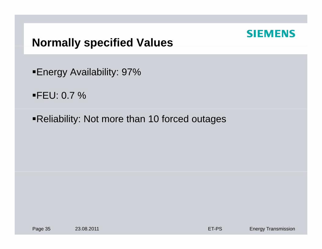
Normally specified ValuesNormally specified Values
Energy Availability: 97%
FEU: 0.7 %
Reliability: Not more than 10 forced outages
Page 35 23.08.2011 ET-PS Energy Transmission
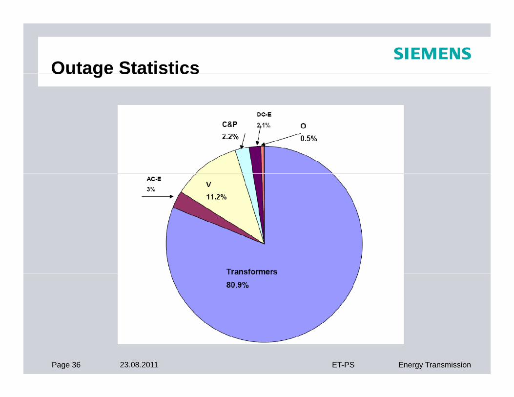
Outage StatisticsOutage Statistics
Page 36 23.08.2011 ET-PS Energy Transmission
HVDC Station Losses
Losses calculated as per IEC-61803
No load losses and load losses are guaranteed
Page 37 23.08.2011 ET-PS Energy Transmission

THANK YOU
Page 38 23.08.2011 ET-PS Energy Transmission