advantages of hvdc - usaid sari/energy integration · technical considerations bulk transmission of...
TRANSCRIPT

Advantages of HVDCg
Why HVDC rather than HVAC?
Long distances make HVDC cheaper
Improved link stabilityp y
Asynchronous link
Right of way for an AC Line designed to carry Right-of-way for an AC Line designed to carry
2,000 MW is more than 70% wider than the
i ht f f DC li f i l t itright-of-way for a DC line of equivalent capacity.
Page 1 23.08.2011 ET-PS Energy Transmission

Technical Considerations
Bulk transmission of Power at voltages upto 800kV
Technical Considerations
Back-to-back HVDC converters are used to connect two AC systems with different frequencies –two regions whereAC systems with different frequencies two regions where AC is not synchronized
S b i C bl T i iSubmarine Cable Transmission
Transmission at reduced voltage
Inherent Overload Capability
Page 2 23.08.2011 ET-PS Energy Transmission

Economical ConsiderationsEconomical Considerations
Comparison
HVDC HVAC
Terminal Cost higher lower
Comparison
Line Cost lower higher
Right-of-Way Cost lower higher
Conclusion
HVDC is more economical for transmission distances longer thanHVDC is more economical for transmission distances longer than the break-even distance
If capitalisation of losses and right-of-way cost are included in th t i th b k di t i f th d d
Page 3 23.08.2011 ET-PS Energy Transmission
the cost comparison, the break-even distance is further reduced

Example Losses on Optimized Systems for 1200 MWSystems for 1200 MW
Page 4 23.08.2011 ET-PS Energy Transmission

Economical ConsiderationsEconomical Considerations
C it li d L / B k E Di tCapitalised Losses / Break-Even-Distance
total AC cost
costs
break-eveneven-
distance
DC lossesAC l
total DC cost
DC line
losses
DC terminals
t i iAC terminals
AC line
Page 5 23.08.2011 ET-PS Energy Transmission
transmission distance
AC terminals

Economical ConsiderationsEconomical Considerations
Right-of-WayRight-of-Way
Typical Transmission Line Structures for approx. 2000 MW
± 500 kV DC60m
2 x 500 kV AC110 m
Page 6 23.08.2011 ET-PS Energy Transmission
± 500 kV DC 2 x 500 kV AC

Comparision of Losses-Case StudyComparision of Losses Case Study
Parameter HVDC System AC System
Voltage ±500 kV 400kV (1D/C+1S/C)
Power 2250 MW 2250 MW
Line Configuration Quad Bersimis Quad Moose
Line Length 970 km 970 km
Losses 135 MW (inc terminal 216 MWlosses)
Capitalisation of diff with 97% Availability and 60%
tili ti ) t iff @10
USD 41 million
Page 7 23.08.2011 ET-PS Energy Transmission
utilisation); tariff @10 cents

Technical ConsiderationsTechnical Considerations
Typical HVDC Short-Time Overload Characteristics
1,6
O l d
1,4
1,5
Overloadin pu
20°C ambient temperature
1,2
1,3
40°C ambient temperature
1
1,1
Page 8 23.08.2011 ET-PS Energy Transmission
0,01 0,1 1 10 100 1000minutes

Technical ConsiderationsTechnical Considerations
Inherent Continuous HVDC Overload vs. Ambient Temperature
1,4Overload
1,3
with redundant cooling
in pu
1,2
g
without redundant cooling
1
1,1
Ambient Temperature in Degree Celsius
Page 9 23.08.2011 ET-PS Energy Transmission
-5 0 15105 20 25 30 35 40

HVDC Long Distance Transmission Systems
Monopolar
Systems
Transmission Line
p
Terminal A Terminal B
Bipolar
Pole 1
Transmission LineTerminal A Terminal B
Pole 2
Page 10 23.08.2011 ET-PS Energy Transmission
Line

HVDC Cable Transmission SystemsHVDC Cable Transmission Systems
HVDC Classic Bipole
Pole 1
Pole 2
Transmission CableTerminal A Terminal B
P l 1
HVDC PLUS Symmetrical Monopole
Cable Systems
Transmission Terminal A Terminal B
Pole 1
Pole 2 Submarine Cable Systems Land Cable Systems
Cable Systems
Page 11 23.08.2011 ET-PS Energy Transmission
CableTerminal A Terminal B

HVDC Back-to-Back Links
Back-to-Back Technical Reasons
HVDC Back to Back Links
Different System Frequencies (f1 f2)
Different System Controls ACACACAC y(f1 f2)
Exchange of low Power compared to the Size of the interconnected AC Systems
P ti f di Di t b
System A System B
ACACACAC
Prevention of cascading Disturbances (“Firewall”)
Page 12 23.08.2011 ET-PS Energy Transmission

HVDC Long Distance Transmission SystemsMulti Terminal
Terminals in Parallel
Terminals in Series
Page 13 23.08.2011 ET-PS Energy Transmission

FUNDAMENTAL OF HVDC OPERATION
∆h
water
water
1 Ohm10 V 9.0 V
1 A
13 Ohm800 kV 775.6 kV
1875 A
Page 14 23.08.2011 ET-PS Energy Transmission

Basic HVDC Single Line Diagram
DC OH Line
DC Filter:DT 12/24
ThyristorValves
Smoothing Reactor
DC Filter:DT 12/24
ThyristorValves
Smoothing Reactor
Converter Transformer
DT 12/24DT 12/36
Converter Transformer
DT 12/24DT 12/36
DC Filter:DT 12/24DT 12/36
400 kV
DC Filter:DT 12/24DT 12/36
400 kV AC Bus
AC Filters,Reactors
AC Bus
AC Filters
Page 15 23.08.2011 ET-PS Energy Transmission

BipolarModes of Operation
Bipolar
DC OH Line
ThyristorValves
Smoothing Reactor
ThyristorValves
Smoothing Reactor
Current
Converter Transformer
Converter Transformer
Current
400 kV 400 kV
Current
AC Bus
AC Filters,Reactors
AC Bus
AC Filters
Page 16 23.08.2011 ET-PS Energy Transmission

Monopolar Metallic ReturnModes of Operation
Monopolar Metallic Return
DC OH LineSmoothing Reactor Smoothing Reactor
ThyristorValves
g
ThyristorValves
g
Current
Converter Transformer
Converter Transformer
C t
400 kV AC Bus
400 kV AC Bus
Current
AC Filters,Reactors
AC Filters
Page 17 23.08.2011 ET-PS Energy Transmission

Monopolar Metallic ReturnModes of Operation
DC OH LineSmoothing Reactor Smoothing Reactor
Monopolar Metallic Return
ThyristorValves
g
ThyristorValves
g
Current
Converter Transformer
Converter Transformer
400 kV AC Bus
400 kV AC Bus
Current
AC Filters,Reactors
AC Filters
Page 18 23.08.2011 ET-PS Energy Transmission

Monopolar Ground ReturnModes of Operation
Monopolar Ground Return
DC OH Line
ThyristorValves
Smoothing Reactor
ThyristorValves
Smoothing Reactor
Current
Converter Transformer
Converter Transformer
Current
400 kV 400 kV AC Bus
AC Filters,Reactors
AC Bus
AC Filters
Page 19 23.08.2011 ET-PS Energy Transmission

Overall Layout of HVDC stationOverall Layout of HVDC station
Page 20 23.08.2011 ET-PS Energy Transmission

Converter Island
Page 21 23.08.2011 ET-PS Energy Transmission

Isometric view – Conventional Bipolar HVDCHVDC
Page 22 23.08.2011 ET-PS Energy Transmission

Example HVDC “Classic”Example HVDC Classic
Page 23 23.08.2011 ET-PS Energy Transmission

Key Components of HVDCBipolar HVDC TerminalBipolar HVDC Terminal
System A System B
ACACACAC
1. AC Switchyard
2. AC Filters
To/ fromotherterminal
Controls, Protection, Monitoring
3. Transformers
4. Converter Valves
Pole 1
Pole 2
ACfilter
DCfilter
DC5. Smoothing Reactors
and DC Filters
6. DC Switchyard
Pole 2
2211 33 44 55
DCfilter
66
Page 24 23.08.2011 ET-PS Energy Transmission

HVDC Terminal RequirementsHVDC Terminal Requirements
AC Switchyard Connects the Terminal to the AC System
AC Filters Capacitor BanksAC Filters, Capacitor Banks Reactive Power SupplyFilter harmonic Currents
Converter Transformers Obtain the AC Voltage needed for the required DC VoltageObtain 12-Pulse Operation (Star and Delta Connection)Allow for Series Connection of 6-Pulse Bridges
Page 25 23.08.2011 ET-PS Energy Transmission

HVDC Terminal RequirementsHVDC Terminal Requirements
Thyristor Valves Convert AC to DC and vice-versaConnect 6-Pulse Bridges in Series for required DC Voltage
Smoothing Reactors and DC Filters Smoothen the DC CurrentA id R ith DC LiAvoid Resonance with DC LineLimit Interference caused by DC Side Harmonics
DC Switchyard Achieve required DC Side Transmission Configuration
Page 26 23.08.2011 ET-PS Energy Transmission

Main EquipmentsMain Equipments
Thyristor ValvesyValve CoolingConverter TransformerSmoothing ReactorDC SwitchesAC FiltersDC FiltersPLC FilterGround Electrode
Page 27 23.08.2011 ET-PS Energy Transmission

Thyristor ValvesThyristor Valves
The rectification and inversion process is carried out by theThe rectification and inversion process is carried out by the
thyristor valves
Housed inside the valve halls
Page 28 23.08.2011 ET-PS Energy Transmission

Thyristors
Thyristor Technology with direct Light-T i d Th i t
Thyristors
Triggered Thyristors Rated Voltage up to 800 kV Rated Current more than 3,000 A Free from Oil and exclusive Use of
Flame-retardant self-extinguishing Materials Reduced Fire-Hazard
Efficient and Corrosion-free Water Efficient and Corrosion free Water Cooling
Excellent Seismic Performance
Thyristor
Page 29 23.08.2011 ET-PS Energy Transmission

Direct Light Triggered Thyristor LTTDirect Light Triggered Thyristor LTT
80 % less Electronic Components Di t L Li ht t i d Th i t
High Reliability
Direct Laser Light-triggered Thyristor
Thyristor Blocking Voltage: 8 kV Thyristor Wafers:
4" for currents up to 2,200 A 5" for currents up to 3,700 A
Page 30 23.08.2011 ET-PS Energy Transmission

Comparison of Electrical with Direct Light TriggeringLight Triggering
E T T E T T Triggering and Monitoring Functions
L T TL T TFiring and Monitoring System conveniently from the Ground to Thyristor Potential
voltage detection
Functions from the Ground to Thyristor Potential
voltage detection
check-backauxiliary powerlogicelectric gate pulseprotective gate pulse
voltage detection
electrical gate pulse
protective gate pulse
optical trigger signal
check-back signal
check-back signal
optical gatepulse
Valve Base Electronics withlow power LED
signalsignal
Valve Base Electronic withhigh power laser
signal pulse
Page 31 23.08.2011 ET-PS Energy Transmission
low power LEDETT
high power laserLTT

Parallel Water CoolingParallel Water Cooling
The Siemens Design of the Valve-Cooling Circuit with Parallel-Water Cooling
It provides all thyristors with the same cooling water temperature
has been in Operation for more than 30 Years
same cooling water temperature Electrolytic currents are minimized
by the use of grading electrodes C f l h i f t i l ll Careful choice of materials allows
operation without de-oxygenizing equipment
None of these systems had None of these systems had corrosion problems
a Thyristorb Heat Sink
Page 32 23.08.2011 ET-PS Energy Transmission
b Heat Sinkc Pipingd Manifold

Page 33 23.08.2011 ET-PS Energy Transmission

Thyristor Valves-PEB BuildingThyristor Valves PEB Building
Page 34 23.08.2011 ET-PS Energy Transmission

Valve hall
Page 35 23.08.2011 ET-PS Energy Transmission

Valve hall
Page 36 23.08.2011 ET-PS Energy Transmission

Thyristors Valves - Module LayoutThyristors Valves Module Layout
Page 37 23.08.2011 ET-PS Energy Transmission

Simplified Cooling Circuitp gM
C/AEXP
OUT DOOR IN DOOR
Page 38 23.08.2011 ET-PS Energy Transmission

Air Blast Cooler
FLUID IN
FLUID OUT
Page 39 23.08.2011 ET-PS Energy Transmission T3767

Valve Hall-External View
Page 40 23.08.2011 ET-PS Energy Transmission

East-South Interconnector II, India, 20032003
Page 41 23.08.2011 ET-PS Energy Transmission

Converter TransformerConverter Transformer
Provide the AC voltage for the converter
Subject to DC voltage and currents on the Valve side.
Can be two winding or three winding depending on MVA rating and size
Subject to special tests such as DC withstand, polarity reversal and heat run test with harmonic currents taken into account
Page 42 23.08.2011 ET-PS Energy Transmission

Winding ArrangementWinding Arrangement
Core R-Regulating Wdg
L Li WdL- Line Wdg
V-Valve Wdg
R L V
Page 43 23.08.2011 ET-PS Energy Transmission

Winding arrangement
Core R-Regulating Wdg
L Li WdL- Line Wdg
V-Valve Wdg
V L R
Page 44 23.08.2011 ET-PS Energy Transmission

Converter Transformer
Page 45 23.08.2011 ET-PS Energy Transmission

Converter Transformer
Page 46 23.08.2011 ET-PS Energy Transmission

Converter Transformers
Page 47 23.08.2011 ET-PS Energy Transmission
400 MVA 1-ph / 3-w 354 MVA 1-ph / 3-w

Smoothing ReactorgRemoves ripples from DC voltage
Limits rate of rise of current in case of DC line faults
Limits higher order harmonics in DC line
Limits possible resonance at fundamental and 2nd harmonicLimits possible resonance at fundamental and 2 harmonic frequencies
Page 48 23.08.2011 ET-PS Energy Transmission

HVDC Smoothing Reactor
Ai C D i
HVDC Smoothing Reactor
Oil i d D i Air-Core DesignOil immersed Design
150 H150 mH
500 kV DC
1,800 A
270 mH
500 kV DC
3 000 A
Page 49 23.08.2011 ET-PS Energy Transmission
3,000 A

Smoothing Reactorg
Inductance 250 mH (two coils @125 mH)Rated voltage 500 kV dcRated current 2000 A dc
Page 50 23.08.2011 ET-PS Energy Transmission

Siemens HVDC TransmissionSupplies in IndiaSupplies in India
Converter Transformer and Valve Hall –Talcher Station (ESI - II) AC Harmonic Filters – Talcher Station (ESI - II)Talcher Station (ESI - II)
Page 51 23.08.2011 ET-PS Energy Transmission

High Speed DC SwitchesHigh Speed DC Switches
Switches to commutate direct current(MRTB, MRS, HSNBS, HSGS)
Metallic Return Transfer Breaker (MRTB)d M t lli R t S it h (MRS)and Metallic Return Switch (MRS)
Use of standard SF6 circuit breakers
Page 52 23.08.2011 ET-PS Energy Transmission

MRTB & GRTS
Page 53 23.08.2011 ET-PS Energy Transmission

MRTB & GRTS
Page 54 23.08.2011 ET-PS Energy Transmission

MRTB & GRTS
Page 55 23.08.2011 ET-PS Energy Transmission

Operation of MRTBp
Page 56 23.08.2011 ET-PS Energy Transmission

Bipolar and Monopolar metallic return is th l d f O ti
Why and when Ground Return ?
the normal mode of Operation
Permanent fault on one Pole conductors of DC line.Scheduled maintenance for major work of DC line
Page 57 23.08.2011 ET-PS Energy Transmission
Scheduled maintenance for major work of DC line.

TYPICAL LAYOUT OF ELECTRODE STATION
Page 58 23.08.2011 ET-PS Energy Transmission

Ground Electrodes EffectsGround Electrodes Effects
Local Effects( Upto < 1 km)
Safety of Humans and Animals
High temperature rise of Ground and drying of soil.High temperature rise of Ground and drying of soil.
Remote Effects (may be upto 50 Km and beyond)
Potential rise can cause DC current flow in transformerNeutrals
Corrosion of buried metallic objects.
Page 59 23.08.2011 ET-PS Energy Transmission

Design RequirementsLocal Electrode parameters.
Ground Electrode resistance ≤ 0.3 Ω
Touch Voltage ≤ 40 Volts
St V lt ≤ 6 V lt Step Voltage ≤ 6 Volts
Current Density ≤ 0.5 A/m2
Temperature on the surface of sub-electrode: ≤ 100 ˚ C.
Remote Effects.
The Ground potential rise and electric field shall decay fast and shall be negligible (few Volts) within 15-20 kms of electrode site.
Page 60 23.08.2011 ET-PS Energy Transmission
electrode site.
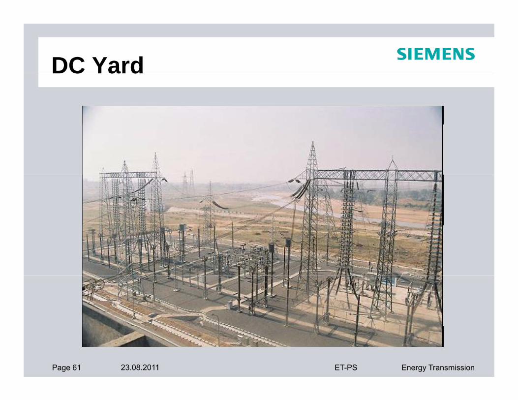
DC Yard
Page 61 23.08.2011 ET-PS Energy Transmission

DC Yard
Page 62 23.08.2011 ET-PS Energy Transmission

Auxiliary Systems-HVDCAuxiliary Systems HVDC
• Auxiliary Power
• LT Power System
• DG Set
• DC Power/UPS
• Air Conditioning/Ventilation
• Fire Fighting/Detection
• IlluminationIllumination
• PA System
• Valve Cooling System
• Oil Filtration System• Oil Filtration System
• Service Water
• Telephone & PA System
Page 63 23.08.2011 ET-PS Energy Transmission

Auxiliary Power SourcesAuxiliary Power Sources
Usually two 33kV/11kV sources
DG Set connected on LT busDG Set connected on LT bus
Voltage Variation: ±10%
Frequency Variation: ±5%
Page 64 23.08.2011 ET-PS Energy Transmission

Typical Aux Power Scheme for HVDC StationHVDC Station
Page 65 23.08.2011 ET-PS Energy Transmission

Valve Hall Ventilation Requirements
Inside DB temperature 50ºC±2ºC
Inside R.H. 43% ±5%
Clean room to ISO class 7 as per ISO 14644-1:1999Clean room to ISO class 7 as per ISO 14644 1:1999
Positive pressure – 3mm of water column
Dedicated one running and one standby AHU Dedicated one running and one standby AHU
Supply air through high efficiency filters to main desired
clean room condition
Page 66 23.08.2011 ET-PS Energy Transmission

Fire Protection - StagesFire Protection Stages
F i r e P r o t e c t i o n
Fire Prevention
Fire Detection
Fire Fighting
Smoke Evacuation
Fire Fighting
Page 67 23.08.2011 ET-PS Energy Transmission

Fire Protection - Design AspectsFire Protection Design Aspects
F i r e P r e v e n t i o n
Separated areas
design of equipment
maintenance
Page 68 23.08.2011 ET-PS Energy Transmission

Fire Protection - Choice of MaterialFire Protection Choice of Material
Fire Protection Walls
Dry Composite TransformerWall BushingWall Bushing
Minimised Inflammable Materials
Dry Composite Wall BushingDry Composite Wall Bushing
Page 69 23.08.2011 ET-PS Energy Transmission

Fire Protection - DetectionFire Protection Detection
F i r e D e t e c t i o n
valve hall
transformers
control / service building
indication / control system
g
Page 70 23.08.2011 ET-PS Energy Transmission

Fire Protection - TransformersFire Protection Transformers
BHBHBHBuchholz RelaysBH
VESDA Detectors
Air Sampling Tubes
V
Ultra Violet Detectors
Infra Red Sensors
V V V
Page 71 23.08.2011 ET-PS Energy Transmission
V V V

Fire Protection - Control RoomsFire Protection Control Rooms
Optical Smoke Detectors
Control Room
Ionisation Smoke Detectors
Fire Protection WallsControl Room
Office CO2 Fire FightingCO2
MeetingRoom
Lavatory
Page 72 23.08.2011 ET-PS Energy Transmission

Fire FightingFire Fighting
Technology and Installations
deluge system
carbondioxide (CO2)
hydrants
portable fire extinguishers
Page 73 23.08.2011 ET-PS Energy Transmission

Fire Protection - Deluge SystemFire Protection Deluge System
Deluge System
Selective Initiator of Transformerand Valve fire fighting
Deluge System
Hydrant System (if required)
Page 74 23.08.2011 ET-PS Energy Transmission