a new method to test masonry shear characteristics thought
TRANSCRIPT
19th
World Conference on Non-Destructive Testing 2016
1 License: http://creativecommons.org/licenses/by/3.0/
A New Method to Test Masonry Shear Characteristics
Thought Flat Jack (FJ-SCT Method)
Dario FOPPOLI 1, Anselmo PULCINI
1
1 Foppoli Moretta e Associati srl, Tirano (SO), Italy
Contact e-mail: [email protected]
Abstract. The evaluation of the seismic behaviour of existing buildings is a problem
increasingly felt in Italy, with reference principally to the many earthquakes recently
occurred. For the historical buildings this behaviour is strongly related to the shear
strength and stiffness of masonry walls. The test methods currently available to
determine the shear behaviour of the walls require the application of load through
the use of cylindrical jacks and generally they have a character of high
destructiveness. So these methods are not practically applicable to existing
buildings, if they have an heritage value and if they are not previously badly
damaged.
It has been developed by the authors a new testing technique based on the use
of flat jacks that, belonging to the category of slightly destructive test methods,
allows to greatly reduce the impact of the tests on the buildings and then to apply
them to a wide range of cases. In order to test this new technique (FJ-SCT method)
they were built in laboratory a series of brick panels similar for texture, composition
and characteristics to the walls of the historical Italian buildings. First of all both the
materials and the panels were subjected to standardized tests in order to define their
mechanical characteristics. It was then built a special testing frame so as to
reproduce the on site operating conditions in order to allow the laboratory
calibration of the test technique. The results of the laboratory tests carried out by
traditional methods were then compared with the results of the laboratory tests
carried out by the FJ-SCT method experiencing a good correspondence of results. In
order to assess the actual on site applicability of the technique, FJ-SCT method was
finally applied during on site tests on panels made of brick masonry or stone
masonry (also very common in the historical buildings in northern Italy) obtaining
positive results relating to efficiency and effectiveness of the test procedure.
Introduction
Mechanical parameters that characterize the shear behaviour of walls are essential to carry
out a proper assessment of the structural safety both in the seismic and in the static field. If
we consider the seismic field, we can see that among the twenty-eight failure mechanisms
listed by the Italian guidelines [1] that allow you to carry out the preliminary assessment of
structural safety of "churches ... and other structures with large halls without intermediate
horizontal elements” (the so called level LV1 assessment), eight mechanisms directly
involve the shear strength of the masonry. Also in static field [3] several damage
mechanisms, especially those that are related to differential settlement of foundations, are
determined by the shear behaviour of masonry.
More info about this article: http://ndt.net/?id=19243
2
Despite the extreme importance of this, structural codes are rather lacking when they come
to dealing with the experimental methods useful for assessing the relevant structural
quantities. In the sector of laboratory tests, two methods are standardized:
• tests on triplets of bricks;
• diagonal compression tests.
The test on triplets [4] is aimed only at determining the shear strength of mortar joints;
however, this mechanism is rarely activated in damage detected on masonry, both in the
static and in the seismic field. The diagonal compression test [5] allows, instead, the
determination of the shear strength in masonry assemblages.
As far as in situ tests are concerned, literature provides feedback of the application of
methodologies derived from the previous ones. Principally the tests currently applied can
be classified according to three methodologies:
• shove tests of single brick;
• diagonal compression tests;
• shear compression tests.
On site shove tests [6], which are derived from laboratory triplets tests [4], are only
applicable to brick masonry and assume that the back joint of the brick, which is not
removed, has no significant effect on the results (hypothesis that, in the opinion of the
authors, is arbitrary because this kind of test involves large displacements). This test is
classified as slightly destructive, but also provides only the value of the shear strength of
mortar joints, not exhaustive of the global behaviour of the masonry. The diagonal
compression test is carried out on site with procedures derived from the standard [5];
typically, the diagonal load is applied through the use of cylindrical jacks [7]. To locate
these jacks and elements of contrast major demolition works are required: this means that
these are Highly Destructive Tests, so as to be impractical in use for analysis of existing
buildings if they are not already badly damaged. The shear compression test, which, from a
theoretical point of view, is the one that best describes the actual behaviour of the walls [7],
is typically performed by inserting a contrast frame made with steel beams in the masonry
and by applying the load both vertically and horizontally through cylindrical jacks. For this
reason, this method requires the execution of relevant demolition works too and, if possible,
is even more destructive than the previous one, therefore still less applicable in practice.
Incidentally, it is helpful to observe, beyond the obvious considerations of conservation,
that the making of the cuts and demolition required for the execution of the diagonal
compression or shear compression tests transmits significant vibrations to the masonry, that
is already a flimsy material, and also causes a kind of "decompression" of the panel:
therefore there are significant doubts that the thus prepared panels maintain the same
structural characteristics of the original masonry.
Because of the difficulty in experimentally determining the relevant quantities, the method
usually applied calculates the shear strength of the masonry in an indirect way, for example
by applying the well-known, standardized and reliable flat jacks test [9], which provides the
mechanical masonry properties (in compression). The shear characteristics are then
calculated interpolating the values taken form the standard tables, for example those
contained in the Italian code [2]. In the hypothesis of elastic, homogeneous and isotropic
material, there is the well-known relationship that correlates E, ν (both determined through
flat jacks tests) and G, but it has, however, be remembered that the actual conditions of the
material are very different, and also that there is no reliable correlation between the
compressive and the shear strength.
Finally it is useful to observe that the Italian guidelines [1] specifically states that "Non
Destructive diagnostic Techniques of indirect type, such as sonic ultrasonic tests, assess the
homogeneity of the mechanical parameters in different parts of the building, but they do not
provide a reliable quantitative estimation of their values, since they are derived from the
3
measurement of matchless parameters (for example, the velocity of propagation of pulses).
Therefore, the direct measurement of the mechanical parameters of the masonry, in
particular those relating to resistance, can be performed only through Slightly Destructive
or Destructive Tests, even if applied to limited portions. Calibrations of Non Destructive
Tests with Destructive Tests can be used to reduce the invasiveness of the investigation
campaign." This confirms the need to have reliable test methods for the direct
determination of masonry shear strength and stiffness.
The careful examination of the various methodologies used on site and described above
made it possible to define that the most interesting configuration is related to shear
compression tests as already applied on site by Sheppard [8]. A new on site shear test
technique based on the use of flat jacks, named "Flat Jacks for Shear Compression Test"
(FJ-SCT method), was then set up by the authors. This method has to be classified in the
category of only Slightly Destructive Tests (SDT), it reduces the impact of the tests on the
buildings and then it is actually applicable to a wide range of cases. This technique has
been tested in laboratory on brick masonry panels that, for texture, composition and
resistance, are equal to the characteristics of the walls of the historic buildings of northern
Italy. It has also been applied to the site, on buildings damaged by the earthquake of 2012
in Emilia, to get feedback on the efficiency and effectiveness of the developed procedures.
1. Shear compression test
1.1 Description of the testing technique
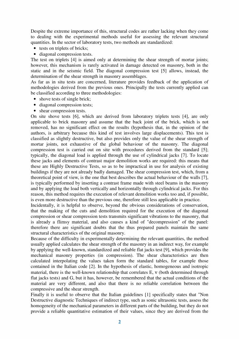
Fig. 1. Lay-out of shear compression test (FJ-SCT)
The FJ-SCT test consists in making two cuts crossing the masonry under analysis, 160-200
cm in length and 8-10 mm in thickness, placed at mutual distance b = 60-80 cm. At half
height of one of the two cuts, a flat jack, arranged vertically, is inserted and the opposite cut
is instrumented by means of displacement gauges suitable to measure horizontal
movements. In this way, the test lay-out identifies two half-panels, almost squared in shape
and b x b in size, placed one above the other, which are subjected simultaneously to shear
stress (Fig. 1). Through a vertically arranged jack, a horizontal load is applied to the panel;
the pressure is then increased until the diagonal cracking of at least one of the two half-
panels is obtained. The development of diagonal cracks confirms the correctness of the
shear failure mechanism activated within the masonry. All the tests carried out have shown
4
that with the proposed test lay-out, a horizontal displacement of 8-10 mm is sufficient to
develop diagonal cracks in the brickwork
1.2 Description of calibration campaign
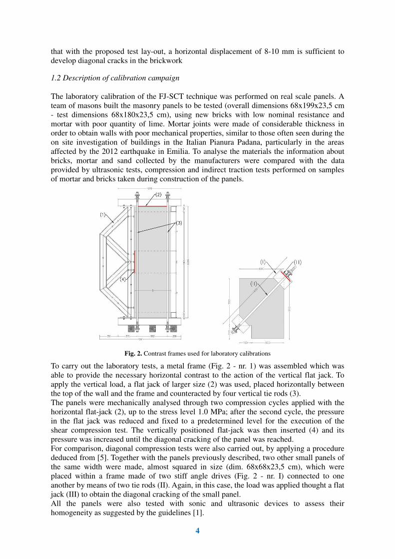
The laboratory calibration of the FJ-SCT technique was performed on real scale panels. A
team of masons built the masonry panels to be tested (overall dimensions 68x199x23,5 cm
- test dimensions 68x180x23,5 cm), using new bricks with low nominal resistance and
mortar with poor quantity of lime. Mortar joints were made of considerable thickness in
order to obtain walls with poor mechanical properties, similar to those often seen during the
on site investigation of buildings in the Italian Pianura Padana, particularly in the areas
affected by the 2012 earthquake in Emilia. To analyse the materials the information about
bricks, mortar and sand collected by the manufacturers were compared with the data
provided by ultrasonic tests, compression and indirect traction tests performed on samples
of mortar and bricks taken during construction of the panels.
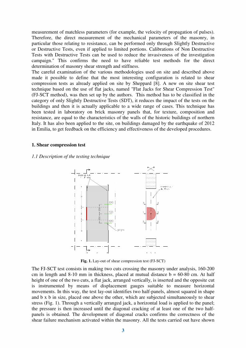
Fig. 2. Contrast frames used for laboratory calibrations
To carry out the laboratory tests, a metal frame (Fig. 2 - nr. 1) was assembled which was
able to provide the necessary horizontal contrast to the action of the vertical flat jack. To
apply the vertical load, a flat jack of larger size (2) was used, placed horizontally between
the top of the wall and the frame and counteracted by four vertical tie rods (3).
The panels were mechanically analysed through two compression cycles applied with the
horizontal flat-jack (2), up to the stress level 1.0 MPa; after the second cycle, the pressure
in the flat jack was reduced and fixed to a predetermined level for the execution of the
shear compression test. The vertically positioned flat-jack was then inserted (4) and its
pressure was increased until the diagonal cracking of the panel was reached.
For comparison, diagonal compression tests were also carried out, by applying a procedure
deduced from [5]. Together with the panels previously described, two other small panels of
the same width were made, almost squared in size (dim. 68x68x23,5 cm), which were
placed within a frame made of two stiff angle drives (Fig. 2 - nr. I) connected to one
another by means of two tie rods (II). Again, in this case, the load was applied thought a flat
jack (III) to obtain the diagonal cracking of the small panel.
All the panels were also tested with sonic and ultrasonic devices to assess their
homogeneity as suggested by the guidelines [1].
5
2. Laboratory calibrations
2.1 Building of the panels
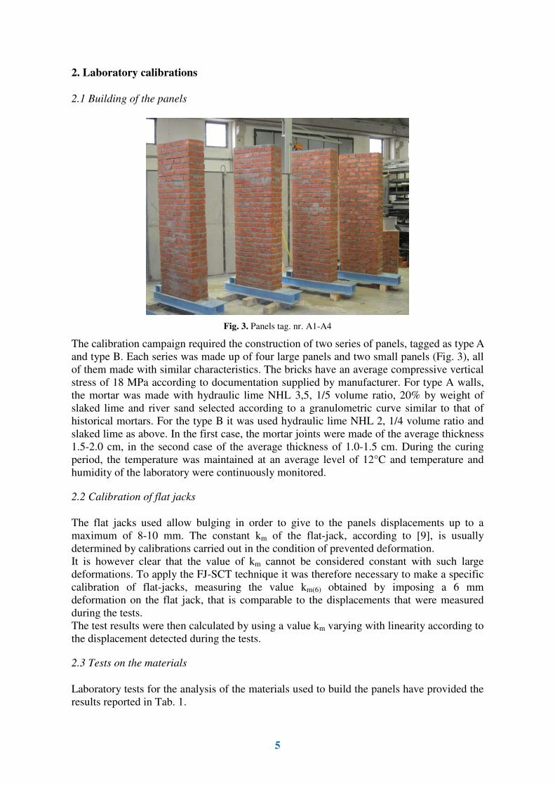
Fig. 3. Panels tag. nr. A1-A4
The calibration campaign required the construction of two series of panels, tagged as type A
and type B. Each series was made up of four large panels and two small panels (Fig. 3), all
of them made with similar characteristics. The bricks have an average compressive vertical
stress of 18 MPa according to documentation supplied by manufacturer. For type A walls,
the mortar was made with hydraulic lime NHL 3,5, 1/5 volume ratio, 20% by weight of
slaked lime and river sand selected according to a granulometric curve similar to that of
historical mortars. For the type B it was used hydraulic lime NHL 2, 1/4 volume ratio and
slaked lime as above. In the first case, the mortar joints were made of the average thickness
1.5-2.0 cm, in the second case of the average thickness of 1.0-1.5 cm. During the curing
period, the temperature was maintained at an average level of 12°C and temperature and
humidity of the laboratory were continuously monitored.
2.2 Calibration of flat jacks
The flat jacks used allow bulging in order to give to the panels displacements up to a
maximum of 8-10 mm. The constant km of the flat-jack, according to [9], is usually
determined by calibrations carried out in the condition of prevented deformation.
It is however clear that the value of km cannot be considered constant with such large
deformations. To apply the FJ-SCT technique it was therefore necessary to make a specific
calibration of flat-jacks, measuring the value km(6) obtained by imposing a 6 mm
deformation on the flat jack, that is comparable to the displacements that were measured
during the tests.
The test results were then calculated by using a value km varying with linearity according to
the displacement detected during the tests.
2.3 Tests on the materials
Laboratory tests for the analysis of the materials used to build the panels have provided the
results reported in Tab. 1.
6
Table 1. Results of tests for the analysis of the materials used to build the panels
mortar ultrasonic
velocity [m/s]
mortar compr.
strength [MPa]
mortar tension
strength [MPa]
brick ultrasonic
velocity [m/s]
test
standard
UNI EN 12504-4:
2005
UNI EN 196-1:
2005
UNI EN 12390-6:
2010
UNI EN 12504-4:
2005
type A
mean (6)
1111 0,77 0,06 2085
type B
mean (6)
864 0,55 -- 1900
2.4 Tests on the panels
The mechanical compression characteristics (Young modulus E and Poisson's ratio ν)
experimentally determined through laboratory tests on the panels are reported on Tab. 2,
where they are matched with measurements of the ultrasonic pulse velocity.
Table 2. Results of tests for the analysis of the panels
* = calculated in the first load cycle in the range (0.4-0.8MPa)
E (0.4-0.8)*
[MPa] ν (0.4-0.8)*
[MPa]
tag. nr. 1-4 ultra-
sonic velocity [m/s]
tag. nr. 5-6 ultra-
sonic velocity [m/s]
test
standard
UNI EN 12504-4:
2005
UNI EN 12504-4:
2005
type A
mean (4)
1165 0,20 1843 1836
type B
mean (4)
1826 0,10 1734 1766
The mean values of ultrasonic pulse velocity compared between the large panels and the
small ones are similar confirming their homogeneity. It is however important to stress the
wide dispersion of the results of the mechanical properties measured for all the panels
tested.
Table 3. Results of shear tests
** = calculated in the first load cycle in the range (0 - 0.07MPa)
panel
tag. nr. A1 A2 A3 A4 A5 A6 B1 B2 B3 B4 B5 B6
applied
procedure
FJ-SCT ASTM
E519-81
FJ-SCT ASTM
E519-81
σ v
[MPa]
0,4 0,4 0,6 0,6 0 0 0,4 0,4 0,8 0,8 0 0
τ v
[MPa]
0,289 0,314 0,42 0,405 0,155 0,150 0,366 0,382 0,426 0,396 0,174 0,182
G(0-0.07)**
[MPa]
750 539 492 663 -- -- 1037 750 545 339 -- --
The next step was to subject the small panels to diagonal compression tests and the large
panels (to which a constant vertical stress was applied by means of the horizontal flat jack)
to the FJ-SCT test. The results obtained are summarized in Tab. 3. In all cases, the walls
have reached shear failure developing diagonal cracks and showing significant shifts
2.5 Analysis of results
From the theoretical point of view in the panels failure can occur according to the following
two ways:
1) sliding failure along a mortar joint;
7
2) diagonal crack failure.
In the second case, it is possible to recognise two further modes:
2a) diagonal cracks obtained simultaneously on both the superposed half-panels;
2b) diagonal cracks obtained only on one of the two half-panels.
During the tests carried out (including all the on site tests) the failure mode 1) was never
reported, during laboratory tests (Fig. 4), failure occurred only with the mode 2b), during in
situ tests failure also occurred with the mode 2a).
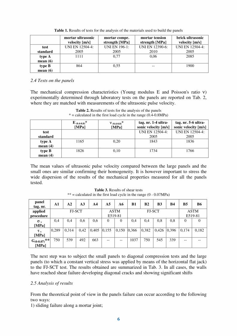
Fig. 4. Laboratory panels subjected to FJ-SCT: diagonal cracks are underlined -
shear stress vs. horizontal displacement diagram
These alternative cracking modes are indifferent for the determination of the shear strength
of the panel as it is reasonable to suppose that, up to the moment immediately before the
formation of cracks, the load is uniformly distributed in the upper and in the lower half-
panel: basically the less resistant of the two half-panels breaks first. The test method
applied is therefore equivalent to test the two half-panels simultaneously recording only the
result related to the less resistant one, so it is in favour of safety.
Laboratory tests have generally shown the previous formation of one horizontal crack in
correspondence with a mortar joint placed at the edge of the panel at half height. However,
this phenomenon, which produces no detectable effects on the measures of the transducers,
has never prevented the subsequent development of diagonal cracks that were observed
either in the upper or in the lower half-panel, not in correlation with the position of the
horizontal crack.
3 On site set up of the operating methodologies
To evaluate the actual on site applicability and effectiveness of the test, the FJ-SCT method
was applied in two heritage buildings damaged by the 2012 earthquake in Emilia: Villa La
Bertusa in Rovereto (MO) and Villa Bonasi Benucci in Stuffione (MO) [10]. In each of the
two buildings 3 tests were carried out identifying masonry panels respectively 68x176x28
cm and 60x160x28 cm in size, which were very close to the size of the panels tested in the
laboratory. The actual compressive stress was determined by flat jack tests carried out close
to the point of execution of the shear test.
8
It is useful to specify that, to perform on site test it is not necessary to remove the plaster
from the wall, unless it has a significant influence on the masonry shear strength (e.g. in the
case of cement plaster covering a thin weak wall).
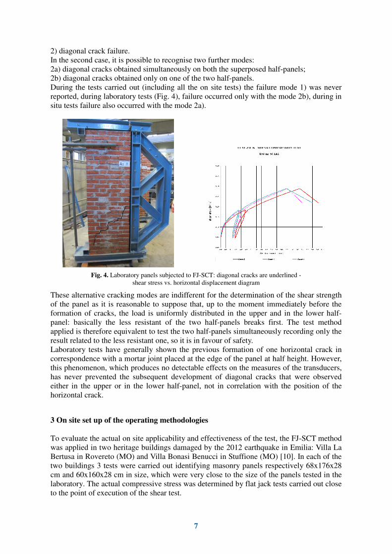
The tests have proved to be easy to apply and to provide significant results (Fig. 5). It has
to be noted incidentally that the shear strength determined is significantly higher than that
reported by the code [2]; this fact is anyway also confirmed in many documented cases [11]
and also confirmed by the standard tests carried out in the laboratory as previously
reported.
Fig. 5. In situ masonry subjected to FJ-SCT: diagonal cracks are underlined -
shear stress vs. horizontal displacement diagram
On site tests were also performed on stone masonry (rubble stone masonry or split-stone
masonry): in this case the thickness of the walls was usually larger than that previously
indicated; in some cases, for thicknesses larger than 50 cm, it was necessary to operate by
inserting two hydraulically connected flat jacks placed vertically in the slot. Again in this
case, excellent results were obtained both regarding the applicability of the testing
technique and the repeatability of the results.
4. Conclusions and recommendations
In the present paper it has been described in situ and laboratory calibration of a new testing
technique that use flat jack for assessing the shear strength and stiffness of masonry, that is
named with the acronym FJ-SCT. The developed research has shown:
• that the technique is reliable, the procedures are efficient and effective and the results
are repeatable and in line with results obtained through other test methods;
• that damage produced to the masonry by this test technique is limited and justified by
the level of the results obtained, this means that the FJ-SCT technique can be ascribed
to Slightly Destructive Test (SDTs);
However, as stated by the guidelines [1] local results have to undergo an extensive
application of non-destructive testing (NDT); in the present research these additional
measures have been taken using ultrasonic pulse velocity.
Finally it is possible to specify some recommendations highlighted by the tests carried out:
9
1) FJ-SCT produces nonetheless a limited destructiveness, so it is necessary that the test
points are accurately assessed from both the conservative and the structural point of
view, not to cause damage to the building;
2) restoration of test points is a simple but important operation and have to be done
carefully after running the test, with grouting and "cuci-scuci" techniques;
3) test results are very sensitive to the method for determining vertical stress, if it is
measured by performing a flat jack test, the test point should be chosen on the basis of
structural considerations and placed in a point with static conditions similar to the FJ-
SCT test point;
4) standard [5] contains a generic reference to "thickness of the type of wall to be tested"
without giving any information about requested thickness of the panel to be tested. The
range of validity of the laboratory calibrations performed covers for the panels a
minimum ratio width/thickness = 2.5, but the tests carried out on site confirm the
applicability of this technique even with lower ratios.
References
[1] D.P.C.M. 9/2/2011 (italian national guidelines), Valutazione e riduzione del rischio sismico del
patrimonio culturale
[2] D.M. 14/1/2008 (italian national code), Norme tecniche per le costruzioni
[3] Mastrodicasa S., Dissesti statici delle strutture edilizie, ed. Hoepli , Milano, 1993
[4] RILEM TC 127 MS-B.4, Determination of shear strength index for masonr unit/mortar junction,
Matherials and structures Vol 29 Oct 1996, pp 459-469
[5] ASTM E519 -81, Standard Test Method for Diagonal Tension (Shear) in Masonry Assemblages
[6] RILEM TC 127 MS-D.6, In situ measurement of masonry bed joint shear strength Matherials and
structures Vol 29 Oct 1996, pp 470-475
[7] Borri A., Corradi M., Vignoli A., Il problema della valutazione della resistenza al taglio della muratura
mediante prove sperimentali, 10° congresso nazionale "L'ingegneria sismica in Italia", Potenza-Matera 2001
[8] Sheppard P.F., In situ tet of the shear strength and deformability of an 18th century stone and brick
masonry wall, 7th int. brick masonry conference, Melbourne, 1985
[9] ASTM C 1196-09, Standard test method for in situ compressive stress within solid unit masonry estimated
using flatjack measurements
[10] Foppoli D. Inspections and NDT for the Characterization of Historical Buildings after Seismic Events:
2012 Emilia Earthquake, 10th International Conference Structural Analysis for Historical Constructions
(SAHC 2016), Leuven, 2016.
[11] Milosevic J., Gago A., Lopèes M., Bento R., Experimental assessment of shear strength parameters on
rubble stone masonry specimens, Construction and Building Materials, n. 47, 2013, pp. 1372-1380.