shear strength of grouted masonry … · l 491 shear strength of grouted masonry components...
TRANSCRIPT
l
491
SHEAR STRENGTH OF GROUTED MASONRY COMPONENTS SUBJECTED TO DIAGONAL COMPRESSIVE LOAD
Akio Baba*I, Osamu Senbu*2, and Suenori Arinaga*3 *1 Head and *2 Researcher, Construction Techniques Division,
Production Department, Building Research Institute, Ministry of Construction
1, Tatehara, Tsukuba-shi, Ibaraki-ken, #305, Japan. *3 Associate Professor, Department of Architecture Kinki Univercity
1000, Hiro-machi, Kure-shi, Hiroshima-ken, #737-01, Japan
ABSTRACf
Shear strength of grouted masonry structure components has a direct influence on masonry structures. However, the actual shear behaviors of masonry walls and beams are not so easy to be clarified. Therefore, experiments for examining the shear strength of various types of grouted masonry components are hoped to be performed from the viewpoint of the material field of study. The purpose of this paper is to investigate the shear strength and shear behaviors of masonry components by diagonal co mpressive tests, and to describe a predictive method of modulus of rigidity. Concretely, shear stress and shear strain relationships, various parameters of shear strength, s uch as shapes, moisture condition of units and grouting methods, in various types of grouted masonry, are introduced herein.
INTRODUCfION
It is generally accepted that fracture mechanisms of concrete walls subjected to seismic loadings depend on shear strength of concrete, and that shear failures of concrete components must not occur prior to their bending failures in order to increase ductility of reinforced concrete structures. Masonry structures also have without any exception in regard to the above contento However, the actual shear behaviors of masonry walls and beams are not known in details. Experiments on the structures with full scales are more desirable methods, but the experimental scale is too large to experiment easily. Therefore, it is one of the most effective methods to estimate shear strength of masonry walls and beams from the standpoint of material research. A methods for estimating compressive strength of masonry prisms has already been established from mechanical properties of component mat eriaIs. However, effective methods for estimating shear strength of masonry walls are strongly required.
492
Direct shear tests and diagonal compressive tests are typical methods of shear strength tests of masonry components at present . A series of direct shear tests has been discussed in the past pa pers. This paper deals with experiments for measurements of shear behaviors on various masonry walls and beams by diagonal compressive tests . Concretely, the following con t en t s are to be clarified. 1) Shear stress and diagonal strain relationships of gro uted masonry. 2) Shear stress and shear strain re lationships of grouted masonry. 3) Re l ationships between shear strength and various parameters, such as
s hape, moist ure condition o f units before grouting and gr outing methods .
EXPERIMENTAL METHODS
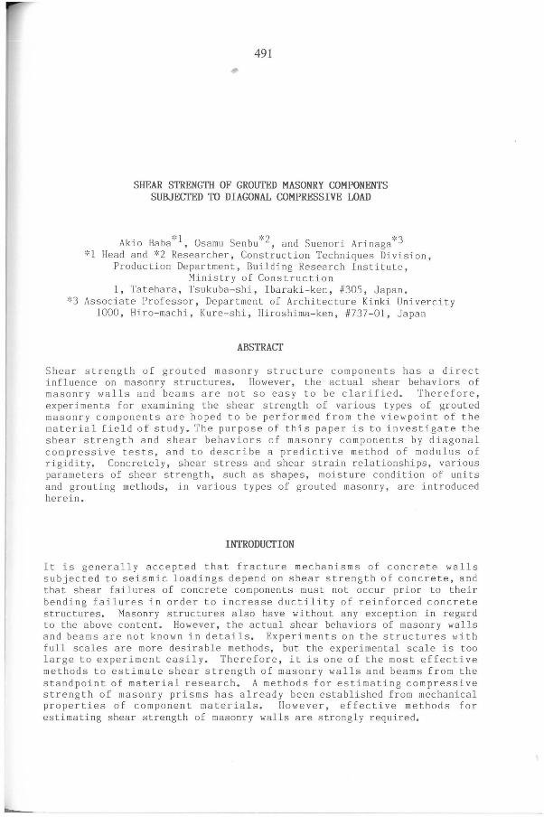
S pecimens Masonry components used in experiments are shown in Table 1. Units are clay and concrete which are d ifferent in s hape or compressive strength. Grou t ing materiaIs used in constructing specimens are mortar and concrete. One series of experiments is prepared to examine the difference between mortar joint method and casting joint one. One series of a clay unit M was prewe t ted sufficiently prior to grouting . The other series was grouted in an air dried condition.
D ~ j
I ~ I
I I
I I
I --- -- --- ---
---]
~
o ~ Standard Type Wall Type Beam Ty pe
Figur e 1 Three Shapes of Specimens for Diagonal Compressive Tests
As showen i n Figure 1, the shape of specimens is classified into three types of standard , wall and beam type by the aspect ratio. On the dimensions of specimens , the standard type of some units has three sizes, 60x60, 90x90, 120x120cm . Wa1 1 type and beam type are one size for each. The former is 120x60cm,and the latter is 60x120cm •
..
-
493
Table Masonry Units Used in Experiments
Name of Condition Shape of Specimens Construction Specimens of Unit at Laying Methods
Units Grouting Type Aspect Ratio Grout Joint
MMll Standard 1: 1 MM12 Beam 1: 2 MM2l Wet Ivall 2:1 Mortar Mortar Joint MM22
Clay MM33 Standard 1: 1 Unit M
MD11 Standard 1: 1 MD12 Dry Beam 1:2 Concrete Mortar Joint MD21 Wall 2:1
MIl Wet Standard 1: 1
Clay Nll Standard 1: 1 Unit N N12 Dry Beam 1:2 Mortar Mortar Joint
N2l Wall 2:1
411 Standard 1: 1 Concrete 412 Beam 1:2
Unit S4 421 Dry Wall 2:1 Concrete Mortar Joint 422 Standard 1: 1 433 Standard 1: 1
Concrete 511 Standard 1: 1 Unit S5 512 Dry Beam 1:2 Cncrete Mortar Joint
521 Wall 2:1
CO 11 Standard 1: 1 C012 Dry Beam 1:2 - Mortar Joint
Concrete C02l Wall 2:1 Unit C
Cll Standard 1: 1 C12 Dry Beam 1:2 Mortar Mortar Joint C21 Wall 2:1
AlI Standard 1: 1 A12 Dry Beam 1:2 Mortar Mortar Joint
Concrete A2l Wall 2:1 Unit A
ACll Standard 1: 1 AC12 Dry Beam 1:2 Mortar Casting Joint AC21 Wall 2: 1
-
494
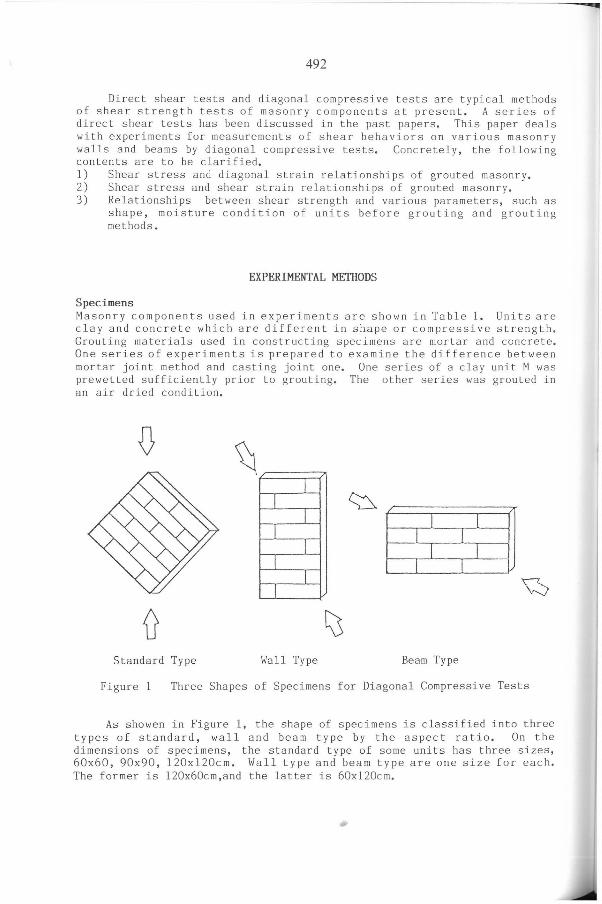
Loading and Measurements Diagonal compressive tests for estimsting shear strength and deformations of masonry components are performed by applying a compressive force to the specimens diagonally. A loading machine with rigid reaction frames, whose capacity was lOOOt, was used. Each specimen was capped with gypsum plaster and the diagonal compressive test was practiced after the gypsum plaster harden.
Measuring methods of strains are shown in Figure 2. As shown in this figure, strains of every specimen were obtained by displacement transducers and wire strain gages. Displacement transducers were set on the two diagonaIs of specimens for measuring the average of strains in the two directions. Wire strain gages were to measure strains in the three directions of vertical, horizontal and diagonal at the center of specimens. Strains of various parts of a specimen named MM33 were measured to examine the stress distribution in the vertical and horizontal direction •
Figure 2
.z>. Load
Cap
..c: w 00 c: QJ -l
00 c:
-ri H ;::J Ul CI) QJ
z
____ 1
{f
Diagonal Compressive Tests
RESULTS AND DISCUSSIONS
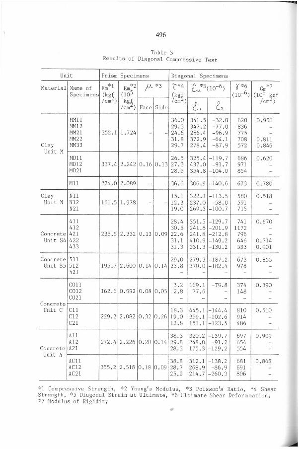
Experimental Results on Shear Strength The properties of units and grouting materiaIs used in this experiment are shown in Table 2. The results of diagonal compressive tests are summarized in Table 3 including that of prism tests.
-
L
495
Table 2 Properties of Units and Grout
Unit and Grout Compres2ive Strength Youn§'s Modu~us Volumetic (kgf/cm ) (':<10 kgf/cm) Ratio of Voids
Clay Unit M 489 1.72 0.634 Clay Unit N - - 0.178
Concrete Unit S4 304 1.92 0.561 Concrete Unit S5 371 2.52 0.509
Concrete Unit C 333 2.32 0.431 Concrete Unit A 439 3.28 0.598 Grout (Mortar) 279 2.77 -
Grout (Cncrete) 257 2.03 -
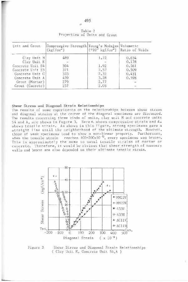
Shear Stress and Diagonal Strain Relationships The results of some experiments on the relationships between shear stress and diagonal strains at the center of the diagonal specimens are discussed. The results concerning three kinds of units, clay unit M and concrete units S4 and A, are shown in Fugure 3. Here E.\ shows compressive strain and E;~ shows tensile strain. As shown in this figure, strong specimens gave a straigh t line until the neighberhood of the ultimate strength. However, those of weak specimens tend to show a non-linear property. Furthermore, when the tensile strain reaches 100-200x10-6 , every specimens was broken. This is approximately the same to usual tensile strains of mortar or concre te. Therefore, it would be obvious that shear strength of masonry walls and beams are also depended on their ultimate tensile strain.
Ten
5 o
E ,
4 lJ.
o ~
lJ. A
li it. ,-----Ed> t---r
rrr.. s 30 4 El
~
."J: ~+ ."'+~
rn o. ~
rA: / :.: ZL \ l1. o lJ.
,oi; .,-
, w1 + q .' /+
o 20
o ~ .~ ." 1 °rf--J' / .0 ~ ~i
~!~ o-n
+- MM22V
o-MM22H
·-433V
D-433H
10- ACll V
lJ.- ACllH C
-200 -100 o 100 200 300 400 om.
500
Figure 3
Diagonal Strain
Shear Stress and Diagonal Strain Relationships ( Clay Unit M, Concrete Unit S4,A )
496
Table 3 Results of Diagonal Compressive Test
Unit Prism Specimens Diagonal Specimens
Material Name of Fm*l Em"'2 fi'- '~3 L*4 [,;?( 10-6) O' '~6 '~7
Specimens (kg~ (lOS (kg~ (10-6) (lg~ kgf /cm ) kgf /cm ) t, (7..
/cm2) /cm2) Face Side
MMll 36 .0 341.5 -32.8 620 0.956 MM12 29.3 347.2 -77.0 836 -MM21 352. 1 1.724 - - 24.6 286.4 - 96.9 775 -MM22 31.8 372.9 -64 .1 708 0.811
Clay MM33 29 . 7 278.4 - 87.9 572 0.846 Unit M
MDll 26.5 325 .4 -119.7 686 0.620 MD12 337.4 2.242 0.16 0.13 27.3 437.0 - 91.7 971 -MD2 1 28.5 354.8 -104.0 854 -
M11 274.0 2.089 - - 36.6 306.9 -140 .6 673 0.780
Clay N11 15.1 322.1 - 113.5 580 0.518 Unit N N12 161.5 1.978 - - 12.3 237.0 -58 .0 591 -
N21 19.0 269.3 -100 .7 715 -
411 28.4 351.5 -1 29.7 741 0.670 412 30.5 241.8 - 201.9 1172 -
Concrete 421 235 . 5 2. 332 0 . 13 0 . 09 22 . 6 241.8 -212.8 796 -Unit S4 422 31.1 410.9 -149 .2 646 0.714
433 31.3 231.3 -130.2 533 0.901
Concrete 511 29.0 279.3 -187.2 673 0.855 Unit S5 512 195.7 2.600 0.14 0.14 23.8 370.0 -182.4 978 -
521 - - - - -
C011 3.2 169.1 -79 .8 374 0.390 C012 162.6 0.992 0.08 0.05 2.8 77 .6 - 148 -C021 - - - - -
Concrete Unit C C11 18.3 445.1 -144.4 810 0.510
C12 229.2 2.082 0.32 0.26 19.0 359 .1 -102.6 914 -C2 1 12.8 151.1 -1 23.5 486 -
A11 38.3 320.2 -1 39.7 697 0.909 A12 272 .4 2. 226 0.20 0 .14 29 .8 248.0 -91. 2 654 -
Concrete A21 28.3 175.3 -129 . 2 554 -Unit A
ACll 38.8 312.1 -138.2 681 0.868 AC12 355.2 2.518 0.18 0.09 28.7 268.9 -86 .9 691 -AC21 25.9 214.7 -260.3 806 -
':' 1 Compressive Strength, *2 Young 's Modulus, '~3 Poisson 's Ratio, '~4 Shear Strength, *5 Diagonal Strain at Ultimate , *6 Ultimate Shear Deformmation, *7 Modulus of Rigidity
.....
497
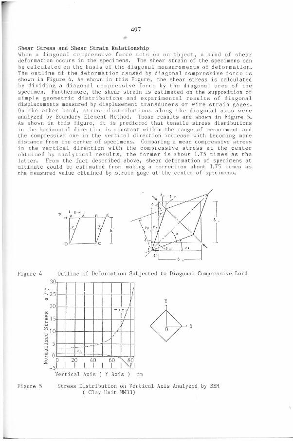
Shear Stress and Shear Strain Relationship When a diagonal compressive force acts on an object, a kind of shear deformation occurs in the specimens. The shear strain of the specimens can be calculated on the basis of the diagonal measurements of deformation. The outline of the deformation caused by diagonal com pressive force is shown in Figure 4. As shown in this Figure, the shear stress is calculated by dividing a diagonal compressive force by the diagonal area of the specimen. Furthermore, the shear strain is estimated on the supposition of simple geometric distributions and exparimental results of diagonal displacements measured by displasement transducers or wire strain gages. On the other hand, stress distributions along the diagonal axis were analyzed by Boundary Element Method. Those results are shown in Figure 5. As shown in this figure, it is predicted that tensile stress disributions in the horizontal direction is constant within the range of mesurement and the compressive one in the vertical direction increase with becoming more distance from the center of specimens. Comparing a mean compressive stress in the vertical direction with the comp ressive stress at the center obtained by analytical results, the former is about 1.75 times as the latter. From the fact described above, shear deformation of speci mens at ultimate could be estimated from making a correction about 1.75 times as the measured value obtained by strain gage at the center of specimens.
Figure 4
Figure 5
30
/-J ....... 25 b
20 Ul
~ 15 ... +J
(/)10 "O Q)
.~ 5 M co E O
1 L ,
J ~ ,
, y,
't
/
Outline of Deformation Subjected to Diagonal Compressive Lord
i Y
I
- ~ y "
I /
/ , , .-.' <!7 x
--" . ..
-- -- --~x
o z O 20 40 60 ~Ol
-5 I I I I I I I Vertical Axis ( Y Axis ) cm
Stress Distribution on Vertical Axis Analyzed by BEM ( Clay Unit MM33)
498
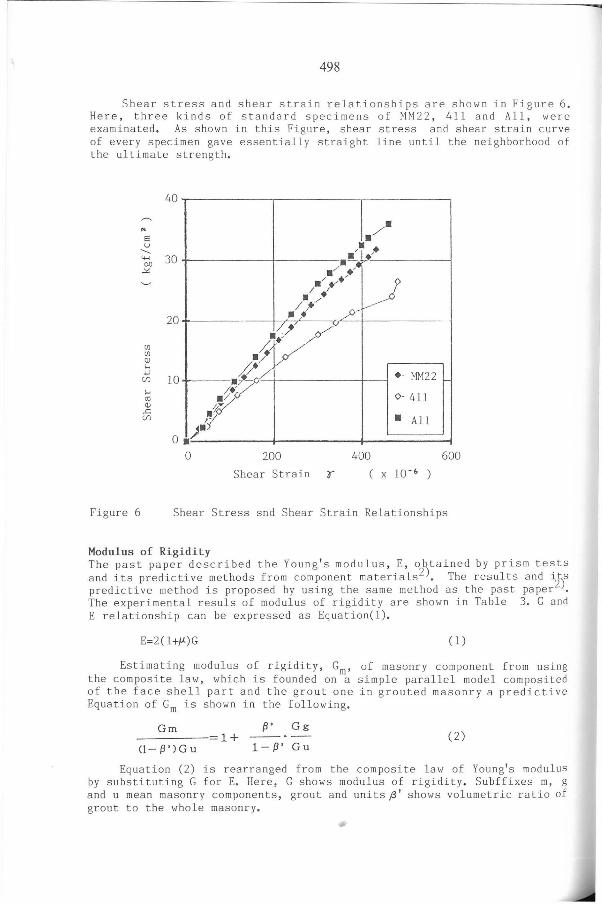
Shear stress and shear strain relationships are shown in Figure 6. Here, three kinds of standard specimens of MM22, 411 and AlI, were examinated. As shown in this Figure, shear stress an d shea r strai n curve of every specimen gave essen tially straight line until the neighborhood of the ultimate strength.
.. E U
----
40
6'0 30 ~
20
[fj [fj Q) ... '-'
Cf} 10 ... til Q) .c Cf}
O
. / • • ./ ,.,.
/ • • --:ti . / ./~. 1
.1/./ v-""' // p-...
J~-' /,)
.tv .- MM22
/.{7' 0- 411 I~/
./0 . - All r'/
)ai • O 200 400 600
Shear Strain o x 1O-~ )
Figure 6 Shear Stress snd Shear Strain Relationships
Modulus of Rigidity The pa st paper described the Young's modulus, E, o~tained by prism tests an d its predictive methods from component materia l s 2 • The results and i 0S
predictive method is proposed by using the same method as the past paper2 • The experimental r esuls of modulus of rigidity are show n in Table 3. G and E relationship can be expressed as Equation(l).
E=2(1+,U)G (1)
Estimating modulus of rigidity, Gm, of masonry component fro m using the composite law, which is founded on a simple parallel model composited of the face shell par t and the gro ut one in gro ut ed ma sonry a predictive Equation of Gm is shown in the following.
Gm {J' Gg (2) 1+
(1- {plGu 1-{J' Gu
Equation (2) is rearranged fro m the composi t e law of Young ' s modulus by substituting G for E. Here, G s hows modulus of rigidity. Subffixes m, g and u mean masonry components, grou t and unit s (3' shows volumetr ic ratio of grout to the whole masonry.
li'
-
-
499
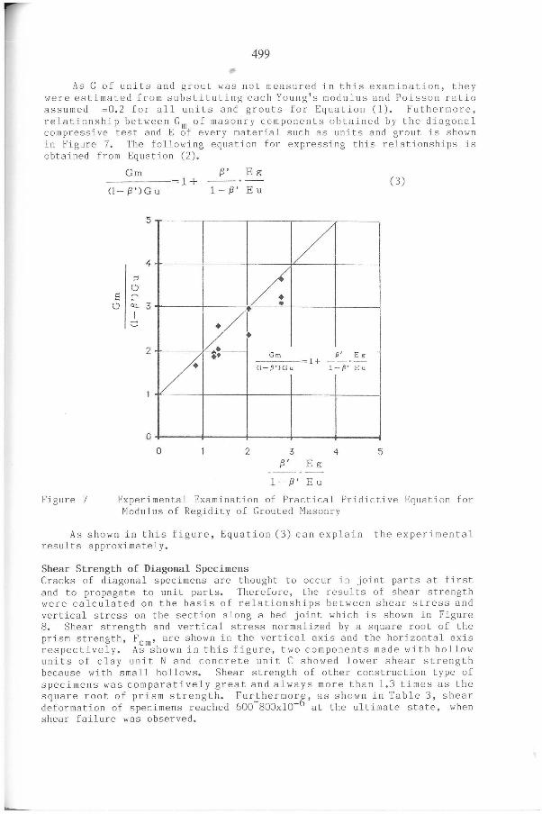
As G of units and grout was not measured in this examination, they were estimated from substituting each Young's modulus and Poisson ratio assumed =0.2 for alI units and grouts for Equation (1). Futhermore, relationship between Gm of masonry components obtained by the diagonal compressive test and E of every material such as units and grout is shown in Figure 7. The following equation for expressing this relationships is obtai ned from Equation (2).
Figure 7
Gm {3' Eg 1+ -_.- (3)
(1- (3') G u l-{3' Eu
5
4
r--
1/ ~
O E:
O cu. 3 / I
C
2 L /
;. Gm p' Eg 1+ -_.-
(l-p')Gu 1-P' Eu
o o 2 3 4 5
{3' E g
1- {3' Eu
Experimental Exam ination of Practical Pridictive Equation for Modulus of Regidity of Grouted Masonry
As shown in this figure, Equation (3) can explain the experimental results approximately.
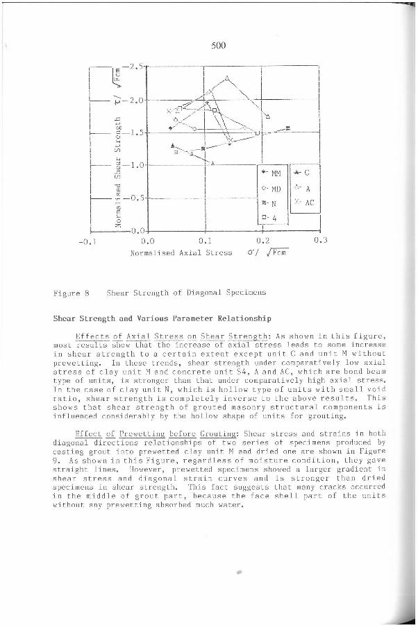
Shear Strength of Diagonal Specimens Cracks of diagonal specimens are thought to occur in joint parts at first and to propagate to unit parts. Therefore, the r esults of shear strength were calculated on the basis of relationships between shear stress and vertical stress on the section along a bed joint which is shown in Figure S. Shear strength and vertical stress normalized by a square root of the prism strength, Fcm' are shown in the vertical axis and the horizontal axis respectively. As shown in this figure, two components made with hollow units of clay unit N and concrete unit C showed lower shear strength because with small hollows. Shear strength of other construction type of specimens was comparatively great and always more than 1.3 times as the square root of prism strength. Furthermorg, as shown in Table 3, shear deformation of specimens reached 600-S00x10- at the ultimate state, when shear failure was observed.
500
1--~-2.5 I I I lu", I I I '"'" I // .......... I
I v ' I I - AI. I
1_. - 1-> - 2.0 ._.,0> L->:'" " .. ") I Q'~" '. I ", .,;:. - ... - ·I-~\-.··!::o i II '5 .~>.:.~.-. . ~ ..... -- ;:-'" I _-: I
0.0 ~ , --.- ~ - 0+-1 ,.--=-= ___ . f--.- c: -1.5 \:'. _- _ T I 'li ~ • . .1 ------~:~- I I
J,...l ---o _~_
~- ~-1.0 ·~·-I-' :: l:~ I r-- ª -0.5 i >1- N :.:- AC
I ~ I ~- 4 I j ;Z; O O l •
- 0.1 0.0 0.1 0.2 0.3
Normalised Axial Stress (í / jFcm
Figure 8 Shear Strength of Diagonal Specimens
Shear Strength and Various Parameter Relationship
Effects ~ Axial Stress ~ Shear Strength: As shown in this figure , most results show that the increase ofaxial stress leads to some increase in shear strength to a certain extent except unit C and unit M without prewetting. In these trends, shear strength under comparatively low axial stress of clay unit M and concrete unit S4, A and AC, which are bond beam type of units, is stronger than that under comparatively high axial stres s. In the case of clay unit N, which is hollow type of units with small void ratio, shear strength is completely inverse to the above results. This shows that shear strength of grouted masonry structural components is influenced considerably by the hollow shape of units for grouting.
Effect of Prewetting before Grouting: Shear stress and strains in both diagonal directions relationships of two se r ies of specimens produced by casting grout into prewetted clay unit M and dried one are shown in Figure 9. As shown in this Figure, regardless of moisture condition , they gave straight lines. However, prewetted specimens showed a larger gradient i n shear stress and diagonal strain curves and is stronger than dried specimens in shear strength. This fact suggests that many cracks occurred in the middle of grout part , beca use the face shell part of the units without any prewetting absorbed much water •
•
......
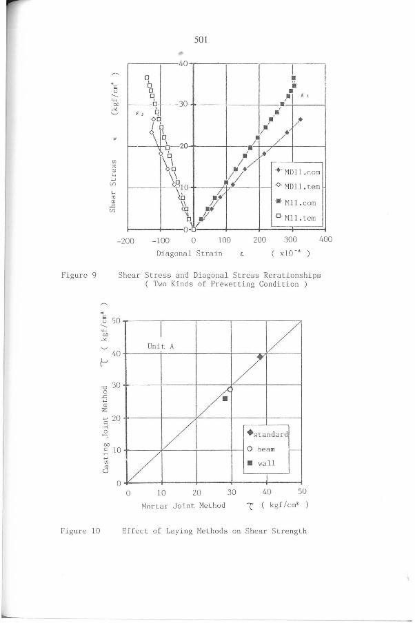
Figure 9
Figure 10
501
40
" E: ~q~30 u '-"-'
O(J
~ E 2 q
I • .. • • E !
/ ,. •
00 f b • v· / •
--4 ~
I-- °q_ 20 C/l \b C/l QJ ...
\~1O '-' (/)
... co QJ
..c
.I / . • I / • ~ , • /./
-. - MDl l. com .'l -O- MDl l. tem .~/
-. - Mll. com \~b (/)
\\ .1
1/
"
O .' 'I U Ml l. tem
O -o -200 - 100 o 100 200 300 400
Diagonal Strain
Shear Stress and Diagona l St r es s Rerations hi ps ( Two Kinds of Prewetting Co nd i t ion )
5 50
I V '-"-'
O(J
~
Un i t A 40
~
-o 30 o
..c '-' QJ
::E:
'-' 20 c:: -r< o ....., O(J
c:: 10 -r< '-' C/l co
U
O
/ /"
/ + standa r d
O beam ,---
/ • wall
O 10 20 30 40 50
Mortar Joint Met hod l ( kgf/cm2 )
Effect of Laying Methods on Shear Strength
502
Effect Qi laying Methods: The results of shear strength between a mortar joint method and a casting joint method with a concrete unit A are shown in Figure 10. In this figure, the casting joi nt method is little different from the mortar joint method in shear strength, so casting joint methods are thought to be one of new useful methods as the substitute of mortar joint methods.
CONCLUSIONS
The experiments and disccusions mentioned above are summarized as follows.
(1) Diagonal specimens with high strength give stra ight lines to the neighborhood of ultimate strength as the stress and strain curve, but that with lower strength tends to show a non-linear property in shear stress and d~agonal s6rain curve. Fur therm ore, whe n tensile strain reaches 100 150xlO- , most grouted masonry specimens suffer from major shear cracks.
(2) A composite law concerni ng modulus of rigidity of grouted masonry is proposed.
(3) Shear strength of grouted masonry specimens with comparatively large hollow is clarified to be more than 1.3 times of the square root of comyressivg strength. Futhermore, when shear deformation reaches 600 600xlO- , diagonal specimens tend to show shear failures.
(4) Shear strength of grouted masonry with comparatively large hollows shows some increments with a certain axial stress.
(5) A casting joint method is little different from a mortar joint method in shear strength in the case of a strong concrete unit.
REFERENCES
1. A. Baba, M. Watanabe and O.Senbu, " An Experiment on Direct Shear Strength and Slip Deformation of Joint Part in Masonry Wall," Second Joint Technical Coordinating Committee on Masonry Reseach, Keyston, Co l orado, USA , september, 1986.
2. A. Baba a nd O. Senbu, " A Predictive Method of Prism Strength of Grouted Masonry," di t to.