wind generation and its grid conection
TRANSCRIPT
07/04/2016
1
Wind Generation and its Grid
Conection
J.B. EkanayakePhD, FIET, SMIEEE
Department of Electrical and Electronic Eng.,
University of Peradeniya
Content
• Wind turbine basics
• Wind generators
• Why variable speed?
• Grid Code requirements
• Concluding remarks

07/04/2016
2
Introduction
http://www.wwindea.org/hyr2015/
124
67.8
42.423.8
23
13.3
10.2
87.8
China USA Germany India Spain UK Canada RoW
Worldwide wind capacity as at mid of 2015 = 393 GW
WIND TURBINE BASICS
07/04/2016
3
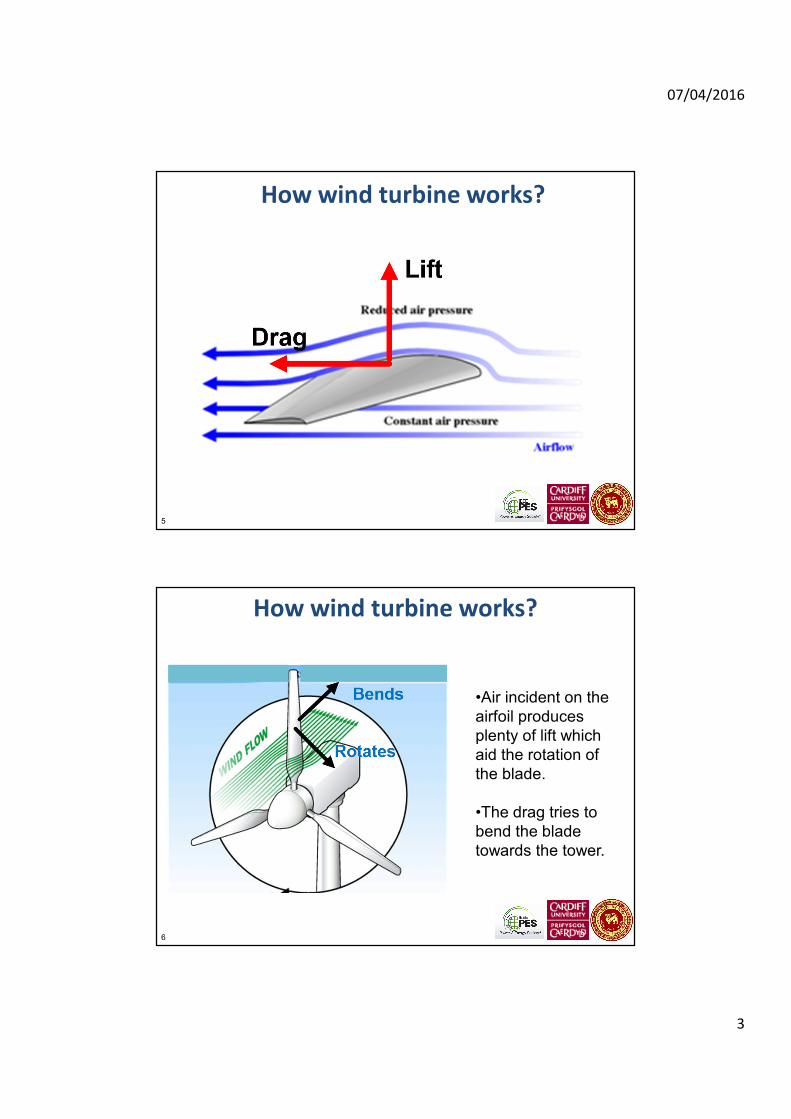
How wind turbine works?
5
How wind turbine works?
6
•Air incident on the
airfoil produces
plenty of lift which
aid the rotation of
the blade.
•The drag tries to
bend the blade
towards the tower.

07/04/2016
4
Power available in a wind stream
• The kinetic energy in a flow of
air = per unit mass
• Mass flow rate= (kg/s)
– is the air density in kg/m3
• Power available in the wind
stream =
21
1
2U
1AUρ
ρ
31
1
2AUρ
Energy- extracted by the wind turbine
• Power extracted by the aerodynamic rotor = Cp x
Power available
• Cp is the coefficient of performance
• The Betz limit: Maximum value of the coefficient
of performance Cp
is 59%.
• Cp depends on the tip speed ratio
Velocity at rotor tip
Wind velocity
R
U
ωλ = =

07/04/2016
5
Cp vs Tip speed ratio
Variable speed operation
To extract maximum power ωr should vary with the wind speed
0 0.2 0.4 0.6 0.8 1 1.20
0.2
0.4
0.6
0.8
1
1.2
1.4
Generator rotational speed (pu)
Po
we
r (p
u)
5 m/s6 m/s
7 m/s
8 m/s
9 m/s
10 m/s
11 m/s
12 m/s
13 m/sGenerator speed in pu
1440/1800 = 0.8 pu
Maximum power that can
be extracted

07/04/2016
6
Evolution of Wind Turbine Technologies
Available wind turbines
Turbine Capacity Generator Rotor diameter Geared
Vestas V164 8 MW FPC 164 m Yes
Enercon E126 7.5 MW FPC 127 m No
Repower 6M 6 MW DFIG 126 m Yes
Siemens SWT-6.0 150 6 MW FPC - PMG 154 m No
Alstom Haliade 150 6 MW FPC - PMG 150 m No
Areva M5000 5 MW FPC - PMG 135 m Yes
Gamesa G128 5 MW FPC - PMG 128 m Yes
http://en.wind-turbine-models.com/
07/04/2016
7
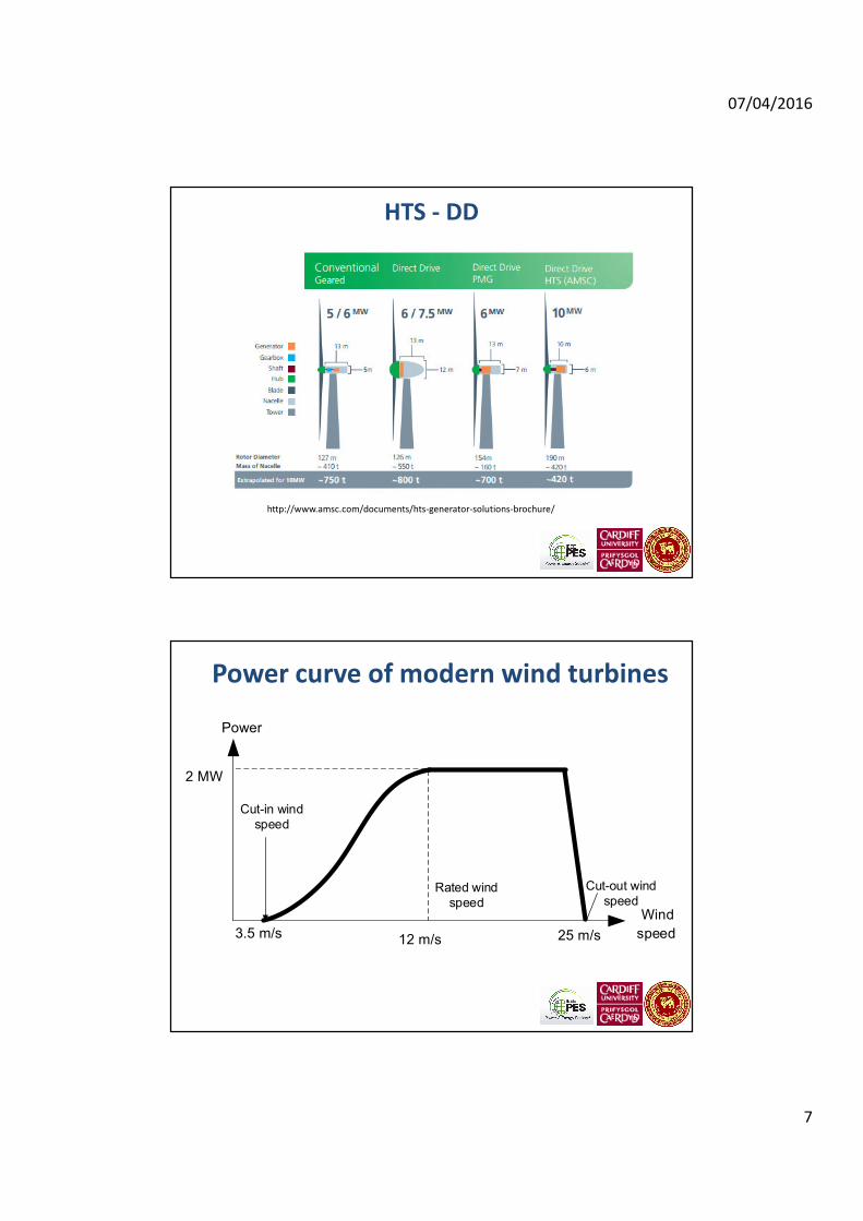
HTS - DD
http://www.amsc.com/documents/hts-generator-solutions-brochure/
Power curve of modern wind turbines
2 MW
Power
Wind
speed12 m/s 25 m/s
Cut-in wind
speed
Rated wind
speed
3.5 m/s
Cut-out wind
speed

07/04/2016
8
Control of modern wind generators
� Wind speed 7 to 15 m/s Electronic control
� Wind speed above 15 m/s Pitch control
� Input aerodynamic power is reduced by increasing the pitch angle at
high wind speed
3.5 m/s
WIND GENERATORS
16

07/04/2016
9
Fixed speed wind turbine
Variable speed wind turbines
Turbine
Gear
box
Wound rotor
induction
generator
Back-to-Back
VSCs connected
to the rotor
Induction or
synchronous
generator
Diode bridge and
a VSC connected
to the stator
Multi-pole
permanent magnet
synchronous
generator
Doubly-Fed Induction
Generator
Geared Full Power
Converter
Gearless Full Power
Converter
Back-to-Back
VSCs connected
to the stator

07/04/2016
10
Doubly-fed arrangement
• Variable speed operation is possible by absorbing or injecting slip power using an external means.
• The sub-synchronous or super-synchronous speeds can be obtained by feeding in or taking out electric power to/from the rotor.
• This is normally done by injecting a voltage into the rotor circuit through slip rings.
Zero rotor injection
Operates as a fixed speed machine
jXrRr/s
sE2
-0.4 -0.3 -0.2 -0.1 0 0.1 0.2 0.3 0.4 -15
-10
-5
0
5
10
Slip (pu)
To
rqu
e (p
u)
07/04/2016
11
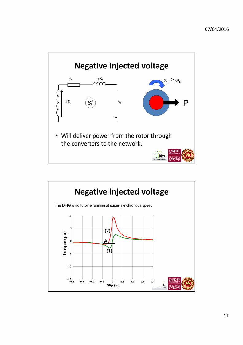
Negative injected voltage
• Will deliver power from the rotor through
the converters to the network.
jsXrRr
sE2 P
ωr > ωs
sf Vr
Negative injected voltage
-0.4 -0.3 -0.2 -0.1 0 0.1 0.2 0.3 0.4 -15
-10
-5
0
5
10
Slip (pu)
To
rqu
e (
pu
)
(1)
(2)
A
The DFIG wind turbine running at super-synchronous speed

07/04/2016
12
Positive injected voltage
The DFIG rotor absorbs power.
jsXrRr
sE2 P
ωr < ωs
sf Vr
Slip – torque curve
The DFIG wind turbine running at sub-synchronous speed
-0.4 -0.3 -0.2 -0.1 0 0.1 0.2 0.3 0.4 -15
-10
-5
0
5
10
Slip (pu)
Torq
ue
(pu
)
(1)
(2)
(3)
AB

07/04/2016
13
Doubly fed induction generator (DFIG)
25
rv
ri
sv
si a
i
gi
Controller
ac / dc dc / ac
C1 C2
av
ggjQP +
DFIG
• Converter C1 inverts dc voltage into slip
frequency ac
• It can inject both positive and negative
voltages by properly controlling the
switching signals
• Converter C2 maintains a constant voltage
on the DC capacitor
07/04/2016
14
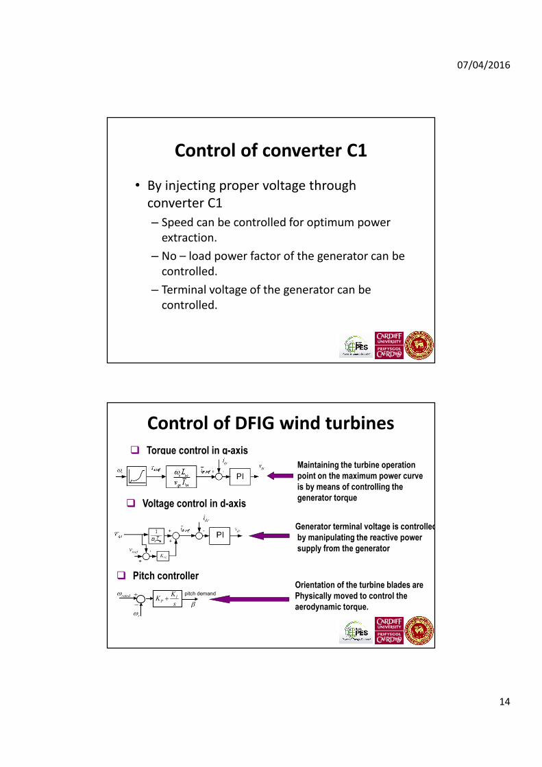
Control of converter C1
• By injecting proper voltage through
converter C1
– Speed can be controlled for optimum power
extraction.
– No – load power factor of the generator can be
controlled.
– Terminal voltage of the generator can be
controlled.
� Torque control in q-axis
� Voltage control in d-axis
ωrated
ωr
+
−+ I
P
KK
s β
pitch demand
� Pitch controller
Maintaining the turbine operation
point on the maximum power curve
is by means of controlling the
generator torque
Generator terminal voltage is controlled
by manipulating the reactive power
supply from the generator
Orientation of the turbine blades are
Physically moved to control the
aerodynamic torque.
Control of DFIG wind turbines
07/04/2016
15
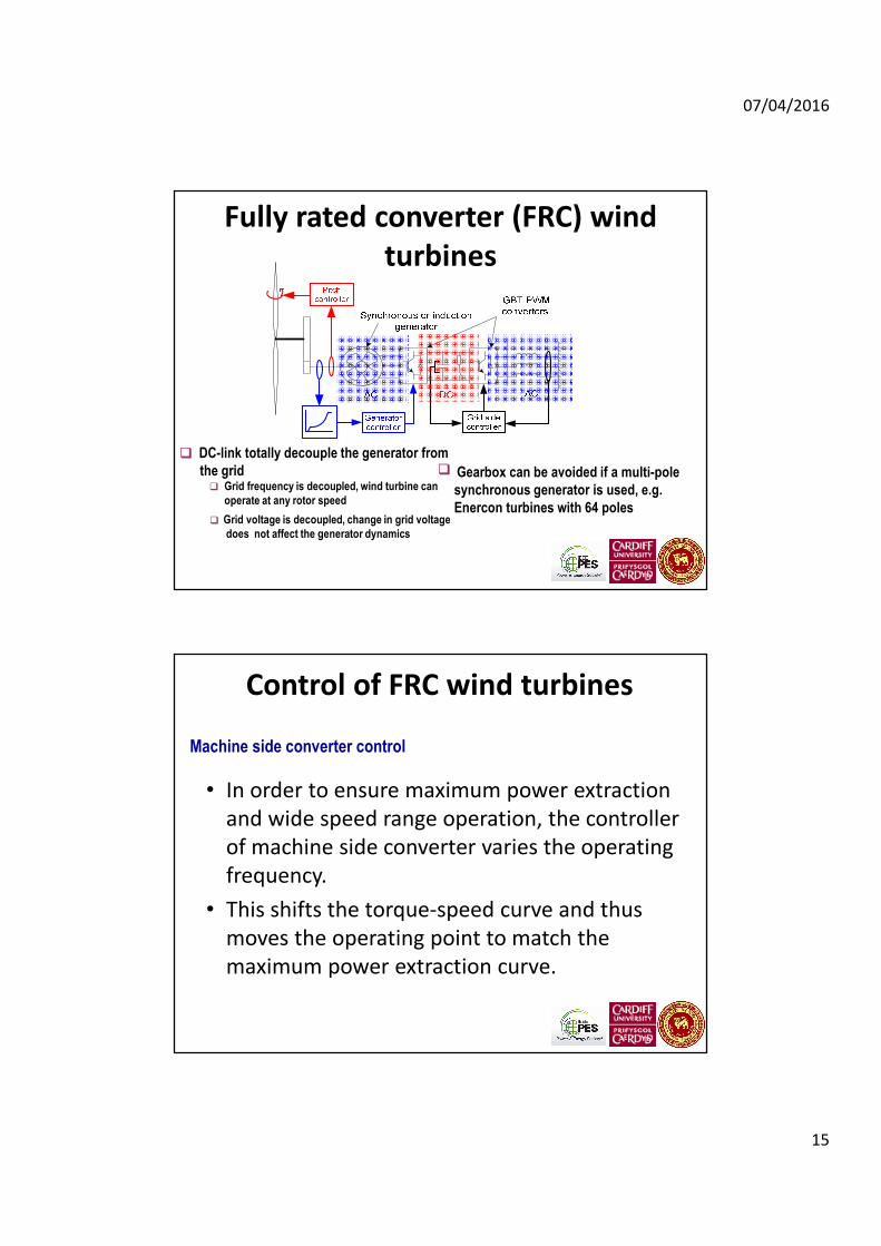
Fully rated converter (FRC) wind
turbines
�
�
� DC-link totally decouple the generator from
the gridGrid frequency is decoupled, wind turbine can
operate at any rotor speed
Grid voltage is decoupled, change in grid voltage
does not affect the generator dynamics
� Gearbox can be avoided if a multi-pole
synchronous generator is used, e.g.
Enercon turbines with 64 poles
Control of FRC wind turbines
• In order to ensure maximum power extraction
and wide speed range operation, the controller
of machine side converter varies the operating
frequency.
• This shifts the torque-speed curve and thus
moves the operating point to match the
maximum power extraction curve.
Machine side converter control
07/04/2016
16
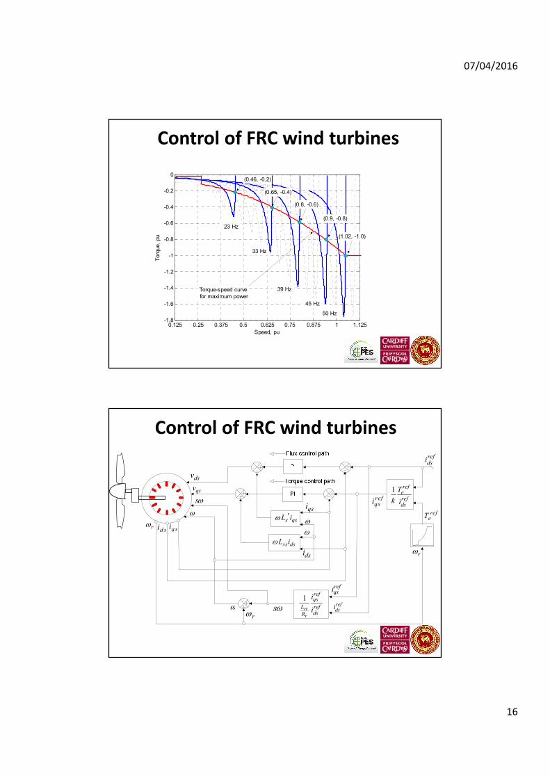
Control of FRC wind turbines
1.12510.8750.75 0.6250.5 0.3750.250.125-1.8
-1.6
-1.4
-1.2
-1
-0.8
-0.6
-0.4
-0.2
0
Speed, pu
Torq
ue,
pu
Torque-speed curve
for maximum power
50 Hz
45 Hz
39 Hz
33 Hz
23 Hz
(0.46, -0.2)
(0.65, -0.4)
(0.8, -0.6)
(0.9, -0.8)
(1.02, -1.0)
Control of FRC wind turbines
s qsL iω ′
ss dsL iω
1
rr
r
refqs
L refdsR
i
i
1referefds
T
k i
rω
dsv
qsv
sω
ω
qsid sirω
refqsi
refeT
ω sωrω
refqsi
refdsi
ω
dsi
qsi
ω
refdsi
07/04/2016
17
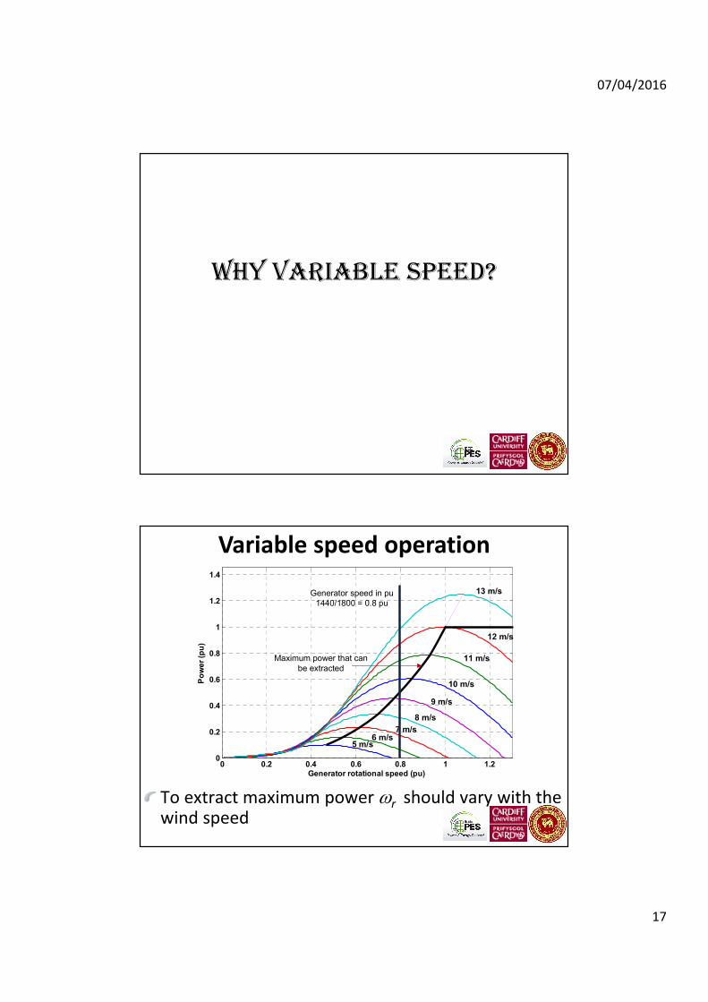
WHY VARIABLE SPEED?
Variable speed operation
To extract maximum power ωr should vary with the wind speed
0 0.2 0.4 0.6 0.8 1 1.20
0.2
0.4
0.6
0.8
1
1.2
1.4
Generator rotational speed (pu)
Po
we
r (p
u)
5 m/s6 m/s
7 m/s
8 m/s
9 m/s
10 m/s
11 m/s
12 m/s
13 m/sGenerator speed in pu
1440/1800 = 0.8 pu
Maximum power that can
be extracted

07/04/2016
18
Power output
Forces on wind turbines
Blade Flapwise bending
Aerodynamic forces in flapwise
direction
Blade Edgewise bending
Gravity forces
Aerodynamic forces in edgewise
direction
Loads on Blades
Loads on Rotor Hub
In-plane bending moments of the blades
Out-of-plane bending moments of the
blades
Drive train interaction – torque
fluctuations due to control action
Loads on Tower
Axial bending moment

07/04/2016
19
Forces on wind turbines
Blade x direction
Blade y direction
Blade z direction
Fixed speed
Variable speed
GRID CODE REQUIREMENTS
07/04/2016
20
39
• Grid Codes specify the mandatory minimum technical
requirements that a power plant should fulfil and
additional support that may be called on to maintain
the second-by-second power balance and maintain
the required level of quality and security of the system.
• Grid Codes for wind farm connections demand
requirements at the point of connection of the wind
farm not at the individual wind turbine generator
terminals.
Grid Codes
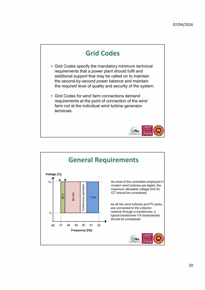
General Requirements
46 48 5047 49 51 52
Voltage [%]
Frequency [Hz]
1 min
Con
tin
uou
s o
pe
ratio
n
AVH
VL
B
30 s
60 m
in
As most of the controllers employed in
modern wind turbines are digital, the
maximum allowable voltage limit for
ICT should be considered.
As all the wind turbines and PV parks
are connected to the collector
network through a transformer, a
typical transformer V/f characteristic
should be considered.

07/04/2016
21
General Requirements
ITI (CBEMA) Curve
V/f characteristics of transformers
Active power control
Ireland, India, Denmark and
Germany
UK
Active p
ow
er
ou
tput a
s a
% o
f
ava
ilable
pow
er
Frequency
PA
PB
PD
Ireland 47 (min) 49.5 50.5 52
Denmark 47 (min) 49.9 50.1 53
India 50.3
Germany 50.2

07/04/2016
22
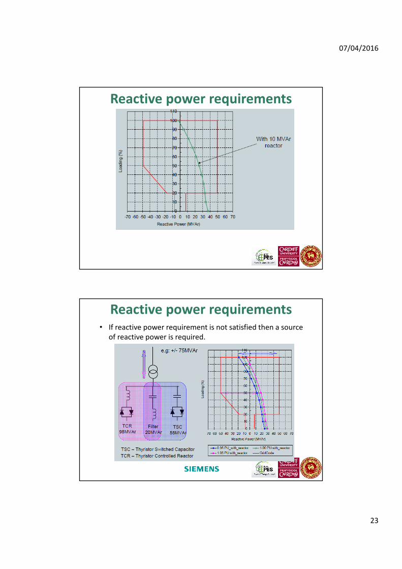
Reactive Power and Voltage Control
Reactive power requirements
07/04/2016
23
Reactive power requirements
Reactive power requirements• If reactive power requirement is not satisfied then a source
of reactive power is required.
07/04/2016
24
• With the penetration of wind generation increasing, Grid Codes now
generally demand Fault Ride-Through capability for wind turbines
connected to transmission networks.
• What is FRT?
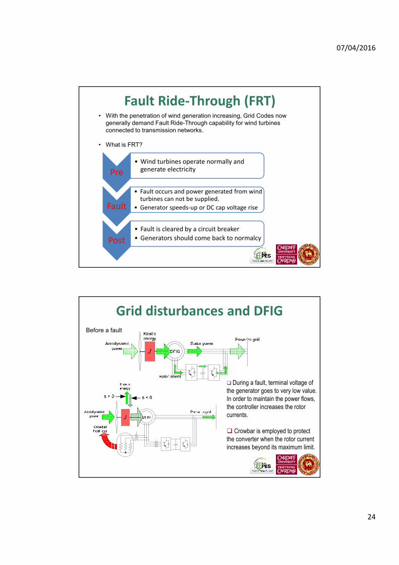
Fault Ride-Through (FRT)
Pre
• Wind turbines operate normally and generate electricity
Fault
• Fault occurs and power generated from wind turbines can not be supplied.
• Generator speeds-up or DC cap voltage rise
Post
• Fault is cleared by a circuit breaker
• Generators should come back to normalcy
Grid disturbances and DFIG
J
J
Before a fault
� During a fault, terminal voltage of
the generator goes to very low value.
In order to maintain the power flows,
the controller increases the rotor
currents.
� Crowbar is employed to protect
the converter when the rotor current
increases beyond its maximum limit.

07/04/2016
25
Grid disturbances and Full range
GEpGRpCp
dcv
C
DCR
DCRp
J
Chopper resistor at the DC-link
� During a fault, power to the grid is limited
� DC-link voltage rises rapidly
� Input power has to be reduced or excessive
power has to be dissipated
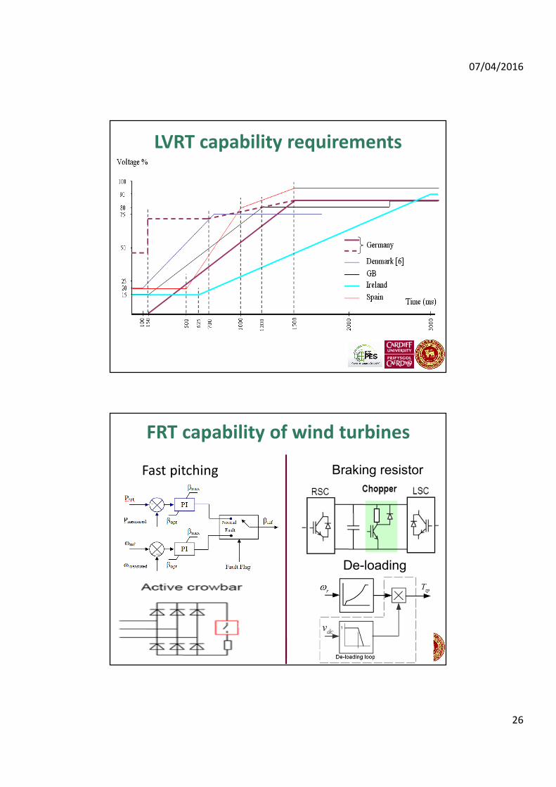
LVRT capability
The wind farm and any constituent wind turbine
generating unit must remain transiently stable and
connected to the system without tripping for balanced
voltage dips and associated durations anywhere on or
above the heavy black line
07/04/2016
26
LVRT capability requirements
FRT capability of wind turbines
Fast pitching
De-loading
Braking resistor
07/04/2016
27
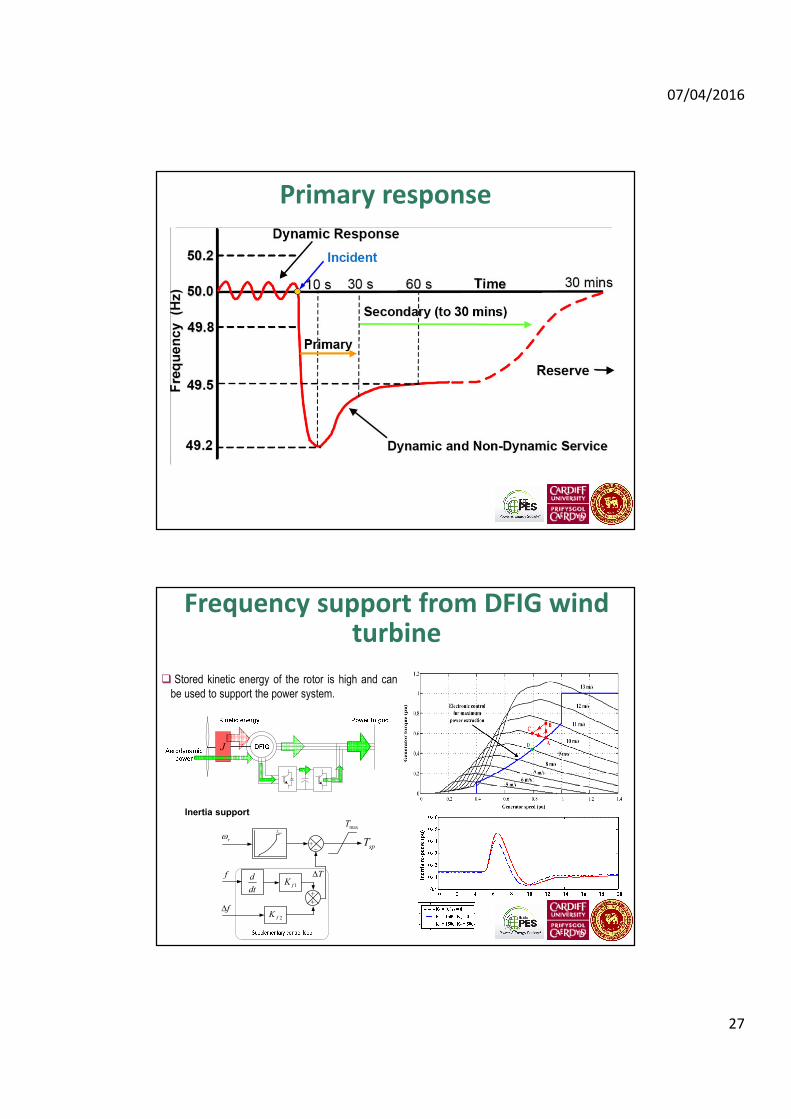
Primary response
f T∆d
dt
spTrω
2fK
1fK
f∆
+−
+
+
maxT
maxT
J
Frequency support from DFIG wind turbine
� Stored kinetic energy of the rotor is high and can
be used to support the power system.
Inertia support

07/04/2016
28
Concluding remarks
• Penetration of wind generation is increasing
• Large wind turbines and new technologies are
emerging
• Utilities now expect wind farms to perform
exactly like a large synchronous generator
– This demands extra plants to be connected at the
point of connection
– In turn the CAPEX will increase
Thank you
You are invited to 600 acres beautiful campus
University of Peradeniya, Sri Lanka