galloper wind farm eastern super grid transformer project · galloper wind farm eastern super grid...
TRANSCRIPT
Galloper Wind Farm Eastern Super Grid Transformer Project
Environmental Statement – Chapter 3 Project Details February 2014
Document Reference – GWF/25/02/2014
Galloper Wind Farm Limited

Galloper Wind Farm – Eastern Super Grid Transformer Project Environmental Statement – Chapter 3 Project Details Final February 2014
CONTENTS Page 3 PROJECT DETAILS 3.1 Introduction 1 3.2 Outline Project Description 2 3.3 Alternatives Considered 2 3.4 Onshore Substation 3 3.5 Items to be Constructed under the DCO 4 3.6 Cabling 7 3.7 Sealing End Compound, Gantries, and Overhead Lines 7 3.8 Changes to the Galloper Wind Farm Onshore Site 7 3.9 Project Programme 8 3.10 Pre-Construction Site Investigations 8 3.11 Onshore Construction 9 3.12 Environmental Management during Construction 9 3.13 Commissioning 10 3.14 Substation Overview 10 3.15 Decommissioning 11 3.16 Local Community Relations 11 3.17 References 11 Figures Figure 3.1 Plan and elevation of Eastern Super Grid Transformer 5 Figure 3.2 Galloper Layout showing proposed redundant elements 6 Appendices 3.1 Galloper Wind Farm Construction Code of Practice
Galloper Wind Farm – Eastern Super Grid Transformer Project Environmental Statement – Chapter 3 Project Details Final February 2014
3 PROJECT DETAILS
3.1 Introduction
3.1.1 This chapter of the Environmental Statement (ES) presents the details of the Galloper Wind Farm (GWF) Eastern Super Grid Transformer (ESGT) scheme and describes the construction, operation, maintenance and decommissioning components of the project, which would primarily comprise:
• Securely fenced ESGT compound containing the following plant (see Figure 3.1):
o One 400/132kVsuper grid transformer including cooling bank (s) o Transformer bund o Transformer noise enclosure o 3 single phase x 132kV cable sealing ends o 3 x 132kV and 3 x 400kV surge arrestor o One three phase x 132kV and one three phase x 400kV earth switch o 3 x 400kV current transformer o One three phase x 400kV circuit breaker o One three phase x 400kV disconnector o 9 x 400kV post insulator o 3 x 400kV voltage transformer o Hard standing including a standing (service) area o Gravelled areas o 1 x oil water separator including penstock valve and sampling chamber
• Three single phase 1 x 132kV underground cables (i.e. one three phase circuit) connecting the existing Leiston substation to the ESGT cable sealing ends(see figure 1.2 for this and the following elements)
• Underground cable connection between the GWF substation and the existing Leiston substation
• Diversion of existing underground District Network Operator (DNO) supply which passes through ESGT area
• Landscaping • Permanent and temporary access roads • Service corridors, including telecommunications, water, and connection to the
local electricity network
3.1.2 In addition, the western most sealing end compound, which was consented as part of the GWF Development Consent Order (DCO), will be constructed immediately to the south of the ESGT compound. A temporary construction compound and associated temporary works such as an access track from the existing site access road and from the construction compound to the ESGT will be required and will be located within an area consented under the DCO as a temporary construction area.
3.1.3 The details provided in this chapter are based on the latest knowledge and information available at the time of production of this ES. A detailed design exercise will be undertaken before construction which will result in a refinement of the design but the compound would not exceed to maximum parameters described in this chapter. In some cases, specific information relating to the ESGT is not available (for example, the exact method of construction will not be confirmed until contracts have been tendered and awarded). As such, the construction methodology provided is based on similar projects.
Galloper Wind Farm – Eastern Super Grid Transformer Project Environmental Statement – Chapter 3 Project Details Final February 2014
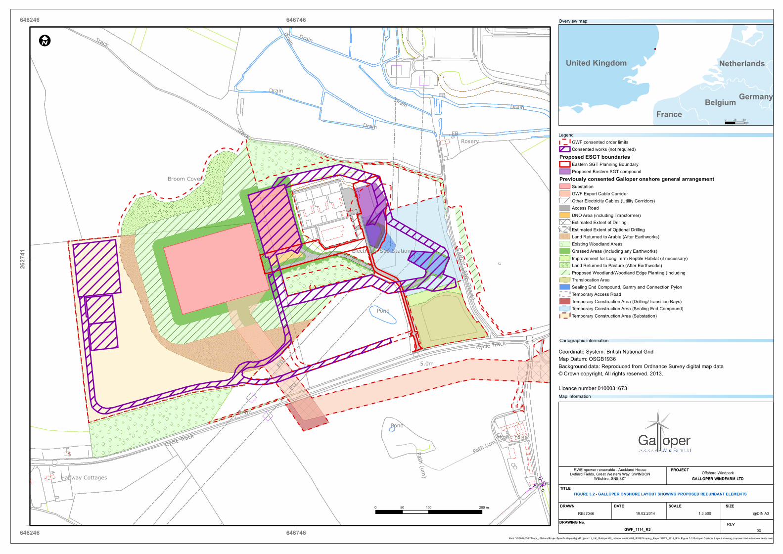
3.1.4 The ESGT will replace the requirement for the Leiston B substation which was to be constructed within Sizewell Wents woodland (Figure 3.2. The ESGT will transform the voltage and allow the electricity generated by GWF to be fed into the 400kV transmission network. The ESGT compound, at 0.57ha (including the consented sealing end compound) will be smaller than Leiston B. The original GWF scheme would have required 1.61ha of woodland to be felled to make room for the substation, cable corridors, and access road. The ESGT compound will require approximately 0.17ha of woodland to be removed – the underground cable between the GWF compound and the Leiston A substation will be laid along the consented access road and will not require any further trees to be felled.
3.2 Outline Project Description
3.2.1 As outlined in Chapter 1, Introduction, the ESGT project comprises a development of a substation compound including a Super Grid Transformer (SGT) and associated balance of plant within the GWF onshore site to the east of two existing substations.
3.2.2 Details of the project components considered for assessment are provided throughout this chapter, along with descriptive information on the methods associated with the construction, operation and decommissioning of these components. This information has been used to inform the technical chapters contained within this ES and is considered to represent the Project’s ‘development envelope’.
3.2.3 The other onshore infrastructure such as the Galloper substation will be constructed as planned and consented through the GWF DCO, with a number of exceptions which are outlined in Section 3.7. The location of the ESGT compound is described in Chapter 2, Site Description and Land Use.
3.3 Alternatives Considered
3.3.1 The ESGT is proposed as an alternative to the proposed Leiston B substation which was consented under the GWF DCO. Leiston B substation was to be constructed within the Sizewell Wents woodland and would have led to the loss of a total of 1.61ha of semi-mature woodland. Included in this figure, a cable corridor would have been required, running from the northern edge of Leiston B around the two existing substations and into the two sealing end compounds. The location of Leiston B and the associated cable corridor is shown in Figure 3.2.
3.3.2 The ESGT will only necessitate a small area of woodland to be felled (approximately 0.17ha), primarily consisting of immature trees. The compound will include the western most sealing end compound and therefore will only require a short cable corridor to connect into the Leiston substation. This will not require the removal of any woodland habitat. The proposed location of the ESGT compound is shown in Figure 1.1.
3.3.3 Underground cabling will be installed through Sizewell Wents woodland to connect the GWF substation with the Leiston A substation. The cabling will run along the consented permanent access road through the woodland and will not necessitate any further tree felling.
Galloper Wind Farm – Eastern Super Grid Transformer Project Environmental Statement – Chapter 3 Project Details Final February 2014
3.4 Onshore Substation
3.4.1 The proposed location of the ESGT compound is within an area of semi-natural grassland predominately used for grazing, located to the east of the two existing GGOWF and Leiston substations.
3.4.2 The ESGT will contain one super grid transformer (SGT) and one 400kV breaker whereas Leiston B would have contained two SGTs. Two 400kV breakers, 132 kV switchboard and associated buildings and auxiliary plant.
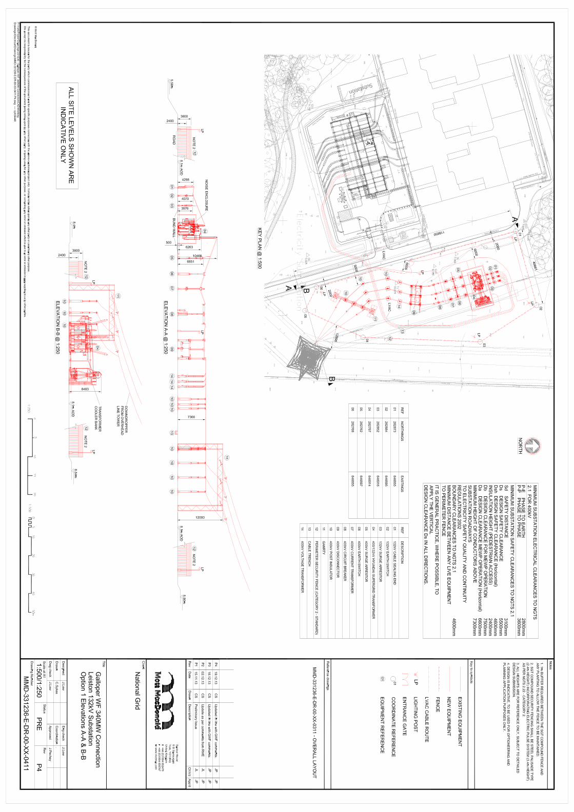
3.4.3 The SGT will be the largest single piece of plant within the ESGT compound. It will be connected to the 400kV overhead line system via a series of plant shown in Figure 3.1. The equipment to be provided in the ESGT along with the approximate heights are listed in Table 3.1 below. The equipment is listed in the order in which it will be installed in the ESGT compound, from north to south. Each item is shown in plan and elevation on Figure 3.1 .It should be noted that the layout is preliminary and will be subject to detailed design and micrositing before construction commences.
Table 3.1 Plant to be provided in the ESGT compound
Description Number required Approximate height
132kV cable sealing end 3 4.3m 132kV earth switch 3 4m 132kV surge arrestor 3 4m 400/132kV super grid transformer including cooling bank
1 6.2m
400kV surge arrestor 3 6.8 400kV earth switch 3 7.3m 400kV current transformer 3 7.3m 400kV circuit breaker 3 7.3m 400kV disconnector 3 7.3m 400kV post insulator 3 7.3m 400kV voltage transformer 3 7.3m Gantry (within consented sealing end compound)
1 12m
Note: an additional 6 post insulators will be included in the sealing end compound and were consented under the GWF DCO.
3.4.4 All of the equipment in the ESGT compound will be air insulated which means that it will be built outside and not housed in a building. The super grid transformer itself will be contained in a noise enclosure.
3.4.5 The 400/132kV super grid transformer will be protected by a bund wall which will offer containment for 110% of the volume of oil held in the transformer, compliant with The Control of Pollution (Oil Storage) (England) Regulations 2001.
3.4.6 The ESGT compound will be surrounded by an electrified fence which will be 3.6m high. The fence will be of steel palisade type with an electric pulse system mounted on top. A section drawing of the proposed fencing is included on Figure 3.1.
Galloper Wind Farm – Eastern Super Grid Transformer Project Environmental Statement – Chapter 3 Project Details Final February 2014
3.4.7 The ESGT will be accessed via the existing site access road which services the Leiston and GGOWF substation compounds. The entrance to the ESGT will be gated and an internal site access road will run along the inside of the western and northern edges of the compound. It is likely that the remainder of the compound will be finished with a gravel surface which will be suitable for service vehicles to drive over if necessary.
3.4.8 Lighting will be provided within the ESGT compound to light the entrance, access road, and key plant items. The lighting will only be used when the compound is manned e.g. during maintenance.
3.5 Items to be constructed under the DCO
3.5.1 The ESGT compound, shown in Figure 3.1, includes an area of plant which was
consented under the GWF DCO as the western most sealing end compound (work number 8A in the GWF DCO). The sealing end compound will be constructed under the DCO but will now be combined with the ESGT compound, for which planning permission is sought. The plant to be constructed within the sealing end compound under the DCO are numbers 10(400kV post insulator) and 11(Gantry, including the lines connecting to the tower) shown on Figure 3.1. The construction compound which will be used for the ESGT was also consented under the DCO and is shown in Figure 1.2.
5
4
FB
FB
ETLETL
Def
Pond
Pond
5.0m
6.4m
Drain
Track
Drain
Drain
Drain
Drain
DrainTrackRosery
Path (um)
Path (um)Home FarmCycle Track
Cycle Track
Broom Covert
Halfway Cottages
SANDY LANE (Track)
Electricity Sub Station
646246
646246
646746
646746
2627
41
I
United Kingdom
Belgium
Netherlands
FranceGermany
0 100 20050 m
Path: \\S060A0361\Maps_offshore\ProjectSpecificMaps\MajorProjects\11_UK_Galloper\06_Interconnection\02_RWE\Scoping_Report\GWF_1114_R3 - Figure 3.2 Galloper Onshore Layout showing proposed redundant elements.mxd
0 5025km
GWF consented order limitsConsented works (not required)
Proposed ESGT boundariesEastern SGT Planning BoundaryProposed Eastern SGT compound
Previously consented Galloper onshore general arrangementSubstationGWF Export Cable CorridorOther Electricity Cables (Utility Corridors)Access RoadDNO Area (including Transformer)Estimated Extent of DrillingEstimated Extent of Optional DrillingLand Returned to Arable (After Earthworks)Existing Woodland AreasGrassed Areas (Including any Earthworks)Improvement for Long Term Reptile Habitat (if necessary)Land Returned to Pasture (After Earthworks)Proposed Woodland/Woodland Edge Planting (IncludingTranslocation AreaSealing End Compound, Gantry and Connection PylonTemporary Access RoadTemporary Construction Area (Drilling/Transition Bays)Temporary Construction Area (Sealing End Compound)Temporary Construction Area (Substation)
Legend
Overview map
Coordinate System: British National GridMap Datum: OSGB1936Background data: Reproduced from Ordnance Survey digital map data© Crown copyright, All rights reserved. 2013.
Licence number 0100031673
RWE npower renewable - Auckland HouseLydiard Fields, Great Western Way, SWINDON
Wiltshire, SN5 8ZTOffshore Windpark
GALLOPER WINDFARM LTD
DRAWN DATE@DIN A3
SCALE SIZE
PROJECT
TITLEFIGURE 3.2 - GALLOPER ONSHORE LAYOUT SHOWING PROPOSED REDUNDANT ELEMENTS
1:3.50019.02.2014RE57046DRAWING No. REV
GWF_1114_R3 03
Map information
Cartographic information
Galloper Wind Farm – Eastern Super Grid Transformer Project Environmental Statement – Chapter 3 Project Details Final February 2014
3.6 Cabling
3.6.1 A High Voltage (HV) 132kV underground cable will be installed between the ESGT and the existing Leiston substation to export the electricity generated to the 400kV transmission network.
3.6.2 There will also be a need to reroute an existing underground 11kV DNO cable which runs through the ESGT compound area, as part of the ESGT works. The cable will be rerouted around the edge of the ESGT compound. A further underground cable will be installed to provide a low voltage electricity supply to the ESGT compound and run essential services such as lighting and control protection. The provision of this DNO supply requires the erection of a DNO transformer. The transformer will be connected by underground cables to the existing DNO supply located to the east of the existing GGOWF substation. The DNO transformer will be within a container of dimensions up to 3m by 3m by 3m. The remainder of the DNO area will be covered in a permeable surface or chippings to allow access to the transformer.
3.6.3 A further underground electric cable (or cables, depending on design) will be installed immediately to the north of the access road through the Sizewell Wents woodland to connect the GWF substation compound with the existing Leiston substation. This cable also forms part of the ESGT works. Works will be undertaken within the existing Leiston substation to install plant items necessary for the electrical connection from the GWF substation.
3.7 Sealing End Compound, Gantries and Overhead Lines
3.7.1 The ESGT compound will be connected to the 400kV overhead line via one of two existing towers (pylons) to the east of the existing GGOWF substation. A downlead will be installed on the western most tower, connecting to the ESGT via a sealing end compound. The 400kV transmission cable from the ESGT will be brought into the sealing end compound and connected to the overhead line via a gantry system. The sealing end compound and modifications to the arms of the pylons will be constructed under the GWF DCO. The GWF ES (GWF 2011) included the following description of the western sealing end compound:
‘The western sealing end compound will have approximate dimensions of 32m by 40m and an area of 0.22 ha. The western sealing end compound will have an approximate finished floor level of between 7.7m to 8.3m. The maximum height of founded equipment within the western sealing end compound is the top of the gantry which will have a maximum height of 13m above the floor level’.
3.8 Changes to the Galloper Wind Farm Onshore Site
3.8.1 The proposal to construct the ESGT rather than the Leiston B substation in Sizewell Wents has led to a number of other proposed changes to the onshore layout of the Galloper Wind Farm. The changes are all as a result of redesign and optimisation of the onshore layout following the decision to reduce the nominal capacity of the wind farm from 504MW to 340MW.
Galloper Wind Farm – Eastern Super Grid Transformer Project Environmental Statement – Chapter 3 Project Details Final February 2014
3.8.2 Figure 1.1 shows the layout of the DCO consented GWF onshore infrastructure. The main change is that the Leiston B substation will now not be constructed, along with the associated cabling which was to run around the northern edge of the GGOWF substation and the eastern most sealing end compound. Each of the redundant items has been highlighted in Figure 3.2.
3.8.3 The construction compounds which were proposed to the west of the onshore site will now be incorporated into areas within the main footprint and thus the haul road which would have connected them to the main site access road will also not be constructed. A 40m section immediately adjacent to the access road will be built to provide additional parking for construction traffic. All changes to the Galloper onshore site are shown in Figure 3.2.
3.8.4 The National Grid construction compound, which will be used during the construction of the ESGT, will now be located to the east of the site, adjacent to the overhead lines and approximately in the area where the eastern most sealing end compound was to be constructed. The construction compound is shown in Figure 1.2 in Chapter 1.
3.9 Project Programme
3.9.1 A period of enabling works will be undertaken prior to the construction to prepare the site for construction. The enabling works for the ESGT are expected to start in Q3 2014 and comprise the following activities:
• Removal of trees within the ESGT footprint • Removal of topsoil from ESGT footprint • ESGT platform development, consisting of site won materials • Surface treatment e.g. laying down of imported type 1 material (granular sub-
base material such as crushed concrete (actual material is dependent on sourcing and availability)) as appropriate
3.9.2 The enabling works for the ESGT compound are expected to last for approximately two
months and will be done after the enabling works for the rest of the GWF onshore site, once consent for the ESGT has been granted.
3.9.3 The main construction work for the ESGT will take around ten months and is expected to start in mid-2015. The construction works will take place at the same time as the construction works on the rest of the GWF onshore site.
3.9.4 Following construction, the commissioning phase of the ESGT construction will take approximately two weeks.
3.10 Pre-Construction Site Investigations
3.10.1 A series of intrusive ground investigations will be undertaken in the ESGT area prior to the start of the enabling works. The ground investigations are needed to determine the type of construction methods which will be used for the ESGT (e.g. piling).
Galloper Wind Farm – Eastern Super Grid Transformer Project Environmental Statement – Chapter 3 Project Details Final February 2014
3.11 Onshore Construction
Construction sequence and timing
3.11.1 The overall workforce required for the GWF onshore site and the ESGT will not exceed 200 personnel during peak construction. Working shifts are anticipated to be 07:00 to 19:00 Monday to Saturday. Construction activity may occasionally require 7 days per week. Where the working hours are expected to extend beyond those given above, these periods would be agreed in advance with SCDC. The following activities could result in an extended working week:
• Continuous concrete pours, which would generally occur nearer the start of the civil construction phase
• Sufficiently mild weather window opportunities during lengthy periods of bad weather
• Testing and commissioning of equipment Site preparation and earthworks
3.11.2 During construction, the site boundary will be securely fenced using a suitable steel mesh and panel fencing system. A construction compound will be located to the east of the two overhead lines which cross the site (see Figure 1.2). This will include contractor’s offices, cabins, and an equipment storage area. The construction compound will be fenced with timber hoarding or heras fencing, where appropriate. The construction compound will be located within an area which was designated as a temporary construction areas in the GWF ES and is consented under the DCO.
3.11.3 Earthworks will be required in order to create a level area upon which the ESGT will be built. The earthworks will be designed to balance the amount of cut and fill and to minimise the need to import or export material to and from site. Some materials, such as type 1 material, will need to be imported onto the site.
Traffic and access 3.11.4 Traffic related to the construction of the ESGT will use the main site entrance off
Sizewell Gap Road. There is sufficient space within the overall Galloper construction site for the movement and parking of the vehicles required for construction.
3.11.5 The SGT will be delivered to site via road transport as the only abnormal load required for the ESGT. The lorry is likely to be powered by two engines, one pulling the load and the other pushing. The lorry will drive into the ESGT compound where the SGT will be unloaded by crane and settled into position within the bund. The lorry will be driven out of the compound in a forwards direction by the engine which was at the rear during the SGT delivery. The predicted traffic numbers during the ESGT construction are presented in Chapter 9, Traffic and Transport.
3.12 Environmental Management during Construction
3.12.1 The construction of the ESGT will be undertaken in accordance with the GWF Construction Code of Practice (CCoP) which has been agreed SCDC (Appendix 3.1). Applicable environmental measures in the CCoP are:
Galloper Wind Farm – Eastern Super Grid Transformer Project Environmental Statement – Chapter 3 Project Details Final February 2014
• Dust: Damping down surfaces during dry and windy weather using water bowsers; limiting of road speeds on site, avoidance of unnecessary idling of engines; road sweepers to clean mud and other deposited material from the public highway will be utilised, as necessary, to suppress dust and to reduce hazards to public road users
• Noise and vibration: use of silenced equipment as far as possible, ensuring plant machinery is turned off when not in use; avoidance of unnecessary idling of vehicle engines; ensuring no music or radios are played onsite.
• Construction activities will be monitored and policed by suitable qualified specialists such as an Environmental Clerk of Works supported by other specialists as necessary (e.g. ecological watching briefs, auditors).
3.13 Commissioning
3.13.1 National Grid will be responsible for commissioning of the ESGT which will take place once construction is complete and before operation begins. In general, commissioning will comprise the following stages:
• A mechanical, visual and electrical continuity assessment • An energisation programme • Testing mechanical, electrical and control functions • Identification of faults • Rectification of faults • Re-testing and • Certification
3.14 Substation Overview
Operation and maintenance 3.14.1 All elements within the ESGT will be designed to be operated unmanned 24 hours a
day. Regular maintenance and inspection visits will occur to ensure the plant is kept in good condition. Best practice guidelines for the frequency of maintenance of this equipment is summarised in Table 3.2 and would be adhered to throughout the operational phase.
Table 3.2 Maintenance Required at ESGT Equipment Maintenance frequency Type of work Transformer Routine – annually
Intermediate – four years Major – 12 years
• Check silica gel and ventilator, check for oil leakage, check cooling equipment, general visual inspection
• Test for water content, dielectric strength, acidity, and dissolved gas analysis
• Clean brushing and grease ventilator Air Insulated (AIS) switchgear
Routine – annually Intermediate – six years
• Check gas pressure, check and clean mechanisms and hydraulics
• Test protection and control equipment
3.14.2 It is envisaged that the maintenance works will normally only require a site visit by a light goods vehicle. Any major equipment failure necessitating removal will require the use of suitable mobile cranes.
Galloper Wind Farm – Eastern Super Grid Transformer Project Environmental Statement – Chapter 3 Project Details Final February 2014
Utilities and environmental issues 3.14.3 Surface water from within the ESGT compound will discharge into a new site drain
which will be fitted with an oil water separator with penstock valve and sampling chamber.
3.14.4 Surface water quality will be protected from pollution sources by the following measures:
• Oil retention bunds around (and in some cases below) the transformers, reactors and any other oil filled equipment that may be used; and
• Oil interceptors on the surface water drainage gullies.
3.14.5 Transformers and associated cooling equipment will comply with NGET noise level specifications measured in accordance with IEC 60076-10. Noise impacts are considered within Chapter 6, Noise.
3.14.6 It is not envisaged that the site will be provided with permanent lighting around the internal roads or equipment. Lighting may be provided at the main entrance to the compound for safe ingress / egress. In the event of any essential works, temporary task lighting may be provided by the maintenance staff in addition to any installed lighting use.
3.15 Decommissioning
3.15.1 During the decommissioning of the ESGT, all above surface equipment and structures will be removed from site. Concrete foundations and chippings will be removed to a depth of 1m. The site will then be restored through natural regeneration.
3.15.2 It is likely that the decommissioning of the ESGT will be undertaken at the same time as the overall decommissioning of the Galloper onshore site.
3.16 Local Community Relations
3.16.1 RWE and SSE have established links with the community surrounding the Galloper Wind Farm and ESGT site due to the presence of GGOWF. During the ESGT construction works and the subsequent operation of the ESGT, GWF will continue to maintain these links and will ensure that the local community is kept informed about activities on the site. It is anticipated that this will be done mainly via community newsletters distributed in the locality, via the project noticeboard located at Sizewell beach, and through the Local Liaison Committee (LLC), the first meeting of which was held in October 2013.
3.17 References
Galloper Wind Farm (2011). Galloper Wind Farm Project 2011 Environmental Statement