usability of gnss technique for cadastral surveying
TRANSCRIPT
Proceedings of the World Cadastre Summit 2015, Istanbul
266 | P a g e
USABILITY OF GNSS TECHNIQUE FOR CADASTRAL SURVEYING
Reha Metin Alkan 1, 2, İ. Murat Ozulu 1, Veli İlçi 1 , F. Engin Tombuş 1,
Murat Şahin 1
¹ Hitit University, North Campus, 19030, Çorum, Turkey [email protected], [email protected], [email protected],
[email protected], [email protected] ² Istanbul Technical University, Maslak, 34469, Istanbul, Turkey
ABSTRACT Cadastral surveys are conducted by General Directorate of Land Registry and Cadastre of Turkey (GDLRC), which dates back to 1847 in Turkey. Over the past several years, 99% of first facility cadastral study has been done. However, the necessity of largely renovation study has showed up owing to new technologies, new requirements and other factors. Regeneration of the portion of the works, especially for the maps made with very old traditional methods, have become essential due to the failures of those in terms of accuracy and technical inadequateness in the present conditions. When it is considered that almost everything is integrated with each other in our global world, measurements made in a seamless datum is not a great option but a necessity. In addition, one of the issues which should be taken into account is that all study should be conducted as fast as possible. When all these issues are considered, the most important concern in determining the position is seemed to be realized by satellite-based positioning systems today. This study focuses on the use of satellite-based positioning systems and issues that should be considered in cadastral surveying. Key words: Cadastral Survey, Cadastre, GNSS, CORS INTRODUCTION The population of the world, which increases rapidly at an average rate of % 1.2 annually, has exceeded 7 billion. However, despite the increase in population, 150,000,000 km² terrestrial area, which composes the % 29.2 of the surface of the earth, has not changed significantly. When this is taken into account, it is clear that the leading precious fact is land. Considering that not all of these areas are suitable for the life and use of human being, it is obvious that land and soil should be used with care and managed in accordance with professional policies. What is undoubtedly essential to do in this regard is to identify the overall aspects of this value and keep records with the use of information systems. In this context, information about the ownership and boundary of a real property is specified with cadastral surveying. When the fact is not only the civilian but also boundary conflicts of many countries, resulting serious legal problems and even wars among countries, the significance of the issue can easily be understood.
http://wcadastre.org
267 | P a g e
In Turkey, Cadastral surveys are conducted by General Directorate of Land Registry and Cadastre of Turkey (GDLRC). When Turkey Republic was established, cadastral studies were enacted in accordance with the 658 numbered Cadastre Law in 1925. Cadastral studies are still conducted with regard to 3402 numbered law in Turkey (İnam et al., 2011). The current status of the Turkey Cadastre is given in Table 1 (URL-1).
Table 1. Status of Turkey Cadastre Realization
Total Units (District&Villag)e
Realization problemtic units (*) before 2003 between 2003-2015 on-going
52,054 38,803 12,758 193 300
(*) Forest, Border Disputes etc. Regarding this data, it can be concluded that, 99% of the cadastral studies have been completed. Although the first facility cadastre is about to be completed in Turkey, Cadastre Renovating/Updating studies are in progress because of the following main reasons (Çağla et al., 2011; Meha et al., 2013):
- Cadastral reconstruction, - Technical inadequateness, - Loss of application quality, - Lack of information, - Showing the boundaries of the ground as its original, - Land consolidation in urban and rural areas, - Regular maintenance of cadastre.
Turkish government aims at improving the cadastral system to maintain it in a more appropriate, effective and contemporary manner (Çete, 2010). According to a study carried out by the GDLRC of Turkey in 2008, throughout the country under the Cadastre Law Article 22-a (Renovation Cadastre) that needed to renew approximately 8,100,000 parcels has been determined. A total of 5,642,255 parcels were auctioned by the World Bank and the GDLRC’s their own budget between 2009 and 2014, and studies were completed in 3,600,000 parcels (URL-2). This means that about 44% of the parcels have been completed, and it is evident that a lot of studies would be done in this scope. It is generally said that there are plenty of studies in such fields as follows:
- Cadastre renovating/updating studies, - Setting marks of parcels, - The works carried out within the scope of land use conversion and amalgamation
(measuring the buildings and other details on the parcel), - Controlling maps and plans registered, - Forest cadastre, - Boundary dispute and novation, - 3D cadastral mapping.
Proceedings of the World Cadastre Summit 2015, Istanbul
268 | P a g e
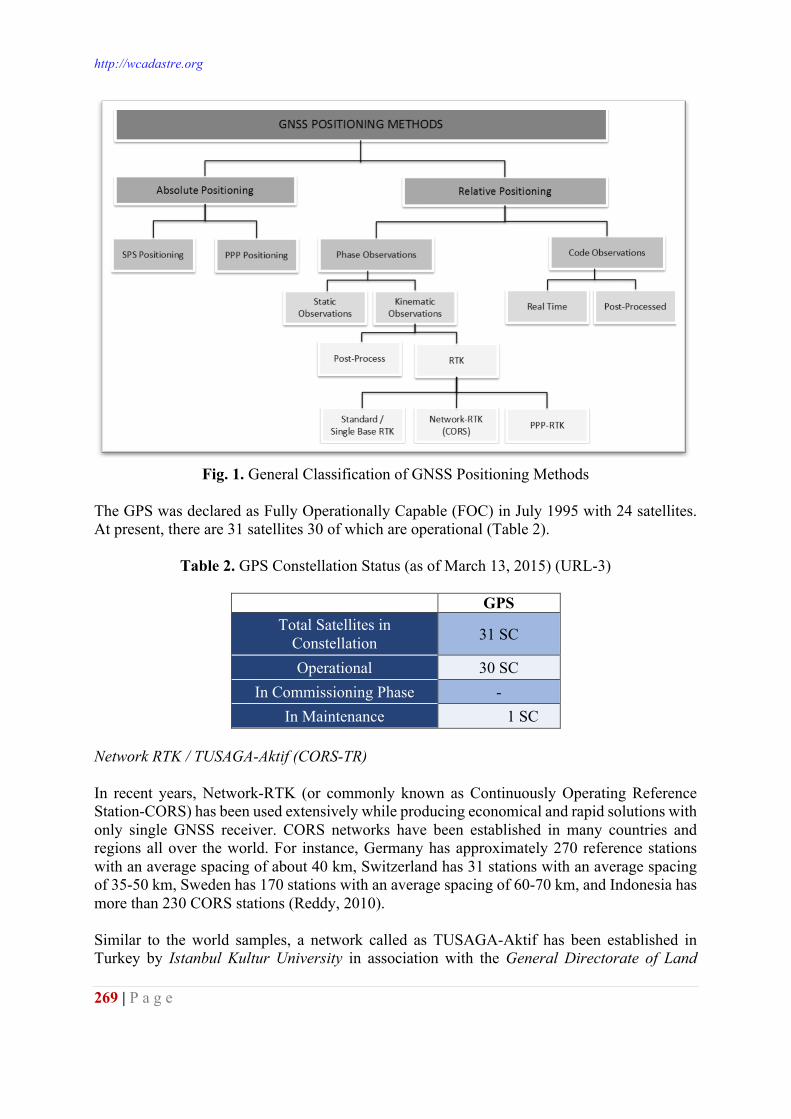
Historical background, current situation and emerging main problems of cadastral studies in Turkey can be found in detail in Çete, (2010); İnam et al., (2011) and URL-2. All these study have been carried out either by related Official Cadastral Units or Licensed Surveyors. In those studies, cadastral surveys have been conducted with the use of conventional terrestrial methods/equipment; i.e. steel band, EDM, theodolite and for a couple of decades total stations and etc. Nevertheless, Global Navigation Satellite System (GNSS) (especially GPS and GLONASS), which have many advantages over conventional methods, have begun to be widely used all around the world. GNSS systems are competing with conventional methods in almost all fields of surveying applications including cadastral surveying. Although the GNSS systems have considerably facilitated the measurements, there are still some limitations in their usability in some cases like in densely urban areas, mountains, heavy tree cover, ravines and similar places. Even though the combination of GPS and secondary satellite system like GLONASS observations can overcome the abovementioned problems, conventional surveying techniques are still required in some instances. A REVIEW of GLOBAL NAVIGATION SATELLITE SYSTEM The term GNSS is now used to describe a many different satellite positioning systems operated by different countries. Among them, GPS (Global Positioning System) is the very well-known and widely used one while the others, i.e. GLONASS, Galileo etc. have started to be used or about to be used in the near future. 20 years ago, the usage of the GNSS by civilian was mainly limited to merchant ship crews and surveyors, but today there are millions of receivers which are used to achieve different tasks. Moreover, GNSS technology is becoming the most effective positioning methods for all types of engineering projects (Bonnor, 2012). GNSS is competing with traditional surveying techniques and has widely used for marine, air and land applications for achieving navigation, surveying and scientific purposes because of the advantages such as being almost independent of weather conditions, not requiring surveying points seeing each other, being able to manage surveying during the day&night, and etc. The systems that constitute the GNSS are briefly given in the following sections. GPS GPS is a satellite-based radio navigation system which was maintained by the United States Department of Defense. Although it was originally designed as a military system, it has become a global utility primarily used as a navigation system and its civil applications have grown much faster. The system provides position, velocity and time anywhere in the world. Since the launch of the first operational GPS satellite in 1978, as of today, the GPS has been widely used in marine, air and land applications. Positioning with GPS can be realized in two main ways: i-absolute positioning, ii- relative positioning. A general classification of the GPS positioning methods are shown in Fig. 1 (Kahveci and Yıldız, 2012).
http://wcadastre.org
269 | P a g e
Fig. 1. General Classification of GNSS Positioning Methods
The GPS was declared as Fully Operationally Capable (FOC) in July 1995 with 24 satellites. At present, there are 31 satellites 30 of which are operational (Table 2).
Table 2. GPS Constellation Status (as of March 13, 2015) (URL-3)
GPS Total Satellites in
Constellation 31 SC
Operational 30 SC In Commissioning Phase -
In Maintenance 1 SC Network RTK / TUSAGA-Aktif (CORS-TR) In recent years, Network-RTK (or commonly known as Continuously Operating Reference Station-CORS) has been used extensively while producing economical and rapid solutions with only single GNSS receiver. CORS networks have been established in many countries and regions all over the world. For instance, Germany has approximately 270 reference stations with an average spacing of about 40 km, Switzerland has 31 stations with an average spacing of 35-50 km, Sweden has 170 stations with an average spacing of 60-70 km, and Indonesia has more than 230 CORS stations (Reddy, 2010). Similar to the world samples, a network called as TUSAGA-Aktif has been established in Turkey by Istanbul Kultur University in association with the General Directorate of Land
Proceedings of the World Cadastre Summit 2015, Istanbul
270 | P a g e
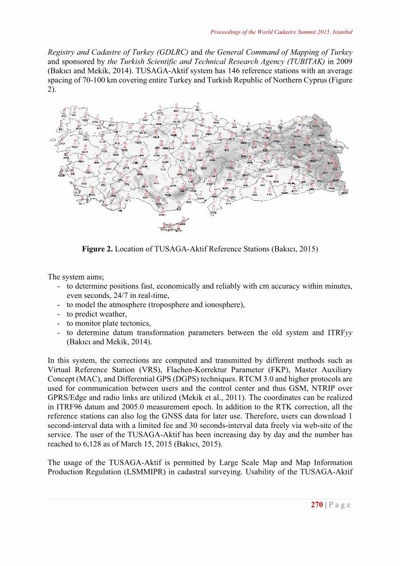
Registry and Cadastre of Turkey (GDLRC) and the General Command of Mapping of Turkey and sponsored by the Turkish Scientific and Technical Research Agency (TUBITAK) in 2009 (Bakıcı and Mekik, 2014). TUSAGA-Aktif system has 146 reference stations with an average spacing of 70-100 km covering entire Turkey and Turkish Republic of Northern Cyprus (Figure 2).
Figure 2. Location of TUSAGA-Aktif Reference Stations (Bakıcı, 2015)
The system aims;
- to determine positions fast, economically and reliably with cm accuracy within minutes, even seconds, 24/7 in real-time,
- to model the atmosphere (troposphere and ionosphere), - to predict weather, - to monitor plate tectonics, - to determine datum transformation parameters between the old system and ITRFyy
(Bakıcı and Mekik, 2014). In this system, the corrections are computed and transmitted by different methods such as Virtual Reference Station (VRS), Flachen-Korrektur Parameter (FKP), Master Auxiliary Concept (MAC), and Differential GPS (DGPS) techniques. RTCM 3.0 and higher protocols are used for communication between users and the control center and thus GSM, NTRIP over GPRS/Edge and radio links are utilized (Mekik et al., 2011). The coordinates can be realized in ITRF96 datum and 2005.0 measurement epoch. In addition to the RTK correction, all the reference stations can also log the GNSS data for later use. Therefore, users can download 1 second-interval data with a limited fee and 30 seconds-interval data freely via web-site of the service. The user of the TUSAGA-Aktif has been increasing day by day and the number has reached to 6,128 as of March 15, 2015 (Bakıcı, 2015). The usage of the TUSAGA-Aktif is permitted by Large Scale Map and Map Information Production Regulation (LSMMIPR) in cadastral surveying. Usability of the TUSAGA-Aktif
http://wcadastre.org
271 | P a g e
for cadastral surveying not only provides greater speed but also requires less time, less money and fewer personnel. GLONASS The Russian Federation operates their own satellite-based system called as GLObal’naya NAvigatsionnaya Sputnikovaya Sistema (GLONASS) and it was developed primarily for the use of the Soviet military. Development of the system began in 1976, but the first satellite was launched in October 1982 and 10 more satellites were launched between 1982 and 1985 (Bonnor, 2012). Due to the financial recession in Russian Federation, GLONASS system continued to work with too few satellites in 1980s and 1990s. In 2000, after the economic recession period, Russian government made a considerable investment to reconstruct the GLONASS satellite system. The system was made fully available for civilian in 2007. In 2010, GLONASS achieved 100% coverage of Russia’s territory. Full Operational Capability (FOC) and thus full global coverage for GLONASS were attained with 24 satellites in 2011. As of today, GLONASS system has 28 satellites 24 of which are operational (Table 3).
Table 3. GLONASS Constellation Status (as of March 13, 2015) (URL-4)
GLONASS Total Satellites in
Constellation 28 SC
Operational 24 SC In Commissioning Phase -
In Maintenance - Galileo European Commission decided to develop the Europe’s own global navigation satellite system named as Galileo. Unlike GPS and GLONASS, construction and operation of Galileo will be under the control of civilians. Galileo was designed to cooperate with GPS and GLONASS. The full operational capability constellation of Galileo will consist of 30 satellites (27 operational + 3 active spares). These 30 satellites will revolve around the world in three circular Medium Earth Orbit (MEO) planes and at an inclination of the orbital planes of 56 degrees to the equator. On 21 October 2011 a Soyuz rocket from French Guiana launched two satellites, with two more following on 12 October 2012. The Galileo In-Orbit Validation (IOV) test campaign was conducted in 2013. The test tes shown that, deployed four Galileo satellites and ground infrstructure work very well. They will be followed by several launches with Ariane-5 or Soyuz from the Europe’s Space Port in French Guiana (URL-5; URL-6). BeiDou (BDS) BeiDou Navigation Satellite System (BDS) is the global navigation satellite system which has been established and operated independently by China. The system was planned to establish as three steps: demonstrational system, regional system and global system. The regional system is in full operation comprising 5 Geostationary Earth Orbit (GEO) satellites, 5 Inclined Geosynchronous Earth Orbit (IGSO) satellites and 4 Medium Earth Orbit (MEO) satellites. The
Proceedings of the World Cadastre Summit 2015, Istanbul
272 | P a g e
system gives two types of service to their users as standard positioning service which is free for all civilian users and precise positioning service & system-embedded wide area differential positioning are only for authorized users (Xu et al., 2014). In 2020, the BeiDou will provide high accuracy and high reliability positioning to GNSS users in any time and all-weather conditions in global coverage (Li et al., 2014). Japan Quasi-Zenith Satellite System (QZSS) Japan is planning a Quasi-Zenith Satellite System (QZSS) using three satellites. In March 2013, Japan’s Cabinet Office announced the expansion of the QZSS from three satellites to four. The plan was to have four satellites constellation in 2018. The system will include three satellites in the Inclined Geosynchronous Earth Orbit (IGSO) and one satellite in the Geostationary Earth Orbit (GEO) (Montenbruck et al., 2014). The first satellite (named as Michibiki) was launched in September 2010. At present, only one QZSS satellite is in operation. High elliptical orbits (more than 70 degree) increase the reliability of the satellites in service area more than 12 hours a day (Bonnor, 2012). Therefore, users can receive the signals with high elevation angle from at least one of the satellites of QZSS. Moreover, Japan and USA have agreed that GPS and QZSS have complete compatibility and interoperability of the systems. With small modifications of the GPS receiver, users can receive QZSS signal and calculate their position combining the GPS signals (Kogure et al., 2006). GAGAN and IRNSS India’s satellite system is named GPS Aided GEO Augmented Navigation (GAGAN). The first GAGAN communication satellite was launched on 21 May 2011. The aim of the system is not only navigation but also communication and some other purposes. The Indian Regional Navigational Satellite System (IRNSS), which is an autonomous regional satellite navigation system, was approved by the Indian government in May 2006 to provide accurate position information in Indian region. The first IRNSS satellite was launched in July 2013. Four Inclined Geosynchronous Earth Orbit (IGSO) and three Geostationary Earth Orbit (GEO) satellites were planned to be launched so that all satellites were visible in Indian Region (Majithiya et al., 2011). The entire IRNSS constellation of seven satellites is planned to be completed by 2015. IRNSS will provide two types of services; one is the Standard Positioning Services (SPS) available for all users and the other is Restricted Services (RS), available for authorized users. Deployment status of global and regional satellite positioning systems are summarized in Table 4 (Montenbruck et al., 2014). A total of 6 satellite-based positioning systems that operated by different countries, i.e. GPS, GLONASS, Galileo, BeiDou (BDS), QZSS, and GAGAN&IRNSS, have become available for different type of users all over the world. The abovementioned systems will work together and will be compatible, interoperable and interchangeable among each other. This obviously increases the availability and the coverage while providing more robust and reliable services. The combined system provides more accurate positioning in some locations that have marginal sky visibility like urban canyons, mountains, heavy tree cover, ravines, open-pit mines and
http://wcadastre.org
273 | P a g e
extreme marine environments where satellite signals may either be blocked or strongly degraded by obstacles (Tamrakar, 2013).
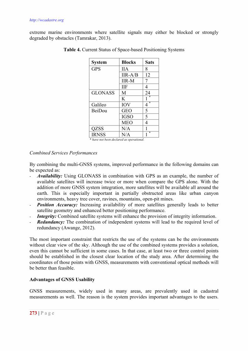
Table 4. Current Status of Space-based Positioning Systems
System Blocks Sats GPS IIA 8
IIR-A/B 12 IIR-M 7 IIF 4
GLONASS M 24 K 1 *
Galileo IOV 4 * BeiDou GEO 5
IGSO 5 MEO 4
QZSS N/A 1 IRNSS N/A 1 *
* have not been declared as operational. Combined Services Performances By combining the multi-GNSS systems, improved performance in the following domains can be expected as: - Availability: Using GLONASS in combination with GPS as an example, the number of
available satellites will increase twice or more when compare the GPS alone. With the addition of more GNSS system integration, more satellites will be available all around the earth. This is especially important in partially obstructed areas like urban canyon environments, heavy tree cover, ravines, mountains, open-pit mines.
- Position Accuracy: Increasing availability of more satellites generally leads to better satellite geometry and enhanced better positioning performance.
- Integrity: Combined satellite systems will enhance the provision of integrity information. - Redundancy: The combination of independent systems will lead to the required level of
redundancy (Awange, 2012). The most important constraint that restricts the use of the systems can be the environments without clear view of the sky. Although the use of the combined systems provides a solution, even this cannot be sufficient in some cases. In that case, at least two or three control points should be established in the closest clear location of the study area. After determining the coordinates of those points with GNSS, measurements with conventional optical methods will be better than feasible. Advantages of GNSS Usability GNSS measurements, widely used in many areas, are prevalently used in cadastral measurements as well. The reason is the system provides important advantages to the users.
Proceedings of the World Cadastre Summit 2015, Istanbul
274 | P a g e
Some of the advantages of GNSS surveying with respect to conventional methods in cadastral survey is given below (Tamrakar, 2013). - Inter-visibility between consequent stations are not required, - Traverse stages in the field for providing control points for classic surveys are not needed, - Establishment of the control points is more accurate, easier with less cost, - The measurements can be made in day time and at night, under almost all weather conditions, - Simple field operation, - Continuous 3D positioning, - All coordinates can be estimated in a global datum, i.e. ITRFyy or so on. The abovementioned features make GNSS quite attractive for survey works. Some Recommendation for GNSS Usability Some recommendation as a minimum standard for the surveyors using GNSS is given below (Tamrakar, 2013; URL-7; URL-8); - GNSS surveyors should be trained before using this technique in cadastral surveys, - As GNSS signals and fixed solutions can be affected from cell tower, radio station, and high-
voltage transmission line, to establish geodetic control points must not be selected in the areas where they degrade GNSS signal quality,
- Reflecting surface like metal roofing, big vehicles and large water surface in surveying area may cause multipath error. Thus, it is suggested not to choose these kind of places,
- The location of the points must be well located in terms of ground stability, accessibility, clear sky views, protection from vandalism and disturbance,
- Although it is not necessary for the control points, the points should be intervisible for ease of subsequent use by conventional techniques,
- A proper observation log must be filled up, - GNSS station obstruction diagram should be drawn carefully (obstructions and their
elevation angle is shown), - GNSS results can be affected by meteorological changes notably due to longer distance, thus
instantly changing weather conditions must be written down in observation logs, - GNSS receiver and antenna used in the survey should be of geodetic or survey grade
equipment, - GNSS measurement equipment should be calibrated and standardized periodically before
used in the field, - The measurements should be carried out by considering the accuracy criteria
accepted/recommended by the official authority/related regulation(s), - The appropriate equipment and methods should be the choice to be able to meet the required
accuracy, - Zero baseline test should be conducted for a pair of GNSS receivers to verify the precision
of the receiver, to prove that the receiver is operating correctly and to validate the data processing software,
- GNSS antenna height must be measured once before and after each survey, - If possible, the GNSS surveys are conducted during the periods when the maximum number
of satellites is in view, and the value of PDOP is at its minimum, - The GNSS surveys should be observed with enough time to remove large outliers and to fix
the reliable solutions,
http://wcadastre.org
275 | P a g e
- At least two independent observations (two baselines) should be carried out, - Independent observations should be carried out after 30 minutes elapses (this allows the
satellite constellation to change) by changing the height of the antenna (with cold start), - Minimum 2 minutes observation is recommended for RTK and CORS RTK users, - CORS RTK surveyors should use the nearest CORS base station for single-base users. Whether conventional or GNSS system is used to get the required accuracy of the survey, the surveyor should understand and be aware of the following issues (URL-9); - The limitation of the equipment to be used, - The observation procedures, - Processing techniques, - Statistical analysis. USABILITY of GNSS TECHNIQUE for CADASTRAL SURVEYING in TURKEY Cadastral surveys have been carried out with different methods using various type of instruments with a compass and steel tape and then prism, tachometer, reduction tachometer, electromagnetic measurement instruments and more recently total station (Çağla, et al., 2011). The rapid change in the world of science and technology has closely affected our profession and has started to use satellite-based positioning systems, especially GPS and GLONASS. All the standards must be adapted to the government agency in Turkey with regard to map and map information production. Those standards were enacted in Large Scale Map and Map Information Production Regulation (LSMMIPR) accepted in 2005. According to these regulations, cadastral measurements can be conducted with GNNS systems (in some situation conjunction with conventional terrestrial methods). In case of using the GNSS methods, the measurements should be conducted by considering the criteria given in the Regulation. Some measurement and accuracy criteria recommended by the LSMMIPR is given in Table 5 (URL-10). CONCLUSIONS In this study after explaining cadastre’s current situation in Turkey briefly, it has been explained that areas of study and issues of study should be carried out in Turkey. As explained in the study, although 99 % of cadastral surveys were completed in Turkey, there are still a lot of studies that will be carried out (like especially renovation, regular maintenance of cadastre, and etc.). Even if optical methods can be still used, GNSS systems have become essential tools for cadastral surveyors thanks to their many advantages. Thus, indeed, it is widely used by providing flexibility and offering cost effective solutions around the world. By utilizing the type of CORS networks, positioning with high accuracy and in short time routinely is conducted in Turkey and across the world. In summary if to say; - The cadastral maps which constitute the basis for property right as one of the most
fundamental human rights should be meticulously conducted by expert surveyors. Surveys carried out by unqualified technical staff will cause difficult and even irremediable problems,
Proceedings of the World Cadastre Summit 2015, Istanbul
276 | P a g e
- Training the users of this technology is extremely important. Those who carry out such measurements should be aware that they also produce important information. Thus, cadastral practitioners should be well trained and educated in the use of GNSS systems,
- Some control mechanism should be established and conducted in the field in addition to the ones that are already carried out in conventional methods,
- It is mostly possible to get a result even under the quite large DOP values, in poor satellite configuration and in multipath environment. Coordinate information by looking at the results cannot solve a problem without taking these factors into account. Furthermore, it could bring about new problems.
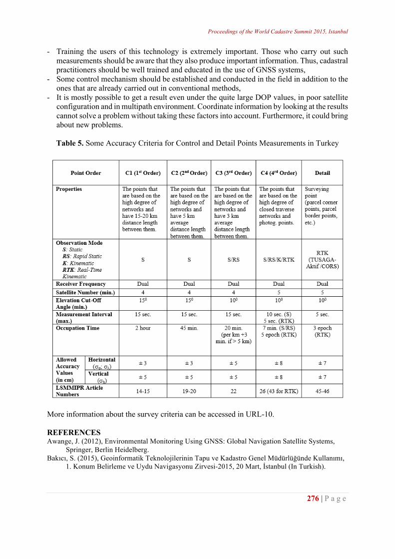
Table 5. Some Accuracy Criteria for Control and Detail Points Measurements in Turkey
More information about the survey criteria can be accessed in URL-10. REFERENCES Awange, J. (2012), Environmental Monitoring Using GNSS: Global Navigation Satellite Systems,
Springer, Berlin Heidelberg. Bakıcı, S. (2015), Geoinformatik Teknolojilerinin Tapu ve Kadastro Genel Müdürlüğünde Kullanımı,
1. Konum Belirleme ve Uydu Navigasyonu Zirvesi-2015, 20 Mart, İstanbul (In Turkish).
http://wcadastre.org
277 | P a g e
Bakıcı, S. and Mekik, Ç. (2014), TUSAGA-Aktif: Delivering Benefits to Turkey, Coordinates, X (02), pp.19-26.
Bonnor, N. (2012), A Brief History of Global Navigation Satellite Systems, The Journal of Navigation, 65 (1), pp.1-14.
Çağla, H., Akkus, S., Civcik, E., and Ozugur, İ. (2011), Konya Example of Cadastre Renovation Work in Turkey, FIG Working Week 2011, 18-22 May 2011, Marrakech-Morocco.
Çete, M. (2010), The Recent Reforms in the Turkish Cadastre, FIG Congress 2010, 11-16 April, Sydney, Australia.
İnam, Ş., Ertaş, M., Yalpır, Ş., Başarır, A., and Akca, M. (2011), Renovation Studies in Turkey Cadastre: Reasons and Project Results, FIG Working Week 2011, 18-22 May 2011, Marrakech-Morocco.
Kahveci, M. ve Yıldız, F. (2012), GPS/GNSS Uydularla Konum Belirleme Sistemleri Teori ve Uygulama. (Güncellenmiş 5. Basım), Ankara: Nobel Yayınevi (In Turkish).
Kogure, S., Sawabe, M., and Kishimoto, M. (2006), Status of QZSS Navigation System in Japan, Proceedings of the 19th International Technical Meeting of the Satellite Division of The Institute of Navigation (ION GNSS 2006), Fort Worth, TX, September 2006, pp. 2092-2102.
Li, M., Qu, L., Zhao, Q., Guo, J., Su, X., and Li, X. (2014), Precise Point Positioning with the BeiDou Navigation Satellite System, Sensors, 14(1), pp.927-943.
Majithiya, P., Khatri, K., and Hota, J.K. (2011), Indian Regional Navigation Satellite System - Correction Parameters for Timing Group Delays, InsideGNSS, 6(1), pp.40-46.
Meha, M., Kadiri, Q., Çaka, M., Murati, R., Ahmeti, A., Shaqiri, B., Kelmendi, F., Sinani, Q., Xani, E., and Ahmetaj, K. (2013), Catalogue for Measuring and Creating Cadastral Units, Kosovo Cadastral Agency.
Mekik, Ç., Yıldırım, O., and Bakıcı, S. (2011), The Turkish Real Time Kinematic GPS Network (TUSAGA-Aktif) Infrastructure, Scientific Research and Essays, 6(19), pp. 3986-3999.
Montenbruck, O., Steigenberger, P., Khachikyan, R., Weber, G., Langley, R.B., Mervart, L., and Hugentobler, U. (2014), IGS-MGEX: Preparing the Ground for Multi-Constellation GNSS Science, InsideGNSS, No. 1/2, pp.42-49.
Reddy, J. (2010), The Integration of CORS Networks and the Cadastre and its Application in NSW, Australia, FIG Congress 2010, 11-16 April, Sydney, Australia.
Tamrakar, R.M. (2013), Potential Use of GPS Technology for Cadastral Surveys in Nepal, Nepalese Journal of Geoinformatics, Vol 12, pp.33-40.
Xu, A., Xu, Z., Xu, X., Zhu, H., Sui, X., and Sun, H. (2014), Precise Point Positioning Using the Regional BeiDou Navigation Satellite Constellation, Journal of Navigation, 67(3), pp. 523-537.
URL-1: The Current Status of the Turkey Cadastral Studies (In Turkish). Available from: http://www.e-tkbm.gov.tr/publisher/projeizleme.htm [accessed 13/03/2015]. URL-2: TKGM 2014 Yılı Performans Programı (In Turkish). Available from: http://www.tkgm.gov.tr/sites/default/files/icerik/ekleri/tkgm-
performans_programi_tasari-2014.pdf [accessed 13/03/2015]. URL-3: GPS Constellation Status. Available from: http://www.glonass-center.ru/en/GPS/ [accessed 13/03/2015]. URL-4: GLONASS Constellation Status. Available from: http://www.glonass-center.ru/en/GLONASS [accessed 13/03/2015]. URL-5: Galileo. Available from: http://www.gsa.europa.eu/galileo/why-galileo [accessed 13/03/2015]. URL-6: Galileo. Available from: http://www.esa.int/Our_Activities/Navigation/The_future_-_Galileo/What_is_Galileo
[accessed 13/03/2015]. URL-7: Singapore Land Authority - Guidelines and Specifications for GPS Surveys of ISN Markers
(Version 2.4), Mar 2011.
Proceedings of the World Cadastre Summit 2015, Istanbul
278 | P a g e
Available from: http://www.sla.gov.sg/Portals/0/Circulars/att/LS/csdsgsd/Guidelines_and_Specifications_for_GPS_Surveys_of_ISN__Markers_v4.PDF [accessed 13/03/2015].
URL-8: New South Wales Government - Surveyor General’s Directions No. 9, GNSS for Cadastral Surveys, May 2014.
Available from: http://www.lpi.nsw.gov.au/__data/assets/pdf_file/0006/25944/sgddir9_Ver2.5_May_2014.pdf
[accessed 13/03/2015]. URL-9: Guidelines for Cadastral Surveying using Global Navigation Satellite Systems (GNSS),
NIMA (National Imagery and Mapping Agency), 2003. Available from: http://www.sssi.org.au/userfiles/docs/QLD
Region/documents_1342665635458677117.pdf [accessed 13/03/2015]. URL-10: Large Scale Map and Map Information Production Regulation (In Turkish). Available from: http://www.resmigazete.gov.tr/eskiler/2005/07/20050715-5.htm [accessed 13/03/2015].
http://wcadastre.org
279 | P a g e
TESTING CORS SYSTEM FOR CADASTRAL SURVEYING
Nursu Tunalioğlu¹, Atınç Pirti²
¹,² Department of Geomatic Engineering, Yildiz Technical University, Campus of Davutpaşa, 34321 İstanbul, Turkey - [email protected]; [email protected]
ABSTRACT CORS surveys with GNSS have been used for a variety of different surveying applications. Surveyors, GIS users, engineers, scientists, and the public at large that collect GNSS data can use CORS data to improve the precision of their positions. CORS enhanced post-processed coordinates approach a few centimeters relative to the Reference System, both horizontally and vertically. A network of Continuously Operating Reference Stations (CORS) that provide Global Navigation Satellite System (GNSS) data consisting of carrier phase and code range measurements in support of three dimensional positioning, meteorology, space weather, and geophysical applications. Its use for cadastral work is becoming commonplace. A case study was conducted to investigate the use of the CORS technique for boundary surveys. For this purpose, measurements were performed in the city of İstanbul, Turkey. Fourteen points were selected in both normal and difficult measurement conditions in the project area. The analyses were made in three steps. In the first step, the CORS results obtained on different periods were compared with each other; in the second, the total station observations have been realized on site to assign as fixed coordinates in evaluations; in the last step, the CORS measurement results were compared with those of the total station. The results showed differences of up to centimeters between the coordinates derived from the two survey methods in the obstructed areas. We conclude that the CORS technique competes well with the traditional survey methods in terms of accuracy except in obstructed areas.
Key words: CORS, Boundary, Cadastral Surveying, Accuracy INTRODUCTION
Cadastral survey is the discipline of land surveying that deals with either geometrical definition of the boundary property or legal assignment and/or registration of landowner, and which manages and arranges this relationship based on laws. There have been various techniques used for cadastral surveying such as digital cadaster using total stations and Global Positioning Systems (GPS) instruments, digital aerial photogrammetry, and cadastral mapping using high-resolution satellite images [1]. Cadastral maps produced by cadastral surveys are fundamental requirement to enhance a sustainable and justified determination and arrangement on land properties regarding owner rights. With continual research and development into GPS/GNSS systems, the techniques and systems have become more reliable, cheaper and more productive, which brings the GNSS more attractive for variety of surveying solutions [2]. GPS/GNSS based survey for point positioning has become a fundamental survey technique for all kind of engineering and related survey issues. Furthermore, the advantages of the technique and the recent developments regarding
Proceedings of the World Cadastre Summit 2015, Istanbul
280 | P a g e
positioning have been issued to different disciple studies as well. The usage areas of GPS/GNSS system have been widened due to technological developments and methodological enhancements that have been met in recent years. Among the various types of surveys, particularly cadastral survey, GPS/GNSS based surveying method has found significant importance in terms of accurate positioning, easy to apply, less labor on site. CORS surveys with GNSS have been used for a variety of different surveying applications. Surveyors, GIS users, engineers, scientists, and the public at large that collect GNSS data can use CORS data to improve the precision of their positions. A case study was conducted to investigate the use of the CORS technique for boundary surveys. For this purpose, measurements were performed in the city of İstanbul, Turkey. A group of data points (14 points) was selected in both normal and difficult measurement conditions in the project area. In the first step, the CORS results obtained on different times were compared to each other; in latter, the total station measurement have been done assigned to be fixed; in the third, the CORS measurement results were compared with those of the total station. The results showed differences of up to centimeters between the coordinates derived from the two survey methods in the obstructed areas. RTK GNSS in CADASTRAL SURVEYING RTK GPS is the dynamic GPS positioning technique using short observation time; this system provides precise results in real time. To achieve higher positioning accuracies (decimeter or centimeter level) in real time, the double differencing technique should be implemented using carrier phase data [3]. kinematic carrier phase based positioning can be carried out in real-time if an appropriate communications link is provided over which the carrier phase data collected at a static base receiver can be made available to the rover receiver’s onboard computer to generate the double-differences, resolve the ambiguities and perform the position calculations [4], which is referred as “Real Time Kinematic” (RTK) GNSS positioning. The survey principle of RTK GNSS depends on using and processing carrier phase observations for providing point positions in cm level positioning precision. The Network RTK (NRTK), which is an active system, had been developed in order to determine high precise position data in short time intervals to the surveyors, GIS/LIS (Geographic Information Systems/Land Information Systems) professionals, engineers, scientist and other users since 1990s [5]. Regarding the nature of the methodology, post-processing of the data to obtain a position solution in RTK survey facility is not required, which presents to the users allowing real-time surveying results in the field. This method allows the surveyor to make corner moves (stake out) similar to total station/data collector methods. As it is well known, staking out, positioning detail points and application works usually require much time and effort when traditional (terrestrial) equipment and procedures are used. With this relatively new method of positioning, however, these tasks can readily be carried out in much less time and with accuracy equal to (or even better than) that provided by the terrestrial methods [6]. TEST SURVEY
http://wcadastre.org
281 | P a g e
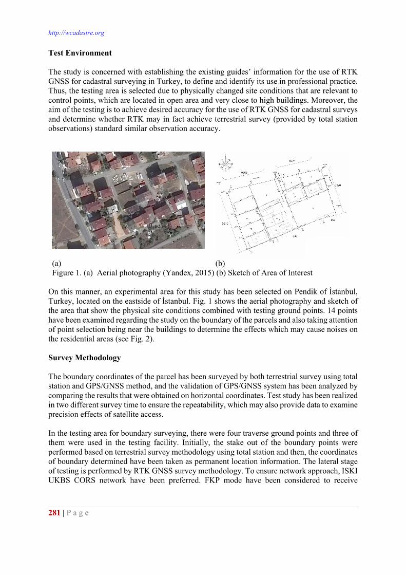
Test Environment The study is concerned with establishing the existing guides’ information for the use of RTK GNSS for cadastral surveying in Turkey, to define and identify its use in professional practice. Thus, the testing area is selected due to physically changed site conditions that are relevant to control points, which are located in open area and very close to high buildings. Moreover, the aim of the testing is to achieve desired accuracy for the use of RTK GNSS for cadastral surveys and determine whether RTK may in fact achieve terrestrial survey (provided by total station observations) standard similar observation accuracy.
(a) (b) Figure 1. (a) Aerial photography (Yandex, 2015) (b) Sketch of Area of Interest
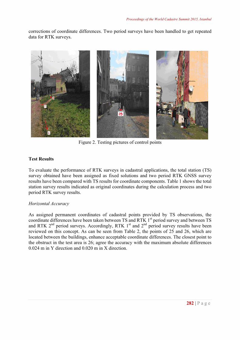
On this manner, an experimental area for this study has been selected on Pendik of İstanbul, Turkey, located on the eastside of İstanbul. Fig. 1 shows the aerial photography and sketch of the area that show the physical site conditions combined with testing ground points. 14 points have been examined regarding the study on the boundary of the parcels and also taking attention of point selection being near the buildings to determine the effects which may cause noises on the residential areas (see Fig. 2). Survey Methodology The boundary coordinates of the parcel has been surveyed by both terrestrial survey using total station and GPS/GNSS method, and the validation of GPS/GNSS system has been analyzed by comparing the results that were obtained on horizontal coordinates. Test study has been realized in two different survey time to ensure the repeatability, which may also provide data to examine precision effects of satellite access. In the testing area for boundary surveying, there were four traverse ground points and three of them were used in the testing facility. Initially, the stake out of the boundary points were performed based on terrestrial survey methodology using total station and then, the coordinates of boundary determined have been taken as permanent location information. The lateral stage of testing is performed by RTK GNSS survey methodology. To ensure network approach, ISKI UKBS CORS network have been preferred. FKP mode have been considered to receive
Proceedings of the World Cadastre Summit 2015, Istanbul
282 | P a g e
corrections of coordinate differences. Two period surveys have been handled to get repeated data for RTK surveys.
Figure 2. Testing pictures of control points
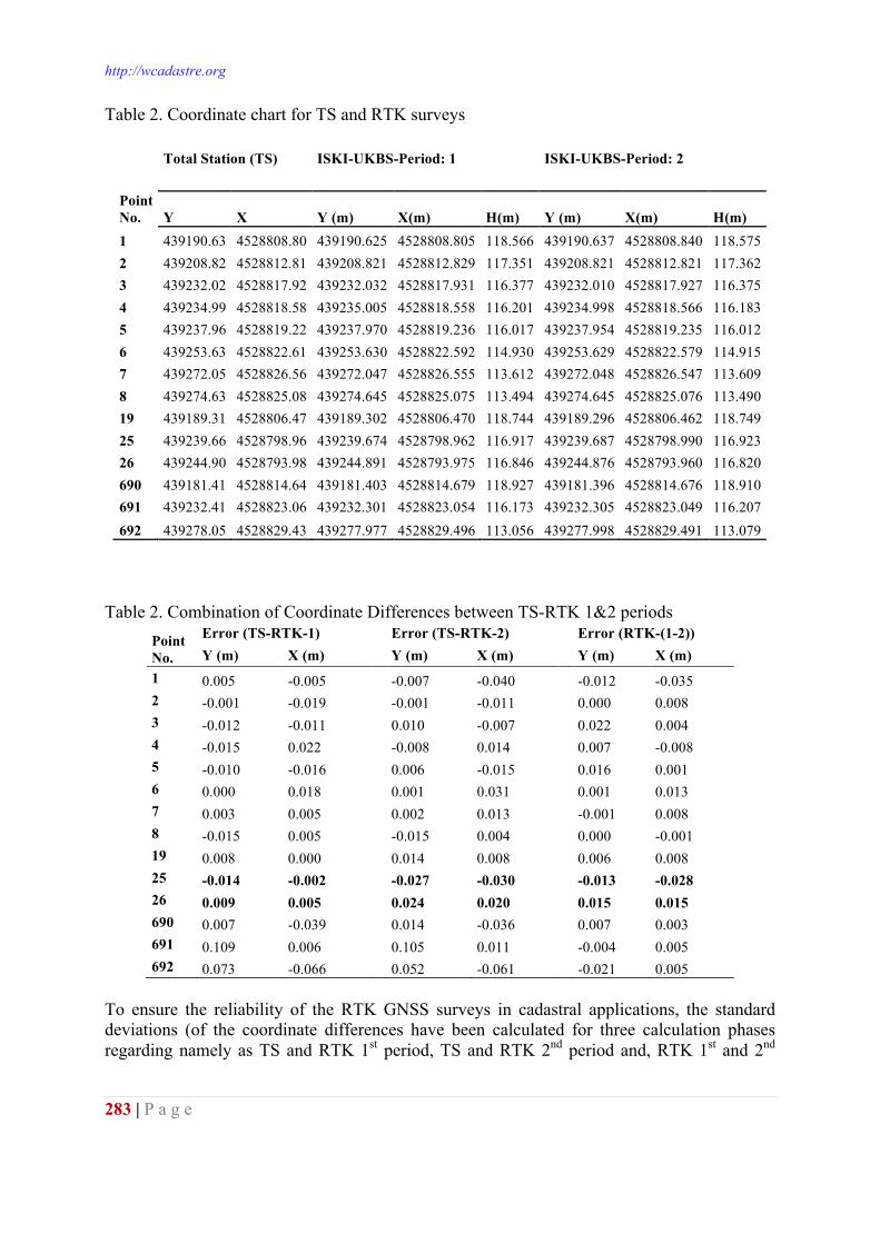
Test Results To evaluate the performance of RTK surveys in cadastral applications, the total station (TS) survey obtained have been assigned as fixed solutions and two period RTK GNSS survey results have been compared with TS results for coordinate components. Table 1 shows the total station survey results indicated as original coordinates during the calculation process and two period RTK survey results. Horizontal Accuracy As assigned permanent coordinates of cadastral points provided by TS observations, the coordinate differences have been taken between TS and RTK 1st period survey and between TS and RTK 2nd period surveys. Accordingly, RTK 1st and 2nd period survey results have been reviewed on this concept. As can be seen from Table 2, the points of 25 and 26, which are located between the buildings, enhance acceptable coordinate differences. The closest point to the obstruct in the test area is 26; agree the accuracy with the maximum absolute differences 0.024 m in Y direction and 0.020 m in X direction.
http://wcadastre.org
283 | P a g e
Table 2. Coordinate chart for TS and RTK surveys
Total Station (TS) ISKI-UKBS-Period: 1 ISKI-UKBS-Period: 2 Point No. Y X Y (m) X(m) H(m) Y (m) X(m) H(m) 1 439190.63 4528808.80 439190.625 4528808.805 118.566 439190.637 4528808.840 118.575 2 439208.82 4528812.81 439208.821 4528812.829 117.351 439208.821 4528812.821 117.362 3 439232.02 4528817.92 439232.032 4528817.931 116.377 439232.010 4528817.927 116.375 4 439234.99 4528818.58 439235.005 4528818.558 116.201 439234.998 4528818.566 116.183 5 439237.96 4528819.22 439237.970 4528819.236 116.017 439237.954 4528819.235 116.012 6 439253.63 4528822.61 439253.630 4528822.592 114.930 439253.629 4528822.579 114.915 7 439272.05 4528826.56 439272.047 4528826.555 113.612 439272.048 4528826.547 113.609 8 439274.63 4528825.08 439274.645 4528825.075 113.494 439274.645 4528825.076 113.490 19 439189.31 4528806.47 439189.302 4528806.470 118.744 439189.296 4528806.462 118.749 25 439239.66 4528798.96 439239.674 4528798.962 116.917 439239.687 4528798.990 116.923 26 439244.90 4528793.98 439244.891 4528793.975 116.846 439244.876 4528793.960 116.820 690 439181.41 4528814.64 439181.403 4528814.679 118.927 439181.396 4528814.676 118.910 691 439232.41 4528823.06 439232.301 4528823.054 116.173 439232.305 4528823.049 116.207 692 439278.05 4528829.43 439277.977 4528829.496 113.056 439277.998 4528829.491 113.079
Table 2. Combination of Coordinate Differences between TS-RTK 1&2 periods
Point No.
Error (TS-RTK-1) Error (TS-RTK-2) Error (RTK-(1-2)) Y (m) X (m) Y (m) X (m) Y (m) X (m)
1 0.005 -0.005 -0.007 -0.040 -0.012 -0.035 2 -0.001 -0.019 -0.001 -0.011 0.000 0.008 3 -0.012 -0.011 0.010 -0.007 0.022 0.004 4 -0.015 0.022 -0.008 0.014 0.007 -0.008 5 -0.010 -0.016 0.006 -0.015 0.016 0.001 6 0.000 0.018 0.001 0.031 0.001 0.013 7 0.003 0.005 0.002 0.013 -0.001 0.008 8 -0.015 0.005 -0.015 0.004 0.000 -0.001 19 0.008 0.000 0.014 0.008 0.006 0.008 25 -0.014 -0.002 -0.027 -0.030 -0.013 -0.028 26 0.009 0.005 0.024 0.020 0.015 0.015 690 0.007 -0.039 0.014 -0.036 0.007 0.003 691 0.109 0.006 0.105 0.011 -0.004 0.005 692 0.073 -0.066 0.052 -0.061 -0.021 0.005
To ensure the reliability of the RTK GNSS surveys in cadastral applications, the standard deviations (of the coordinate differences have been calculated for three calculation phases regarding namely as TS and RTK 1st period, TS and RTK 2nd period and, RTK 1st and 2nd
Proceedings of the World Cadastre Summit 2015, Istanbul
284 | P a g e
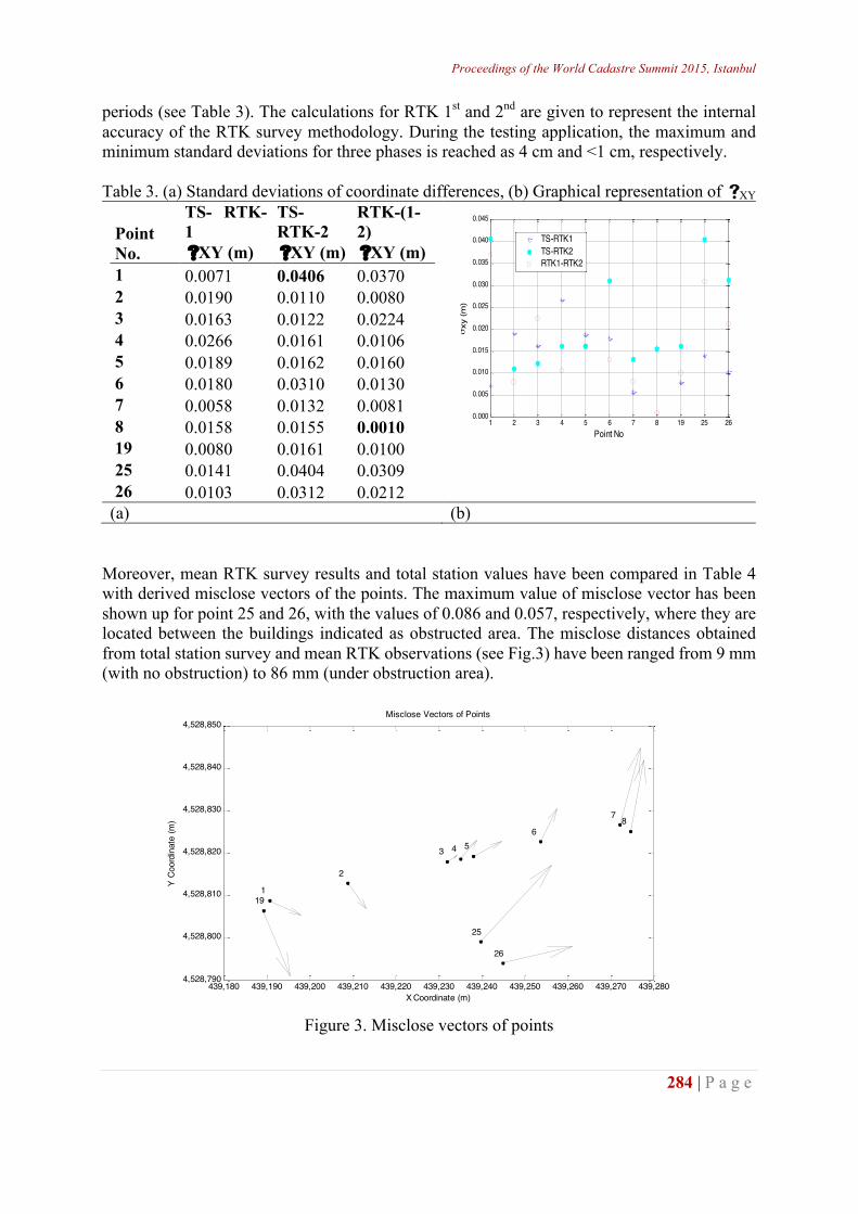
periods (see Table 3). The calculations for RTK 1st and 2nd are given to represent the internal accuracy of the RTK survey methodology. During the testing application, the maximum and minimum standard deviations for three phases is reached as 4 cm and <1 cm, respectively. Table 3. (a) Standard deviations of coordinate differences, (b) Graphical representation of sXY
Point No.
TS- RTK-1
TS- RTK-2
RTK-(1-2)
sXY (m) sXY (m) sXY (m) 1 0.0071 0.0406 0.0370 2 0.0190 0.0110 0.0080 3 0.0163 0.0122 0.0224 4 0.0266 0.0161 0.0106 5 0.0189 0.0162 0.0160 6 0.0180 0.0310 0.0130 7 0.0058 0.0132 0.0081 8 0.0158 0.0155 0.0010 19 0.0080 0.0161 0.0100 25 0.0141 0.0404 0.0309 26 0.0103 0.0312 0.0212
(a) (b) Moreover, mean RTK survey results and total station values have been compared in Table 4 with derived misclose vectors of the points. The maximum value of misclose vector has been shown up for point 25 and 26, with the values of 0.086 and 0.057, respectively, where they are located between the buildings indicated as obstructed area. The misclose distances obtained from total station survey and mean RTK observations (see Fig.3) have been ranged from 9 mm (with no obstruction) to 86 mm (under obstruction area).
Figure 3. Misclose vectors of points
1 2 3 4 5 6 7 8 19 25 260.000
0.005
0.010
0.015
0.020
0.025
0.030
0.035
0.040
0.045
Point No
σxy
(m)
TS-RTK1TS-RTK2RTK1-RTK2
439,180 439,190 439,200 439,210 439,220 439,230 439,240 439,250 439,260 439,270 439,2804,528,790
4,528,800
4,528,810
4,528,820
4,528,830
4,528,840
4,528,850
1
2
3 4 56
7 8
19
25
26
X Coordinate (m)
Y Co
ordi
nate
(m)
Misclose Vectors of Points
http://wcadastre.org
285 | P a g e
Table 4. Coordinates derived from Total Station and RTK surveys Total Station Mean RTK Observation
Point No. Y (m) X(m) Y (m) X(m) Misclose Vector (m) 1 439190.656 4528808.811 439190.631 4528808.823 0.028 2 439208.836 4528812.804 439208.821 4528812.825 0.026 3 439232.029 4528817.934 439232.021 4528817.929 0.009 4 439235.015 4528818.577 439235.002 4528818.562 0.020 5 439237.985 4528819.247 439237.962 4528819.236 0.026 6 439253.643 4528822.613 439253.630 4528822.586 0.031 7 439272.064 4528826.614 439272.048 4528826.551 0.065 8 439274.656 4528825.135 439274.645 4528825.076 0.061
19 439189.321 4528806.412 439189.299 4528806.466 0.058 25 439239.739 4528799.039 439239.681 4528798.976 0.086 26 439244.939 4528793.981 439244.884 4528793.968 0.057
CONCLUSION A case study was conducted to investigate the use of the CORS technique for boundary surveys. For this purpose, measurements were performed in the city of İstanbul, Turkey. Fourteen points were selected in both normal and difficult measurement conditions in the project area. The analyses were made in three steps. In the first step, the CORS results obtained on different periods were compared with each other; in the second, the total station observations have been realized on site to assign as fixed coordinates in evaluations; in the last step, the CORS measurement results were compared with those of the total station. The results showed differences of up to centimeters between the coordinates derived from the two survey methods in the obstructed areas. We conclude that the CORS technique competes well with the traditional survey methods in terms of accuracy, and it can be used in cadastral surveys even in semi residential areas. Moreover, RTK method brings ease of use, efficiency in survey; time and budget save in field works. REFERENCES [1] Tamrakar, Rabindra Man, (2013), Potential Use of GPS Technology For Cadastral Surveys in
Nepal, Nepalese Journal on Geoinformatics, -12, 2070 (2013AD): 33-40 [2] Veersema, Adam, (2004), RTK-GPS for Cadastral Boundary Surveying in NSW, School of
Surveying and Spatial Information Systems, The university of New South Wales [3] Lee, I. and Ge, L., (2006), The performance of RTK-GPS for surveying under challenging
environmental conditions, Earth Planets Space, 58, 515–522 [4] Rizos, C., (1999), GPS enhancements, in Notes on Basics GPS Positioning and Geodetic Concepts,
edited by C. Rizos, School of Surveying and Spatial Information, University of New South Wales, pp. 15–16, electronic version, 1999.
[5] Öcalan, T. and Tunalıoğlu, N., (2010), Data communication for real-time positioning and navigation in global navigation satellite systems (GNSS)/continuously operating reference stations (CORS) networks, Scientific Research and Essays Vol. 5(18), pp. 2630-2639
[6] Mekik, C. and Arslanoglu, M. (2003), Accuracy analysis of real time kinematic GPS positions and a case study. In Proceedings of the 9th Turkish Scientific and Technical Assembly on Mapping, Ankara, Turkey, March 2003; pp. 549-558.
Proceedings of the World Cadastre Summit 2015, Istanbul
286 | P a g e
ANALYSIS AND APPLICABILITY OF TECHNICAL AND LEGAL DOCUMENTS FROM PRE-CADASTRAL WORKS
REGARDING UP-TO- DATE CADASTRAL WORKS IN TURKISH CADASTRAL SYSTEM
Cemal Bıyık, Okan Yıldız, Gamze Yılmaz
Karadeniz Technical University, Trabzon
[email protected] ABSTRACT Surveying and cadastral works based on the maps-bases have been implemented since 1950 in Turkey. Then, technical standards and methods have since been equipped with modern practices. Protection and transfer of property and other real rights related to cadastral parcels has been rigorously carried out by registration them on new Land Registry. If it has been valid documents for the determination and transferring of the rights and obligations on the immovable property, witness statements, related to surveying and registration for cadastral parcels, have not been taken into account on cadastral works. Documents indicating the rights to the parcel on time of cadastral works can be divided into two parts ones rights documents and the others proof documents. Up-to-date title deed, land records and other documents are considered as "right certificate". The documents which are used to prove the existence of a right are considered as "proof documents". Maps and sketches displaying the geometric position of the cadastral parcels are also conditionally evaluated. All of these documents are archived after that finishing the cadastral works to be used in resolving possible disputes that may arise in the future related to cadastral works. In this study, definition of these documents will be made and it will be explained as well as the problems may be encountered in practice. Keywords: Cadastre, Cadastral Documents *Full paper is not submitted.