virtual surveying: mapping and modeling cadastral · pdf filevirtual surveying: mapping and...
TRANSCRIPT

Virtual Surveying: Mapping and Modeling Cadastral Boundaries Using Unmanned Aerial Systems (UAS), (7300) Grenville Barnes and Walter Volkmann (USA) FIG Congress 2014 Engaging the Challenges – Enhancing the Relevance Kuala Lumpur, Malaysia 16-21 June 2014
1/13 Virtual
Virtual Surveying: Mapping and Modeling Cadastral Boundaries Using Unmanned Aerial Systems (UAS)
Walter VOLKMANN and Grenville BARNES, USA
SUMMARY
The fusion, miniaturization of spatial technologies such as GPS and the emergence of affordable platforms to carry these technologies has opened up new opportunities for mapping and modeling cadastral boundaries. High resolution imagery from UAS can now be used to optimize the amount of fieldwork required and offers a more efficient and richer solution for defining property boundaries.
This paper discusses the results of pilot tests carried out in Albania at the end of 2013 through an Innovation Grant within the ECE region of the World Bank. One of the objectives was to design and test a UAS-based methodology for producing precise geo-referenced boundary data that can be used to update or regularize existing cadastral data. We outline the methodology in terms of (a) pre-field preparation and mobilization, (b) field work (including pre-marking, geodetic and ground control, flying), and (c) post-field processing (Multi-view Stereopsis, production of orthophotos and 3-D models, quality control and assessment).

Virtual Surveying: Mapping and Modeling Cadastral Boundaries Using Unmanned Aerial Systems (UAS), (7300) Grenville Barnes and Walter Volkmann (USA) FIG Congress 2014 Engaging the Challenges – Enhancing the Relevance Kuala Lumpur, Malaysia 16-21 June 2014
2/13 Virtual
Virtual Surveying: Mapping and Modeling Cadastral Boundaries Using Unmanned Aerial Systems (UAS)
Walter VOLKMANN and Grenville BARNES, USA
1. INTRODUCTION
Unmanned aerial systems (UAS), UAVs and drones are making the news almost daily, to the extent that some are referring to the emergence of a new field called droneography.1 Unfortunately, these three terms are often conflated and confused with large military drones which are changing the battleground from the field to some remote control station thousands of miles from where the war is being waged. The UAS’ we are dealing with in this paper have nothing to do with warfare and are a fraction of the size and weight. In fact, small UAVs have emerged from the design and manufacturing of (non-military) cell phones. Small, open source UAS’ should therefore not be confused with military drones or even classified as a similar technology. We believe, however, that this technology represents another technological leap much like GPS did in the late 1980s and early 1990s. By providing current, high resolution imagery it has the potential to create a model of the landscape that can be used to survey and map in a virtual mode thus drastically reducing the amount of fieldwork required and offering order of magnitude savings in time.
We are not suggesting that this heralds the end of fieldwork and surveying as we know it. Digging for corner monuments is not currently possible from imagery, although one could imagine the invention of UAVs that can dig for existing monuments or place new corner stones! Similarly, the success of virtual surveying rests on the extent to which one can see and identify features on the landscape, or general boundaries within the context of cadastral surveying. Nevertheless, the potential application of UAS’ for mapping is vast - defining cadastral boundaries, monitoring the construction of roads or buildings, urban planning, upgrading informal settlements, environmental monitoring, asset management, and many other activities that depend on geospatial data.
A number of publications have dealt with the promise of UAS in the areas of property appraisal for taxation purposes (Cunningham et al 2011), modeling buildings to develop a 3-D cadastre (Jazayeri et al 2013) and various other areas that involve geospatial data. Everaerts (2009) lists numerous application areas including archeology, agriculture and monitoring of fires and traffic. In other cases, UAS’ have been field tested but on a very limited area or on just one or two buildings (Manyoky et al 2011; Baiocchi 2013; Neitzel and Klonowski 2011). In the tests described in this paper we tried to cover larger areas that would give us an idea of feasibility of using this technology for land adjudication or regularization. We collaborated with the private sector in Albania and involved local inhabitants and administrators as much as possible. We also 1 See http://droneography.com/

Virtual Surveying: Mapping and Modeling Cadastral Boundaries Using Unmanned Aerial Systems (UAS), (7300) Grenville Barnes and Walter Volkmann (USA) FIG Congress 2014 Engaging the Challenges – Enhancing the Relevance Kuala Lumpur, Malaysia 16-21 June 2014
3/13 Virtual
presented the results of our tests to a group of technical employees of the land registry office (IRPO) and to a broader group of government decisionmakers.
In this paper we briefly describe the components of a UAS, focusing on vertical take-off and landing or VTOL vehicles. We outline the work flow of a typical UAS-based mapping job, including initial testing of the UAS on a control site. Finally, we describe and analyze pilot tests carried out in Albania in December, 2013.
2. UAS COMPONENTS
UAS’ consist of three fundamental components which all interact with each other at some point in the mapping process. These components are:
(a) Unmanned aerial vehicle (UAV) carrying navigation equipment (advanced autopilot module - APM, GPS, inertial measurement unit - IMU), camera (off-the-shelf non-metric cameras are usually cheaper and lighter), battery (Lithium-polymer LiPo);
(b) Laptop or base station on which the initial flight planning is done and which shows real-time navigation, imagery and telemetry information (Lat, Long, GPS quality, etc.);
(c) Remote control (RC) transmitter which can be used to manually control the UAV and which receives basic data on the status of the vehicle (battery voltage, GPS quality, roll, pitch and heading).
UAVs can be divided into two distinct categories – VTOL and fixed wing. VTOL vehicles are generally designed as multi-rotor copters with 3, 4 (‘quadcopter’), 6 (‘hexacopter’) or 8 propellers (‘octocopter’). We used a quadcopter for our pilot tests in Albania and almost all of our experience has been with these types of UAVs.
Fixed wing UAVs are designed much like conventional aircraft which require forward motion to fly and space to take off and land. VTOL vehicles, on the other hand, require very little space for take-off and landing and have the ability to hover if so desired. VTOL UAVs are therefore preferable for smaller areas where high resolution imagery is required. Fixed wing UAVs are likely more productive over large areas, although these will generally be at a lower resolution because of the speed at which these UAVs must fly and the restrictions on camera shutter speeds and continuous exposure rates. When selecting a UAV it is important to consider whether coverage of a whole area is needed at the same time, or whether it is better to map incrementally as the spatial data is needed so that the data is more current.
Virtual Surveying: Mapping and Modeling Cadastral Boundaries Using Unmanned Aerial Systems (UAS), (7300) Grenville Barnes and Walter Volkmann (USA) FIG Congress 2014 Engaging the Challenges – Enhancing the Relevance Kuala Lumpur, Malaysia 16-21 June 2014
4/13 Virtual
3. UAS MAPPING METHODOLOGY
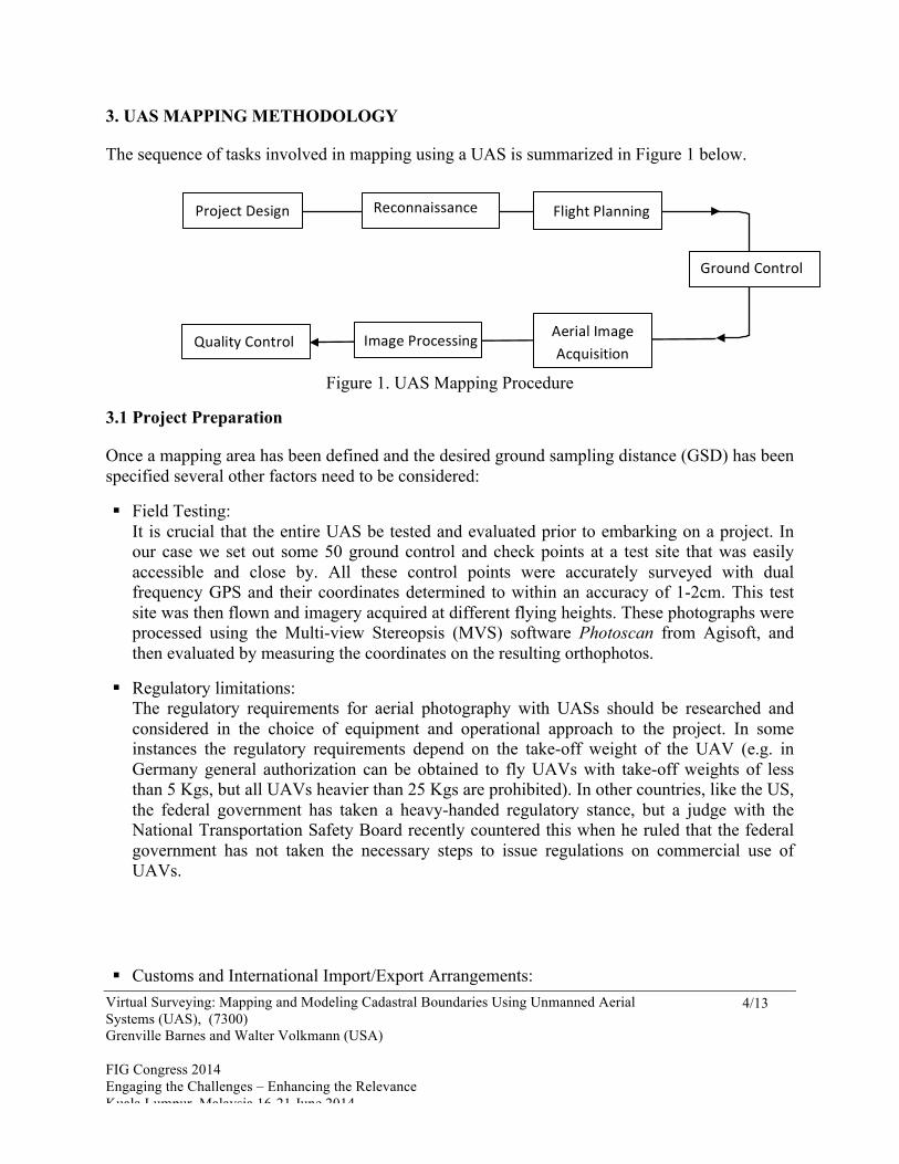
The sequence of tasks involved in mapping using a UAS is summarized in Figure 1 below.
Figure 1. UAS Mapping Procedure
3.1 Project Preparation
Once a mapping area has been defined and the desired ground sampling distance (GSD) has been specified several other factors need to be considered:
! Field Testing: It is crucial that the entire UAS be tested and evaluated prior to embarking on a project. In our case we set out some 50 ground control and check points at a test site that was easily accessible and close by. All these control points were accurately surveyed with dual frequency GPS and their coordinates determined to within an accuracy of 1-2cm. This test site was then flown and imagery acquired at different flying heights. These photographs were processed using the Multi-view Stereopsis (MVS) software Photoscan from Agisoft, and then evaluated by measuring the coordinates on the resulting orthophotos.
! Regulatory limitations: The regulatory requirements for aerial photography with UASs should be researched and considered in the choice of equipment and operational approach to the project. In some instances the regulatory requirements depend on the take-off weight of the UAV (e.g. in Germany general authorization can be obtained to fly UAVs with take-off weights of less than 5 Kgs, but all UAVs heavier than 25 Kgs are prohibited). In other countries, like the US, the federal government has taken a heavy-handed regulatory stance, but a judge with the National Transportation Safety Board recently countered this when he ruled that the federal government has not taken the necessary steps to issue regulations on commercial use of UAVs.
! Customs and International Import/Export Arrangements:
Project Design
Quality Control Image Processing Aerial Image Acquisition
Reconnaissance Flight Planning
Ground Control
Virtual Surveying: Mapping and Modeling Cadastral Boundaries Using Unmanned Aerial Systems (UAS), (7300) Grenville Barnes and Walter Volkmann (USA) FIG Congress 2014 Engaging the Challenges – Enhancing the Relevance Kuala Lumpur, Malaysia 16-21 June 2014
5/13 Virtual
If the project is international, import/export restrictions and customs and duty arrangements should be investigated for international projects. Equipment that was manufactured without any military aid, or for strictly non-military purposes, generally has fewer restrictions.
! Travel Mode to Site: When having to travel to the site on commercial airlines it is much more convenient to use a UAV that can be packed into cases small enough to carry as accompanying luggage. Larger UAVs require prior shipping by airfreight, thus increasing logistical complexity and the risk of delays. Lithium-polymer (LiPo) batteries are subject to very strict packaging and shipping specifications and it is therefore advisable to carry these batteries in a fire-proof case that can be transported as carry-on luggage.
3.2 Reconnaissance
Even though we use Google Earth (GE) to do an initial review of the project area, it is essential to do an on-site reconnaissance as the GE imagery is often not current and/or does not show dangerous obstructions such as cell towers, power lines or other objects that could impede the flight plan. Part of the reconnaissance includes identifying an open, reasonably central location that can be used as the take-off and landing area. It should be reiterated that with VTOL UAVs this area does not have to be larger than about 10 square meters.
3.3 Flight Planning
Flight planning is determined by several factors which may change from one application to the next. These are (i) the desired ground resolution usually expressed in terms of ground sampling distance or GSD (the ground footprint of one image pixel (p)), (ii) the focal length (f) and resolution of the camera, (iii) the flying height (H) calculated as GSD x (f/p), and (iv) the required forward and lateral overlap.
In our pilot tests in Albania we used a camera with a focal length of 16mm and flew at a height of 75m above the ground giving us a GSD of 18mm in the agricultural test area. In the urban test area we flew 50m above the rooftops using the same camera giving us GSDs varying from 13mm on the rooftops to 20mm at ground level.
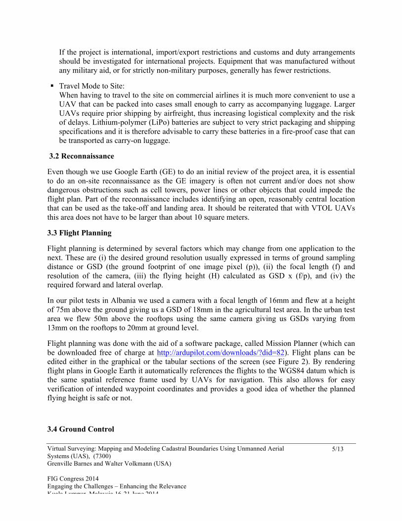
Flight planning was done with the aid of a software package, called Mission Planner (which can be downloaded free of charge at http://ardupilot.com/downloads/?did=82). Flight plans can be edited either in the graphical or the tabular sections of the screen (see Figure 2). By rendering flight plans in Google Earth it automatically references the flights to the WGS84 datum which is the same spatial reference frame used by UAVs for navigation. This also allows for easy verification of intended waypoint coordinates and provides a good idea of whether the planned flying height is safe or not.
3.4 Ground Control
Virtual Surveying: Mapping and Modeling Cadastral Boundaries Using Unmanned Aerial Systems (UAS), (7300) Grenville Barnes and Walter Volkmann (USA) FIG Congress 2014 Engaging the Challenges – Enhancing the Relevance Kuala Lumpur, Malaysia 16-21 June 2014
6/13 Virtual
Ground control can be eliminated or drastically minimized if the UAV has a dual frequency GNSS on board so that precise camera station coordinates are determined for each photograph. If this is not the case it will be necessary to pre-mark and survey ground control points (GCPs) that can be positively identified in the aerial images. Ideally, they should be pre-marked immediately before flying by placing targets of appropriate shape and color in a more or less even distribution across the project area. Existing natural or artificial features on the landscape can be used provided they can be clearly identified in the aerial photographs. All GCPs are surveyed to determine their precise coordinates in a defined spatial reference frame. In most cases ground control points are surveyed by means of differential GNSS to an accuracy of 2cm or better.
3.5 Acquire Aerial Imagery
At the take-off site the connections between the UAV and the RC transmitter and base station connections to the UAV are activated and the flight mission plan is uploaded to the UAV flight controller. Prior to take-off it is a good idea to mentally rehearse the planned flight routine and to locate possible landing sites should a manually executed emergency landing be necessary.
Figure 2. Mission Planner interface showing project area (blue) and flight lines (yellow) for one flight
It is always good practice to use the manual mode for the first take-off at any given site to test the operation of the UAS. This includes a test for radio interference and secure communication

Virtual Surveying: Mapping and Modeling Cadastral Boundaries Using Unmanned Aerial Systems (UAS), (7300) Grenville Barnes and Walter Volkmann (USA) FIG Congress 2014 Engaging the Challenges – Enhancing the Relevance Kuala Lumpur, Malaysia 16-21 June 2014
7/13 Virtual
between the RC transmitter and the UAV, since manual control over the UAV after take-off depends on this communication. With VTOL UAVs this is done by hovering about 2m above the ground to ensure that it is stable. The main purpose of these tests is the early detection of site specific conditions that may affect the safety and feasibility of the planned flights.
When the take-off site is clear the UAV may be launched in a manual or automatic mode. Once the UAV is switched over to automatic mode it should be observed at all times and the operator should be ready to override the automatic mode if necessary. Where this is not possible, the progress and flight telemetry of the UAV should be closely monitored on the RC transmitter and the base station computer (See Figure 3). It is particularly important to monitor the energy levels of the UAV flight batteries and to look out for other air traffic. It is also a good idea to identify the nearest and safest emergency landing sites, should the need arise. Because batteries will only power the UAV for 10-15 minutes, larger projects will generally require several different flights. In Figure 3 below, the take-off site (home) is located on top of a building some distance away from the flight lines of the first flight. The UAV will automatically fly to the start point (1) and then follow the designated flight lines for that particular flight. Once it has completed those flight lines (at point 10 on Figure 3), it will automatically return to the home site or a location close to home from which it is landed in a manual mode. The manual landing is advisable where there are obstructions around the landing site.
Figure 3. Base station computer display of the telemetry (Komuna Farke, Albania)
It is good practice to inspect the UAV motors or electronics immediately after landing to detect any signs of overheating. The aerial images should also be inspected for quality after the first flight and any required adjustments made to the camera settings before further flights.
Virtual Surveying: Mapping and Modeling Cadastral Boundaries Using Unmanned Aerial Systems (UAS), (7300) Grenville Barnes and Walter Volkmann (USA) FIG Congress 2014 Engaging the Challenges – Enhancing the Relevance Kuala Lumpur, Malaysia 16-21 June 2014
8/13 Virtual
If the aerial images are geo-referenced directly with an on-board GNSS receiver, the camera exposure positions can be plotted on Google Earth or in a GIS to check whether the acquisition went according to plan.
3.6 Image Processing
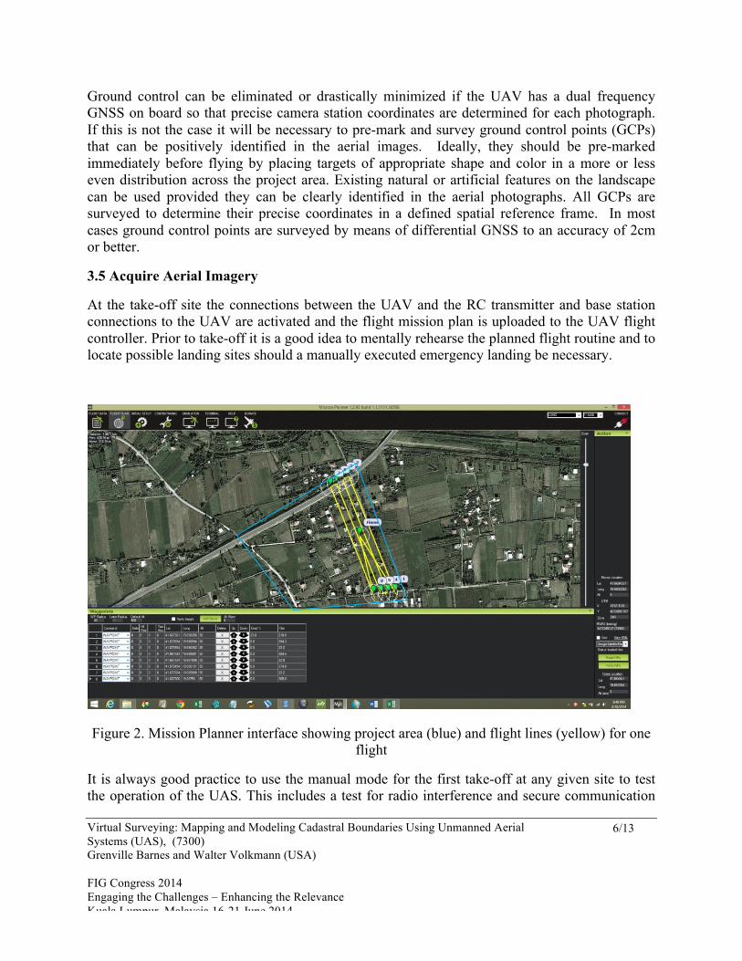
Flights that are designed with generous overlaps of 80% (forward) and 70% (lateral) produce a large number of overlapping photographs (see Figure 4) amounting to large datasets (each photograph is about 4-5 mb). Consequently, the processing part of the UAS methodology is the most time-consuming.
Figure 4. Overlapping UAS Photos of Fushe Milot (Albania)
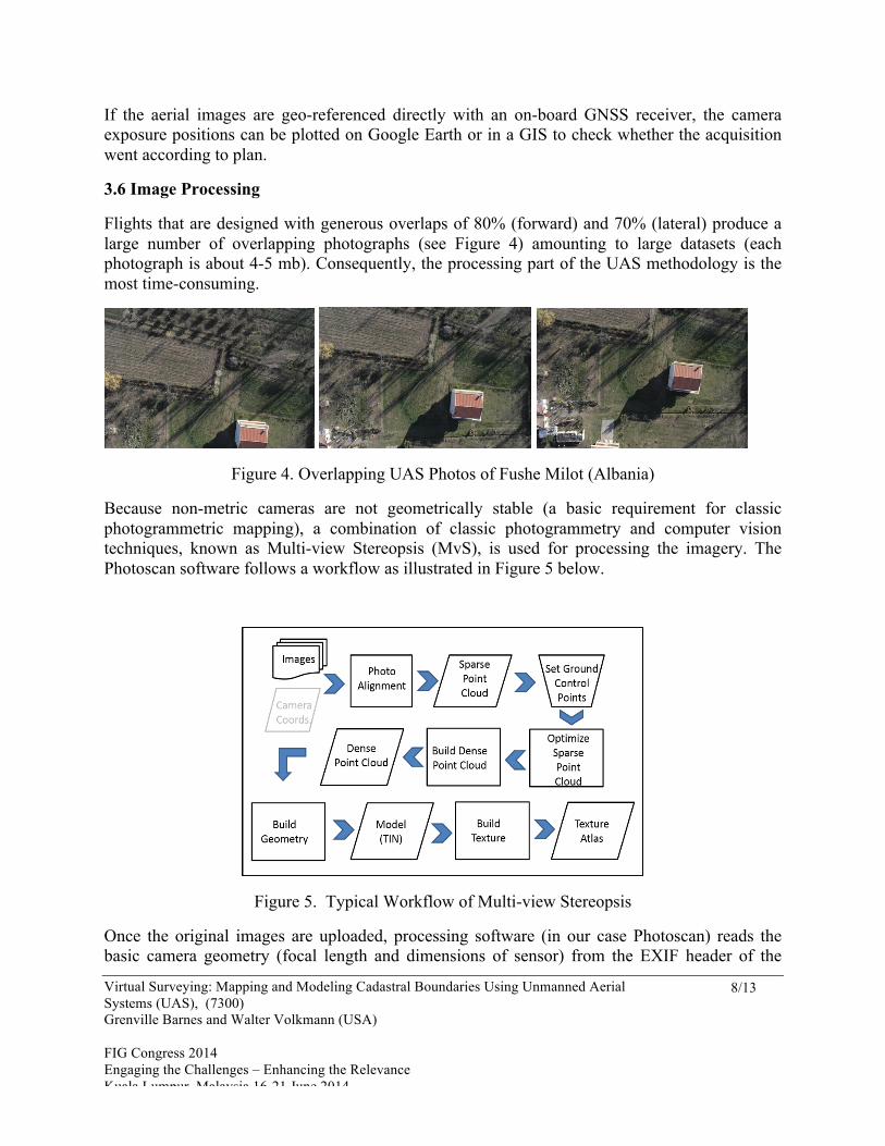
Because non-metric cameras are not geometrically stable (a basic requirement for classic photogrammetric mapping), a combination of classic photogrammetry and computer vision techniques, known as Multi-view Stereopsis (MvS), is used for processing the imagery. The Photoscan software follows a workflow as illustrated in Figure 5 below.
Figure 5. Typical Workflow of Multi-view Stereopsis Once the original images are uploaded, processing software (in our case Photoscan) reads the basic camera geometry (focal length and dimensions of sensor) from the EXIF header of the

Virtual Surveying: Mapping and Modeling Cadastral Boundaries Using Unmanned Aerial Systems (UAS), (7300) Grenville Barnes and Walter Volkmann (USA) FIG Congress 2014 Engaging the Challenges – Enhancing the Relevance Kuala Lumpur, Malaysia 16-21 June 2014
9/13 Virtual
image files and performs a procedure referred to as photo alignment. Photo alignment produces relative camera exposure coordinates, a camera calibration for each and every image as well as a “sparse point cloud. For low accuracy requirements this may be all that is required to build a model if the final product does not have to be referenced to some spatial reference frame. However, the process of determining the camera exposure positions is significantly accelerated if approximate positions are introduced into the photo alignment procedure. Typically, these approximate positions are obtained from the stand-alone navigation GPS receiver mounted on board the UAV. However, if the product is to be accurately geo-referenced to a defined coordinate system (e.g. WGS84/UTM), then GCPs need to be provided.
For accurate geo-referencing, the absolute coordinates of GCPs should be measured to an accuracy equivalent to the GSD of the imagery. GCPs are measured quite simply by identifying each GCP target in every photo on which it appears and centering a flag on each of those locations. With forward and lateral overlaps of 80% and 70%, a single GCP can appear on as many as 10-16 different photos. These measurements are used to compute linear transformation parameters to transform the model from an arbitrary local system to the spatial reference framework of the GCPs. The software does an error analysis and displays the results enabling the user to identify and eliminate any blunders. After this step, the sparse point cloud is re-transformed for optimum positioning in the coordinate system of the GCPs and the camera positions are adjusted accordingly. The only manual task in the entire workflow is the observation of the GCP image coordinates in each photo in which they appear.
In the next step of the image processing workflow the software uses the optimized sparse point cloud and improved camera positions to generate a dense point cloud of the project area (see Figure 5). The generation of the dense point cloud usually takes the longest time of all the processing steps.
Figure 6. Dense Point Cloud of Fushe Milot (Albania)

Virtual Surveying: Mapping and Modeling Cadastral Boundaries Using Unmanned Aerial Systems (UAS), (7300) Grenville Barnes and Walter Volkmann (USA) FIG Congress 2014 Engaging the Challenges – Enhancing the Relevance Kuala Lumpur, Malaysia 16-21 June 2014
10/13
From this point it is relatively simple, although time consuming, to generate a surface model in the form of a triangulated irregular network (TIN) (see) as well as a texture atlas that is used to create a true color orthophoto (see Figure 7).
Figure 7. Orthophoto of Fushe Milot (Albania)
3.7 Pilot Tests in Albania
With funding from an ECA Innovation Grant within the World Bank (Kelm et al 2013), we were able to test a UAS approach in December 2013 mapping and spatial modeling in both rural and urban areas. We carried out tests in three pre-selected areas in Albania:
! An agricultural area (called Fushe Milot) comprising approximately 23 hectares located on the coastal plain about 40 kilometers from the capital city of Tirana. This was selected because it is the proposed site of a new urban water supply scheme and it has recently been subject to expropriation to allow for the construction of a new highway which was complete at the time of our visit;
! A dense high-rise area (Komuna Farke) urban expansion covering approximately 65 hectares located on the southern fringe of Tirana close to the largest dam in the area. This site was chosen to test the performance of the UAS in high density urban environments.
Virtual Surveying: Mapping and Modeling Cadastral Boundaries Using Unmanned Aerial Systems (UAS), (7300) Grenville Barnes and Walter Volkmann (USA) FIG Congress 2014 Engaging the Challenges – Enhancing the Relevance Kuala Lumpur, Malaysia 16-21 June 2014
11/13
! A strip of the Elbasan national highway (800m long) approximately 10 kilometers from Tirana that had been partially constructed. This was selected to investigate the application of UAS for monitoring and managing linear features such as roads, powerlines or pipelines.
A flying height of 75 meters above the ground was used for Fushe Milot and the Elbasan Highway, while at the Komuna Farke site we flew generally at a height of 50 meters above the tops of the buildings. In total, we flew 21 flights covering a distance of about 40 kilometers. In the process we took some 4200 aerial photographs with a ground resolution of close to 2 centimeters.
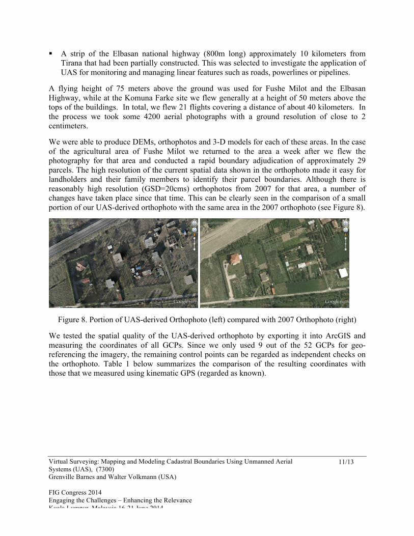
We were able to produce DEMs, orthophotos and 3-D models for each of these areas. In the case of the agricultural area of Fushe Milot we returned to the area a week after we flew the photography for that area and conducted a rapid boundary adjudication of approximately 29 parcels. The high resolution of the current spatial data shown in the orthophoto made it easy for landholders and their family members to identify their parcel boundaries. Although there is reasonably high resolution (GSD=20cms) orthophotos from 2007 for that area, a number of changes have taken place since that time. This can be clearly seen in the comparison of a small portion of our UAS-derived orthophoto with the same area in the 2007 orthophoto (see Figure 8).
Figure 8. Portion of UAS-derived Orthophoto (left) compared with 2007 Orthophoto (right)
We tested the spatial quality of the UAS-derived orthophoto by exporting it into ArcGIS and measuring the coordinates of all GCPs. Since we only used 9 out of the 52 GCPs for geo-referencing the imagery, the remaining control points can be regarded as independent checks on the orthophoto. Table 1 below summarizes the comparison of the resulting coordinates with those that we measured using kinematic GPS (regarded as known).

Virtual Surveying: Mapping and Modeling Cadastral Boundaries Using Unmanned Aerial Systems (UAS), (7300) Grenville Barnes and Walter Volkmann (USA) FIG Congress 2014 Engaging the Challenges – Enhancing the Relevance Kuala Lumpur, Malaysia 16-21 June 2014
12/13
Table 1. Error Analysis of GCPs
(metres) GCPs in model Independent GCPs Mean Linear Error (XY) 0.056 0.061 Mean Z Error 0.009 0.012 CEP50* 0.051 0.057
*Circular Error Probable at 50% Confidence Level
While these statistics are reasonably good and consistent with other tests (Eisenbeiss et al 2013), we are concerned about a handful of GCPs which had positional errors between 10 and 14 cm. Other studies have achieved “precisions” of 2-3cm in the horizontal and 4-10cm in the vertical (Devriendt 2014, p. 23). We are currently analyzing this data from Albania to identify possible sources of error and to improve the 3-D modeling of complex landscapes.
4. CONCLUSIONS
Our pilot tests in Albania convinced us even more that UASs offer a radically new approach to mapping and spatial data acquisition. This approach would enable individuals or small enterprises in developing countries to acquire mapping capacities which could deliver current spatial data at unprecedented resolutions. It also promises order of magnitude savings over conventional mapping approaches in terms of time and cost. Interestingly, Rijsdijk et al (2013) came to the opposite conclusion that “costs are too high at the moment, compared to traditional methods.” We believe the difference lies in what kind of UAV is used and especially on how the workflow from image acquisition to analysis and consumption of the geo-spatial products is structured. Initially, the only UAVs that were available for mapping work were large, expensive vehicles. Over the past 2-3 years, the cost and size of UAVs has dropped significantly, partly due to the strong open source and do-it-yourself culture (see http://diydrones.com/) that has arisen in this sector. UAVs, such as the one used in our Albanian tests, are now available at unit costs that are lower than conventional total station or GNSS rover prices. The real cost savings are in the increased technological efficiencies, the incremental approach to map production and the associated shortening of the supply chain (Anderson 2010; 2013).
Finally, we believe that UAS applications can facilitate the participation of local community members so that they trust and support the products of a methodology that is much more transparent than those that use either remote sensing or aerial photography.

Virtual Surveying: Mapping and Modeling Cadastral Boundaries Using Unmanned Aerial Systems (UAS), (7300) Grenville Barnes and Walter Volkmann (USA) FIG Congress 2014 Engaging the Challenges – Enhancing the Relevance Kuala Lumpur, Malaysia 16-21 June 2014
13/13
References
Anderson, C. (2006). The Long Tail, Hyperion. New York, NY Anderson, C. (2012). Makers: The New Industrial Revolution. Random House, New York, NY Baiocchi, V., D. Dominici, M. Milone and M. Mormile (2013). UAV Application in Post -
Seismic Environment, Presentation at UAV-g Conference, Rostock University, Rostock, Germany
Cunningham, K., G. Walker, E. Stahlke and R. Wilson (2011). Cadastral Audit and Assessments Using Unmanned Aerial Systems.’ Proceedings of ISPRS and UAV-g, Zurich, Switzerland. http://www.teamconsulting.cc/images/uav-geomatics.pdf
Devriendt, L. (2014). ‘Low-Speed and Low-Altitude UAS.’ GIM International, 1(28) Eisenbeiss, H., M. Sauerbier , Ch. Wildi (2013). Presentation at UAV-g Conference, Rostock
University, Rostock, Germany. http://www.uav-g.org/Presentations/UAV-g_2013_%20Eisenbeiss_Web.pdf
Everaerts, J. (2009). Unconventional Platforms (Unmanned Aircraft Systems) for Remote Sensing. Research Report No. 56, European Spatial Data Research,57-102
Jazayeri, I, A. Rajabifard and M. Kalantari (2013). ‘A Geometric and Semantic Evaluation of 3D Data Sourcing Methods for Land and Property Information.’ Land Use Policy, 36: 219-230
Kelm et al (2013). ‘Multi-purpose Spatial Data Capture.’ ECA Region 2013 Innovation Grant Proposal, World Bank, Washington, D.C.
Manyoky, M, P. Theiler, D. Steudler and H. Eisenbeiss (2011). ‘Unmanned Aerial Vehicle in Cadastral Applications.’ Proceedings of ISPRS and UAV-g, Zurich, Switzerland. http://www.geometh.ethz.ch/uav_g/proceedings/manyoky
Neitzel, F. and J. Klonowski (2011). ‘Mobile 3D Mapping with a Low-Cost UAV System.’ Proceedings of ISPRS and UAV-g, Zurich, Switzerland. http://www.geometh.ethz.ch/uav_g/proceedings/neitzel
Rijsdijk, M. et al. (2013). ‘Unmanned Aerial Systems in the process of Juridical Verification of Cadastral Borders.’ Presentation at UAV-g Conference, Rostock University, Rostock, Germany. http://www.uav-g.org/Presentations/UAS_for_Cadastal_Applications/Rijsdijk_M-UAS_in_the_process_of_juridical_verification.pdf