the peak of magnified observation microscope …microfluidics.cnsi.ucsb.edu/tools/keyence...
TRANSCRIPT

NEW
MICROSCOPE LENSL I N E U P C ATA LO G
THE PEAK OF MAGNIFIED OBSERVATION
MicroscopeGeneral Catalog for Lenses and Stands

2
KEYENCE Optical lenses continue to evolve To take you beyond high resolution to enhanced ease of operation
Since selling our first laser photoelectric switch, KEYENCE has launched
numerous products equipped with laser optic technology.
Laser displacement sensors, machine vision, 3-Axis control laser markers,
laser microscopes, and digital microscopes. All of these products are
equipped with optical lenses. We continually ask ourselves:
What can we do to deliver the best observation image?
What is required to achieve the highest level of operability?
KEYENCE's optical design technology is the result of our
many years of experience.
All of this technology is poured into our optical microscope lenses.

3
THE H IGHEST L EVEL OF L ENS DEVELOPMENT
The resolution of the observed image in a microscope depends on the optical lens properties. Mindful of their critical role, KEYENCE has worked to develop lenses that meet the highest standard of perfection. The RZ-LENS is the result of our commitment and boasts the highest level of resolution in the industry.
Fixed lenses Zoom lenses High resolutionRZ lenses

4
Bump (500x)
5
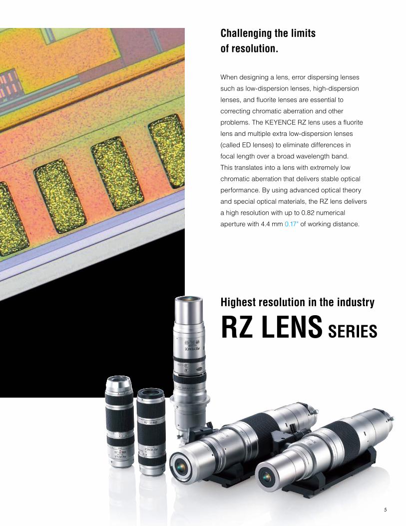
Highest resolution in the industry
RZ LENS SERIES
Challenging the limits of resolution.
When designing a lens, error dispersing lenses
such as low-dispersion lenses, high-dispersion
lenses, and fluorite lenses are essential to
correcting chromatic aberration and other
problems. The KEYENCE RZ lens uses a fluorite
lens and multiple extra low-dispersion lenses
(called ED lenses) to eliminate differences in
focal length over a broad wavelength band.
This translates into a lens with extremely low
chromatic aberration that delivers stable optical
performance. By using advanced optical theory
and special optical materials, the RZ lens delivers
a high resolution with up to 0.82 numerical
aperture with 4.4 mm 0.17" of working distance.

6

7
Inspecting surface roughness with an interferometer
Surface coating Hand-assembled lens
Sophisticated polishing and assembly technology enables high-resolution observation
The RZ Lens Series boasts a maximum optical magnification
of 5000 times. This level of performance demands the most
exacting levels of machining and assembly technology.
Every process from lens polishing and coating to the
machining of parts like the lens tube and cam, as well as
the assembly and quality inspection, are performed as an
integrated process. Strict quality checks in each process
ensure exceptional performance and quality.
For example, look at the objective glass lens, considered the
heart of the lens. It is polished using an ultra-fine polishing
process precise enough to keep the margin of error in the
height of an area the size of the Alamodome to the thickness
of a single sheet of copy paper. Skilled technicians using
advanced assembly techniques assemble this precision-
polished lens and precision-finished lens tube. This high
level of optical technology supports the inherent ability digital
microscopes have for revealing every detail.

8
Ergonomically superior operability
Look at the VH-Z20R for example.
While a larger diameter would have been more advantageous in terms of optical characteristics, the easier to
handle ø38 mm ø1.50" diameter lens was chosen for ergonomic comfort, whether stand-mounted or hand-held.
In addition, chromatic aberration was corrected by selecting the best suited lens materials from dozens of choices,
in order to maintain high resolution and deep depth of field. It takes sophisticated optical techniques to maintain
brightness within a limited lens diameter. KEYENCE overcame the difficulties associated with machining and
assembling zoom mechanisms by developing the ultra small ø38 mm ø1.50" zoom lens.
Coupling sensor technology with optical technique Automatic Lens/Zoom Recognition, DOUBLE'R
KEYENCE coupled its years of experience in sensor technology with the optical technology of digital microscopes.
Changes in lens power are sensed and signaled to the controller. When the controller receives this signal,
it automatically updates internal calibration data and changes the power notation and scale display.

9

10

11
Quick-connect lenses
KEYENCE microscope optic lenses use an original Bayonet mount for quick-connect and disconnect from the
camera. The lens can be removed and attached by twisting the tabs. This makes lens replacement easier than with
threaded mounts. The design also supports C-mount lenses.
Dual light system
Look at the VH-Z250R for example.
It is the industry's first lens to incorporate both coaxial vertical illumination and ring illumination, a feature made
possible with KEYENCE's original optical technology. Because there is no need to replace the lens or illumination,
anyone can easily and quickly switch between lighting methods.
Optical 10x zoom lens
The RZ lenses cover a wide zoom range from 0.1x to 5000x, each with an optical 10x zoom range. To achieve an
optical 10x zoom, highly skilled assembly techniques are required to eliminate the tiniest amount of error in the
zoom mechanism. The wide range design of the RZ lens allows seamless viewing of targets from macro-view to
micro-view. It also maintains a fixed observation distance over the full zoom range, making it easy to work with.
This all-around zoom lens is suitable for any application.
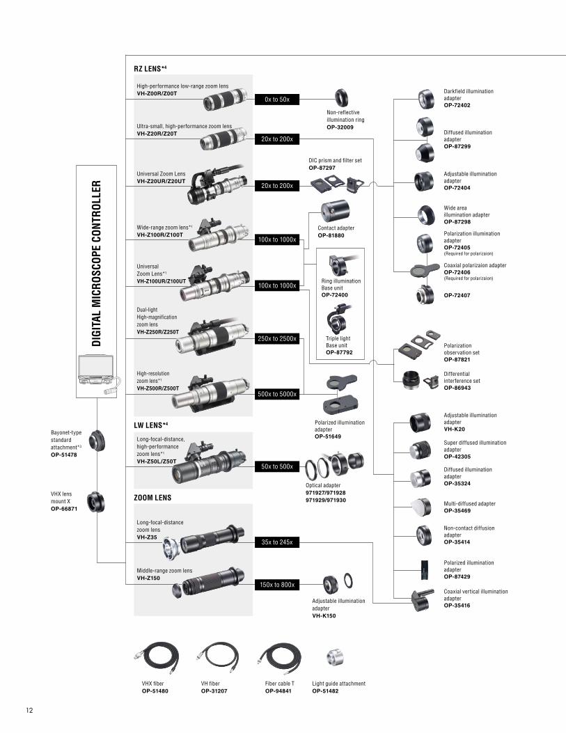
12
100x to 1000x
250x to 2500x
500x to 5000x
UniversalZoom Lens*1
VH-Z100UR/Z100UT
Dual-lightHigh-magnificationzoom lensVH-Z250R/Z250T
High-resolutionzoom lens*1
VH-Z500R/Z500T
VHX fiberOP-51480
Bayonet-typestandardattachment*3
OP-51478
VHX lensmount XOP-66871
VH fiberOP-31207
Fiber cable TOP-94841
Light guide attachmentOP-51482
DIGI
TAL
MIC
ROSC
OPE
CONT
ROLL
ER
Long-focal-distancezoom lensVH-Z35
Long-focal-distance,high-performance zoom lens*1
VH-Z50L/Z50T
High-performance low-range zoom lensVH-Z00R/Z00T
Ultra-small, high-performance zoom lensVH-Z20R/Z20T
Universal Zoom LensVH-Z20UR/Z20UT
Wide-range zoom lens*1
VH-Z100R/Z100T
Middle-range zoom lensVH-Z150
Adjustable illumination adapterVH-K150
ZOOM LENS
LW LENS*4
150x to 800x
35x to 245x
50x to 500x
0x to 50x
20x to 200x
20x to 200x
100x to 1000x
Optical adapter971927/971928971929/971930
Non-reflective illumination ringOP-32009
Darkfield illumination adapterOP-72402
Diffused illumination adapterOP-87299
Adjustable illumination adapterOP-72404
Contact adapterOP-81880
Ring illuminationBase unitOP-72400
Triple lightBase unitOP-87792
DIC prism and filter setOP-87297
RZ LENS*4
Polarized illumination adapterOP-51649
Wide areaillumination adapterOP-87298
Polarization illumination adapterOP-72405(Required for polarizaion)
Polarization observation setOP-87821
Differential interference setOP-86943
OP-72407
Coaxial polarizaion adapterOP-72406(Required for polarizaion)
Adjustable illumination adapterVH-K20
Super diffused illuminationadapterOP-42305
Diffused illumination adapterOP-35324
Non-contact diffusionadapterOP-35414
Coaxial vertical illuminationadapterOP-35416
Polarized illumination adapterOP-87429
Multi-diffused adapterOP-35469

13
*1. The optional light guide dedicated to the VHX Series is required. OP-51480: VH-Z100R/Z100UR/Z500R/Z50L*2. The optional light guide attachment (OP-51482) dedicated to the VHX Series is required.*3. For the VH-Z50L/VH-Z100R/VH-Z250R/VH-Z500R, OP-51647 is required.*4. TRIPLE’R compliant lenses VH-Z00T/Z20T/Z20UT/Z100T/Z100UT/Z250T/ Z500T/Z50T are fitted with Automatic Lens/Zoom Recognition units, respectively.*5. The optional bore fiber cable (OP-87201) is required.
C O N T E N T S
OPTION
HIGH RESOLUTION RZ LENSES
High-performance Low-range Zoom LensVH-Z00R/Z00T
P.14
Ultra-small, High-performance Zoom LensVH-Z20R/Z20T
P.16
Wide-range Zoom LensVH-Z100R/Z100T
P.18
Universal Zoom LensVH-Z100UR/Z100UT
P.20
Dual Light High-magnification Zoom LensVH-Z250R/Z250T
P.22
High-resolution Zoom LensVH-Z500R/Z500T
P.24
LONG DISTANCE LW LENSES
Long-focal-distance, High-performance Zoom LensVH-Z50L/Z50T
P.26
OTHER LENSES
Previous Zoom Lens Specifications P.28
Borescope Lens P.29
OPTIONAL STAND
Free-angle Observation System (XYZ Motorized)VHX-S550E
P.30
Free-angle Observation SystemVHX-S30F/S30BVibration-proof, High-magnification Observation SystemVH-S5
P.31
3D Profile Automatic Measurement UnitVHX-S15 Series
P.32
XY Measurement SystemVH-M100 Series
P.33
LENS KNOWLEDGE 1&2 Lens Information P.34
LENS PRODUCTION P.37
Free-angle observationsystem (XYZ-axis motorized with transmitted illumination)VHX-S550E
Free-angle observation system (Z-axis motorized, manual XY)VHX-S500E
Free-angleobservationsystemVH-S30F/S30B
Free-angle observationsystem (Z-axis automatic)VHX-S90F/S30B
X-Y measurement systemVH-M100
High-precision stand(with X-Y stage andtransmitted illumination)VH-S5
VH lens mountingstandOP-25539
XY stageOP-22124
BORESCOPE LENS*5
VH-B100
VH-B55
VH-B40
VH-B27
VH-B18
VH-BA
FIBERSCOPE*2
VH-F61
VH-F111
Bayonet-type C-mount attachmentOP-51479
VH-F
14
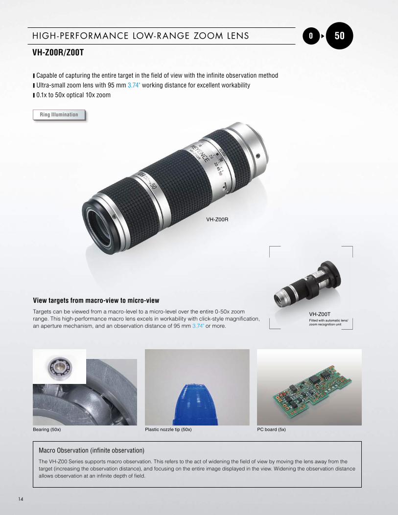
0 50HIGH -PERFORMANCE LOW-RANGE ZOOM LENS
VH-Z00R/Z00T
y Capable of capturing the entire target in the field of view with the infinite observation methody Ultra-small zoom lens with 95 mm 3.74" working distance for excellent workabilityy 0.1x to 50x optical 10x zoom
Bearing (50x) Plastic nozzle tip (50x) PC board (5x)
Macro Observation (infinite observation)
The VH-Z00 Series supports macro observation. This refers to the act of widening the field of view by moving the lens away from the target (increasing the observation distance), and focusing on the entire image displayed in the view. Widening the observation distance allows observation at an infinite depth of field.
VH-Z00R
VH-Z00TFitted with automatic lens/zoom recognition unit
View targets from macro-view to micro-view
Targets can be viewed from a macro-level to a micro-level over the entire 0-50x zoom range. This high-performance macro lens excels in workability with click-style magnification, an aperture mechanism, and an observation distance of 95 mm 3.74" or more.
Ring Illumination

HIGH RESOLUTION RZ LENSES
15
9.7
117.3
ø36
ø1.4
2"
ø1.5
"ø3
8
VH-Z00R VH-Z00T
95 95 (Observation distance)(Observation distance)
3.74" 3.74" 2.81" 0.80"
4.30"4.74"5.16"
4.62"
0.38"
ø1.5
"
1.14
"
ø2.3
6"
ø1.9
7"
120.3109.3
ø 60
131
ø 50
20.371.3
ø 3828
.9
This observation method is used to observe light reflected off the target by projecting light from the sides of the lens. Referred to as dark-field observation, this observation method makes profiles clearly visible by casting shadows at projections and depressions on the target.
Ring illumination
OPTIONNon-reflective ring OP-32009
This ring cuts the amount of light that directly hits the target to allow observation with less reflection.
Magnification1 0.1 x 0.5 x 1 x 5 x 10 x 30 x 50 x
Horizontal 3200126"
64025.2"
32012.6"
612.40"
30.51.20"
10.20.40"
6.10.24"
Vertical 240094.49"
48018.9"
2409.45"
45.51.79"
22.80.80"
7.60.30"
4.60.18"
Diagonal 4000157.5"
80031.5"
40015.75"
76.23"
38.11.5"
12.70.5"
7.60.30"
Working distance(mm inch)
Approx. 7700303.1"
Approx. 1500
59.08"
Approx. 720
28.35"
953.74"
1. Magnification on a 15-inch monitor.
LENS PERFORMANCE
Fiel
d-of
-vie
w(m
m in
ch)
DIMENSIONS Unit: mm inch

16
20 200ULTRA-SMALL, HIGH -PERFORMANCE ZOOM LENS
VH-Z20R/Z20T
y The ultimate level in depth of field, approximately twice that of conventional lensesy Suitable for hand-held observation, offers highly flexible observationy Uniform 25.5 mm 1.00" working distance over the full 20-200x zoom range
Connector (50x) PC board (50x) File in 3D (50x)
VH-Z20R
VH-Z20TFitted with automatic lens/zoom recognition unit.
High resolution, ultra-small lens
The VH-Z20R/T offers high-resolution observation at the most commonly used magnifications from 20x to 200x. It also has an enhanced depth of field which is a standard feature of our existing lenses. It offers good telecentricity for exceptionally clear, comprehensive images, even when constructing 3D images or using depth composition.
Depth of Field
When displaying a target through a lens, a range exists where the target appears in focus even if the distance between it and the lens changes slightly. In other words, there is an acceptable range of the focal position of the lens in which the target appears in highest clarity, known as the depth of field. In this range, the target remains in focus even if the lens is moved closer or farther away. A lens with a wide acceptable range is referred to as a lens with a deep depth of field. Because the VH-Z20 Series is designed with a deep depth of field, it allows you to easily observe targets with height differences and to observe the entire target accurately and quickly.
Coaxial vertical illumination Ring illumination Diffused illumination
Polarized illuminationVariable illumination

HIGH RESOLUTION RZ LENSES
17
VH-Z20R
25.51" 1" 2.53" 0.80"
4.69"5.12"5.54"
1275"
(Observation distance)(Observation distance)
With non-contact light ringVH-Z20TWith non-contact light ring
ø36
ø1.4
2"
ø1.5
"ø3
8
ø1.9
7"ø2
.36"
ø1.5
0"
1.14
"
ø 50
ø 60
119.1130.1140.8
20.364.3525.5
ø38
28.9
OPTIONS
Variable illumination adapter
The variable illumination adapter is attached to the end of the lens and has a ring that, when turned, changes the incident angle of light from vertical to flanking illumination (approx. 10 degrees). This allows easier observation of minute height differences or scratches.
VH-K20
Standard illumination Variable illumination
Sponge (50x)
Coaxial vertical adapter
This adapter uses a half mirror to align the axis of light illuminated on the target with the optical axis of the lens. This increases the amount of regular reflection and is used for bright-field observation.
OP-35416
OP-94841
Without adapter (dark-field) With adapter (bright-field)
IC circuit (1000x)OP-87790
Diffuse illumination adapter
The diffuse illumination adapter is attached to the end of the lens to provide an even amount of light over the target. It uses a frosted optical filter to diffuse the domed light source.
OP-42305
OP-35324
Standard illumination Diffuse illumination
Screw threads (30x)OP-35469
Polarized illumination adapter
Passing polarized illumination through a polarized filter turned 90 degrees cuts only regular reflected light.
OP-87429
Standard illumination Polarized illumination
Coated surface (200x)
OP-35414
Magnification 1 20x 30x 50x 100x 150x 200x
Horizontal 15.240.60"
10.160.40"
6.100.24"
3.050.12"
2.030.08"
1.520.06"
Vertical 11.400.45"
7.600.30"
4.560.18"
2.280.09"
1.520.06"
1.140.04"
Diagonal 19.050.75"
12.700.50"
7.620.30"
3.810.15"
2.540.10"
1.910.08"
Depth of field(mm inch) 2
341.34"
15.50.61"
6.00.24"
1.60.06"
0.740.03"
0.440.02"
Working distance(mm inch)
25.51"
1. Magnification on a 15-inch monitor.2. The value when the lens is set with priority to depth of field.
The depth of field changes depending on the setting for the iris diaphragm ring.
LENS PERFORMANCE
Fiel
d-of
-vie
w(m
m in
ch)
DIMENSIONS Unit: mm inch
Contact adapter
OP-74986
Non-contact adapter
OP-74985

18
100 1000WIDE-RANGE ZOOM LENS
VH-Z100R/Z100T
y The ultimate level in depth of field, approximately twice that of conventional lensesy Supports the Triple Light mechanism (quick changeover between bright-field and dark-field)y Uniform 25 mm 0.98" working distance over the full 100-1000x zoom range
Non-woven cloth (200x) Metal structure (400x) Grindstone in 3D (500x)
VH-Z100R
VH-Z100TFitted with automatic lens/zoom recognition unit.
Fitted with automatic lens/zoom recognition unit
This innovative lens offers a wide zoom range from 100-1000x, and establishes a new standard in lenses by meeting the contradictory needs of high resolution and extremely deep depth of field.
Optical Aberration
Light entering the lens converges into a single point at the focal position of the lens. However, because light has different wavelengths, it does not converge into an actual point at the focal position. Rather, a certain amount of error known as aberration exists. Aberration causes the image to form at a different point which can impart coloration to the image or blur the color of the image. The image may develop a tail that extends from the light axis or it may appear distorted. As such, the less aberration a lens has, the better it is considered to be. Aberration is commonly more pronounced at the periphery than at the center. The VH-Z100 Series D is designed using a combination of multiple lenses made of materials with opposing properties that cancel the aberration of each individual lens and reduce degradation of the picture quality.
Coaxial vertical illumination Ring illumination Diffused illumination
Polarized illuminationVariable illumination

HIGH RESOLUTION RZ LENSES
19
149217
VH-Z100R VH-Z100T
25
(Obs
erva
tion
dist
ance
)
ø60
ø2.3
6"ø2
.97"
75.5
ø49.6ø1.95"
(Obs
erva
tion
dist
ance
)
0.98"0.98"
8.54"5.87"
ø2.3
6"ø2
.13"
ø2.9
7"
2.34
"
75.5
5
59.5
96.2
149.1
18.9 34
81.7
ø49.6 ø1.95"
0.20"
3.22"1.34"0.74"
5.87"
3.79"25
ø54
ø60
Triple Light Unit OP-87792
This light unit incorporates two lighting mechanisms: coaxial vertical illumination (bright-field observation) and ring lighting (dark-field observation). Users can switch between the two with a single operation. The optical adapter on the end can be replaced for observation using other lighting techniques.
Bright-field Dark-field
Laser engraving (1000x)
Bright-field Dark-field
IC (500x)
OPTIONS
Magnification 1 100x 200x 300x 500x 700x 1000x
Horizontal 3.050.12"
1.530.06"
1.020.04"
0.610.02"
0.440.02"
0.300.01"
Vertical 2.280.09"
1.140.04"
0.760.03"
0.460.02"
0.330.01"
0.230.01"
Diagonal 3.810.15"
1.900.07"
1.270.05"
0.760.03"
0.540.02"
0.380.01"
Working distance(mm inch)
25 (20 2) 0.98" (0.79 2)
1. Magnification on a 15-inch monitor.2. The Dual Light Base Unit (OP-84430) and the Adjustable Illumination (OP-72402) are attached.
LENS PERFORMANCE
Fiel
d-of
-vie
w(m
m in
ch)
DIMENSIONS Unit: mm inch
Ring illumination adapter
OP-72402
Diffuse illumination adapter
OP-87299
Variable illumination adapter
OP-72404
Contact adapter
OP-81880
Polarized illumination adapter
OP-72405OP-72406OP-72407
Fiber cables
OP-31207OP-51480
Triple light Base unitOP-87792
Darkfield illumination adapterOP-72402
20
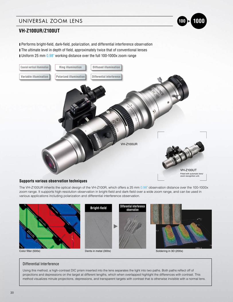
100 1000UNIVERSAL ZOOM LENS
VH-Z100UR/Z100UT
y Performs bright-field, dark-field, polarization, and differential interference observationy The ultimate level in depth of field, approximately twice that of conventional lensesy Uniform 25 mm 0.98" working distance over the full 100-1000x zoom range
Color filter (500x) Dents in metal (300x) Soldering in 3D (200x)
VH-Z100UR
VH-Z100UTFitted with automatic lens/zoom recognition unit.
Supports various observation techniques
The VH-Z100UR inherits the optical design of the VH-Z100R, which offers a 25 mm 0.98" observation distance over the 100-1000x zoom range. It supports high-resolution observation in bright-field and dark-field over a wide zoom range, and can be used in various applications including polarization and differential interference observation.
Differential Interference
Using this method, a high-contrast DIC prism inserted into the lens separates the light into two paths. Both paths reflect off of projections and depressions on the target at different lengths, which when overlapped highlight the differences with contrast. This method visualizes minute projections, depressions, and transparent targets with contrast that is otherwise invisible with a normal lens.
Bright-field Differential interference observation
Coaxial vertical illumination Ring illumination Diffused illumination
Polarized illuminationVariable illumination Differential interference

HIGH RESOLUTION RZ LENSES
21
ø2.3
6"ø6
082
.53.
25"
ø2.3
6"3.
25"
ø49.6ø1.95" ø1.95"
VH-Z100URNormal use
149 5.87"250.98" 0.98"
0.98" 3.78"
3.22"
0.69"
ø1.95"
5.87"
0.98" 4.24"
6.32" 3.22"
ø2.1
3"ø2
.36"
0.69"
1.31"
231 9.09"
ø60
82.5
ø49.6
With differential interference attachment
With differential interference attachment
Normal use
331.3" 160.5
6.32"25
242.59.55"
32.6
1.28
"
3.24
"
1.17
" 1.57
" 3.24
"
1.57
"
VH-Z100UT
(Observation distance)
(Observation distance) (Observation distance)
(Observation distance)
0.75"
ø60
82.4
ø54
4040
ø49.6ø1.95"
107.633.2
160.525 18.9
81.781.7
17.5
29.7
82.4
ø49.696149
25 19
ø54
ø60
ø2.3
6"ø2
.13"
17.5
0.74"
Reveals projections and depressions invisible with bright-field observation
The high-contrast DIC prism separates light into two paths that are reflected and made to interfere, making minute projections and depressions on the target clearly visible. This technique allows clear observation of scratches in metal or glass, and waviness or unevenness in film.
Bright-field (500x) Differential interference (500x)
ACF surface
Bright-field (200x) Differential interference (200x)
Magnetic tape
Using color to discern height differences
This technique combines an analyzer, polarizer, and λplate to cause changes in the phase of reflected light polarized onto the target. The changes in height appear as color, visually highlighting minute projections and depressions in the target.
Bright-field (300x) Differential interference (300x)
Cross-section of metal
Bright-field (150x) Differential interference (150x)
Solar cell
OPTIONS
Magnification 1 100x 200x 300x 500x 700x 1000x
Horizontal 3.050.12"
1.530.06"
1.020.04"
0.610.02"
0.440.02"
0.300.01"
Vertical 2.280.09"
1.140.04"
0.760.03"
0.460.02"
0.330.01"
0.230.01"
Diagonal 3.810.15"
1.900.07"
1.270.05"
0.760.03"
0.540.02"
0.380.01"
Working distance(mm inch)
25 (20 2) 0.98" (0.79 2)
1. Magnification on a 15-inch monitor.2. The Dual Light Base Unit (OP-84430) and the Adjustable Illumination (OP-72402) are attached.
LENS PERFORMANCE
Fiel
d-of
-vie
w(m
m in
ch)
DIMENSIONS Unit: mm inch
SCP filter set
OP-87821
DIC prism set
OP-86943
Fiber cables
OP-31207OP-51480
Variable illumination adapter
OP-72404
Ring illumination adapter
OP-72402
Diffuse illumination adapter
OP-87299
Contact adapter
OP-81880

22
250 2500DUAL LIGHT HIGH -MAGNIFICATION ZOOM LENS
VH-Z250R/Z250T
y Equipped with the Dual Light mechanism (quick changeover between bright-field and dark-field)y Capable of dark-field observation to a maximum 2500xy Uniform 6.5 mm 0.26" working distance over the full 250-2500x zoom range
Cross-section of photo film (250x) Bump (1000x) Probe dent (2000x)
VH-Z250R
VH-Z250TFitted with automatic lens/zoom recognition unit.
During observation, illumination for dark field and bright field can be easily switched
This lens incorporates dual illumination mechanisms: coaxial vertical illumination and ring illumination.
Dual Light
The dual light lens is a high magnification lens equipped with coaxial vertical illumination and standard-mounted ring illumination on the end. The 6.5 mm 0.26" observation distance enables dark-field observation, which is otherwise difficult at high magnification ranges due to the short observation distance to the target. The quick illumination changeover makes this particularly easy for anyone to use.
Polarized illuminationCoaxial vertical illumination Ring illumination

HIGH RESOLUTION RZ LENSES
23
6.50.25" 0.26"
2.52" 5.91"7.03"
11.38"0.75"
10.86"275.9
83 3.27"
60
3.01
"76
.5
ø502.
36"
ø1.97
"
124 69 2.72"150
4.88"5.91"
VH-Z250R VH-Z250T
(Observation distance)(Observation distance)
2.36
"
ø1.9
7"
6.5
56.5 74
.52.
93"
2.22
"
289
63.9 150178.6 19
60
ø50
ø72
ø2.8
3"ø2
.13"
ø54
Two lighting methods are integrated into the lens: coaxial vertical lighting and ring lighting. This eliminates the need for lens or light replacement and greatly reduces observation time.
Dual light
Bright-field Dark-field
Laser engraving (1000x)
Bright-field Dark-field
IC (500x)
OPTION
LENS PERFORMANCE
Fiel
d-of
-vie
w(m
m in
ch)
DIMENSIONS Unit: mm inch
Magnification 1 250x 300x 500x 1000x 1500x 2000x 2500x
Horizontal 1.220.05"
1.020.04"
0.610.02"
0.310.01"
0.20.01"
0.150.005"
0.120.004"
Vertical 0.920.04"
0.760.03"
0.460.02"
0.230.01"
0.150.005"
0.110.004"
0.090.003"
Diagonal 1.520.06"
1.270.05"
0.760.03"
0.380.01"
0.250.009"
0.190.007"
0.150.005"
Working distance(mm inch)
6.50.26"
1. When displayed on a standard 15-inch monitor.
Polarized illumination adapter
OP-51649

24
500 5000HIGH -RESOLUTION ZOOM LENS
VH-Z500R/Z500T
y Highest resolution in its class, 0.82 numerical aperturey Uniform 4.4 mm 0.17" working distance over the full 500-5000x zoom rangey Accepts polarized illuminations
TFT (5000x) Cell (2000x) Metal surface in 3D (500x)
VH-Z500R
VH-Z500TFitted with automatic lens/zoom recognition unit.
This zoom lens is the pinnacle of optical lenses
This zoom lens incorporates high-quality fluorite optics to provide the highest resolution in its class. The advanced 3D display function precisely reproduces images.
Numerical Aperture (N.A.)
The numerical aperture for the VH-Z500 Series is 0.82. Numerical aperture is often abbreviated as N.A. Its value indicates the brightness and resolution of the optical system. Numerical aperture is defined by N.A. = N sinθ (N: refractive index of the medium around the target/ N is 1 in air), where θ is the effective diameter of the lens that receives incident light from the target on the optical axis. When the observation medium is air, the closer the N.A. is to 1, the higher the resolution and sharper the image will appear.
Polarized illuminationCoaxial vertical illumination

HIGH RESOLUTION RZ LENSES
25
4.40.17"
60
2.83
"
ø2.8
3"ø2
.13"
2.83
"2.
20"
72
ø1.73
"ø4
4
276.5 10.89"
79.5 3.13" 4.88" 73 2.87"5.91"
124150
VH-Z500R VH-Z500T
(Observation distance)
2.36
"
2.36
"
(Observation distance)
ø1.7
3"
0.17"2.83" 5.91"
0.75"11.44"6.91"
4.4
ø44
7256
290.719
150
175.6
72
60
ø72
ø54
This adapter uses a half mirror to align the axis of light illuminated on the target with the optical axis of the lens. This increases the amount of regular reflection and is used for bright-field observation.
Coaxial vertical illumination
OPTIONS
LENS PERFORMANCE
Fiel
d-of
-vie
w(µ
m M
il)
DIMENSIONS Unit: mm inch
Magnification 1 500x 1000x 2000x 3000x 5000x
Horizontal 61024.02
30512.01
1525.98
1024.02
612.4
Vertical 45717.99
2299.02
1144.49
762.99
461.81
Diagonal 76230
38115
1917.52
1275
762.99
Working distance(mm inch)
4.40.17"
1. Magnification on a 15-inch monitor.
Fiber cables
OP-31207OP-51480
Polarized illumination adapter
OP-51649

26
50 500LONG-FOCAL-DISTANCE, HIGH-PERFORMANCE ZOOM LENS
VH-Z50L/Z50T
y 85 mm 3.35" observation distance at up to 500x zoomy 50x to 500x optical 10x zoom lensy Deep depth of field, approximately three times that of conventional lenses
Metal surface (300x) Cross-section of a BGA (500x)
VH-Z50L
VH-Z50TFitted with automatic lens/zoom recognition unit.
Long Range Lens with a 85 mm 3.35" Working Distance
This lens uses cutting-edge optical design and advanced illumination technology to maintain an 85 mm 3.35" observation distance even at the maximum 500x magnification. It can capture recesses in the target clearly and it offers ample working space for dramatically improved observation efficiency.
Long Working Distance
The VH-Z50 Series has an observation distance of 85 mm 3.35" at 500x magnification. Thanks to a sophisticated lens design, this lens allows distant targets to be observed in high-magnification, inconceivable with conventional optical microscopy. By coupling a large diameter objective lens with advanced assembly techniques and the latest in illumination technology, the VH-Z50L achieves three times the depth of field of conventional lenses, well beyond the limits of the conventional microscope.
Polarized illumination
Coaxial vertical illumination Ring illumination Diffused illumination

LONG DISTANCE LW LENSES
27
8.8"
6.12"
223.5
155.5853.34"
VH-Z50L VH-Z50T
ø49
ø1.93
"
ø49.6
ø1.95
"ø6
0ø2.
36" 2.
34"
59.5
160.63"
75.5
2.97
"
(Observation distance)
56.5
74.5
6.5289
63.9 150178.6 19
60
(Observation distance)
0.26"
2.52"
ø72ø54
ø50 ø2
.83"
ø1.9
7"
ø2.13
"
2.36
"
2.22
"2.
93"
0.75"11.38"
7.03"5.91"
Z50L/T OPTICAL ADAPTER
IC (500x)
RING I LLUMINATION971927
Soldering (200x)
DIFFUSE I LLUMINATION971929
POLARIZED I LLUMINATION971930
Plastic gate section (50x)
OPTIONS
LENS PERFORMANCE
Fiel
d-of
-vie
w(m
m in
ch)
DIMENSIONSMagnification 1 50x 100x 200x 300x 400x 500x
Horizontal 6.090.24"
3.050.12"
1.530.06"
1.020.04"
0.760.03"
0.610.02"
Vertical 4.570.18"
2.280.09"
1.140.04"
0.760.03"
0.570.02"
0.460.02"
Diagonal 7.620.30"
3.810.15"
1.900.07"
1.270.05"
0.950.04"
0.760.03"
Working distance(mm inch)
85.03.35"
1. Magnification on a 15-inch monitor.
Polarized illumination971930
Diffuse illumination971929
Ring illumination971927
971928
Fiber cables
OP-31207OP-51480
Polarized illumination adapter
OP-72406OP-72407

28
35 245
150 800
LONG-FOCAL-DISTANCE ZOOM LENS
VH-Z35
OPTION
LENS PERFORMANCEMagnification 1 35x 50x 100x 150x 200x 245x
Horizontal 8.710.34"
6.100.24"
3.050.12"
2.030.08"
1.530.06"
1.240.04"
Vertical 6.500.26"
4.550.18"
2.280.09"
1.520.05"
1.140.04"
0.930.04"
Diagonal 10.890.43"
7.620.3"
3.810.15"
2.540.1"
1.900.07"
1.560.06"
Depth of field(mm inch)
8.30.33"
5.00.2"
1.00.04"
0.50.02"
0.40.02"
0.30.01"
Working distance(mm inch)
54.02.13"
1. Magnification on a 15-inch monitor.
MIDDLE-RANGE ZOOM LENS
VH-Z150
OPTION
LENS PERFORMANCEMagnification 1 150x 200x 500x 800x
Horizontal 2.030.07"
1.530.06"
0.610.02"
0.380.014"
Vertical 1.520.06"
1.140.04"
0.460.02"
0.280.011"
Diagonal 2.540.1"
1.900.07"
0.760.03"
0.480.018"
Working distance(mm inch)
12.0 0.47" 2
1. Magnification on a 15-inch monitor.2. 6.5 mm 0.25" when the coaxial vertical illumination ring is attached.
With a observation distance of 54 mm 2.13" and extremely large depth-of-field, this lens provides a convenient way to monitor a target with height differences on the surface and greatly increases monitoring efficiency. With a single lens, you can view from a low magnification (35x) to a high magnification (245x), allowing the desired point to be quickly enlarged.
35x to 245x magnification at a distance of 54 mm 2.13"
This middle-range zoom lens allows continuous changes in magnification of between 150x and 800x. It can be used to monitor at a distance 12 mm 0.47" at 800x magnification. The illumination head can be switched to a coaxial vertical illumination type to enable detailed observation of microstructure of metal or a semiconductor surface.
150x to 800x magnification, ideal for monitoring reflective surfaces
Adjustable illumination adapter
Coaxial vertical illumination adapter
OP-35416
Adjustable illumination adapter
VH-K150
Fiel
d-of
-vie
w(m
m in
ch)
Fiel
d-of
-vie
w(m
m in
ch)

29
Double the brightness than conventional modelsIt becomes possible to switch from a direct view to a lateral view by installing the 90° lateral view tube on the borescope lens. The extensive lineup of five types, ø1.8, ø2.7, ø4, ø5.5, ø10, allows for the most suitable selection of the borescope according to the application.In addition, the Borescope Lens Zoom Attachment has a 3x optical zoom mechanism which produces observation with higher resolution.
FIBERSCOPE
VH-F61/F111
Monitoring a complicated shapeThe fiberscope allows you to monitor places where conventional lenses cannot be used, such as the inside of a complicated machine or a narrow, bending pipe. You can even monitor blind spots by changing the angle of the tip of the fiberscope remotely.
VH-F111
VH-F61
Inspecting pipes
Inspecting the inside of a photocopier
BORESCOPE LENS
VH-B18/B27/B40/B55/B100
VH-BA
VH-B18
NEW
VH-B27
VH-B40 VH-B55
VH-B100
Borescope VH-B18 VH-B27 VH-B40 VH-B55 VH-B100Lens attachment VH-BA
Outer diameter 1 (mm inch)
ø1.8 (ø2.0) ø0.07"
(ø0.08")
ø2.0 5
ø0.08"
ø2.7(ø3.0)ø0.11"
(ø0.12")
ø3.0 5
ø0.12"ø4.0
ø0.16"ø4.4 5
ø0.17"ø5.5
ø0.22"ø5.9 5
ø0.23"ø10.0ø0.39"
ø10.5 5
ø0.41"
Effective length (mm inch) 95 3.74" 185.3 7.30" 141.5 5.57" 276 10.87" 276 10.87"
View direction 2
Direct view 0° 0° 0° 0° 0°Lateral view 90° 90° 90° 90° 90°
View angle 30° 32° 30° 35° 35°
Working distance (mm inch)
3 or more0.12" or more
3 or more0.12" or more
5 or more0.20" or more
5 or more0.20" or more
3 or more0.12" or more
Maximum observationmagnification 3 360x 150x 140x 125x 135x
Minimum view range (mm inch) 4 0.8 0.03" 2 0.08" 2 0.08" 2.4 0.09" 2.2 0.09"
Ambient temperature 0 to 40°C 32 to 104°F
1. The value in parenthesis is when the Guard tube is installed. 2. 0°: When the borescope lens alone/With the Guard tube installed, 90°: When the Lateral view tube is installed3. The magnification at around the center of a 15-inch monitor. 4. Horizontal view angle5. The value is when the Lateral tube is installed.
Mod
el
Borescope VH-F61 VH-F111Lens attachment VH-F
Outer diameter (mm inch) ø6.1 ø0.24" ø11 ø0.43"Effective length (mm inch) 1000 39.37" 1500 59.06"
View direction Direct viewView angle 65° 55°
Observation depth (mm inch)
10 to ∞0.39" to ∞
20 to ∞0.79" to ∞
Bendable sleeve angle 120° up/down 120° up/down, 100° right/left
Ambient temperature 10 to 80°C 50 to 176°FOperating atmospheric
pressure 1 atm
Oil & waterproof Machine oil and light oil
Mod
el

30
Easy-to-adjust
45°
60°
60°
90°
75°
45°
45°
30°
15°15°
30°
0°
0°
45°
90°
Cable holder
High-stability frame
Oblique axis
Rotation axis
Vibration-proof rubber
Secures camera/lighting cables to prevent vibration. The cables are also protected against abrasions and deterioration.
0°
90°60°
120°
Faster Z-Axis MovementThe maximum speed of the motorized Z-axis stage has increased to 17 mm 0.67”/sec. This significantly improves the auto-focus and depth composition speeds.
Improved Vibation ResistanceBy using an aluminum die-cast frame for the stand, vibration-resistance has increased twofold over previous models.
Better Viewing RepeatabilityA new locking mechanism has been incorporated into the stand to ensure that the lens is set to 0 degrees.
Built-In Tilt Angle SensorA built-in sensor detects the tilt angle of the stand. Now it is possible to display the angle on the observation screen or to save the condition during recording.
FREE-ANGLE OBSERVATION SYSTEM (XYZ MOTORIZED)
VHX-S550E
This versatile stand includes XY and Z axes controls for adjusting position and focus, and the stage can be rotated freely. A custom mechanism allows the camera and lens to be tilted around the object being viewed, while still keeping that object perfectly centered in the field-of-view.
31
3-Axis Rotation Mechanism
Stability
Vibration-Proof Rubber
Anti-Vibration System
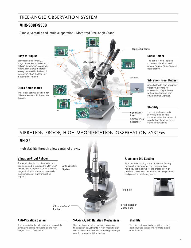
Easy-to-AdjustEasy focus adjustment, X-Y stage movement, rotation and oblique axis motion. A custom mechanism allows the target to stay centered in the field of view, even when the lens unit is inclined or rotated.
Quick Setup MarksThe ideal setting position for different lenses is indicated on the arm.
Cable HolderThe cable is held in place to prevent vibrations and protect against abrasions and deterioration.
3-Axis (X/Y/θ) Rotation Mechanism This mechanism helps everyone to perform fine position adjustments in high-magnification observations. Furthermore, removing the stage enables transmitted illumination.
Anti-Vibration SystemThe cable is tightly held in place, completely eliminating subtle vibrations during high-magnification observation.
Vibration-Proof RubberA special vibration proof material has been selected to insulate the VHX-S50/VH-S5. It is designed to absorb a broad range of vibrations in order to provide stable images of highly magnified objects.
StabilityThe die-cast main body provides a highly rigid structure that allows for more stable observations.
Aluminum Die CastingAluminum die casting is the process of forcing molten aluminum under high pressure into mold cavities. It allows for the creation of high precision casts, such as automotive components and precision machinery parts.
StabilityThe die-cast main body provides a highly rigid structure with a low center of gravity that allows for more stable observations.
60°
60°
90°
75°
45°
45°
30°
15°15°
30°
0° Quick Setup Marks
Easy-to-Adjust
Cable Holder
High-stability frame
Vibration-Proof Rubber Feet
Oblique axis
Angle
Rotation axis
45°
0°
45°
90°
0°90°
60°
120°
Vibration-Proof RubberAbsorbs low to high frequency vibration, allowing for observation of specimens without interference from environmental vibration.
FREE-ANGLE OBSERVATION SYSTEM
VHX-S30F/S30B
Simple, versatile and intuitive operation - Motorized Free-Angle Stand
VIBRATION-PROOF, HIGH -MAGNIFICATION OBSERVATION SYSTEM
VH-S5
High stability through a low center of gravity

32
All-in-one 3D profile measurement system including a precision motorized stage for 3D measurement
The precision linear stage and newly-developed shape measurement functions allow integrated operation of magnified observation and automatic 3D shape measurement. All of the steps from stage operation, magnified observation, 3D analysis to image saving can be controlled with the VHX unit. This integration significantly reduces image capture and analysis time.
ControllerVHX-S15CE
Vibration-resistant, high-magnification observation systemVH-S5
Free-angle observation systemVH-S30
Electric stageVHX-S15H
Electric stageVHX-S15F
Easy, on-screen 3D profile measurement*
The VHX Series creates a 3D image based on automatically captured images, and it calculates height profile data on a desired measuring line. Height, width and height difference data on the measuring line are plotted on a graph. Since the profile graph is related to the cursor position in the image display area, you can see the current measuring point easily.*The function of optional measurement software.
Color topographical overlay allows you to see height differences at a glance*
Color bars that indicate height are displayed on a 3D image. The highest position is displayed in red, and the lowest position is displayed in blue, allowing you to see a height difference at a glance. The height data can be superimposed on a raw image. Furthermore, the X-axis, Y-axis and Z-axis scales are calculated automatically and displayed according to the image size and the 3D rotation angle.*The function of optional measurement software.
Electronic die component (500x)
3D PROFILE AUTOMATIC MEASUREMENT UNIT
VHX-S15 Series
OPTIONSPECIFICATIONSModel VHX-S15CE/H (VHX-S15F) 2.
Stage stroke distance 15 mm 0.59"
Motor 5-phase stepping motorResolution 0.05 μm 0.002 mil/pulsePositioning accuracy 1. 6 μm 0.23 milRepeatability 1. ±0.5 μm ±0.02 mil
RatingsPower supply voltage 100 to 240 VAC, 50/60 HzPower consumption 70 VA
Ambient temperature 5 to 40°C 41 to 104°FRelative humidity 35 to 80%, No condensation
Weight VHX-S15CE (Controller): 3 kg, VHX-S15H (Electric stage): 1.3 kg, VHX-S15F (Electric stage): 3.2 kg
Load capacity 5 kg
1. Positioning accuracy and repeatability specifications apply to the motorized stage2. The motorized stage for the VH-S30 is the VHX-S15F.
Digital indicator set
OP-51610
Digital indicator for direct measurement of the lens stroke distance, ensuring easy calibration.
3D raw image
Electronic die component (500x)
3D raw image + Topographic imageWith the horizontal/vertical cursor, the height and width can be measured. The 2-line comparative mode can simultaneously display comparative analysis profile data on two parallel lines.
3D topographic image

33
The Measuring Microscope System for measuring with fine precision on all microscopes
XY MEASUREMENT SYSTEM
VH-M100 Series
Stage meets traceability requirements of international standards
Measures over long strokes with fine precision. The stage travel can also be calibrated, just like stages for conventional measuring microscopes.
Measurement range of 100 x 100 mm 3.94" x 3.94" measures large workpieces
The VH-M100 measures the travel of the work-mounted stage as it moves by turning X and Y handles. Large workpieces that were outside the view of conventional microscopes can also be measured.
X-Y measurement systemVH-M100E
SPECIFICATIONSModel VH-M100E
Stage stroke distance 100 mm (3.94") in the X and Y directions, respectively
Display resolution 0.1 μmMovement accuracy 4 + 0.02L (μm)*
RatingsPower supply voltage 100 to 240 VAC 50/60 HzCurrent consumption 50 VA
Environmental resistance
Ambient temperature 5 to 40°C 41 to 104°FRelative humidity 35 to 80%, No condensation
Weight 18 kgLoad capacity 3 kg
* “L” means movement distance (mm).
Transmission illumination unitOP-84484Clearly projects edges of a target.
OPTION
Display unitOP-84483The display unit is useful when the moved distance cannot be confirmed on the monitor.
For the VH-M100 Lens holder(For manual low-power zoom)
OP-84486
For the VH-M100Lens holder(For manual high-power zoom)
OP-84487
Lens holder for the VH-M100(For motorized zoom)
OP-84488

34
Telephoto Normal Wide-angle
Focal length
Observation distance
Far-point length
Depth of fieldNear-point length
LENS KNOWLEDGE 1 LENS INFORMATION
ZOOM LENS
A zoom lens allows for fast observation as the magnification can be adjusted by simply rotating a zoom ring. A typical microscope is equipped with only 3 to 4 different lenses to choose from, but a zoom lens can be gradually adjusted from low to high magnification. It is more compact and less costly
than using several lenses.
Operation of a Zoom Lens
In optical discussions, a single lens is called a "simple lens", while a lens designed with added functionality using multiple lenses is called a "compound lens". KEYENCE lenses are made of complex lenses using sophisticated lens design technology to dramatically increase their functionality. In a zoom lens, the distance between each constituent lens is changed to alter the focal length which, in turn, makes the lens wide-angle or telephoto.
Focal Length and Working distance
The focal length refers to the distance between the target and the lens when the lens is in focus and the target appears clearest. Observation distance, also known as working distance (WD), refers to the distance from the tip of the lens (including lighting adapters, etc.) to the target. Observation distance is slightly shorter than the focal length. Accordingly, more attention is paid to observation distance in a lens
specification.
Depth of Field
When observing an object with a lens, the object is most clearly observed when it is at the focal position of the lens. If the distance between the object and the lens is slightly changed, it can still be clearly observed within a tolerance area. The tolerance within which the object is in focus is called the depth-of-field. A lens with large tolerance has a large depth-of-field and a lens with little tolerance has a shallow depth-of-field. When using a lens with a large depth-of-field, it is possible to precisely and quickly observe an entire object with projections and depressions.
Design of a zoom lens
Focal length and observation distance
Diagram of depth of field

35
Standard position
Zoom lenses
CCD
Back focus is inconsistentCCD position is farther than the designed focal point of the lens
CCD position is closer than the designed focal point of the lens
Image appears smaller than the actual magnification.
Image appears larger than the actual magnification.
Back Focus
Back focus refers to the distance from the surface of the camera to the focal point of the optical lens. The back focus on all KEYENCE zoom lenses is designed to be a fixed length. Therefore, it is possible to always observe at the same working distance and magnification reference, saving time and eliminating measurement errors caused by back focus.
Optical Aberration
The image formed by light that actually passes through the lens differs slightly from the ideal image. This difference is called aberration. Aberration causes the image to form at a different point which can impart coloration to the image or blur the color of the image. The image may develop a tail that extends from the axis of light or it may appear distorted. As such, the less aberration a lens has, the better it is considered to be. Aberration is commonly more pronounced at the periphery than at the center. While it is not possible to completely eliminate aberration, it is possible to reduce degradation of the picture quality by using a combination of multiple lenses made of materials with properties to cancel the effects of aberration.
Chromatic Aberration
White colored light is a combination of various colors. When light passes through a lens, the refractive index of each color in the light differs, thus causing different convergence positions. This effect is called chromatic aberration. A lens with chromatic aberration will cause the colors away from the center of the screen to bleed.
Chart image when there is chromatic aberration (Image for reference purposes only)
To reduce chromatic aberration, a convex lens that has a low refractive index for color can be used with a concave lens that has a high refractive index for color, or a combination of multiple lenses made from different materials can be used.
Focal point

36
Effective diameter
N.A.0.61λ
Distribution of point image intensity
Light intensity
Distance
Airy disk
Radius of Airy disk r =
r
θ' θ
On the object sideN.A.=n sin θ'
On the objective lense sideN.A.=n sin θ
LENS KNOWLEDGE 2 LENS INFORMATION
Fluorite Lens
Lenses are commonly made from optical glass, a type of glass that has a uniform refractive index and low light absorption. In addition to glass, natural elements such as crystal may be used. There are various types of crystal, with fluorite (CaF2) considered particularly suitable for lens-making.
Crystal/quartz (Sio2)Crystal is a quartz with a high crystalline structure. It is colorless and transparent, and light passes through it easily. Today, it can be made through artificial means and is actually used to make optical fiber.
Fluorite (CaF2)Fluorite is characterized by its ability to pass light of long wavelengths, and is good at passing light from ultra-violet to infra-red. Although it is ideal for lens-making, fluorite is relatively expensive due to its rarity and processing difficulty.
Halite (NaCl), Silicon (Si), Germanium (Ge)These elements pass infra-red rays well, and are traditionally used in infra-red equipment designed to analyze matter.
When fluorite is made into a lens, it removes residual chromatic aberration (secondary spectrum) which is what disturbs the sharpness in a captured image. Compared to an optical glass lens, the refractive index is lower so the lens has extremely low dispersion.
Numerical Aperture (N.A.)
Often abbreviated as "N.A.", its value indicates the brightness and resolution of the optical system. Numerical aperture is defined as follows:
NA = n sin θ
where N is the refractive index of the medium around the target (N = 1 in air)
Light exhibits a wave-like spreading ef fect known as diffraction. This is what causes it to spread in a disk-shaped pattern rather than converging at a single point even when a high-performance lens with no aberration is used. Numerical aperture indicates the light-condensing limit or diffraction limit of a lens without optical aberration, a concept thought to come from light's wave-like behavior. This disk-shaped wave is called an Airy disk. The radius r (width) of an Airy disk is calculated using the formula below.
r = 0.61λ/N.A.(λ: wavelength of light, N.A.: numerical aperture, 0.61: constant)
The value derived using this formula is called "resolution". Based on this formula, the larger the numerical aperture the smaller the radius of the Airy disk, which implies that a larger numerical aperture will produce a sharper image. This is a common criterion used to evaluate lenses.
Figure defining numerical aperture

37
2 3 4 5 8 9
LENS PRODUCTION
It takes many steps to produce a lens product. Polishing is not
the only factor that determines the performance and quality of
a lens. Rather, it is the culmination of each step taken to make
the lens. This is why all KEYENCE lenses are made using an
integrated process.
1. Optical and Mechanical Design
The lens system, from simple lenses to compound lenses, is assembled using computer simulation. The mechanical design for the lens tube and zoom mechanism is made to match the lens system. To produce a lens that meets the level of sophistication afforded by computer-based optical designs, polishing, machining, and assembly technology is also required.
2. Optical Glass Material
Most optical glasses are cylindrical before grinding. The cylinder is sliced into disks and then goes through a machining process. The KEYENCE RZ lens uses materials with various optical properties, each designed to contribute to forming an ideal image. The optical glass still lacks transparency at this stage.
3. Rough Cut
This process cuts the glass disks into lens blanks. Machines such as the Oscar grinder and curve generators are used to grind the lens to its rough radius of curvature, dimension, and shape. The Oscar grinder uses a polishing disk made by pouring coal tar, called pitch, on the polishing plate. At this stage, the lens still has a frosted appearance.
4. Grinding Using Pellets and Resin
Pellets are abrasive grains made of diamonds that are implanted on a small, thin, disk-shaped grindstone. Several of these grindstones are cemented to the disk to polish the lens. Next, a resin grindstone is used to polish the lens further.
5. Polishing
This process uses an abrasive to polish the sur face of the lens more delicately. The lens is f inished by repeatedly polishing and checking the mirror surface finish. The finished lens will be clear after this process. The most important point during lens polishing is, in addition to the abrasive, the use of temperature-controlled water. Failure to keep the water at the optimum temperature will result in a lens surface that does not meet the design specifications. The surface finish is measured using an interferometer.
6. Cleaning
After the polishing process is done, the lens is put through an ultrasonic cleaner to remove abrasives and other matter.
7. Centering
This is the final polishing stage. The center of the lens is clamped in the cutting machine and spun at high speed while the periphery is ground so that the optical axis centers in the lens.
8. Coating
The lens is coated to prevent diffuse reflection and improve light transmittance. A vacuum depositor located in the clean room is used to deposit the coating on the lens. This treatment is what makes the lens transmit only light of a fixed wavelength.
9. Assembly
The completed lenses are now assembled in a clean room into a single lens by one technician. To ensure the lens resolves highly from low to high magnification, not only must each lens be precision-made, they must also be assembled with precise skill to ensure they are concentric and free of play when zoomed.
10. Final Inspection
The lens must pass more than 20 final inspection tests before it can be shipped as an "RZ Lens".

www.keyence.com
VHLens&StandV5-KA-C-US 1075-1 611A96 Printed in JapanCopyright (c) 2015 KEYENCE CORPORATION. All rights reserved. * 6 1 1 A 9 6 *
The New Standard for Microscopes
DIGITAL MICROSCOPEVHX-5000
❙ All-in-one microscope that incorporates observation, image capture and measurement capabilities❙ Depth-of-field 20 times greater than optical microscopes❙ Motorized XYZ controls for simplified operation❙ Instantly view any area entirely in focus❙ Intuitive user interface allows everyone to perform analysis easily❙ Advanced 2D and automated area measurement functions