telorvek efi 4.6 sequential fuel injection system … efi 4.6 sequential fuel injection system ......
TRANSCRIPT
Page #1
TELORVEK EFI4.6 Sequential Fuel Injection
System (FT-95A)
WIRING INSTRUCTIONS
Thank you for purchasing the absolute finest of wiring kits for the Ford Motor Co. 4.6 94-96 fuel injection
engine. W e have taken considerable time to work out the circuitry so that you, the customer will
understand at least some of what this is all about. W e ask that you follow our instructions closely. You
must use a high pressure in tank fuel pump. Custom installations are available from Tanks Inc. (320-558-
6882) and Rock Valley (800-344-1934).
Should you eliminate any sensor, your injection system will not work at its peak and will probably be in
some variation of back up mode. There are many factors that will help you get a trouble free start up that
you must consider.
NOTE: FORD diagnostic procedures are very detailed, lengthy and impossible tocover in this set of instructions. Purchasing the FORD ENGINE/ EMISSIONSDIAGNOSIS shop manual will help you learn about the engine you installed and guideyou through the correct diagnostic procedures Ford recommends. This book isavailable through your local Ford dealer or Helm Inc. Helm is the distributor forthe shop manuals for General Motors and Ford Motor Company. Helm can becontacted at 800-782-4356 or on their web site www.helminc.com
WARNING!After the kit installation is complete and it is necessary to diagnose a startingor drive ability problem, follow the procedures recommended in the shopmanual. All voltage tests must be preformed using a HIGH impedance, digitalvoltmeter. DO NOT use a test light on this system! DAMAGE WILL BE DONEto the engine computer if a test light is used on this system.
STARTING INSTALLATION
Since there are so many individual circuits to complete, we recommend that you connect them in
the order that we prescribe. Disconnect the battery before starting and do not reconnect until
instructed.
Page #2
There will be many connections to the TELORVEK panel so plan the location of the panel in an
area with room to work. We suggest mounting the panel in an assessable location, in the trunk,
under the seat or under the dash are good. In order to allow for the proper spacing between the
computer and the Telorvek panel, plug the connector into the computer (ECM) and mount the
panel and computer. For safety, disconnect the ECM connector until finished the installation. A
poor installation will result in a poor running car. The number referred to from this point on will
be the location on one of the terminal blocks located on the TELORVEK panel.
After all wires are connected to the engine, wire tie them together or use 3/4 inch Zip loom to
protect them. This can be done before any connections are made to the panel. Since all wires are
marked, running the entire group to the panel at one time is fine. Some terminals on the panel may
not be used!
*******Important! We have supplied three sizes of terminals for your use on the panels itself. The Yellow
is for 10-12 gauge wire, Blue for 14-16 gauge wire and red for 18 gauge wire. Each individual bag
instructions will be marked as to which terminal to use.
L NOTE 7You will be moving around to different terminals on the TELORVEK panel tomake connections. For this reason extra care is needed when making allconnections to the panel.
Bag #60. INJECTORS: The injector wiring is made up in two harnesses, one for the left bank of injectors
and one for the right bank. Locate the right injector connector with the Red and Tan wires and connect it to
cylinder number (1) injector one. Now plug in the rest of the injector connectors (injectors 2, 3, 4) in that
half of the harness. In the left injector harness locate the injector connector with the Red and Black wires
and connect it to injector number (5). Plug in the rest of the injector connectors (injectors 6, 7, 8) and run
all the wires from both haves of the harness to the Telorvek Panel. Using the blue terminals connect the
Red wires (INJ 1->4) and (INJ 5->4) to #4. Now connect the remaining eight wires as follows using the red
terminals, Tan (INJ 1->64) to #64, W hite (INJ 2->65) to #65, Brown (INJ 3->66) to #66, Lt Blue (INJ 4->67)
to #67, Black (INJ 5->68) to #68, Lt Green (INJ 6->69) to #69, Dk Blue (INJ 7->70) to #70 and Dk Green
(INJ 8->71) to #71.
Bag #61. IGNITION COIL: The 4.6 engine has two coil packs, one for the left spark plugs and one for the
right spark plugs. The coil packs are mounted to each head in front of the engine. The left coil pack
connector has Red, Tan and Lt Blue wires and the right coil pack connector has Red, W hite and Orange
wires. After attaching the connectors to the coils run the wires back to the Telorvek panel. Connect the
Red wires (LF IGN COIL->10) and (RT IGN COIL->10) using the blue terminals to #10. Using the red
terminals connect the Tan (LF IGN COIL->12) to #12, Lt Blue (LF IGN COIL->13) to #13, W hite (RT IGN
COIL->14) to #14 and the Orange wire (RT IGN COIL->15) to #15.
Bag #62. IGNITION CONTROL MODULE CONNECTION: The ICM requires some of the wires to be
shielded from any electrical interference, that is why seven of the wires (Pink, Gray, Purple, Dk Blue, Dk
Green, Solid Strand) in the connector are wrapped.
Carefully uncoil the harness and plug it into the ICM then run all the wires to the Telorvek panel. Remove
the tape and shielding material back only as far as it is necessary for the length of the wire to be cut and
allowing enough wire to make the connections on the panel. In the shielded harness there is two solid
strand wires with no insulation, install a blue terminal on them and connect one to #27 and the other to
#28. After the connection is made wrap the exposed wires from the shielded harness to #27 and #28 with
electrical tape. Using red terminals, the other five wires in the shielded harnesses are connected as
follows, Pink (ICM 3->16) to #16, Gray (ICM 1->17) to #17, Purple (ICM 7->18) to #18, Dk Blue (ICM 5-
>19 to #19 and the Dk Green (ICM 4->20) to #20.
Page #3
Connect the seven remaining wires running from the ICM connector as follows: Red (ICM 6->7) to #7,
Purple (ICM 2->11) to #11, Tan (ICM 11->12) to #12, Lt Blue (ICM 12->13) to #13, W hite (ICM 8->14) to
#14, Orange (ICM 9->15) to #15 and Black (ICM 10->24) to #24.
If desired a tach can be wired into the system by connecting the purple wire (11->TACH) to #11
on the panel and run it to the tach.
WARNING !!!The distributorless ignition system (DIS) on this engine is a high energysystem operating in a dangerous voltage range which could prove to be fatal ifexposed terminals or live parts are contacted. Use extreme caution whenworking on the vehicle with the ignition on or the engine running.
Bag #63 CRANK POSITION SENSOR (CPS) : Requires the wires to be shielded from any electrical
interference. Carefully uncoil the harness and plug it into the CPS located on the right front of the engine.
Run the wires to the Telorvek panel. Remove the tape and shielding material back only as far as it is
necessary for the length of the wire to be cut and allowing enough wire to make the connections on the
panel. In the shielded harness there is a solid strand wire with no insulation, install a blue terminal on it
and connect it to #27. After the connection is made wrap the exposed wire from the shielded harness to
#27 with electrical tape. Connect the remaining two wires as follows: Dk Blue (CPS->19) to #19 and the
Dk Green wire (CPS->20 to #20.
Bag #64. MASS AIR FLOW SENSOR: Attach the connector to the M.A.F sensor located in the air intake
tube between the intake manifold and air cleaner. Using a blue terminal run the Red wire (MAF->7) to #7.
Now using the red terminals run the Black (MAF->25) to #25, Tan (MAF->22) to #22 and the Lt Blue
(MAF->21) to #21
Bag #65. CAM SHAFT SENSOR: Requires the wires to be shielded from any electrical interference.
Carefully uncoil the harness and plug it into the sensor located on the left front of the engine. Run the
wires to the Telorvek panel. Remove the tape and shielding material back only as far as it is necessary for
the length of the wire to be cut and allowing enough wire to make the connections on the panel. In the
shielded harness there is a solid strand wire with no insulation, install a blue terminal on it and connect it
to #24. After the connection is made wrap the exposed wire from the shielded harness to #24 with
electrical tape. Connect the remaining two wires as follows: Dk Blue (CAM SENSOR->23) to #23 and the
Gray (CAM SENSOR->74) to #74.
Bag #66. ENGINE COOLANT TEMPERATURE SENSOR: After attaching the plug to the sensor located
on the lower front of the engine, near the alternator run the two wires to the panel. Connect them using the
red terminals, Lt Green wire (ECT->35) to #35 and the Gray wire (ECT->72) to #72.
Bag #67. THROTTLE POSITION SENSOR (TPS): Plug into the sensor located in the rear of the engine
on the throttle body and run the wires back to the panel. Using the red terminals run the Brown (TPS->37)
to #37, W hite (TPS->36) to #36 and Gray (TPS->72) to #72.
Bag #68. EXHAUST GAS RECIRCULATION VALVE POSITION SENSOR & EGR SOLENOID: Plug in
the connector to the EGRVP located on the rear of the engine. Using red terminals run the Lt Green wire
(EGRVP->38) to #38, Brown wire (EGRVP->37) to #37 and the Gray (EGRVP->73) to #73.
Plug the connector into the EGR solenoid located on the rear of the engine. Using a the red terminals run
the Red wire (EGR SOL->5) to #5 and the Brown wire (EGR SOL->39) to #39.
Page #4
Bag #69. INTAKE AIR TEMPERATURE SENSOR (IAT): Plug the connector onto the IAT sensor located
in the air intake tube. Run the wires to the Telorvek Panel and using the red terminals connect the Yellow
wire (IAT->40) to #40 and the Gray wire (IAT->74) to #74.
Bag #70A. OXYGEN SENSOR (4): This area of the vehicle is hot so keep the wires away from the
exhaust. Four sensors are required per engine. NOTE: If you are using headers, two of the O2 sensors
should be mounted in the collectors and the other two in the exhaust pipes behind the catalytic converters.
Mount the heated O2 sensors in the exhaust as follows:
LF O2 #1: Mounts in the left exhaust manifold or header collector.
RT O2 #1: Mounts in the right exhaust manifold or header collector.
LF O2 #2: Mounts in the left exhaust pipe behind the catalytic converter.
RT O2 #2: Mounts in the right exhaust pipe behind the catalytic converter.
The O2 sensors must reach a certain temperature before they will produce a signal.
Plug in the connectors into the O2 sensors following the wording printed on the wires and run the wires to
the Telorvek panel. Using the blue terminals connect the Orange wires (LF 02 1->8) and (RT O2 1->8) to
#8 and the Orange wires (LF O2 2->9) and (RT O2 2->9) wires to #9. Connect the Gray wires from the
sensors (LF O2 1->76),(RT O2 1->76) to #76 and the Gray wires (LF O2 2->77), (RT O2 2->77) to #77.
Now using the red terminals connect the Dark Blue (LF O2 1->43) to #43, Yellow (LF O2 1->44) to #44,
Light Blue (RT O2 1->41) to #41, W hite (RT O2 1->42) to #42, Light Green (RT O2 2->45) to #45, Black
(RT O2 2->46) to #46, Tan (LF O2 2->48) to #48 and Pink (LF O2 2->47) to #47.
Bag #71. IDLE SPEED CONTROL: The ISC is located on the rear of the engine in the throttle body. Plug
in the connector and run the wires back to the panel. Using the red terminals, connect the W hite wire
(ISC->56) to #56 and the Red wire (ISC->6) to #6.
Bag #72. DATA LINK CONNECTOR: Mount the connector inside the vehicle under the dash and run the
wires to the Telorvek Panel. Using the red terminals connect the Yellow (DLC 16->97) to #97, Purple
(DLC 13->54) to #54, Pink (DLC 10->52) to #52, Black (DLC 5->26) to #26, Black (DLC 4->26) to #26 and
the Light Blue (DLC 2->53) to #53.
The remaining Lt Green & Red wires are for the dash mounted service engine soon (S.E.S) light. The
light must be a two wire un-grounded light. Connect the Lt Green wire (55->SES LT) to #55 on the
Telorvek Panel and run it to a dash indicator light and connect it to one of the wires running from the light.
The red wire (92->SES LT) connects to #92 on the panel and run to the other wire running from the light.
This light is not required as the yellow light on top of the Telorvek Panel has the same function.
Bag #73 OCTANE ADJUST: The ECM measures voltage across the octane adjust connector and uses
this information to modify ignition spark advance. Leave this connector plugged together but if you
experience detonation while driving, un-plug this connector or use higher octane gasoline. Using the red
terminals, connect the Gray (OCTA ADJ->78) to #78 and the Dk Green (OCTA ADJ->57) to #57.
Bag #74 NOT USED IN THIS APPLICATION.
Bag #75A RADIATOR COOLING FAN: Mounted in the cover of the Telorvek panel is the cooling fan
relay connector. This connector is the second connector down from the top. You must install a GM relay
(part #14100455) into the connector or the electric cooling fan W ILL NOT operate.
Connect the Brown wire (102->COOLING FAN) to #102 on the panel and connect it to the electric cooling
fan positive terminal. A ground wire must be added to the negative terminal on the fan and run to a good
ground.
Fan relay socket requires Airtex part number 1R1061 or Standard Motor Products RY116 or our
part number HR-3.
Page #5
Bag #76 FUEL PUMP, FUEL PUMP RELAY & INERTIA SWITCH: W e have included the wiring
necessary for the Ford inertia switch. The inertia switch cuts off the electric fuel pump in the advent of an
accident. Mount the inertia switch in the rear of the vehicle in a dry area. Using the blue terminals, plug the
connector into the inertia switch and run the Tan wire (INERTIA->104) to #104 on the Telorvek panel.
Run the other Tan wire (INERTIA SW ->PUMP) to the electric fuel pump. Hook the wire to the positive
terminal on the pump. From the negative terminal on the pump connect a wire and run it to a good
ground.
NOTE: The inertia switch (Ford part #F2AZ-9341-A) has a red button on top of it that must be set (pushed
down) in order for the fuel pump to operate. If the pump fails to operate check the inertia switch making
sure the red button is in the down position.
FUEL PUMP RELAY: Located in the cover of the Telorvek panel, is the connector for the fuel pump
relay. This connector is the first connector below the fuses. A GM relay (part #14100455) must be
installed in the connector or the pump will not operate.
Fuel pump relay socket requires Airtex part number 1R1061 or Standard Motor Products RY116 or
our part number HR-3.
Bag #77. VEHICLE SPEED SENSOR: Install the connector onto the speed sensor located in the
speedometer assembly on the transmission and run the wires back to the Telorvek panel. Using the red
terminals connect the Gray wire (VEH SPD SEN->50) to #50 and the Black wire (VEH SPD SEN->25) to
#25.
Electronic speedometers can be connected to terminal #50 to pick up the VSS signal. This is a standard
Ford 8000 pulse per mile signal.
Bag #78. TRANSMISSION SPEED SENSOR: The transmission speed sensor is located on the left front
of the transmission case. This sensor combined with other sensor inputs determine proper shift points
and torque converter lock-up. After plugging in the connector run the wires back to the panel. Connect
the W hite wire (TRANS SPD SEN->51 to #51 and the Gray wire (TRANS SPD SEN->78) to #78.
Page #6
4R70W Electronic Controlled Overdrive Transmission Wiring(Bags #79A, #80, #81)
Bag #79A 4R70W TRANSMISSION CONNECTIONS: The 4R70W transmission is a electronically
controlled four speed automatic transmission. Plug the connector into the transmission and run the
wires to the Telorvek panel. Using the red terminals, connect the Yellow wire (TRANS 1->83) to #83,
Dark Blue (TRANS 3->85) to #85, Orange (TRANS 5->80 to #80, Black (TRANS 6->84) to #84 and
the W hite (TRANS 10->82 to #82. Using blue terminals, connect the Red (TRANS 2->93) to #93, Red
(TRANS 7->93) to #93, Red (TRANS 8->94) to #94 and the Gray (TRANS 9->79) to #79.
The Purple wire (118->BRAKE SW ) connects to #118 and runs to the cold side of the brake light
switch. This wire should only have 12 volts with the brake pedal depressed.
Bag #80 MANUAL LEVER POSITION SWITCH (MLPS) : The manual lever position switch is located
on the left hand side of the transmission. The MLPS controls neutral safety, back-up and lever
position functions. W e have included wires in the MLPS connector to allow you to get full use out of
the switch. Connect the circuits in the switch as follows:
NEUTRAL / SAFETY: The heavier gauge Lt Blue (MLPS->IGN SW ) and the Purple (MLPS->START
SOL) wires are for the neutral safety circuit. Locate the wire that runs from the ignition switch to the
starter solenoid. Cut the wire and connect the Lt Blue wire (MLPS->IGN SW ) to the wire running from
the ignition switch and the Purple wire (MLPS->START SOL) to the wire running from the starter
solenoid. NOTE: If you are wiring this circuit with a Ron Francis W ire W orks wiring kits, these wires
will be a color for color match.
BACK-UP LIGHTS: Connect the Dk Green wire (BACK UP LT FEED) to a 12 volt ignition source.
This wire should have 12 volts only with the key in the run position. Run the other Dk Green wire
(MLPS->BACK UP LT) to the rear of the vehicle and connect it to both back-up lights. The lights must
be grounded.
LEVER POSITION CIRCUIT: Run the Yellow and Gray wires to the Telorvek panel. Using the red
terminals, connect the Yellow wire (MLPS->115) to #115 and the Gray wire (MLPS->79) to #79.
Bag #81 TRANSMISSION CONTROL SWITCH (TCS) & TRANSMISSION CONTROL INDICATOR
LIGHT (TCIL): The ECM has the capability to lock-out fourth gear of the transmission with a push of
a button. Pushing the momentary contact switch button will light the TCIL and lock-out fourth gear in
the transmission for city driving. Pushing the button again will turn the TCIL off and release the lock-
out allowing the transmission to shift into fourth gear for highway driving.
Mount a momentary contact switch in the dash or near the shifter lever. Using the red terminals,
connect the Red wire (91->TCS) to #91 and the Tan wire (117->TCS) to #117 and run both wires to
the TCS switch. You may connect the wires to either terminal on the switch.
The TCIL light must be a two wire un-grounded light. Mount the light in the dash where it is visible
while driving. Using the red terminals, connect the W hite wire (116->TCIL) to #116 and the Red wire
(92->TCIL) to #92 and run both wires to the TCIL light and make the connections.
NOTE: If you have decided to run a manual or another type transmission, trouble codes
pertaining to the electronic transmission will set and store in the ECM. Wiring bags #78, #79, #80
and #81 will not be used. For a trouble free fuel injection installation, The Detail Zone strongly
recommends using the 4.6 engine and 4R70W transmission together, the way "FORD" intended.
Page #7
Bag #82A. VAPOR MANAGEMENT VALVE (VMV): Plug the connector into the VMV. Using a using red
terminals, connect the Red wire (VAPOR VALVE->5) to #5 and the Gray wire (VAPOR VALVE->58) to
#58.
FINISHING UP
Connect the large pre-wired orange wire to the ignition circuit of your ignition switch. This is an ignition
feed that is controlled by the ignition switch. This is not an accessory feed and must remain hot even
when the engine is cranking.
Connect the large pre-wired red battery feed wire to a battery feed. This is a battery feed that must remain
hot even with the key off. Make sure this is a good connection. If you have a Master Disconnect switch,
install this wire on the battery side of the switch so it will remain hot with the Disconnect off.
The black ground wire from the TELORVEK Panel runs direct to the battery. Run the battery ground
directly to the engine not the frame first.This includes rear mounted batteries.
STARTING THE ENGINE
You have now made all of the connections necessary to TRY to start your car. If you try now, you will be
disappointed since you did not hook up the battery. You can do so now.
We're trying...
The Detail Zone has made every effort to assure a quality product and can assure you that this system
works well in your application. Most of the 'problem' calls we have had to date are basic trouble shooting
questions which have nothing to do with the TELORVEK system we sold you.
W e are committed to offering the most user friendly wiring systems available and support this with many
years experience in the wiring and fuel injection fields. Please be certain that all connections are correct
and tests run before calling. Your unit can be tested at any Ford Motor Company Dealership with no
difficulty.
U S I N G T H E C H E C K E N G I N E L I G H T
The check engine light performs just the same as it would in any newer car, when the key is turned on
(engine not running) the light will stay on until the engine starts.
W hen the check engine light comes on during engine operation, it is an indication of a fault in the system.
Page #8
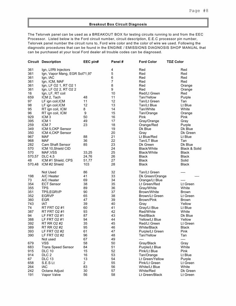
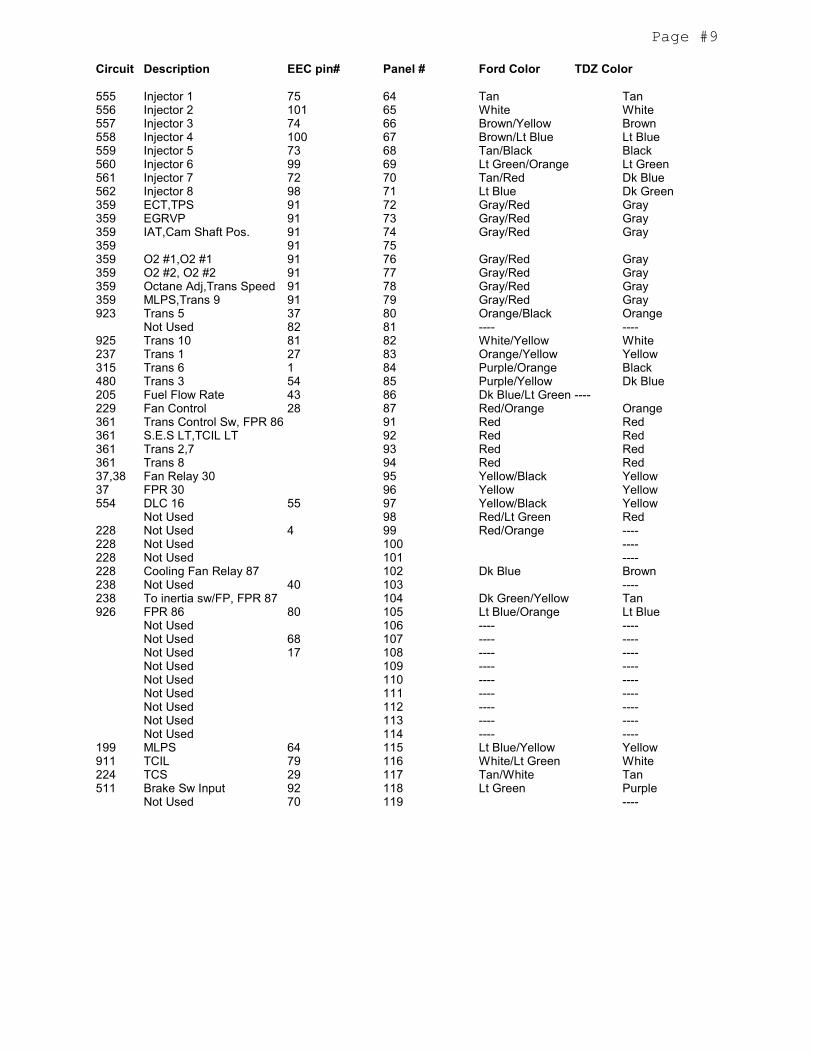
Breakout Box Circuit Diagnosis
The Telorvek panel can be used as a BREAKOUT BOX for testing circuits running to and from the EEC
Processor. Listed below is the Ford circuit number, circuit description, E.E.C processor pin number,
Telorvek panel number the circuit runs to, Ford wire color and the color of wire we used. Following the
diagnostic procedures that can be found in the ENGINE / EMISSIONS DIAGNOSIS SHOP MANUAL that
can be purchased at your local Ford dealer all trouble codes can be diagnosed.
Circuit Description EEC pin# Panel # Ford Color TDZ Color
361 Ign, Lf/Rt Injectors 4 Red Red361 Ign, Vapor Mang, EGR Sol71,97 5 Red Red361 Ign, IAC 6 Red Red361 Ign, ICM, MAF 7 Red Red361 Ign, LF O2 1, RT O2 1 8 Red Orange361 Ign, LF O2 2, RT O2 2 9 Red Orange16 Ign, LF, RT coil 10 Red/Lt Green Red659 ICM 2, Tach 48 11 Tan/Yellow Purple97 LF ign coil,ICM 11 12 Tan/Lt Green Tan98 LF ign coil,ICM 12 13 Tan/Lt Blue Lt Blue95 RT ign coil, ICM 8 14 Tan/White White96 RT ign coil, ICM 9 15 Tan/Orange Orange929 ICM 3 50 16 Pink Pink395 ICM 1 49 17 Gray/Orange Gray259 ICM 7 23 18 Orange/Red Purple349 ICM 5,CKP Sensor 19 Dk Blue Dk Blue350 ICM 4,CKP Sensor 20 Gray Dk Green967 MAF 88 21 Lt Blue/Red Lt Blue968 MAF 36 22 Tan/LT Blue Tan282 Cam Shaft Sensor 85 23 Dk Green Dk Blue570 ICM 10,Shield CID 24 Black/White Black & Solid570 MAF,VSS 33,25 25 Black/White Black570,57 DLC 4,5 24,76 26 Black Black48 ICM #1 Shield, CPS 51,77 27 Black Solid570,48 ICM #2 Shield 103 28 Black Black
Not Used 86 32 Tan/Lt Green ----198 A/C Heater 41 33 Dk Green/Orange ----73 A/C Heater 69 34 Orange/Lt Blue ----354 ECT Sensor 38 35 Lt Green/Red Lt Green355 TPS 89 36 Gray/White White351 TPS,EGRVP 90 37 Brown/White Brown352 EGRVP 65 38 Brown/Lt Green Lt Green360 EGR 47 39 Brown/Pink Brown743 IAT 39 40 Gray Yellow74 RT FRT O2 #1 60 41 Gray/Lt Blue Lt Blue387 RT FRT O2 #1 93 42 Red/White White94 LF FRT O2 #1 87 43 Red/Black Dk Blue388 LF FRT O2 #1 94 44 Yellow/Lt Blue Yellow392 RT RR O2 #2 35 45 Red/Lt Green Lt Green389 RT RR O2 #2 95 46 White/Black Black393 LF FRT O2 #2 61 47 Purple/Lt Green Pink390 LF FRT O2 #2 96 48 Tan/Yellow Tan
Not used 67 49 ---- ----679 VSS 58 50 Gray/Black Gray683 Trans Speed Sensor 84 51 Purple/Lt Blue White915 DLC 10 15 52 Pink/Lt Blue Pink914 DLC 2 16 53 Tan/Orange Lt Blue67 DLC 13 13 54 Lt Green/Yellow Purple658 S.E.S Lt 2 55 Pink/Lt Green Lt Green264 IAC 83 56 White/Lt Blue White242 Octane Adjust 30 57 White/Red Dk Green191 Vapor Valve 56 58 Lt Green/Black Lt Green
Page #9
Circuit Description EEC pin# Panel # Ford Color TDZ Color
555 Injector 1 75 64 Tan Tan556 Injector 2 101 65 White White557 Injector 3 74 66 Brown/Yellow Brown558 Injector 4 100 67 Brown/Lt Blue Lt Blue559 Injector 5 73 68 Tan/Black Black560 Injector 6 99 69 Lt Green/Orange Lt Green561 Injector 7 72 70 Tan/Red Dk Blue562 Injector 8 98 71 Lt Blue Dk Green359 ECT,TPS 91 72 Gray/Red Gray359 EGRVP 91 73 Gray/Red Gray359 IAT,Cam Shaft Pos. 91 74 Gray/Red Gray359 91 75359 O2 #1,O2 #1 91 76 Gray/Red Gray359 O2 #2, O2 #2 91 77 Gray/Red Gray359 Octane Adj,Trans Speed 91 78 Gray/Red Gray359 MLPS,Trans 9 91 79 Gray/Red Gray923 Trans 5 37 80 Orange/Black Orange
Not Used 82 81 ---- ----925 Trans 10 81 82 White/Yellow White237 Trans 1 27 83 Orange/Yellow Yellow315 Trans 6 1 84 Purple/Orange Black480 Trans 3 54 85 Purple/Yellow Dk Blue205 Fuel Flow Rate 43 86 Dk Blue/Lt Green ----229 Fan Control 28 87 Red/Orange Orange361 Trans Control Sw, FPR 86 91 Red Red361 S.E.S LT,TCIL LT 92 Red Red361 Trans 2,7 93 Red Red361 Trans 8 94 Red Red37,38 Fan Relay 30 95 Yellow/Black Yellow37 FPR 30 96 Yellow Yellow554 DLC 16 55 97 Yellow/Black Yellow
Not Used 98 Red/Lt Green Red228 Not Used 4 99 Red/Orange ----228 Not Used 100 ----228 Not Used 101 ----228 Cooling Fan Relay 87 102 Dk Blue Brown238 Not Used 40 103 ----238 To inertia sw/FP, FPR 87 104 Dk Green/Yellow Tan926 FPR 86 80 105 Lt Blue/Orange Lt Blue
Not Used 106 ---- ----Not Used 68 107 ---- ----Not Used 17 108 ---- ----Not Used 109 ---- ----Not Used 110 ---- ----Not Used 111 ---- ----Not Used 112 ---- ----Not Used 113 ---- ----Not Used 114 ---- ----
199 MLPS 64 115 Lt Blue/Yellow Yellow911 TCIL 79 116 White/Lt Green White224 TCS 29 117 Tan/White Tan511 Brake Sw Input 92 118 Lt Green Purple
Not Used 70 119 ----
Page #10
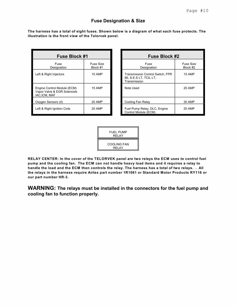
Fuse Designation & Size
The harness has a total of eight fuses. Shown below is a diagram of what each fuse protects. The
illustration is the front view of the Telorvek panel.
Fuse Block #1 Fuse Block #2
FuseDesignation
Fuse SizeBlock #1
FuseDesignation
Fuse SizeBlock #2
Left & Right Injectors 15 AMP Transmission Control Switch, FPR86, S.E.S LT, TCIL LT,Transmission
15 AMP
Engine Control Module (ECM)Vapor Valve & EGR SolenoidsIAC,ICM, MAF
15 AMP Note Used 20 AMP
Oxygen Sensors (4) 20 AMP Cooling Fan Relay 30 AMP
Left & Right Ignition Coils 20 AMP Fuel Pump Relay, DLC, EngineControl Module (ECM)
20 AMP
FUEL PUMPRELAY
COOLING FANRELAY
RELAY CENTER: In the cover of the TELORVEK panel are two relays the ECM uses to control fuel
pump and the cooling fan. The ECM can not handle heavy load items and it requires a relay to
handle the load and the ECM then controls the relay. The harness has a total of two relays. . All
the relays in the harness require Airtex part number 1R1061 or Standard Motor Products RY116 or
our part number HR-3.
WARNING: The relays must be installed in the connectors for the fuel pump andcooling fan to function properly.
Page #11
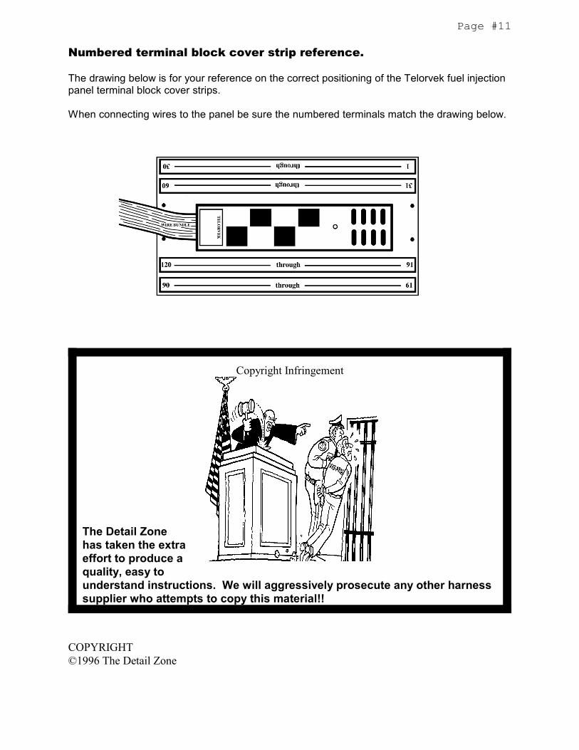
Numbered terminal block cover strip reference.
The drawing below is for your reference on the correct positioning of the Telorvek fuel injectionpanel terminal block cover strips.
When connecting wires to the panel be sure the numbered terminals match the drawing below.
Copyright Infringement
The Detail Zonehas taken the extraeffort to produce aquality, easy tounderstand instructions. We will aggressively prosecute any other harnesssupplier who attempts to copy this material!!
COPYRIGHT©1996 The Detail Zone