efi swapper's guide
TRANSCRIPT
This guide is designed specifically to swap a 1985-1992 GM TPI EFI system/engine into a 1970-81 Camaro. Though, for the most part, it can be used to swap in a TBI or LT1/LT4 engine/EFI system as well. All three engines install like a conventional engine on the existing motor mounts and they have the same transmission bell housing flange. The newest LS1/LS6 is a completely different animal altogether requiring extensive chassis modifications to install and will not be covered in this article.
The first thing you need to take stock of is your vehicle and the system you will be installing. You need to also consider the emissions regulations in your state and how you will meet those requirements. I’ll touch on the emissions system briefly, telling how to hook it up. The emissions control systems are not essential to engine operation (save for maybe PCV and canister purge), but again, the emissions regulations will dictate their necessity from a legal standpoint. In California, there is a rolling 30 year exemption meaning that currently 1973 and older cars are exempt from smog. As such, I am not using EGR, AIR injection, or any of the other late model smog devices. However, I did retain my 1971 charcoal canister purge and PCV system.
This article will cover two possible scenarios. The first is that you have
bought an entire engine/transmission assembly or just the engine. You may or may not have the factory wiring harness and computer, you may or may not all of the sensors, injectors, and relays, or have bought new sensors to replace old or damaged ones. In this scenario, you have already taken out your old engine and or transmission and installed the new one in its place. You now need to reconfigure the rest of the vehicle to run the new power plant. If you are installing an LT1, this is your only scenario since the intake manifold cannot be bolted on to an older small block without extensive modifications. However, if you’re bent on doing something like that, visit the www.thirdgen.org site and do a search. Several people have adapted LT1 manifolds to work the TPI. I will touch briefly on the installation of a TH700R4 and how to adapt it in to a 2nd gen since this is what I did. However, I will not discuss converting to a later model stick shift since I have no experience in that area.
The second scenario is that you are putting the TPI/TBI system onto an
older engine. In this scenario, you have already removed the old carbureted intake manifold and bolted on the new manifold. If you have TPI, only bolt on the base plate at this point. It’ll be easier to wire and plumb the system with the upper manifold and runners off (and the distributor out). Again, you now need to reconfigure the rest of the vehicle to run the system. I’m kind of glossing over the TPI base plate or TBI manifold installation part because putting on an intake manifold or installing an engine is pretty generic and can be found in any repair manual. The only caveat I have for this scenario is putting TPI or TBI on a seriously modified engine- that is, one that has a camshaft over 214° intake duration, cylinder heads with 180cc or more intake ports, full length headers and free flowing exhaust systems, etc. Stock TPI/TBI engines were extremely restricted as far as heads, cams, and exhaust systems go. Putting a bone stock EFI system onto a modified engine like this will result in poor, disappointing
performance if you do not get the EPROM recalibrated for the new combination. This will either require you to have a professional tuning shop do it, or you can learn to do it yourself.
One thing to note before you get started is that I highly recommend using the 1990-1992 system. So much so, that I’m going to focus solely on installing this type of system. For reasons that will become apparent later in the guide, 1990-92 MAP systems are much more practical for EFI swaps than earlier 1985-1989 MAF ones (see sensor section for definitions of MAP and MAF). If you have a 1989 or earlier MAF system, you can upgrade it to the 1990-92 configuration very easily. I’ll cover that later on.
Another thing is that I would HIGHLY, HIGHLY suggest is buying a good
automotive scanner! I use an AutoXray. It’s a very nice tool. It will read trouble codes, allow you to view real time operational data from the ECM (Electronic Control Module, aka, computer) as well as record it for future reference. You can also download this data into your PC and export it into Microsoft Excel for graphing and further analysis. This tool is invaluable for diagnosing malfunctions as well as for tuning, if you decide to get into that later. Actron also has a nice scanner, but it cannot record data.
The main objective in an EFI swap is properly configuring the vehicle to
work with the system. This involves two areas- fuel and electrical systems. Both need to be brought up to date. We’ll start with the fuel system.
Vehicle Fuel System Preparation TPI/LT1 engines require a constant pressure of upwards of 40 psi to run
properly as well as a return line to the tank. TBI’s operate on a much lower pressure of about 15 psi, but even they require a return line. In both cases, it means you will need an electric fuel pump. This presents you with two choices- either an in-tank pump or an external pump.
At first glance, the external pump may appear to be the easier method, but it has several draw backs. The most obvious and complained about one is noise. Since you will be mounting the pump to the chassis, the humming of the pump will be transmitted through the frame and will be audible inside the vehicle. While only a mild annoyance, it takes away from the “factory-ness” of the swap. The second drawback is the heat generation. Cooling is mainly by convection (whereas an in-tank pump is submerged in a cooling medium, the fuel). Since there’ll be a lot of rubber (thermally insulating) padding to keep the pump mechanically isolated from the frame (to reduce vibration noise transmission) the heat conduction away from the pump is significantly reduced. Therefore, overheating the pump is a possibility. The third problem is fuel starvation. Unless internal baffling is added to the tank, low fuel levels combined with hard braking/acceleration and/or hard cornering can uncover the fuel pickup allowing
the pump to suck air. Electric fuel pumps do not like to suck air since it reduces the life of the pump significantly.
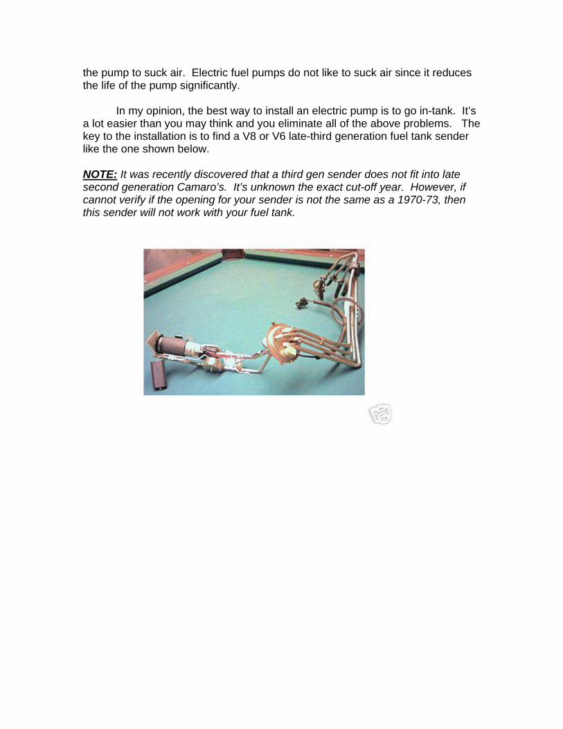
In my opinion, the best way to install an electric pump is to go in-tank. It’s
a lot easier than you may think and you eliminate all of the above problems. The key to the installation is to find a V8 or V6 late-third generation fuel tank sender like the one shown below. NOTE: It was recently discovered that a third gen sender does not fit into late second generation Camaro’s. It’s unknown the exact cut-off year. However, if cannot verify if the opening for your sender is not the same as a 1970-73, then this sender will not work with your fuel tank.
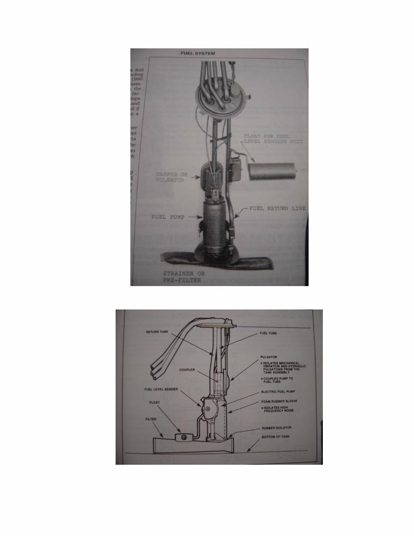
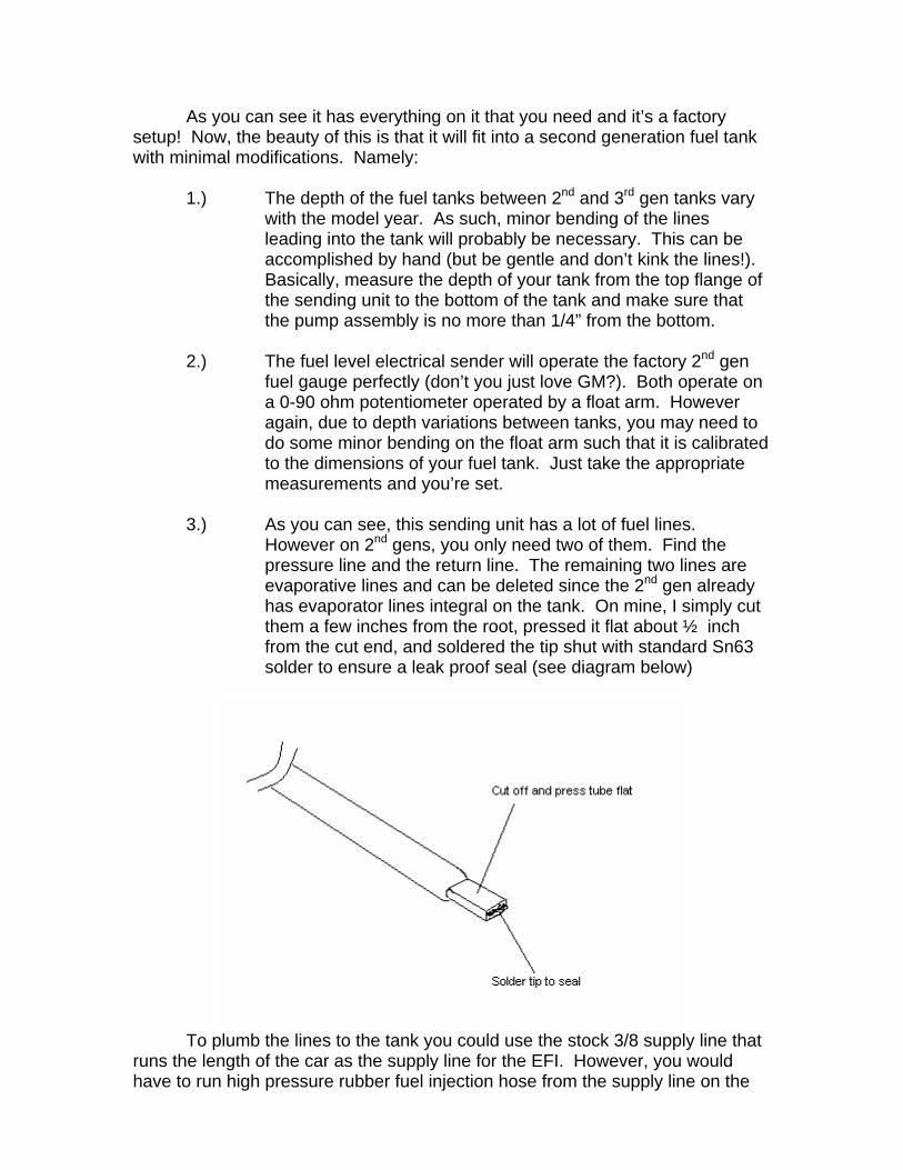
As you can see it has everything on it that you need and it’s a factory setup! Now, the beauty of this is that it will fit into a second generation fuel tank with minimal modifications. Namely:
1.) The depth of the fuel tanks between 2nd and 3rd gen tanks vary
with the model year. As such, minor bending of the lines leading into the tank will probably be necessary. This can be accomplished by hand (but be gentle and don’t kink the lines!). Basically, measure the depth of your tank from the top flange of the sending unit to the bottom of the tank and make sure that the pump assembly is no more than 1/4” from the bottom.
2.) The fuel level electrical sender will operate the factory 2nd gen
fuel gauge perfectly (don’t you just love GM?). Both operate on a 0-90 ohm potentiometer operated by a float arm. However again, due to depth variations between tanks, you may need to do some minor bending on the float arm such that it is calibrated to the dimensions of your fuel tank. Just take the appropriate measurements and you’re set.
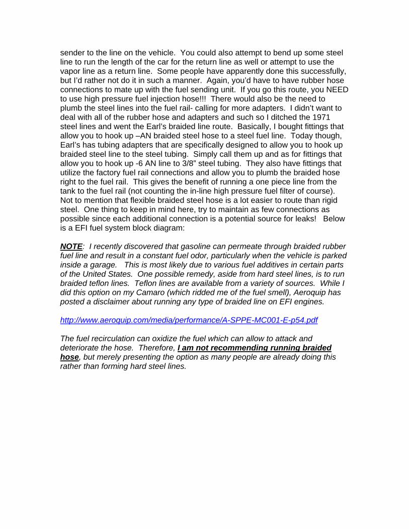
3.) As you can see, this sending unit has a lot of fuel lines.
However on 2nd gens, you only need two of them. Find the pressure line and the return line. The remaining two lines are evaporative lines and can be deleted since the 2nd gen already has evaporator lines integral on the tank. On mine, I simply cut them a few inches from the root, pressed it flat about ½ inch from the cut end, and soldered the tip shut with standard Sn63 solder to ensure a leak proof seal (see diagram below)
To plumb the lines to the tank you could use the stock 3/8 supply line that
runs the length of the car as the supply line for the EFI. However, you would have to run high pressure rubber fuel injection hose from the supply line on the
sender to the line on the vehicle. You could also attempt to bend up some steel line to run the length of the car for the return line as well or attempt to use the vapor line as a return line. Some people have apparently done this successfully, but I’d rather not do it in such a manner. Again, you’d have to have rubber hose connections to mate up with the fuel sending unit. If you go this route, you NEED to use high pressure fuel injection hose!!! There would also be the need to plumb the steel lines into the fuel rail- calling for more adapters. I didn’t want to deal with all of the rubber hose and adapters and such so I ditched the 1971 steel lines and went the Earl’s braided line route. Basically, I bought fittings that allow you to hook up –AN braided steel hose to a steel fuel line. Today though, Earl’s has tubing adapters that are specifically designed to allow you to hook up braided steel line to the steel tubing. Simply call them up and as for fittings that allow you to hook up -6 AN line to 3/8” steel tubing. They also have fittings that utilize the factory fuel rail connections and allow you to plumb the braided hose right to the fuel rail. This gives the benefit of running a one piece line from the tank to the fuel rail (not counting the in-line high pressure fuel filter of course). Not to mention that flexible braided steel hose is a lot easier to route than rigid steel. One thing to keep in mind here, try to maintain as few connections as possible since each additional connection is a potential source for leaks! Below is a EFI fuel system block diagram: NOTE: I recently discovered that gasoline can permeate through braided rubber fuel line and result in a constant fuel odor, particularly when the vehicle is parked inside a garage. This is most likely due to various fuel additives in certain parts of the United States. One possible remedy, aside from hard steel lines, is to run braided teflon lines. Teflon lines are available from a variety of sources. While I did this option on my Camaro (which ridded me of the fuel smell), Aeroquip has posted a disclaimer about running any type of braided line on EFI engines. http://www.aeroquip.com/media/performance/A-SPPE-MC001-E-p54.pdf The fuel recirculation can oxidize the fuel which can allow to attack and deteriorate the hose. Therefore, I am not recommending running braided hose, but merely presenting the option as many people are already doing this rather than forming hard steel lines.
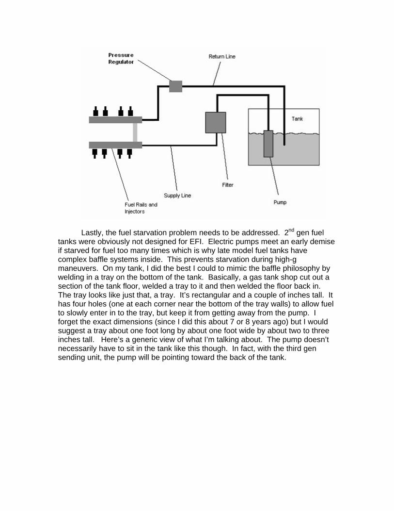
Lastly, the fuel starvation problem needs to be addressed. 2nd gen fuel
tanks were obviously not designed for EFI. Electric pumps meet an early demise if starved for fuel too many times which is why late model fuel tanks have complex baffle systems inside. This prevents starvation during high-g maneuvers. On my tank, I did the best I could to mimic the baffle philosophy by welding in a tray on the bottom of the tank. Basically, a gas tank shop cut out a section of the tank floor, welded a tray to it and then welded the floor back in. The tray looks like just that, a tray. It’s rectangular and a couple of inches tall. It has four holes (one at each corner near the bottom of the tray walls) to allow fuel to slowly enter in to the tray, but keep it from getting away from the pump. I forget the exact dimensions (since I did this about 7 or 8 years ago) but I would suggest a tray about one foot long by about one foot wide by about two to three inches tall. Here’s a generic view of what I’m talking about. The pump doesn’t necessarily have to sit in the tank like this though. In fact, with the third gen sending unit, the pump will be pointing toward the back of the tank.
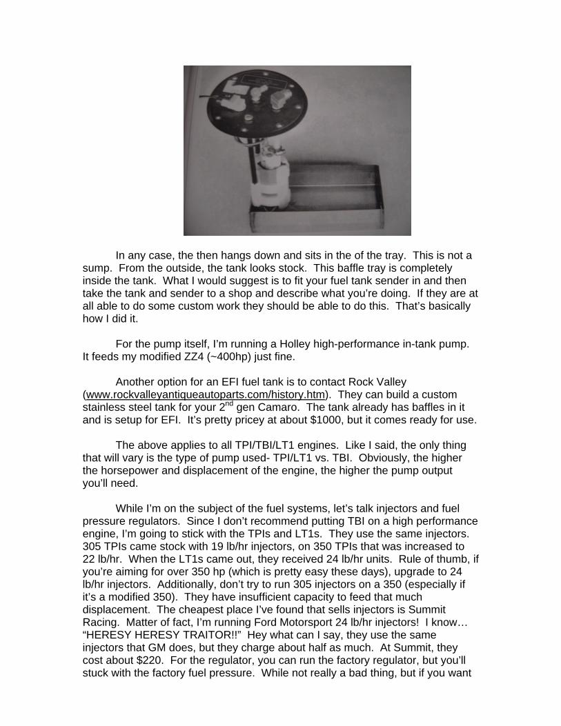
In any case, the then hangs down and sits in the of the tray. This is not a
sump. From the outside, the tank looks stock. This baffle tray is completely inside the tank. What I would suggest is to fit your fuel tank sender in and then take the tank and sender to a shop and describe what you’re doing. If they are at all able to do some custom work they should be able to do this. That’s basically how I did it.
For the pump itself, I’m running a Holley high-performance in-tank pump.
It feeds my modified ZZ4 (~400hp) just fine.
Another option for an EFI fuel tank is to contact Rock Valley (www.rockvalleyantiqueautoparts.com/history.htm). They can build a custom stainless steel tank for your 2nd gen Camaro. The tank already has baffles in it and is setup for EFI. It’s pretty pricey at about $1000, but it comes ready for use.
The above applies to all TPI/TBI/LT1 engines. Like I said, the only thing
that will vary is the type of pump used- TPI/LT1 vs. TBI. Obviously, the higher the horsepower and displacement of the engine, the higher the pump output you’ll need.
While I’m on the subject of the fuel systems, let’s talk injectors and fuel
pressure regulators. Since I don’t recommend putting TBI on a high performance engine, I’m going to stick with the TPIs and LT1s. They use the same injectors. 305 TPIs came stock with 19 lb/hr injectors, on 350 TPIs that was increased to 22 lb/hr. When the LT1s came out, they received 24 lb/hr units. Rule of thumb, if you’re aiming for over 350 hp (which is pretty easy these days), upgrade to 24 lb/hr injectors. Additionally, don’t try to run 305 injectors on a 350 (especially if it’s a modified 350). They have insufficient capacity to feed that much displacement. The cheapest place I’ve found that sells injectors is Summit Racing. Matter of fact, I’m running Ford Motorsport 24 lb/hr injectors! I know… “HERESY HERESY TRAITOR!!” Hey what can I say, they use the same injectors that GM does, but they charge about half as much. At Summit, they cost about $220. For the regulator, you can run the factory regulator, but you’ll stuck with the factory fuel pressure. While not really a bad thing, but if you want
to up the pressure a little you’ll have to install an adjustable fuel pressure regulator. There are a ton of them out there- Crane, TPI Specialties, Granatelli, Holley, etc. They’re all pretty much the same, so whatever strikes your fancy.
Injector operation varies between TPIs and LT1s. All TPIs were batch fire
systems. That is, the computer alternately fires all four driver side injectors then all four passenger side injectors. 1993 LT1s had the same style injector operation. However in 1994, GM changed to sequential injection where each injector is timed to fire per the engine firing order. Sequential injection has a little bit of an advantage at low RPMs (usually showing up in idle quality). But in the mid-range and high RPMs, the speed of the engine is high enough that the timing of the injectors becomes less important.
Lastly, remember that you need a high pressure EFI fuel filter!!
And, it’s directional at that. Make sure you install it with the arrow (on the filter housing) pointing in the right direction!!! Well, this pretty much takes care of the fuel system. Vehicle Electrical System Preparation
The electrical system of an EFI system is not as complicated as you might
think. Nonetheless, the vehicle must first be prepared to handle the demands of a late model engine management system. Like I said previously, they call the system “stand-alone” because of the system’s minimal interfacing with the rest of the vehicle’s electrical system. On the EFI harness, the only places where the system connects electrically to the vehicle are power and ground. There is one hook up to the battery, one hookup to +12V switched power source, and a few ground locations (typically engine and chassis). As such, the system basically stands alone. I will take you through the electrical preparation, but also guiding you through the engine schematic explaining the sensor operation. Again, this is something most TPI swapping guides do not do. If you are unfamiliar with wiring schematics, this will help you familiarize yourself with them. It’s important that you do so that when problems arise with the installation (and they usually do the first time through), you will be able to more successfully diagnose the situation.
First of all, you need to make sure that your vehicle’s electrical system is
up to the task of powering an EFI system! Remember, you’re going to be adding eight fuel injectors, a computer, a fuel pump, electric fans (likely), sensors, relays, etc. This is going to place a much heavier demand than your original electrical system was designed to handle. First, examine your power wire going from the battery to the alternator- make sure it is in good condition. In fact, I would strongly suggest upgrading it to a heavier gauge wire since you’re going to have to have a high output alternator. Also, ensure you have excellent (not just good) grounds going from the battery to the engine, engine to chassis, and even battery to chassis. It sounds redundant, but trust me, EFI systems do not like electrical ground loops. All of your chassis grounds from the EFI harness must
not be more than 2 ohms to the main battery ground otherwise you’ll run into quirky problems. You can check this by putting an ohmmeter from the ground point in question to the negative battery terminal. This value is what the computer will see.
Now, since I went with a 1988-1992 serpentine belt drive, I opted for the CS-130 style 105 amp alternator from a 1990 Camaro. It more than supplies all of my power needs (including my stereo amplifiers). By the way, the serpentine belt drive bracketry will in fact bolt up to an older block. It uses the same accessory bolt holes on the cylinder heads and block from 1955 up to 1992. The only exception is if you try to put Camaro brackets onto L98 Corvette heads. There is one bolt hole missing on the passenger side head that you will need to drill and tap. I found this out the hard way when I put my ZZ4 in. But getting back to the topic at hand, if you opt for a serpentine belt drive, you’ll have to convert your 2nd gen electrical system to run an alternator with an internal voltage regulator, in which case the external regulator (mounted on the driver’s side of the radiator support) is deleted. This is due mostly to the fact that CS-130 alternators are the only ones that will bolt up to the serpentine bracket. For the electrical conversion, contact MAD enterprises (www.madelectrical.com). Ask them for the kit for the CS-130 alternator (www.madelectrical.com/catalog/cs-130.shtml). You need only to supply an alternator; the kit has everything else. When you go to the parts house to get your alternator, take note of how the electrical terminals are clocked on the back of the unit. Make sure it is compatible you’re your setup. However, if you want to maintain the v-belt style drive system, simply ask for the wiring kit for a 12SI (94 amp) alternator wiring kit (www.madelectrical.com/catalog/alt-1.shtml). These alternators were used on 1984 305G engines. This kit also does away with the external regulator. Since your original alternator was likely down in the 63 amp range, you can see why having heavier power and ground wires are important.
Ignition system preparation
The next thing you need to do is prepare the vehicle for the EFI ignition
system. Pre-1975 Camaros ran a points style ignition system in which the +12V feed to the coil contained a resistor wire so as not to burn up the points. Since EFI ignition systems utilize an HEI distributor, this resistor wire must be deleted and replaced with a minimum of 12 gauge wire. What I did was to take the bulkhead connector off the firewall (driver’s side, under the brake booster) and remove the factory pink ignition wire and then install a 12 gauge wire in its place, running from the bulkhead connector straight to the distributor +12V coil feed. This ensures a good current carrying capability because an HEI will not function properly with less than a +12V input. Once this is done, the HEI is simply a drop-in replacement for the original points distributor. Post-1975 guys don’t have to worry about this since they already have HEI. BUT!! EFI distributors are completely computer controlled. That is, the computer manages the spark advance, which is why there are no vacuum canisters on these distributors. You cannot run an older vacuum style HEI with EFI. It will not work… period.
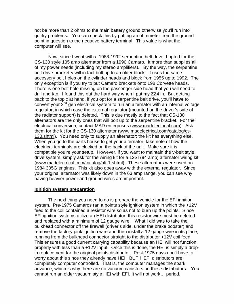
One other thing about the distributors: There are two possibilities for EFI HEI distributors. One is the Corvette so-called large-cap unit where the coil is integral in the distributor cap. It is highly similar in appearance to the older HEI’s but again, no vacuum advance. The other option is the Camaro/Truck so-called small-cap design. This unit uses an external coil. Both perform the same, but the installation is a little different. I like the large-cap because of the cleaner look.
Below is the small cap version.
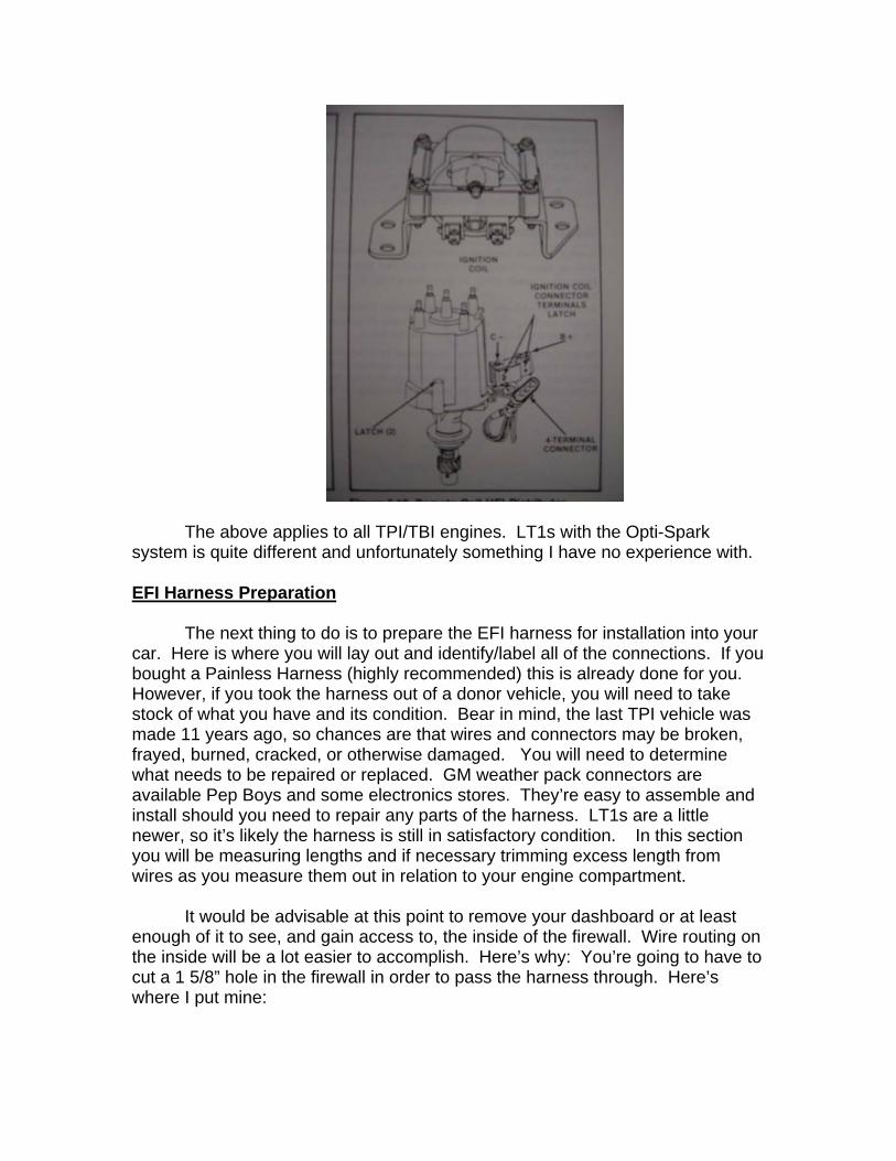
The above applies to all TPI/TBI engines. LT1s with the Opti-Spark system is quite different and unfortunately something I have no experience with.
EFI Harness Preparation
The next thing to do is to prepare the EFI harness for installation into your car. Here is where you will lay out and identify/label all of the connections. If you bought a Painless Harness (highly recommended) this is already done for you. However, if you took the harness out of a donor vehicle, you will need to take stock of what you have and its condition. Bear in mind, the last TPI vehicle was made 11 years ago, so chances are that wires and connectors may be broken, frayed, burned, cracked, or otherwise damaged. You will need to determine what needs to be repaired or replaced. GM weather pack connectors are available Pep Boys and some electronics stores. They’re easy to assemble and install should you need to repair any parts of the harness. LT1s are a little newer, so it’s likely the harness is still in satisfactory condition. In this section you will be measuring lengths and if necessary trimming excess length from wires as you measure them out in relation to your engine compartment.
It would be advisable at this point to remove your dashboard or at least
enough of it to see, and gain access to, the inside of the firewall. Wire routing on the inside will be a lot easier to accomplish. Here’s why: You’re going to have to cut a 1 5/8” hole in the firewall in order to pass the harness through. Here’s where I put mine:
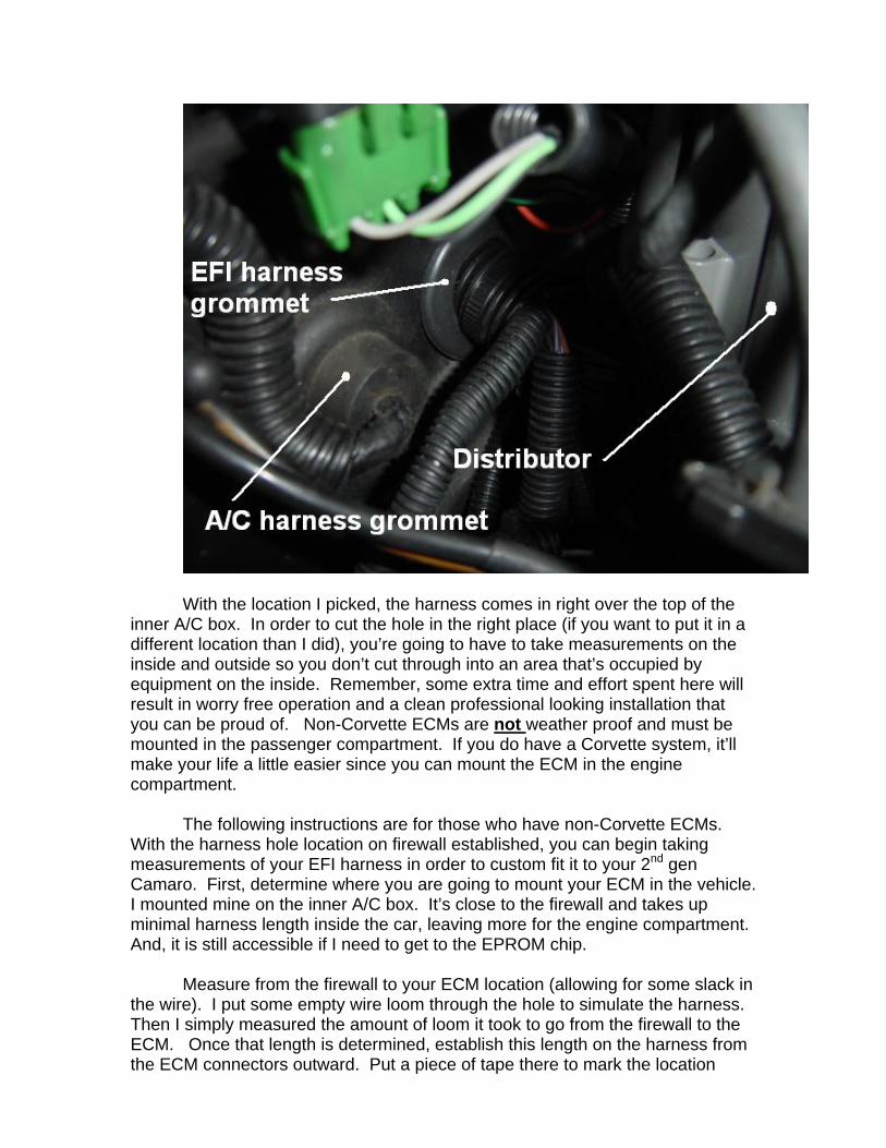
With the location I picked, the harness comes in right over the top of the
inner A/C box. In order to cut the hole in the right place (if you want to put it in a different location than I did), you’re going to have to take measurements on the inside and outside so you don’t cut through into an area that’s occupied by equipment on the inside. Remember, some extra time and effort spent here will result in worry free operation and a clean professional looking installation that you can be proud of. Non-Corvette ECMs are not weather proof and must be mounted in the passenger compartment. If you do have a Corvette system, it’ll make your life a little easier since you can mount the ECM in the engine compartment.
The following instructions are for those who have non-Corvette ECMs.
With the harness hole location on firewall established, you can begin taking measurements of your EFI harness in order to custom fit it to your 2nd gen Camaro. First, determine where you are going to mount your ECM in the vehicle. I mounted mine on the inner A/C box. It’s close to the firewall and takes up minimal harness length inside the car, leaving more for the engine compartment. And, it is still accessible if I need to get to the EPROM chip.
Measure from the firewall to your ECM location (allowing for some slack in
the wire). I put some empty wire loom through the hole to simulate the harness. Then I simply measured the amount of loom it took to go from the firewall to the ECM. Once that length is determined, establish this length on the harness from the ECM connectors outward. Put a piece of tape there to mark the location
where harness enters the engine compartment. This is your measurement reference point.
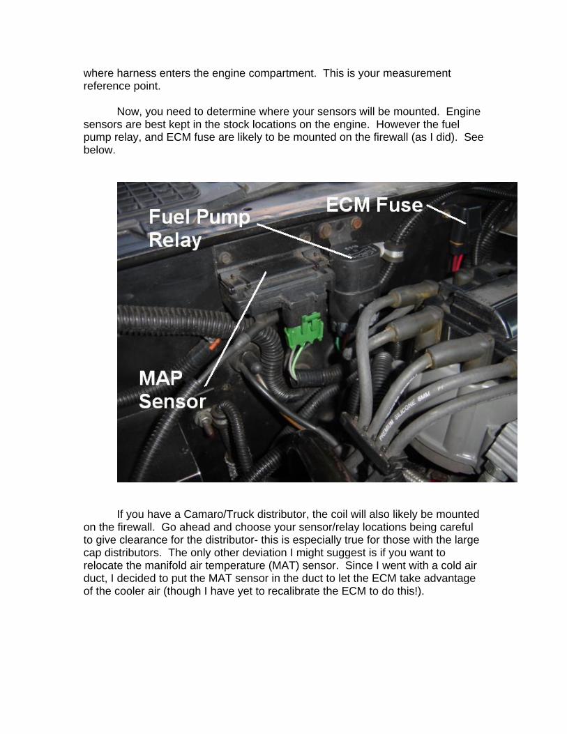
Now, you need to determine where your sensors will be mounted. Engine
sensors are best kept in the stock locations on the engine. However the fuel pump relay, and ECM fuse are likely to be mounted on the firewall (as I did). See below.
If you have a Camaro/Truck distributor, the coil will also likely be mounted
on the firewall. Go ahead and choose your sensor/relay locations being careful to give clearance for the distributor- this is especially true for those with the large cap distributors. The only other deviation I might suggest is if you want to relocate the manifold air temperature (MAT) sensor. Since I went with a cold air duct, I decided to put the MAT sensor in the duct to let the ECM take advantage of the cooler air (though I have yet to recalibrate the ECM to do this!).
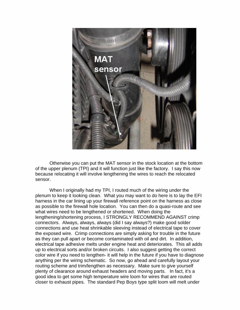
Otherwise you can put the MAT sensor in the stock location at the bottom
of the upper plenum (TPI) and it will function just like the factory. I say this now because relocating it will involve lengthening the wires to reach the relocated sensor.
When I originally had my TPI, I routed much of the wiring under the
plenum to keep it looking clean. What you may want to do here is to lay the EFI harness in the car lining up your firewall reference point on the harness as close as possible to the firewall hole location. You can then do a quasi-route and see what wires need to be lengthened or shortened. When doing the lengthening/shortening process, I STRONGLY RECOMMEND AGAINST crimp connectors. Always, always, always (did I say always?) make good solder connections and use heat shrinkable sleeving instead of electrical tape to cover the exposed wire. Crimp connections are simply asking for trouble in the future as they can pull apart or become contaminated with oil and dirt. In addition, electrical tape adhesive melts under engine heat and deteriorates. This all adds up to electrical sorts and/or broken circuits. I also suggest getting the correct color wire if you need to lengthen- it will help in the future if you have to diagnose anything per the wiring schematic. So now, go ahead and carefully layout your routing scheme and trim/lengthen as necessary. Make sure to give yourself plenty of clearance around exhaust headers and moving parts. In fact, it’s a good idea to get some high temperature wire loom for wires that are routed closer to exhaust pipes. The standard Pep Boys type split loom will melt under
high heat conditions. The high temp stuff will protect the wires from heat damage over time. Summit Racing and Jegs sell the high temperature loom.
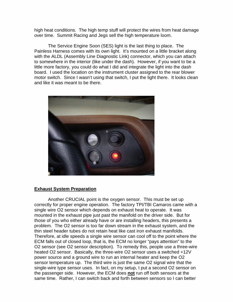
The Service Engine Soon (SES) light is the last thing to place. The
Painless Harness comes with its own light. It’s mounted on a little bracket along with the ALDL (Assembly Line Diagnostic Link) connector, which you can attach to somewhere in the interior (like under the dash). However, if you want to be a little more factory, you could do what I did and integrate the light into the dash board. I used the location on the instrument cluster assigned to the rear blower motor switch. Since I wasn’t using that switch, I put the light there. It looks clean and like it was meant to be there.
Exhaust System Preparation
Another CRUCIAL point is the oxygen sensor. This must be set up correctly for proper engine operation. The factory TPI/TBI Camaros came with a single wire O2 sensor which depends on exhaust heat to operate. It was mounted in the exhaust pipe just past the manifold on the driver side. But for those of you who either already have or are installing headers, this presents a problem. The O2 sensor is too far down stream in the exhaust system, and the thin steel header tubes do not retain heat like cast iron exhaust manifolds. Therefore, at idle speeds a single wire sensor can cool off to the point where the ECM falls out of closed loop, that is, the ECM no longer “pays attention” to the O2 sensor (see O2 sensor description). To remedy this, people use a three-wire heated O2 sensor. Basically, the three-wire O2 sensor uses a switched +12V power source and a ground wire to run an internal heater and keep the O2 sensor temperature up. The third wire is just the same O2 signal wire that the single-wire type sensor uses. In fact, on my setup, I put a second O2 sensor on the passenger side. However, the ECM does not run off both sensors at the same time. Rather, I can switch back and forth between sensors so I can better

diagnose any engine problems (if they occur on the passenger side). This dual O2 setup is not essential so you can skip it if you like. But if you want to include this feature and the description is unclear to you, you can e-mail me ([email protected]) and I’ll explain it to you further.
So, in a nutshell here are your exhaust options. I realize this section is for
electrical, but the location of your O2 sensor is important to how you will wire it in.
1.) Keep the late model exhaust manifolds if you have the entire engine. Weld an O2 sensor bung (most muffler shops have them in stock) in the exhaust pipe, as close to the manifold as possible. Keeping the late model manifolds will require you to reroute your exhaust pipes as well in order to reach the new exhaust manifold exits. In which case, option #2 might be a better way to go.
2.) Swap over to your early style manifolds and do the same as the rest of #1. The early manifolds will bolt up to the late heads and you won’t need to reroute your exhaust pipes.
3.) If you have headers, take your header off and have an O2 sensor bung welded into the inboard side of the collector. Make sure you give enough clearance to the transmission such that the O2 sensor doesn’t hit the tranny when you remount the header. This option requires the use of a three-wire O2 sensor. I use one from a 1992 Chevy Blazer and it’s little more expensive than a single-wire type. You will have to route a +12V switched power source and a ground wire to the O2 sensor along with the EFI harness signal wire. Again, lengthen the signal wire as required to reach the new O2 sensor location. Here is where I put my O2 sensors:
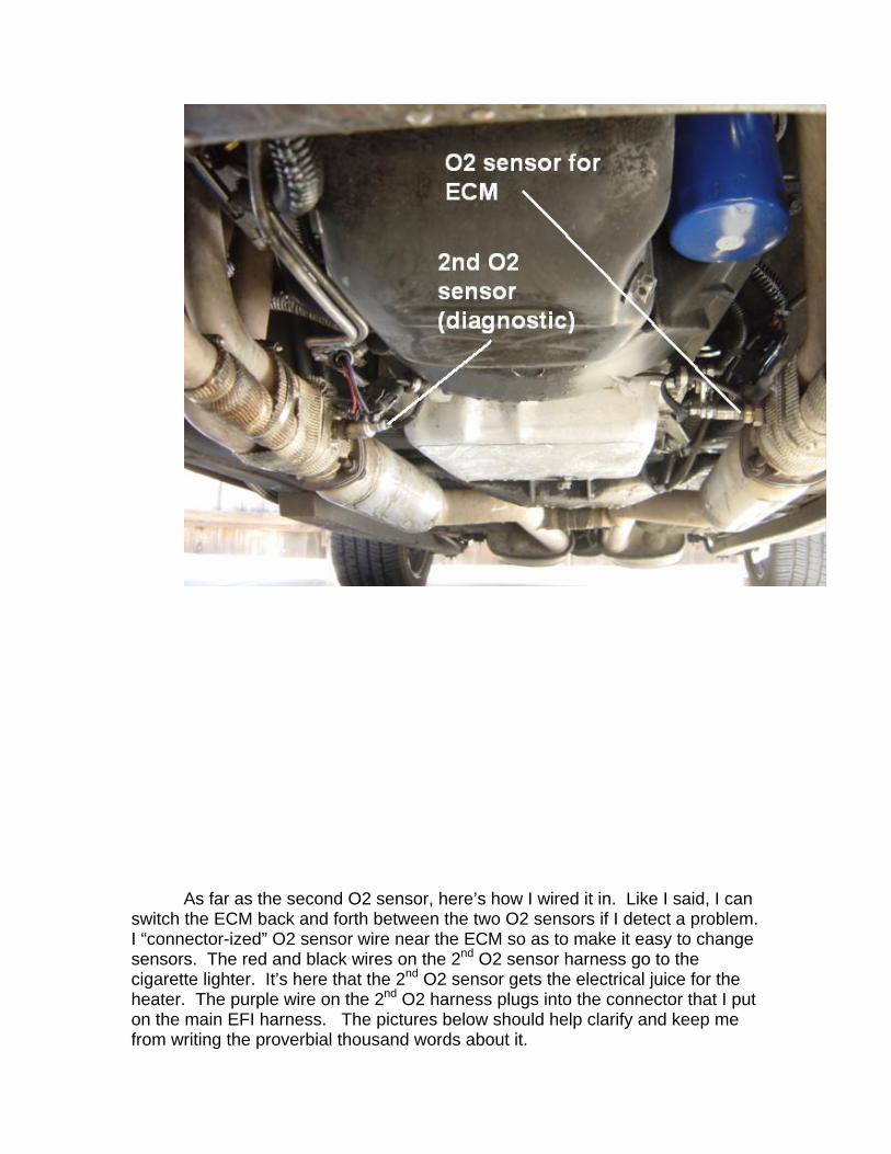
As far as the second O2 sensor, here’s how I wired it in. Like I said, I can
switch the ECM back and forth between the two O2 sensors if I detect a problem. I “connector-ized” O2 sensor wire near the ECM so as to make it easy to change sensors. The red and black wires on the 2nd O2 sensor harness go to the cigarette lighter. It’s here that the 2nd O2 sensor gets the electrical juice for the heater. The purple wire on the 2nd O2 harness plugs into the connector that I put on the main EFI harness. The pictures below should help clarify and keep me from writing the proverbial thousand words about it.
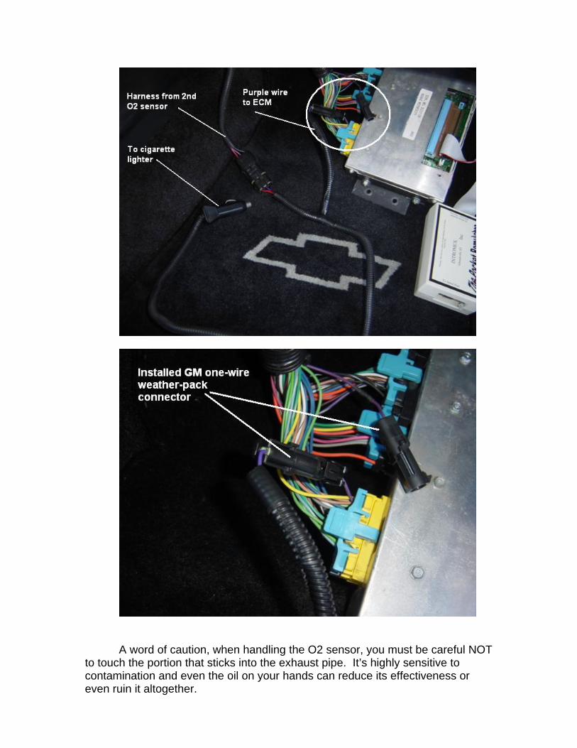
A word of caution, when handling the O2 sensor, you must be careful NOT
to touch the portion that sticks into the exhaust pipe. It’s highly sensitive to contamination and even the oil on your hands can reduce its effectiveness or even ruin it altogether.
This pretty much takes care of the exhaust system. EFI Function
I want to give you a brief run down of the various EFI components and how they function. Some knowledge of this will help you to understand how fuel injection works and aide you in diagnosing any problems that might occur.
1.) Coolant temperature sensor (CTS)
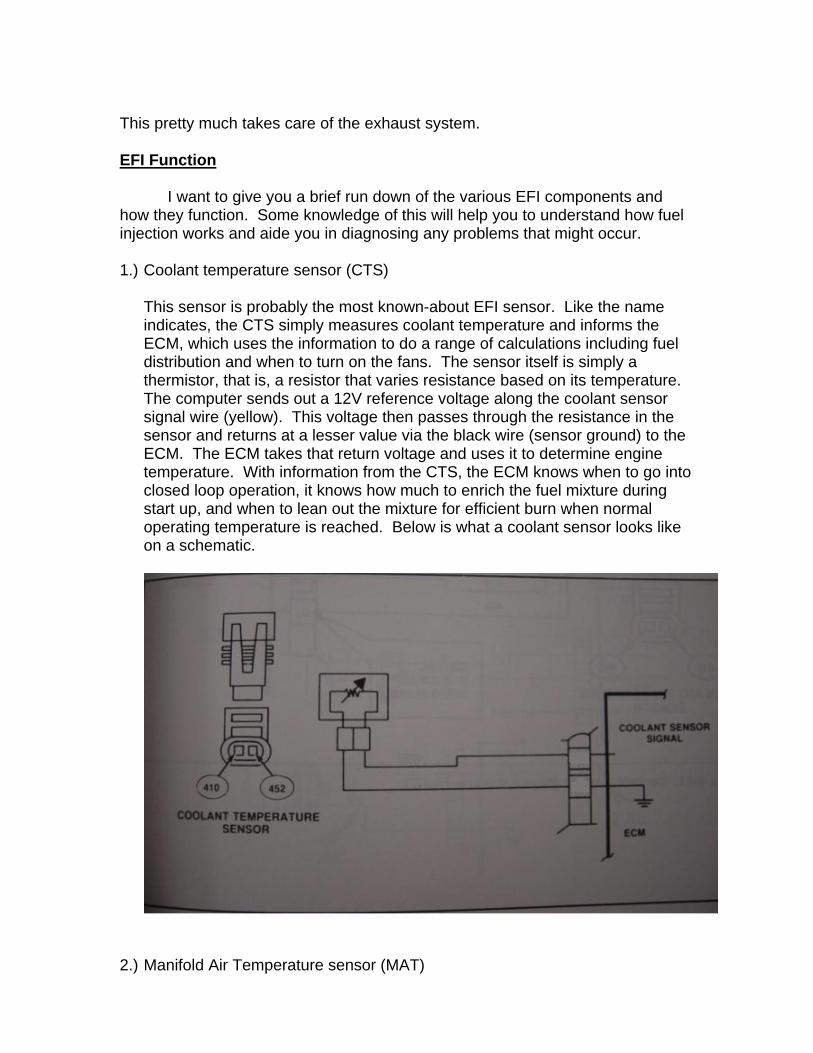
This sensor is probably the most known-about EFI sensor. Like the name indicates, the CTS simply measures coolant temperature and informs the ECM, which uses the information to do a range of calculations including fuel distribution and when to turn on the fans. The sensor itself is simply a thermistor, that is, a resistor that varies resistance based on its temperature. The computer sends out a 12V reference voltage along the coolant sensor signal wire (yellow). This voltage then passes through the resistance in the sensor and returns at a lesser value via the black wire (sensor ground) to the ECM. The ECM takes that return voltage and uses it to determine engine temperature. With information from the CTS, the ECM knows when to go into closed loop operation, it knows how much to enrich the fuel mixture during start up, and when to lean out the mixture for efficient burn when normal operating temperature is reached. Below is what a coolant sensor looks like on a schematic.
2.) Manifold Air Temperature sensor (MAT)
This sensor functions electrically identically to the CTS. Some people even use the same sensor for both. Though I prefer to use a dedicated MAT sensor for greater accuracy. With information from the MAT sensor, the ECM compensates for air density due to temperature in its airflow calculations. On a schematic, the MAT sensor will look just like the CTS.
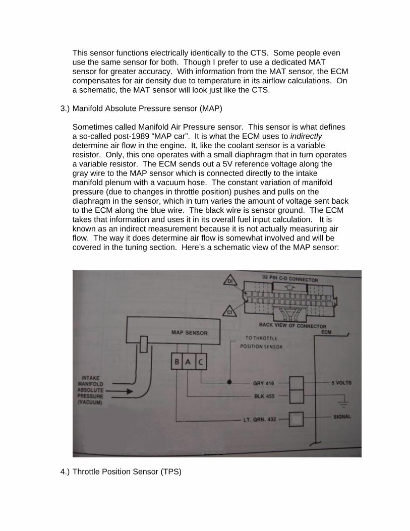
3.) Manifold Absolute Pressure sensor (MAP)
Sometimes called Manifold Air Pressure sensor. This sensor is what defines a so-called post-1989 “MAP car”. It is what the ECM uses to indirectly determine air flow in the engine. It, like the coolant sensor is a variable resistor. Only, this one operates with a small diaphragm that in turn operates a variable resistor. The ECM sends out a 5V reference voltage along the gray wire to the MAP sensor which is connected directly to the intake manifold plenum with a vacuum hose. The constant variation of manifold pressure (due to changes in throttle position) pushes and pulls on the diaphragm in the sensor, which in turn varies the amount of voltage sent back to the ECM along the blue wire. The black wire is sensor ground. The ECM takes that information and uses it in its overall fuel input calculation. It is known as an indirect measurement because it is not actually measuring air flow. The way it does determine air flow is somewhat involved and will be covered in the tuning section. Here’s a schematic view of the MAP sensor:
4.) Throttle Position Sensor (TPS)
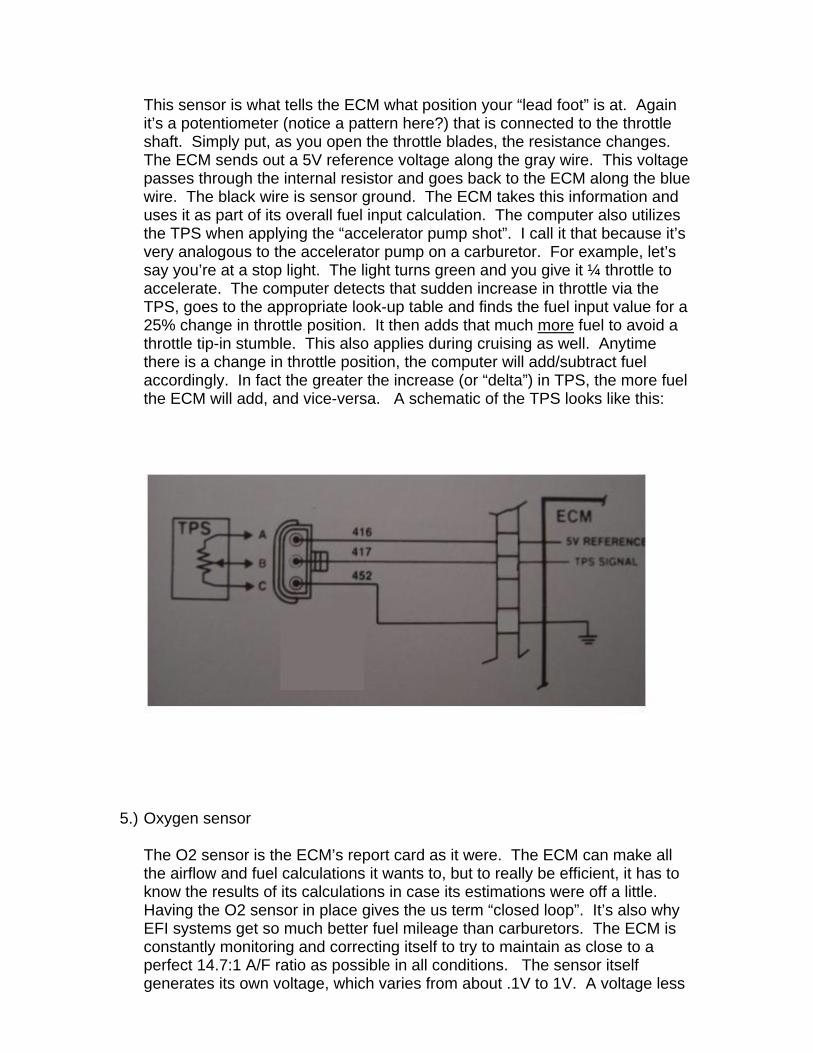
This sensor is what tells the ECM what position your “lead foot” is at. Again it’s a potentiometer (notice a pattern here?) that is connected to the throttle shaft. Simply put, as you open the throttle blades, the resistance changes. The ECM sends out a 5V reference voltage along the gray wire. This voltage passes through the internal resistor and goes back to the ECM along the blue wire. The black wire is sensor ground. The ECM takes this information and uses it as part of its overall fuel input calculation. The computer also utilizes the TPS when applying the “accelerator pump shot”. I call it that because it’s very analogous to the accelerator pump on a carburetor. For example, let’s say you’re at a stop light. The light turns green and you give it ¼ throttle to accelerate. The computer detects that sudden increase in throttle via the TPS, goes to the appropriate look-up table and finds the fuel input value for a 25% change in throttle position. It then adds that much more fuel to avoid a throttle tip-in stumble. This also applies during cruising as well. Anytime there is a change in throttle position, the computer will add/subtract fuel accordingly. In fact the greater the increase (or “delta”) in TPS, the more fuel the ECM will add, and vice-versa. A schematic of the TPS looks like this:
5.) Oxygen sensor
The O2 sensor is the ECM’s report card as it were. The ECM can make all the airflow and fuel calculations it wants to, but to really be efficient, it has to know the results of its calculations in case its estimations were off a little. Having the O2 sensor in place gives the us term “closed loop”. It’s also why EFI systems get so much better fuel mileage than carburetors. The ECM is constantly monitoring and correcting itself to try to maintain as close to a perfect 14.7:1 A/F ratio as possible in all conditions. The sensor itself generates its own voltage, which varies from about .1V to 1V. A voltage less
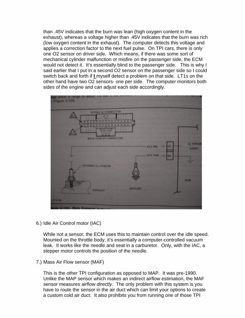
than .45V indicates that the burn was lean (high oxygen content in the exhaust), whereas a voltage higher than .45V indicates that the burn was rich (low oxygen content in the exhaust). The computer detects this voltage and applies a correction factor to the next fuel pulse. On TPI cars, there is only one O2 sensor on driver side. Which means, if there was some sort of mechanical cylinder malfunction or misfire on the passenger side, the ECM would not detect it. It’s essentially blind to the passenger side. This is why I said earlier that I put in a second O2 sensor on the passenger side so I could switch back and forth if I myself detect a problem on that side. LT1s on the other hand have two O2 sensors- one per side. The computer monitors both sides of the engine and can adjust each side accordingly.
6.) Idle Air Control motor (IAC)
While not a sensor, the ECM uses this to maintain control over the idle speed. Mounted on the throttle body, it’s essentially a computer-controlled vacuum leak. It works like the needle and seat in a carburetor. Only, with the IAC, a stepper motor controls the position of the needle.
7.) Mass Air Flow sensor (MAF)
This is the other TPI configuration as opposed to MAP. It was pre-1990. Unlike the MAP sensor which makes an indirect airflow estimation, the MAF sensor measures airflow directly. The only problem with this system is you have to route the sensor in the air duct which can limit your options to create a custom cold air duct. It also prohibits you from running one of those TPI
filters that attach directly to the throttle body (though this particular setup is extremely noisy and not recommended). To top it all off, MAF sensors are expensive to replace, unlike MAP sensors which are dirt cheap. This is why I recommend against installing a MAF system. Years ago, the MAP vs MAF argument used to be that MAF cars adapt to modifications easier, like cams, heads, etc, whereas MAP cars do not. However, those were the days when custom tuning was limited to the select few in the professional shops and when Jet and Hypertech off-the-shelf chips were actually considered high performance! Today however, with the myriad of personal custom tuning going on, that argument is no longer valid. With some careful studying combined with some enthusiasm, you can easily learn to tune an EFI system (TPI, TBI, or LT1). If you have a MAF system, don’t worry, all you need to do is give Painless Wiring a call and order their MAP harness as well as get a MAP computer. Part number for the MAP computer is 1227730. Among the EFI crowd, it’s simply known as a 7730 or 730. For 1994-1996 LT1s, you have to run the MAF sensor.
8.) Cold Start Injector
This is also a pre-1990 contraption. It is a kluge, tacked-on, 9th injector that mounts on the driver side of the TPI base plate. The pre-1990 ECM uses this injector to richen the mixture during cold start conditions. In 1990 however, this injector was deleted and GM began to use an enrichment subroutine in the ECM programming to simply use the eight primary injectors a little richer during cold start conditions. Again, if you do what I recommend and convert from MAF to MAP you’ll have to delete this cold start injector and plug the hole.
9.) Knock Sensor
This sensor does for the ignition system what the O2 sensor does for the fuel system- that is, make it closed loop. The knock sensor will tell the ECM to reduce the timing if pre-ignition detonation is detected. It’s simply a piezzo-electric crystal that will detect vibration and generate a voltage. It’s this voltage that the ECM uses as a signal that knock is present or about to take place. This sensor typically screws into the lower part of the block in one of the drain holes. Make sure you use Teflon sealer on the threads if the hole penetrates into the water jacket, otherwise you’ll have a nice little leak on your hands. A knock sensor will protect your engine if you get a load of bad gas, or are in a severe load condition like going up a steep hill in a higher gear. The knock sensor schematic is shown below.
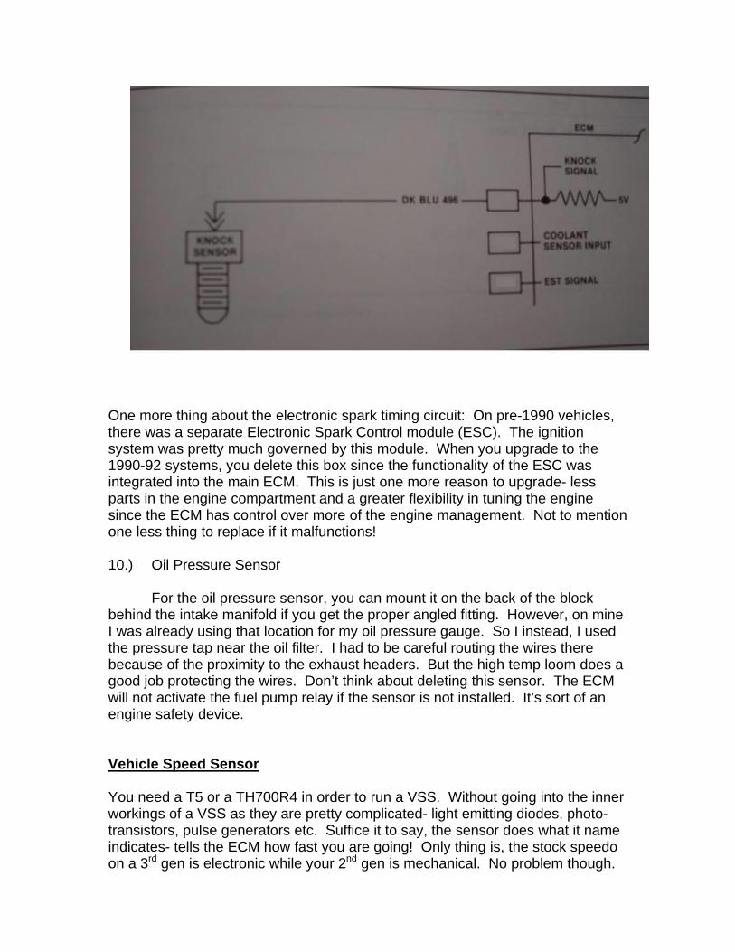
One more thing about the electronic spark timing circuit: On pre-1990 vehicles, there was a separate Electronic Spark Control module (ESC). The ignition system was pretty much governed by this module. When you upgrade to the 1990-92 systems, you delete this box since the functionality of the ESC was integrated into the main ECM. This is just one more reason to upgrade- less parts in the engine compartment and a greater flexibility in tuning the engine since the ECM has control over more of the engine management. Not to mention one less thing to replace if it malfunctions! 10.) Oil Pressure Sensor
For the oil pressure sensor, you can mount it on the back of the block behind the intake manifold if you get the proper angled fitting. However, on mine I was already using that location for my oil pressure gauge. So I instead, I used the pressure tap near the oil filter. I had to be careful routing the wires there because of the proximity to the exhaust headers. But the high temp loom does a good job protecting the wires. Don’t think about deleting this sensor. The ECM will not activate the fuel pump relay if the sensor is not installed. It’s sort of an engine safety device. Vehicle Speed Sensor You need a T5 or a TH700R4 in order to run a VSS. Without going into the inner workings of a VSS as they are pretty complicated- light emitting diodes, photo-transistors, pulse generators etc. Suffice it to say, the sensor does what it name indicates- tells the ECM how fast you are going! Only thing is, the stock speedo on a 3rd gen is electronic while your 2nd gen is mechanical. No problem though.
Stealth Conversions has just the thing. (http://www.jagsthatrun.com/Pages/SpeedSensors_Speedometer.html) You’ll need to get the four-pulse sine wave unit, used for 1990–1993 TPI V-8, 3.1 V-6, and 3.4 V-6. This sensor hooks up to a receptacle in the transmission tail housing. With this sensor from Stealth, you can just plug your stock speedometer cable right into it. Lastly, make sure your speedometer gear is the right one for the rear end ratio you are running. Otherwise, you’ll not only fool your speedometer, but it’ll throw your ECM off as well. Cooling System The cooling system for TPI/TBI engines is pretty straight forward. The inlet/outlets are the same as the older engines. For the TPIs, you can use the late model TPI upper cooling hose. It’s a bit of a tight fit on the stock 2nd gen radiator inlet, but it does fit. However, you can retain your stock 2nd gen lower radiator hose. For those of you attempting to put a serpentine belt drive on your older engine, you will need to buy a reverse rotation water pump. The serpentine belt drives the water pump in the opposite direction. Although the impeller is backwards, the water still flows in the same direction. It is not reverse flow. For cooling fans, if you intend to do a cold air tube like mine, you will need to run electric fans. Several people on the 2GCOG site have used various OEM style fan setups from LT1s, LS1s, and even Ford Taurus’. You can refer to the message board archives to find out how they mounted them. I went with Hayden twin 14” fans, fabbed up some mounting brackets. You can see what I did by going to http://f1.pg.photos.yahoo.com/ph/ultm8z/my_photos and clicking on the electric fan photos. Electrically, any way go, you can easily connect the fans to the ECM with a standard 30 amp automotive relay that you can get from Pep Boys, Autozone, Radio Shack, etc. If you have the stock TPI or LT1 fan relay setup with the wiring harness, you can use that as well. For you guys doing a custom fan setup, here is a schematic for how to hook it up with the relay. DO NOT run the fans directly off the switched ignition circuit. You’ll overload it really fast. The relay allows you to run a high current accessory without loading up the car’s own circuitry. I use one relay to power both fans.
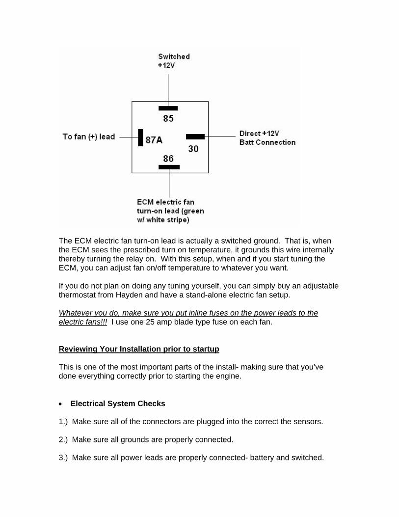
The ECM electric fan turn-on lead is actually a switched ground. That is, when the ECM sees the prescribed turn on temperature, it grounds this wire internally thereby turning the relay on. With this setup, when and if you start tuning the ECM, you can adjust fan on/off temperature to whatever you want. If you do not plan on doing any tuning yourself, you can simply buy an adjustable thermostat from Hayden and have a stand-alone electric fan setup. Whatever you do, make sure you put inline fuses on the power leads to the electric fans!!! I use one 25 amp blade type fuse on each fan. Reviewing Your Installation prior to startup This is one of the most important parts of the install- making sure that you’ve done everything correctly prior to starting the engine. • Electrical System Checks 1.) Make sure all of the connectors are plugged into the correct the sensors. 2.) Make sure all grounds are properly connected. 3.) Make sure all power leads are properly connected- battery and switched.
4.) The throttle position sensor has some adjustment to it. You’ll need to adjust it such that there is approximately .6 volts. To check it, probe the back of the connector with a voltmeter on the blue and black wires. If the voltage is too high or too low, loosen the screws and adjust the sensor until you get the correct voltage. Then retighten the screws.
• Fuel System Checks
1.) The best way to test the fuel system is simply to turn the key on (not the engine) and inspect it for leaks. You may need to turn the ignition on and off a couple of times to fully pressurize the system. The pump will prime the system but may not achieve full pressure on the first try since there is so much empty volume to fill (fuel filter, fuel lines and rails). You’ll need to hook up a fuel pressure gauge to the shrader valve on the fuel rail to read the pressure. This valve is on the passenger side behind the rear most intake runner tube. Once the system is pressurized, examine the all of the fuel connections for leaks. At about 40 psi, leaks should be readily apparent. Also, the pressure should hold steady for a long time. If you see the pressure dropping, there is a leak some place.
• Ignition timing
Since I’m completely unfamiliar with the LT1’s Opti-Spark system, I’m going to concentrate on the TPI/TBIs. For the most part, TPI and TBI systems leave the timing control to the ECM. The only thing that you can manually do is to set the base timing. Before you drop in your distributor, make sure your engine is at #1 TDC (make certain you’re not at #6 TDC!). Then drop in your distributor with the rotor pointing in the position you want the number one spark plug to be in. Put your cap on, noting where the rotor was pointing and put your wires on. SBC firing order is 1-8-4-3-6-5-7-2 in a clockwise direction around the cap. At this point you have 0° BTDC spark timing. At this point, disconnect the distributor timing bypass connector. It’s the beige wire with tan stripe and has a single inline connector. With this disconnected, the ECM has no control over the timing. Starting the car like this will cause the ECM to illuminate the SES light and throw a code 42 for an electronic spark timing error. But after you get the timing set, you’ll reconnect the bypass connector and you can simply unplug the ECM and let the codes erase.
With all of these steps complete and any problems rectified, go ahead and start the engine. Leaving the bypass connector unconnected, check your timing and set it to 6° BTDC. This is the factory timing setting. Leave it at this value for now so as to get the system running properly. Tighten down the distributor and then recheck the timing to ensure that you did not alter the advance while tightening the hold down clamp. Now shut the engine off, plug the connector back together
and restart the engine. The SES light should not be on anymore (even though the code 42 is still stored in memory). Initial system performance checks with the engine running
This is where it is really helpful (almost necessary) to have a scanner. For those of you without a scanner, all you’re really going to be able to do is to check your fuel pressure and check for any trouble codes.
In the same way you checked the fuel pressure before, check it while the
engine is running. It should be about 35 psi at idle with the vacuum on and about 39-40 with the vacuum off. If you’re using the stock regulator, this should be so by default. If it is not correct, you’ll need to go back and inspect your fuel system installation.
If you do have a scanner, plug it into the ALDL connector and, following
the instructions that came with it, configure it to your system. The things you should pay attention to on the scanner include the following:
• Verify that the system goes into closed loop and stays there. This will
usually take several minutes to occur. The coolant temperature has to reach a certain value first.
• Look at the sensor readouts- CTS, MAT, MAP, TPS, etc. The scanner will display the values for these. They should be reasonable values.
• Check the Block Learn values (BLM). They should be at 128 ± 3 for a stock engine. If your engine is modified it’s going to be significantly higher or lower. I’ll explain what BLMs are in the tuning section.
If the above check out and the engine is running smoothly, chances are the installation was a success. If your engine is stock, you’re probably done. If you put TPI on a significantly modified engine, you’re likely going to have to start looking into some tuning to get it optimized for your combination. Trouble Shooting Tips Probably the most typical problem for a first time TPI swapper is that the car won’t start. Yikes! This could be due to a whole host of possibilities.
Dealing with emissions
Depending on what your emissions laws are like in your state, you may or may not need to deal with this. From what I know of emissions laws, if you put a 1990 engine into a 1971 Camaro, you will need to get it smogged as a 1990 Camaro through a referee station. Which means you need to have all of the emissions equipment that came on the 1990. So, the only legal way to do this swap is to put the entire engine with all of the emissions equipment into your vehicle as-is. If you have the original engine harness and engine and smog equipment , then just plug the connectors into the appropriate equipment- EGR, charcoal canister purge, AIR injection, etc. If you are using a Painless Harness, you will need to buy the Painless emissions harness add-on. The standard harness does not come with this. Putting EFI on an older engine will not pass as far as I know. In any case, it would be a good idea to talk to an official at a referee station to find out what is required of you to pass BEFORE doing the swap. That way you don’t get caught with your pants down, so to speak, when you take it in to get it smogged. Performance parts and parts interchangeability
In the 1990's GM did a lot of revisions here and there to the outline and mounting (O&M)ir various cylinder heads and manifolds. Which is why the topic of interchangeability produces a 400 ft tall question mark in a lot of people's heads. There I hope this will be the "final answer" on parts interchangeability among EFI manifolds and the various cylinder head designs. If anyone finds an error here, speak up, otherwise it's going into the EFI handbook as is!!
On TPI manifolds, basically it works like this: A 1985 to 1986 TPI baseplate will bolt up to any small block Chevy iron head dating from 1955-1986 (port sizes are another story (port matching may be required), I'm just talking about physically bolting up). It will also fit the L98 (ZZZ-ZZ4) series aluminum Corvette head of any year 1986-1991 (not LT1s). This is because of the infamous center bolt hole revision that occured in 1987.
In 1987, the Camaros received a revised bolt angle on the four center bolt holes on their iron heads. To make the 1987-1992 Camaro manifolds fit the older style heads, you have to elongate the center bolt holes. The Corvette TPI manifold (1985-1991) will fit on any older style head since the Corvette's aluminum L98 heads were immune to that bolt hole revision Aftermarket companies recognized this problem from a marketing standpoint and created baseplates that bolt up to any year cylinder head 1955-1992 (non-LT1). Nearly all aftermarket aluminum heads from Edelbrock, Holley, AFR, etc, use the older style manifold bolt pattern. (unless you order one specifically for the 1987-later Camaro). This is because the 1987-later Camaro heads were such a one-off ugly duckling (as far as hot rodders were concerened) the aftermarket never latched on to that bolt hole revision. That takes care of that. BTW, trucks received the same treatment as the Camaros, for you TBI swap guys.

For high performance modifications to the TPI, there is a plethora of options. If you want to keep the original long runner design, you can go with companies like Accel, Edelbrock, TPIS, Arizona Speed and Marine, to name a few. They sell larger intake runner tubes, either a ported out baseplate or a completely new casting with bigger ports, larger throttle bodies 52mm and 58 mm (stock is 48mm), and a ported plenum (I'm not aware of any aftermarket plenums). These all increase power noticeably, but still suffer from the long runner choke off at around 5000 rpm. If you want to do away with that problem, again you have some choices. The TPIS MiniRam (which I am running) is highly similar to the LT1. In fact, many people think I have an LT1 when they first see my engine. Both the MiniRam and LT1/LT4 have nearly the same runner length (though the runner volume may vary slightly between the different manifolds). Alternatively, there is the Accel Superram and the Holley Stealth Ram. Both have a little bit longer runners. The Super Ram runner is bascially a TPI runner cut in half. And the Holley Stealth Ram is essentially a TPI plenum mounted on a carbureted tunnel ram base. I have no experience with either, but I've heard people say they like them.
Runner length impacts your torque curve in that (as a rule of thumb) the longer the runner, the "peakier" the curve. For instance on the TPIs, the 21" long runners (from plenum entry to cylinder head entry) produces a sharp peak at about 3600-3800 rpm. But after that, torque drops off dramatically and essentially disappears at about 4800-5000 rpm. To the other extreme is the LT1/LT4/MiniRam manifold. These will produce less torque than a TPI at 3600-3800 but more everywhere else. So it's up to you to fit the torque curve to the weight and setup of your vehicle. Of course the other manifolds with intermediate runner lengths will be in between these extremes.
The MiniRam will only bolt up to the older style heads (out of the box) while the TPI baseplates will bolt up to both (Superram uses a TPI baseplate). As far as the Holley Stealth Ram, I believe that will also only bolt up to early heads, but I'm not certain.
Well, after the TPIs went the way of the dodo, the LT1s were born and ran from 1992 (Camaros didn't get them until 1993) until 1996. This was sort of an intermediate design toward the inevitable LS1. However, the LT1 has some similarities and some differences from the TPIs. The most obvious is the reverse cooling. This means that the cylinder head water jacketing is different enough to prevent it from being a direct bolt on to the older block. Additonally, the manifold O&M changed- namely the bolt hole angles, the ports, and the lack of a distributor mounting hole (due to the new Opti-Spark system), and the water cross over (since the water outlet was on the pump). People have successfully put LT1 manifolds onto TPI engines, but not without extensive modifications.
As far as modifications to the LT1, some guys step to the LT4 specs. The LT4's (which appeared in 1996, right before the LS1s) put out about 30 more hp due to revised cylinder heads, cam, and intake. The way I understand it, LT1 and LT4
intakes are not even easily interchangeable among eachother due to port differences in the LT4 and LT1 heads. For aftermarket manifolds, I believe that Accel has a Superram available for LT1/LT4 guys who want a little more runner length.
Now, Vortec heads which popped up in 1996 on Trucks are another totally different animal. The bolt holes were again revised over the LT1/LT4s. Now, there were eight holes only on the ends of the heads, and they were compltely vertical. There were no fuel injection manifolds available for this head (aside from the one GM put on it in the trucks). However, since they became the new darling of the hot rodding world (due to how inexpensive they were compared to the amount of performance they offered), one company jumped on the idea of putting TPI onto these heads. Scoggins Dickey Chevrolet out of Lubbock, Texas, contracted Edelbrock to design and build a private label baseplate that would bolt up to the Vortec heads and be compatible with all existing TPI hardware. The end user would buy the heads and the baseplate and use everything else he already had. It was successful and the combination made significantly more power than a standard TPI on standard heads. Another option for the Vortec guys is this new Ram Jet manifold. In fact the Ram Jet 350 uses Vortec cylinder heads. The Ram Jet manifold requires it's own fuel rails and throttle body and it will produce similar power numbers to similar to the LT1/LT4/MiniRam manifolds- again due to the runner geometry.
An introduction to custom tuning Once you have your engine up and running, the really fun part can begin (aside from actually driving and enjoying it, that is!). As I said earlier, years ago, EFI tuning was limited to a handful of professionals who understood how it worked. Companies like Hypertech, Jet, ADS Superchips, made a lot of money selling off-the-shelf $180 “super” chips which consisted of about $5 worth of parts and depended heavily on the ignorance of the user to believe he was getting what they told him he was getting. The placebo effect was never more apparent than this. Having looked at the programming of some of these chips, I can tell you honestly that they are a complete waste of money. They only did slight modifications of the WOT settings and nothing else. This was to allow the chips to be smog legal. So called “off highway” or Stage II chips, altered the fan turn-on temperatures to work with a lower temperature thermostat. These chips were for guys who put on a K&N air filter, underdrive pulleys, hi-po spark plug wires, etc, and thought they were too heavily modified for the stock chip. Then there were the guys who really modified their engines with cams, heads, bigger manifolds, etc. If the modifications weren’t too radical, a MAF system could adapt and run satisfactorily. However, guys with MAP cars were hosed (I’ll explain the differences a little later). This was where the real custom tuning guys stepped in. You were able do this one of two ways: One was to do it mail order. With a spec sheet of your engine/transmission/rear axle combination, they would burn you a chip. This sometimes worked and sometimes not (as was more often the case). The other way was to drive into a
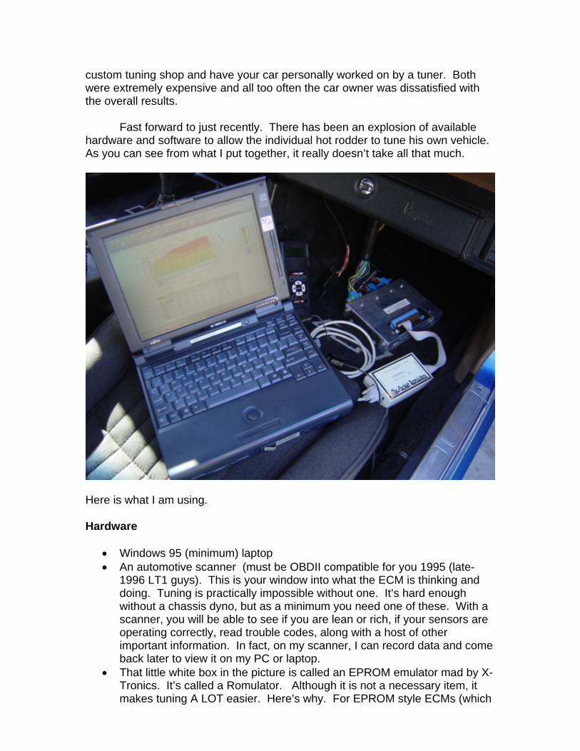
custom tuning shop and have your car personally worked on by a tuner. Both were extremely expensive and all too often the car owner was dissatisfied with the overall results. Fast forward to just recently. There has been an explosion of available hardware and software to allow the individual hot rodder to tune his own vehicle. As you can see from what I put together, it really doesn’t take all that much.
Here is what I am using. Hardware
• Windows 95 (minimum) laptop • An automotive scanner (must be OBDII compatible for you 1995 (late-
1996 LT1 guys). This is your window into what the ECM is thinking and doing. Tuning is practically impossible without one. It’s hard enough without a chassis dyno, but as a minimum you need one of these. With a scanner, you will be able to see if you are lean or rich, if your sensors are operating correctly, read trouble codes, along with a host of other important information. In fact, on my scanner, I can record data and come back later to view it on my PC or laptop.
• That little white box in the picture is called an EPROM emulator mad by X-Tronics. It’s called a Romulator. Although it is not a necessary item, it makes tuning A LOT easier. Here’s why. For EPROM style ECMs (which
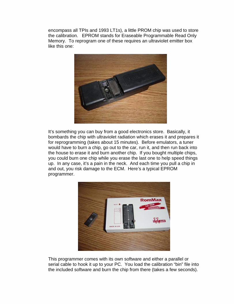
encompass all TPIs and 1993 LT1s), a little PROM chip was used to store the calibration. EPROM stands for Eraseable Programmable Read Only Memory. To reprogram one of these requires an ultraviolet emitter box like this one:
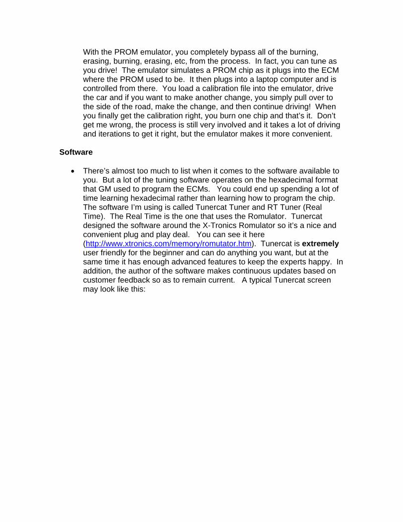
It’s something you can buy from a good electronics store. Basically, it bombards the chip with ultraviolet radiation which erases it and prepares it for reprogramming (takes about 15 minutes). Before emulators, a tuner would have to burn a chip, go out to the car, run it, and then run back into the house to erase it and burn another chip. If you bought multiple chips, you could burn one chip while you erase the last one to help speed things up. In any case, it’s a pain in the neck. And each time you pull a chip in and out, you risk damage to the ECM. Here’s a typical EPROM programmer.
This programmer comes with its own software and either a parallel or serial cable to hook it up to your PC. You load the calibration “bin” file into the included software and burn the chip from there (takes a few seconds).
With the PROM emulator, you completely bypass all of the burning, erasing, burning, erasing, etc, from the process. In fact, you can tune as you drive! The emulator simulates a PROM chip as it plugs into the ECM where the PROM used to be. It then plugs into a laptop computer and is controlled from there. You load a calibration file into the emulator, drive the car and if you want to make another change, you simply pull over to the side of the road, make the change, and then continue driving! When you finally get the calibration right, you burn one chip and that’s it. Don’t get me wrong, the process is still very involved and it takes a lot of driving and iterations to get it right, but the emulator makes it more convenient.
Software
• There’s almost too much to list when it comes to the software available to you. But a lot of the tuning software operates on the hexadecimal format that GM used to program the ECMs. You could end up spending a lot of time learning hexadecimal rather than learning how to program the chip. The software I’m using is called Tunercat Tuner and RT Tuner (Real Time). The Real Time is the one that uses the Romulator. Tunercat designed the software around the X-Tronics Romulator so it’s a nice and convenient plug and play deal. You can see it here (http://www.xtronics.com/memory/romutator.htm). Tunercat is extremely user friendly for the beginner and can do anything you want, but at the same time it has enough advanced features to keep the experts happy. In addition, the author of the software makes continuous updates based on customer feedback so as to remain current. A typical Tunercat screen may look like this:
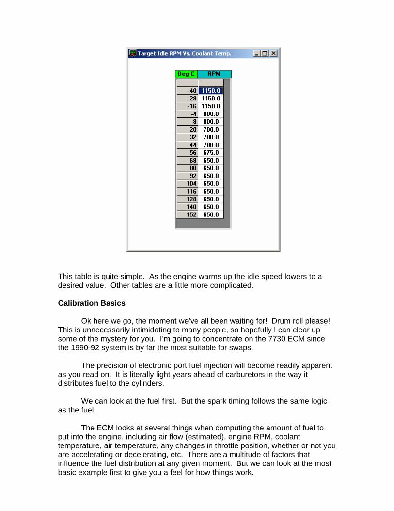
This table is quite simple. As the engine warms up the idle speed lowers to a desired value. Other tables are a little more complicated.
Calibration Basics
Ok here we go, the moment we’ve all been waiting for! Drum roll please! This is unnecessarily intimidating to many people, so hopefully I can clear up some of the mystery for you. I’m going to concentrate on the 7730 ECM since the 1990-92 system is by far the most suitable for swaps.
The precision of electronic port fuel injection will become readily apparent as you read on. It is literally light years ahead of carburetors in the way it distributes fuel to the cylinders.
We can look at the fuel first. But the spark timing follows the same logic
as the fuel. The ECM looks at several things when computing the amount of fuel to
put into the engine, including air flow (estimated), engine RPM, coolant temperature, air temperature, any changes in throttle position, whether or not you are accelerating or decelerating, etc. There are a multitude of factors that influence the fuel distribution at any given moment. But we can look at the most basic example first to give you a feel for how things work.
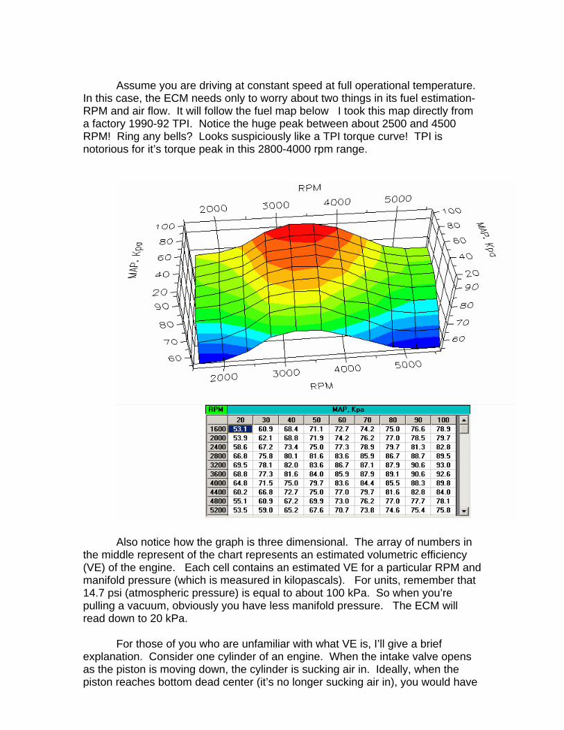
Assume you are driving at constant speed at full operational temperature.
In this case, the ECM needs only to worry about two things in its fuel estimation- RPM and air flow. It will follow the fuel map below I took this map directly from a factory 1990-92 TPI. Notice the huge peak between about 2500 and 4500 RPM! Ring any bells? Looks suspiciously like a TPI torque curve! TPI is notorious for it’s torque peak in this 2800-4000 rpm range.
Also notice how the graph is three dimensional. The array of numbers in the middle represent of the chart represents an estimated volumetric efficiency (VE) of the engine. Each cell contains an estimated VE for a particular RPM and manifold pressure (which is measured in kilopascals). For units, remember that 14.7 psi (atmospheric pressure) is equal to about 100 kPa. So when you’re pulling a vacuum, obviously you have less manifold pressure. The ECM will read down to 20 kPa.
For those of you who are unfamiliar with what VE is, I’ll give a brief explanation. Consider one cylinder of an engine. When the intake valve opens as the piston is moving down, the cylinder is sucking air in. Ideally, when the piston reaches bottom dead center (it’s no longer sucking air in), you would have
atmospheric pressure in the cylinder. That is to say, there would be enough air to fill up the cylinder and still have atmospheric pressure inside. However, on a real engine, the ideal case is not met during part-throttle operation and often not even at wide open throttle (WOT). What really happens is that some lesser amount of air enters the cylinder at bottom dead center and you have less than atmospheric pressure inside. The ratio of these two conditions is called the VE. So, for example, a VE of 50% would mean that the cylinder is essentially only sucking in half the amount of air than the ideal case. At WOT though, it can be commonplace on some high performance engines to have in excess of 95% VE. TPI hits its peak VE between 3000 and 4000 rpm- where peak torque occurs. The long runners are specifically “tuned” for that RPM range- which is why TPI falls flat after about 4500 rpm. This is very apparent in the above fuel map that GM put into it.
But getting back to the constant speed cruising, the ECM will look at the
RPM and the MAP value (from the manifold absolute pressure sensor) and find the pre-estimated value of VE to determine how much fuel to put in to achieve the chemically ideal 14.7:1 air-fuel ratio. To put in simpler terms through an example, the engineers at GM likely determined through dyno testing that a TPI engine hits peak volumetric efficiency of 93% at WOT and 3200 rpm. Now go up to the table and look up 3200 rpm and 100 kPa (WOT)- you find the 93%. GM probably used methods like this to fill in the table completely. This is why I said earlier that the air flow measurement by the ECM on a MAP car was an indirect one. The ECM (taking into account how much displacement the engine has i.e. 350 vs 305 cubic inches) can calculate how much mass of air there is with a 93% VE. So, knowing that it has to achieve a 14.7:1 air/fuel ratio, the ECM takes that mass of air, divides it by 14.7 and comes up with a mass of fuel that must be delivered. Then, knowing the flow rate of the injectors you have, it calculates how long to open the injector (called the injector pulse width and usually on the order of a few milliseconds) in order to deliver that much fuel. There’s a hitch too. The ECM is also looking at what happened on the previous cycle based on the signal that the O2 sensor is sending. For example the O2 sensor may be telling the ECM that it only achieved a 13.9:1 air/fuel ratio (too rich). The computer will then factor that in on the next go-around and attempt to lean it out a little to bring it back to 14.7:1.
Now, when the computer has to modify its original estimation, it makes a
note of it (you can read it on the scanner). The way it does this is by utilizing two different correction factors- a short term (called the integrator or INT) and the long term (called the block learn or BLM). Both vary from 108 to 160- the ideal number being 128. When you see a value of 128 on the scanner, the ECM’s estimation of airflow is right on the money and the O2 is seeing the results of a perfect 14.7:1 air/fuel burn. However, again, if the O2 reports a 13.9:1 air/fuel burn, the INT will drop down a little below 128 (indicating a rich burn) as the computer corrects the estimation. In fact, the INT will continue to drop until computer corrects enough to get the O2’s get back to 14.7:1. In this way, it is said that the INT “re-centers” or “chases” the O2 sensor. On the scanner (with a properly tuned and functioning vehicle), you can watch as the O2 continuously
bounces around from .1 volts to 1 volt and the INT going from about 126 to 130 (hovering around 128) correcting slightly lean conditions as well as slightly rich conditions. The BLMs will remain at 128 during conditions like this.
Ok, let’s look at an example of how the BLMs can change. Remember,
ideally you want them to remain at 128. When they change dramatically, there’s a problem someplace. Let’s say the #5 spark plug fouls up and no longer fires. What happens now? The fuel in #5 is not being burned and is now being dumped raw into the exhaust pipe. Obviously, the O2 sensor is going to detect a SERIOUS rich condition and it’s voltage shoots up to over .9 volts as a result. It will tell the ECM to lean out the mixture (even though the remaining seven cylinders are doing just fine!). As the INT sees how the O2 sensor is reacting, it starts “chasing” the O2 sensor and the INT will drop and drop, forcing the ECM to remove more and more fuel as it compensates for this malfunctioning #5 cylinder. Once the ECM removes enough fuel such that the O2 sensor once again sees a 14.7:1 A/F burn, the INT stops dropping. However, the ECM always likes to keep the INT centered at 128 at all times. THIS is where the BLMs come in. In the same way that the INT “chases” the O2 sensor, the BLMs “chase” the INT. For the short term, the INT brought the O2’s back to 14.7:1. Now, in the long term, the BLMs will bring the INT back to 128. To do this, the BLMs will start dropping. As the BLMs drop, the INT will start coming back to 128. So for the long term, you may be driving around with a BLM of 110 and your car is running like garbage. This is because the remaining seven cylinders are running lean because of the ECM’s attempts to keep the O2 sensor happy! It’s not the ECM’s fault, it’s simply doing what it’s programmed to do. Therefore it’s up to you to interpret what is happening and determine what is causing the problem. You may actually feel the misfire, but the ECMs data output points directly to it.
This is also what happens when you start modifying a stock TPI system
with heads, cams, manifolds, etc. More radical cams generate less manifold pressure at idle speeds. This causes the ECM to put in more fuel for a given RPM even if the engine doesn’t really need it to idle. The ECM is simply reacting to the values the sensors are feeding it. Then when the O2 sensor finds out that the engine doesn’t need the extra fuel, the INTs and BLMs start to go berserk as in the case above with the #5 misfire. This is why tuning is required. The vehicle owner then modifies the fuel MAP by putting in values which are more in line with the actual engine operation. Utilizing the scanner and the tuning equipment, more or less fuel is added to each cell in order to achieve 128 BLMs at all conditions part throttle conditions. The quickest way to do this is the following.
The most straight forward example is to drive the car at some speed- say
65 mph. Record data with your scanner while in this mode of operation. For me, in overdrive, I’d be turning about 2000 rpm and have about 50 kPa of manifold pressure. I then go back to my PC or laptop and find that I’m reading a BLM value of 120 at that condition. I need to get that BLM back up to 128 right? Well, to do this, I can simply ratio the VE’s according to the BLM of 128 I want to achieve.
That is, the ratio of BLM’s is 120/128 = .94 or 94% In words, the BLM reading is 94% of the ideal 128. Therefore, the
necessary VE needs to be 94% of what is currently in the table. So, I’m 100%-94%=6% too rich at that operating condition. I go to the
table and look up 2000 RPM and 50 kPa and find the VE value of 71.9. I then make the following calculation to reduce the VE at that cell:
71.9 * .94 = 67.6 I go back to the table and plug 67.6 into that cell. After running the car
again at the same speed and load, I’ll find that the BLMs have come up to about 128. It may be 127 or 130, which will require one more iteration if I want to get it exact. But, for me that would be close enough. It works the other way too if you have BLMs higher than 128. Now, rather than do EVERY single cell like this, I can fill in other cells around it by simply smoothing the transitions around this cell. A few iterations like this and you’ll be extremely close. I do several points at moderate load, no load, closed throttle downhill, etc. Getting several data points, I simply plug in the numbers and then do a little smoothing. With this, my BLMs are between 126 and 130 at all conditions.
There are two conditions though when the ECM ignores the O2 sensor
completely and goes solely on the pre-programmed air/fuel ratio values. These conditions are open loop and power enrichment mode. Open loop occurs on initial start up and, depending on the coolant temperature and the running time since start up, it will stay in open loop. When you start the engine in the morning, it’s relatively cold. The ECM will stay in open loop until a specified operating temperature is reached and the engine has been running for a specified amount of time. During closed loop operation, there is a pre-programmed enrichment that the ECM defers to. For any given MAP value and coolant temperature, the ECM adds an extra percentage of fuel to the value it finds in the previous VE table. Power Enrichment (PE) on the other hand, is for when the engine is at normal operating temperature. It will engage when you’re under hard acceleration. Under this severe condition, the GM engineers felt safer programming a large amount of fuel to be added rather than gamble engine reliability on the O2 sensor. The PE mode operates in similar fashion to open loop, except that PE uses RPM and coolant temperature to determine the enrichment.
That’s pretty much the fuel management in a nutshell. Like I said, there
are numerous factors that influence the fuel delivery. This was meant to introduce you to the logic that the ECM uses to do it.
Spark timing operates on the same type of logic. That is, it’s a closed loop system that is a function of RPM and MAP like the fuel management but it does not employ correction factors. In fact, the ECM will always put in the pre-programmed amount of spark unless the knock sensor detects knock and tells the ECM to reduce the timing. There is also a PE spark advance as well as spark advance values that relate to coolant temperature.
Another important area to take note of is the constants table. Here you
will find things like cooling fan turn on/off temperatures, injector flow rate, engine displacement, the initial spark advance, closed loop parameters (i.e. when to go into closed loop), torque converter lock up parameters (for those with TH700R4’s), and a host of other values and settings. There is also an ECM switch table where you can disable the VATS, and other emissions equipment so you do not get trouble codes set when you delete the EGR or the AIR injection, etc.
All of these parameters are completely adjustable per your engine
specifications. Lack of a dyno can make it more difficult, but shooting for perfect 128 BLMs and INTs along with as much spark as possible with no knock is a good goal to shoot for. For information on more advanced tuning, I would strongly suggest you check out the www.thirdgen.org site in the DIY PROM section. Not only can you ask questions of true experts, but there is an immeasurable amount of information that would consume 1000 pages if I were to write it here. Hopefully this has cleared up some of the mystery you may have had regarding ECM functionality. You can also e-mail me if you have any questions.
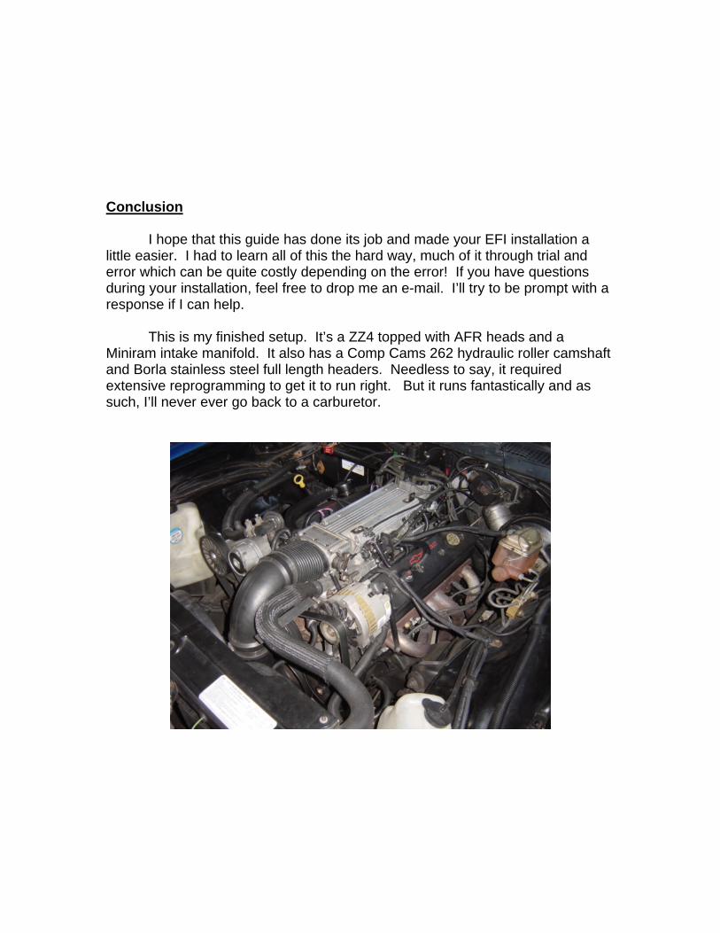
Conclusion I hope that this guide has done its job and made your EFI installation a little easier. I had to learn all of this the hard way, much of it through trial and error which can be quite costly depending on the error! If you have questions during your installation, feel free to drop me an e-mail. I’ll try to be prompt with a response if I can help.
This is my finished setup. It’s a ZZ4 topped with AFR heads and a Miniram intake manifold. It also has a Comp Cams 262 hydraulic roller camshaft and Borla stainless steel full length headers. Needless to say, it required extensive reprogramming to get it to run right. But it runs fantastically and as such, I’ll never ever go back to a carburetor.