telorvek efi 4.6 sequential fuel injection system … sequential fuel injection system mk-97a ......
TRANSCRIPT

Page #1
TELORVEK EFI
4.6 Sequential Fuel Injection
System MK-97A
WIRING INSTRUCTIONS
Thank you for purchasing the absolute finest of wiring kits for the Ford Motor Co. 4.6. Thisharness works with 1999 and newer Ford Mustang 4.6 and other select late model 4.6 & 5.4 2Vand 4V fuel injection engines. We have taken considerable time to work out the circuitry so thatyou, the customer will understand at least some of what this is all about. We ask that you followour instructions closely.
These engines originally used a “returnless” fuel system. The ECM maintained a fuel pump thatwas equipped to operate at variable speeds. A Constant Control Relay Module (CCRM), a FuelPump Driver Module, an in tank and fuel rail pressure transducer were all incorporated incalibrating this system. (If you plan to use these components, this has been discussed withour technicians and we have worked with you accordingly) Typically, for ease ofinstallation, we eliminate the need for all of these components and have included fuel pumprelay wiring in this harness. However, to maintain proper fuel pressure a return line must beused. There are several companies who offer fuel rails that adapt a return line system or youmay develop a short return line system with a pressure regulator back near the tank. Theseengines require 32-33 PSI at idle and 41-42 PSI at WOT. We recommend that the pump bemounted in the fuel tank. Custom installations are available from Tanks Inc. (320-558-6882)and Rock Valley (800-344-1934).
NOTE: FORD diagnostic procedures are very detailed, lengthy and impossible to cover in thisset of instructions. Purchasing the FORD ENGINE/ EMISSIONS DIAGNOSIS shop manual willhelp you learn about the engine you installed and guide you through the correct diagnosticprocedures Ford recommends. This book is available through your local Ford dealer orHelm Inc. Helm is the distributor for the shop manuals for General Motors and FordMotor Company. Helm can be contacted at 800-782-4356 or on their web sitewww.helminc.com
***Note***The ECM for this engine must be reprogrammed to have the PATS anti-theftremoved, along with other necessary changes. This was explained to you at thetime of order. If you have not had the ECM reprogrammed or have anyquestions please call us at 610-485-1981.
Page #2
WARNING!After the kit installation is complete and it is necessary to diagnose a startingor drive ability problem, follow the procedures recommended in the shopmanual. All voltage tests must be preformed using a HIGH impedance, digitalvoltmeter. DO NOT use a test light on this system! DAMAGE WILL BE DONEto the engine computer if a test light is used on this system.
STARTING INSTALLATION
Since there are so many individual circuits to complete, we recommend that you connect them in the order that we
prescribe. Disconnect the battery before starting and do not reconnect until instructed.
There will be many connections to the TELORVEK panel so plan the location of the panel in an area with room to
work. W e suggest mounting the panel in an assessable location, in the trunk, under the seat or under the dash are
good. In order to allow for the proper spacing between the computer and the Telorvek panel, plug the connector
into the computer (ECM) and mount the panel and computer. For safety, disconnect the ECM connector until
finished the installation. A poor installation will result in a poor running car. The number referred to from this
point on will be the location on one of the terminal blocks located on the TELORVEK panel.
After all wires are connected to the engine, wire tie them together or use 3/4 inch Zip loom to protect them. This can
be done before any connections are made to the panel. Since all wires are marked, running the entire group to the
panel at one time is fine. Some terminals on the panel may not be used!
Important! W e have supplied three sizes of terminals for your use on the panels itself. The Yellow is for 10-12
gauge wire, Blue for 14-16 gauge wire and red for 18 gauge wire. Each individual bag instructions will be marked as
to which terminal to use.
L NOTE 7You will be moving around to different terminals on the TELORVEK panel tomake connections. For this reason extra care is needed when making allconnections to the panel.
Bag #60 MASS AIR FLOW SENSOR: Attach the connector to the M.A.F sensor located in the air intake tube
between the intake manifold and air cleaner. Using a blue terminal run the Red wire (MAF->23) to #23. Now using
the red terminals run the Black (MAF->24) to #24, Tan (MAF->2) to #2 and Lt Blue (MAF->1) to #1.
Bag #60A MASS AIR FLOW & INTAKE AIR SENSOR (select models): Attach the connector to the M.A.F
sensor located in the air intake tube between the intake manifold and air cleaner. Using a blue terminal run the Red
wire (MAF->23) to #23. Using the red terminals run the Black (MAF->24) to #24, Tan (MAF->2) to #2, Lt Blue
(MAF->1) to #1, Lt Green wire (IAT->7) to #7 and the Gray wire (IAT->32) to #32.
Bag #61 EXHAUST GAS RECIRCULATION VALVE POSITION SENSOR: This wiring is not included if it
has been eliminated from the ECM programming. Plug in the connector to the EGRVP located on the left rear of the
engine. Using red terminals run the W hite wire (EGRVP->4) to #4, Brown wire (EGRVP->3) to #3 and the Gray
(EGRVP->31) to #31.
Bag #62 THROTTLE POSITION SENSOR (TPS): Plug into the sensor located in the rear of the engine on
the throttle body and run the wires back to the panel. Using the red terminals run the Dark Blue (TPS->6) to #6,
W hite (TPS->4) to #4 and Gray (TPS->31) to #31.
Bag #63 INTAKE AIR TEMPERATURE SENSOR (IAT) - Included in Bag 60A for some models: Plug
the connector onto the IAT sensor located on the top rear of the engine near the throttle body. Run the wires to the
Telorvek Panel and using the red terminals connect the Lt Green wire (IAT->7) to #7 and the Gray wire (IAT->32) to
#32.
Page #3
Bag #64B INTAKE MANIFOLD RUNNER CONTROL MONITOR/SOLENOID (IMRC): TRUCKS ONLY The IMRC is located on the top of the engine. Plug in the connector and run the wires back to the Telorvek panel.
Connect the Red wire (IMRC SOL->23) to #23 and the Lt Green wire (IMRC SOL->8) to #8.
Bag #65A KNOCK SENSORS (2) (Mach 1 & Non S/C Cobra 4V only): Plug the connectors into the knock
sensors and run the wires back to the panel. Using the red terminals, connect the Dk Green (RT KNOCK ->10) to
#10, Yellow wire (RT KNOCK->11) to #11, the Tan wire (LF KNOCK->108) to #108 and the Dk Green (LF KNOCK -
> 109) to 109.
Bag #65B KNOCK SENSOR (1) (Marauder, Trucks and Navigator only): Plug connector together and
run the wires back to the panel. Using the red terminals, connect the Dk Green (RT KNOCK ->10) to #10 and the
Yellow wire (RT KNOCK->11) to #11.
Bag #67 EGR SOLENOID: This wiring is not included if it has been eliminated from the ECM programming.
Plug the connector into the EGR solenoid located on the left rear of the engine. Using a the red terminals run the
Red wire (EGR SOL->22 to #22 and the Brown wire (EGR SOL->14) to #14.
Bag #68 OXYGEN SENSOR (4): Ford now uses four heated O2 sensors. This area of the vehicle is hot so
keep the wires away from the exhaust. Four sensors are required per engine. Install the left and right front O2
sensors in each exhaust manifold or in the header collector as close to the block as possible. The left and
right rear O2 sensors mount behind the catalytic converters in each exhaust pipe. These sensors monitor the
status of the converters and W ILL set a trouble code if a faulty converter is detected or a converter is not used at all
(UNLESS YOU HAVE HAD YOUR COMPUTER REPROGRAMMED). NOTE: The O2 sensors do not send a
signal to the ECM until they reach 600 degrees. Mounting them in header collectors may take longer for them to
heat up causing the ECM to stay in OPEN LOOP longer than normal. If you must install an adapter, use part # OS-
30.
LEFT FRONT O2: The four gang connector with the Red, Dk Blue, Yellow and Gray wires running from it plugs into
the left front oxygen sensor.
RIGHT FRONT O2: The four gang connector with the Red, Lt Blue, W hite and Gray wires running from it plugs into
the right front oxygen sensor.
LEFT REAR O2: The four gang connector with the Red, Lt Green, W hite and Gray wires running from it plugs into
the left rear oxygen sensor.
RIGHT REAR O2: The four gang connector with the Red, Purple, Tan and Gray wires running from it plugs into the
right rear oxygen sensor.
Run all the wires back to the panel and using the blue terminals connect the Red wires (LEFT FRT O2->22) to #22,
(RIGHT FRT O2->21) to #21, Red wires (RIGHT RR O2->101) & (LEFT RR O2->101) to #101. The Gray wires
(LEFT FRT O2->34) to #34, (LEFT RR O2->38) to #38, (RIGHT FRT O2->35) to #35 & (RIGHT RR O2->38) to
#38. Now using the red terminals connect the Dk Blue (LEFT FRT O2->16) to #16, Yellow (LEFT FRT O2->15) to
#15, Lt Blue (RIGHT FRT O2->18) to #18, W hite (RIGHT FRT O2->17) to #17, Purple (RIGHT RR O2->105) to
#105, Tan (RIGHT RR O2->106) to #106, Lt Green (LEFT RR O2->103) to #103 and the white (LEFT RR O2->104)
to #104.
Bag #70 and 70A IGNITION COIL: This 4.6 engine has eight coil packs, one for each spark plug. The coil
packs are located above each cylinder. Locate the right coil connector with the Red and Lt Green wires and connect
it to cylinder number (1) coil one (front passenger side). Now plug in the rest of the coil connectors (coils 2, 3, 4) in
that half of the harness. In the left coil harness locate the coil connector with the Red and Yellow wires and connect
it to injector number (5) (front driver side). Plug in the rest of the coil connectors (coils 6, 7, 8) and run all the wires
from both haves of the harness to the Telorvek Panel.

Page #4
Using the blue terminals connect the Red wires (IGN COIL 1->49) and (IGN COIL 5->49) to #49. Now connect the
remaining eight wires as follows using the red terminals, Lt Green (IGN COIL 1->41) to #41, Pink (IGN COIL 2->42)
to #42, W hite (IGN COIL 3->43) to #43, Dk Green (IGN COIL 4->44) to #44, Yellow (IGN COIL 5->45) to #45,
Orange (IGN COIL 6->46) to #46, Lt Blue (IGN COIL 7->47) to #47 and Dk Blue (IGN COIL 8->48) to #48.
WARNING !!!The distributorless ignition system (DIS) on this engine is a high energy systemoperating in a dangerous voltage range which could prove to be fatal if exposedterminals or live parts are contacted. Use extreme caution when working on the vehiclewith the ignition on or the engine running.
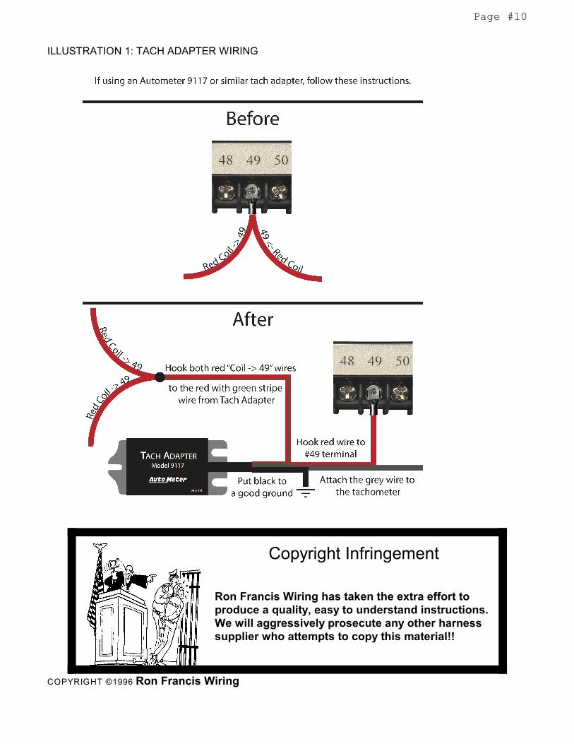
TACH: W ith these coil on plug motors Ford has the ECM providing the tach signal to the dash cluster. This tach
signal is delivered multiplexed with other data that only the original dash instruments can read. For this reason, if
you are using a tachometer, you will need to acquire a tach module or driver. Most gauge manufacturers have such
units as this is a common problem that every 1999 and newer Mustang owner encounters when attempting to install
an aftermarket tach. If you are using an Autometer Tach Adapter (part number 9117) or similar, see illustration 1 at
the end of these instructions for how to wire. Please consult your gauge manufacturer or give us a call to solve this
issue or help wire up a tach module/driver 610-485-1981.
Bag #71 and 71A INJECTORS: The injector wiring is made up in two harnesses, one for the left bank of
injectors and one for the right bank. Locate the right injector connector with the Red and Lt Green wires and connect
it to cylinder number (1) injector one (front passenger side). Now plug in the rest of the injector connectors (injectors
2, 3, 4) in that half of the harness. In the left injector harness locate the injector connector with the Red and Yellow
wires and connect it to injector number (5) (front driver side). Plug in the rest of the injector connectors (injectors 6,
7, 8) and run all the wires from both haves of the harness to the Telorvek Panel. Using the blue terminals connect
the Red wires (INJ 1->69) and (INJ 5->69) to #69. Now connect the remaining eight wires as follows using the red
terminals, Lt Green (INJ 1->61) to #61, Pink (INJ 2->62) to #62, W hite (INJ 3->63) to #63, Dk Green (INJ 4->64) to
#64, Yellow (INJ 5->65) to #65, Orange (INJ 6->66) to #66, Lt Blue (INJ 7->67) to #67 and Dk Blue (INJ 8->68) to
#68.
Bag #72 IDLE SPEED CONTROL: The ISC is located on the rear of the engine in the throttle body. Plug in the
connector and run the wires back to the panel. Using the red terminals, connect the W hite wire (ISC->70) to #70
and the Red wire (ISC->21) to #21.
Bag #73 COOLANT TEMPERATURE SENSOR (AIR INTAKE SENSOR NUMBER 2 IN SOME
APPLICATIONS): If your application does not have an engine coolant sensor, you will have a second air intake
sensor. After attaching the plug to the sensor run the two wires to the panel. Connect them using the red terminals,
Lt Green wire (ECT->71) to #71 and the Gray wire (ECT->35) to #35.
Bag #74 and 74A CAMSHAFT POSITION SENSOR (CSP): requires the wires to be shielded from any
electrical interference. Carefully uncoil the harness and plug it into the CSP located on the left front of the engine.
Run the wires to the Telorvek panel. Remove the tape and shielding material back only as far as it is necessary for
the length of the wire to be cut and allowing enough wire to make the connections on the panel. In the shielded
harness there is a solid strand wire with no insulation, install a blue terminal on it and connect it to #26. After the
connection is made wrap the exposed wire from the shielded harness to #26 with electrical tape. Connect the
remaining two wires as follows: Dk Blue (CAM POS SEN->72) to #72 and the Gray (CAM POS SEN->36) to #36.
Bag #75 and 75A CRANK POSITION SENSOR (CPS): requires the wires to be shielded from any electrical
interference. Carefully uncoil the harness and plug it into the CPS located on the right front of the engine down by
the balancer. Run the wires to the Telorvek panel. Remove the tape and shielding material back only as far as it is
necessary for the length of the wire to be cut and allowing enough wire to make the connections on the panel. In the
shielded harness there is a solid strand wire with no insulation, install a blue terminal on it and connect it to #26.
After the connection is made wrap the exposed wire from the shielded harness to #26 with electrical tape. Connect
the remaining two wires as follows: Black wire (CPS->73) to #73 and the Gray wire (CPS->74) to #74.
Page #5
4R70W / 4R100W Electronic Controlled Overdrive Transmission Wiring(Bags #76,76A or 76B and #77)
Bag #76 AODE / Early 4R70W TRANSMISSION CONNECTIONS: The 4R70W transmission
is a electronically controlled four speed automatic transmission. Plug the connector into the
transmission and run the wires to the Telorvek panel. Using the red terminals, connect the Gray
(TRANS 9->37) to #37, Orange wire (TRANS 1->79) to #79, Lt Blue (TRANS 3->80) to #80, Black
(TRANS 5->81 to #81, Purple (TRANS 6->82) to #82 and the W hite (TRANS 10->83) to #83 . Using
blue terminals, connect the Red (TRANS 2->50) to #50, Red (TRANS 7->50) to #50 and the Red
(TRANS 8->51) to #51. The Purple wire (88->BRAKE SW ) connects to #88 and runs to the cold side
of the brake light switch. This wire should only have 12 volts with the brake pedal depressed.
Bag #76A Late 4R70W TRANSMISSION CONNECTIONS: These transmissions are
electronically controlled four speed automatic transmission. Plug the connector into the transmission
and run the wires to the Telorvek panel. Using the red terminals, connect the Gray wire (TRANS 2-
>37) to #37, Orange wire (TRANS 7->79) to #79, Lt Blue (TRANS 3->80) to #80, Black (TRANS 5->81
to #81, Purple (TRANS 8->82) to #82 and the W hite (TRANS 6->83) to #83 . Using blue terminals,
connect the Red (TRANS 4->50) to #50. The Purple wire (88->BRAKE SW ) connects to #88 and runs
to the cold side of the brake light switch. This wire should only have 12 volts with the brake pedal
depressed.
Bag #76B 4R100W TRANSMISSION CONNECTIONS: These transmissions are electronically
controlled heavy duty four speed automatic transmission. Plug the connector into the transmission
and run the wires to the Telorvek panel. Using the red terminals, connect the Gray wire (TRANS 8-
>37) to #37, Orange wire (TRANS 3->79) to #79, Lt Blue (TRANS 4->80) to #80, Brown (TRANS 5-
>119) to #119, Black (TRANS 7->81) to #81, Purple (TRANS 2->82) to #82 and the W hite (TRANS
11->83) to #83 . Using blue terminals, connect the Red (TRANS 1->50) to #50 and the Red (TRANS
12->50) to #50. The Purple wire (88->BRAKE SW ) connects to #88 and runs to the cold side of the
brake light switch. This wire should only have 12 volts with the brake pedal depressed.
Bag #77 DIGITAL TRANSMISSION RANGE SELECTOR : This switch is located on the left
hand side of the transmission. The DTR controls neutral safety, back-up and lever position functions.
W e have included wires in the MLPS connector to allow you to get full use out of the switch. If you
have an AODE or early 4R70W with the Manual Level Position Switch (MLPS) and are using it with
this late model 4.6 ECM you must upgrade to this Digital Trans Range Selector.
Connect the circuits in the switch as follows:
NEUTRAL / SAFETY: The heavier gauge Lt Blue (DTR 12 -> IGN SW ) and the Purple (DTR 10
-> START SOL) wires are for the neutral safety circuit. Locate the wire that runs from the ignition
switch to the starter solenoid. Cut the wire and connect the Lt Blue wire (DTR 12 -> IGN SW ) to the
wire running from the ignition switch and the Purple wire (DTR 10 -> START SOL) to the wire running
from the starter solenoid. NOTE: If you are wiring this circuit to a Ron Francis W ire W orks W iring Kit,
these wires will be a color for color match.
BACK-UP LIGHTS: Connect the Orange wire (BACK UP LT FEED) to a 12 volt ignition source. This
wire should have 12 volts only with the key in the run position. Run the other Dk Green wire (BACK
UP LTS) to the rear of the vehicle and connect it to both back-up lights. The lights must be grounded.
LEVER POSITION CIRCUIT: Run these wires to the Telorvek panel. Using the red terminals, connect
the Gray wire (DTR 2 -> 36) to #36, Lt Blue wire (DTR 3 -> 76) to #76, Yellow wire (DTR 4 -> 78) to
#78, Black wire (DTR 5 -> 77) to #77 and the W hite wire (DTR 6 -> 75) to #75.

Page #6
Bag #79 (For Automatic and Manual Applications) TRANSMISSION SPEED SENSOR: On automatics,
the transmission speed sensor is located on the left of the transmission case. This sensor combined with other
sensors inputs determine proper shift points and torque converter lock-up.
On late model manual applications, the transmission speed sensor is located near the tail shaft of the transmission
case.
After plugging in the connector run the wires back to the panel. Connect the Dk Blue wire (TRANS SPD SEN->85)
to #85 and the Gray wire (TRANS SPD SEN->37) to #37.
Electronic speedometers can be connected to terminal #86 to pick up the VSS signal. This is a standard Ford 8000
pulse per mile signal.
Bag #80 (Your Transmission May Not Have This Sensor) VEHICLE SPEED SENSOR: Install the
connector onto the speed sensor located in the speedometer assembly on the transmission and run the wires back
to the Telorvek panel. Using the red terminals connect the Gray wire (VEH SPD SEN->86) to #86 and the Black wire
(VEH SPD SEN->59) to #59.
Electronic speedometers can be connected to terminal #86 to pick up the VSS signal. This is a standard Ford 8000
pulse per mile signal.
Bag #80B (4R100W Truck Trans Only) TURBINE SHAFT SPEED SENSOR: Install the connector onto
the speed sensor located in the transmission and run the wires back to the Telorvek panel. Using the red terminals
connect the Gray wire (VEH SPD SEN->39) to #39 and the Black wire (VEH SPD SEN->54) to #54.
Electronic speedometers can be connected to terminal #86 to pick up the VSS signal. This is a standard Ford 8000
pulse per mile signal.
Bag #81 FUEL PUMP & INERTIA SWITCH: W e have included the wiring necessary for the Ford inertia
switch. The inertia switch cuts off the electric fuel pump in the advent of an accident. Mount the inertia switch in the
rear of the vehicle in a dry area. Using the blue terminals, plug in the connector to the inertia switch and run the Tan
wires (INERTIA SW ->98) to #98 and (INERTIA SW ->99) to #99 on the Telorvek panel. Run the other Tan wire (98-
>PUMP) to the electric fuel pump (This wire is not used if you are using the original FUEL PUMP MODULE
AND FUEL PUMP). Hook the wire to the positive terminal on the pump. From the negative terminal on the pump
connect a wire and run it to a good ground.
There are two loose wires in this package of wires. These two wires only get connected IF YOU ARE RUNNING A
FUEL SYSTEM W ITH A FUEL PRESSURE REGULATOR AND RETURN LINE. Connect the short Tan jumper
wire 95->99 to terminals 95 and 99. Then connect the Black jumper wire 94->29 to terminals 94 and 29. AGAIN,
ONLY INSTALL THESE WIRES IF YOU RUNNING A RETURN LINE. DISCARD THESE TWO WIRES IF YOU
ARE RUNNING A FACTORY RETURNLESS FUEL SYSTEM.
NOTE 1: The inertia switch has a red button on top of it that must be set (pushed down) in order for the fuel pump to
operate. If the pump fails to operate check the inertia switch making sure the red button is in the down position.
NOTE 2: There are two relay sockets in the cover of the panel. The one closest to the fuses is for the fuel pump
relay. Relays are not supplied with our wiring kit. The proper can be ordered locally under Airtex part #1R1061,
Standard Motor Products part #RY116 or GM part #14100455.
Bag #82A VARIABLE LOAD CONTROL RELAY MODULE (Certain Models Only) : This module
controls operation of the multi-speed fuel pump, electric cooling fans as well as other functions that will not be used
in a aftermarket application. This module is unique for the 1996 and newer models. The 1993-95 module will not
work in this application. Please be sure to use the correct year module.
Mount the VLCM within thirty inches of the Telorvek panel. Plug the connector into the VLCM and connect the wires
to the panel as follows:
Page #7
WARNING!Following the Ford wiring color coding for this connector, Ford called for theuse of the same color wire to be used more than once in the connector. Readthe printing on the wires carefully before any connections are made to theTelorvek panel.
Using blue terminals connect the Lt Blue (VLCM 1->114) to #114, Lt Blue (VLCM 2->114) to #114,Yellow (VLCM 3->112) to #112, Tan (VLCM 5->98) to #98, Yellow (VLCM 8->19) to #19, Red (VLCM 12->102) to #102, Dk Blue (VLCM14->110) to #110, Black (VLCM 15->29) to #29, Black (VLCM 16->30) to#30, Dk Blue (VLCM 17->110) TO #110 and Black (VLCM 18->30) to #30.
ELECTRIC FAN WIRING:Connect the Lt Blue wire (113->COOLING FAN) to terminal #113 and the Black wire (30->FAN GRND)to terminal #30 on the panel and run them to the electric radiator cooling fan. Connect the Lt Blue wireto the positive wire running from the fan motor and the other wire to the fan motor ground.
NOTE 1: IF YOUR APPLICATION IS A 2003-2004 CROWN VIC OR GRAN MARQUIS AND YOU ARE USING
THE LATE MODEL FORD FAN ASSEMBLY THAT CAME ORIGINAL ON THE DONOR VEHICLE, DO NOT
WIRE UP THE FAN PRESCRIBED ABOVE. INSTEAD, USING THE DONOR VEHICLE MODULE, RUN LARGE
GAUGE WIRES FROM THE MODULE TO THE BATTERY POWER AND GROUND. THEN, FOR THE SMALL
GAUGE WIRE, RUN TO TERMINAL 112 OF THE TELORVEK PANEL. DO NOT INSTALL A RELAY IN THE
ELECTRIC FAN RELAY PORT ON THE PANEL.
NOTE 2: There are two relay sockets in the cover of the panel. The one farthest from the fuses is for the electric fan
relay. Relays are not supplied with our wiring kit. The proper can be ordered locally under Airtex part #1R1061,
Standard Motor Products part #RY116 or GM part #14100455.
Bag #83 DATA LINK CONNECTOR (DLC): Mount the connector inside the vehicle under the dash. Now run
the wires to the Telorvek Panel and using the red terminals connect the Tan (DLC 2->118) to #118, Yellow (DLC 16-
>20) to #20, Pink (DLC 10->117) to #117, Purple (DLC 13->116) to #116 and the Black wires (DLC 4->28) & (DLC
5->28) to #28.
The remaining Lt Green & Red wires are for the dash mounted service engine soon (S.E.S) light. The light must be
a two wire un-grounded light. Connect the Lt Green wire (115->MIL LT) to #115 on the Telorvek Panel and run it to
a dash indicator light and connect it to one of the wires running from the light. The red wire (53->MIL LT) connects
to #53 on the panel and run to the other wire running from the light. This light is not required as the light on top of
the Telorvek Panel has the same function.
Bag #85 SUPERCHARGER BYPASS SOLENOID (Factory S/C Engines Only): This sensor is located on
the front top driver’s side of the engine. Plug in the connector and run the wires back to the panel. Using the red
terminals, connect the Purple wire (SC BP SOL 1->111) to #111 and the Red wire (SC BP SOL 2->23) to #23.
Bag #86 BAROMETRIC AIR PRESSURE SENSOR (Factory S/C Engines Only): This sensor is located
on the rear top driver’s side of the engine. Plug in the connector and run the wires back to the panel. Using the red
terminals, connect the Dk Blue wire (BAP 1->55) to #55, the W hite wire (BAP 2->5) to #5, the Red wire (BAP 3->81)
to #81 and the Grey wire (BAP 4->34) to #34. Some applications will have a three wire connector and will not
include the red wire.
Bag #88 FUEL PUMP DRIVER MODULE (Optional) : This unit is only used if you plan to use the stock fuel
pump. This system requires you to use the original fuel pump driver module and additional sensors.
Locate the fuel pump driver module to your liking and plug in the connector. Run the wires back to the panel. Using
the red terminals, connect the Lt Blue wire (FP DRIVE 1->94) to #94 and the Tan wire (FP DRIVE 7->95) to #95.
Using the blue terminals, connect the Black wire (FP DRIVE 2->27) to #27, Tan wire (FP DRIVE 3->96) to #96, the
Tan wire (FP DRIVE 9->98) to #98 and the Black wire (FP DRIVE 10->97) to #97.
Page #8
Next plug the 8 gang round connector into the fuel tank connector and run the wires back to the panel. There may
be a short black wire with a ground ring that needs to go to ground. Using blue connectors, connect the Tan wire
(FP MOTOR->96) to #96 and the Black wire (FP MOTOR->97) to #97. Using Red terminals, connect the red wire
(TANK PRESS->91) to #91, the Gray wire (TANK PRESS->32) to #32 and the white wire (TANK PRESS->5) to #5.
Using a red terminal, connect the Lt Green wire (FUEL SEND->100) to #100. If you are using the stock sending unit
in the fuel tank, we have supplied you with an additional Lt Green wire to run from #100 to your Fuel Gauge.
Bag #89 FUEL RAIL PRESSURE TRANSDUCER (Optional): This sensor is only used if you are using the
above BAG 88 with the Fuel Pump Driver Module, etc. Locate the sensor on the front top driver’s side of the motor
on the fuel rail. Plug in the connector and run the wires back to the panel. Using the red terminals, connect the
W hite wire (FUEL PRESS->5) to #5, the Grey wire (FUEL PRESS->32) to #32 and the Red wire (FUEL PRESS-
>58) to #58.
Bag #90 CYLINDER HEAD TEMPERATURE SENSOR (Certain Models Only): This sensor is located in
one of the cylinder heads and may have a short piece of adapter harness. Plug in the connector and run the wires
back to the panel. Using the red terminals, connect the Grey wire (CHT->32) to #32 and the Yellow wire (CHT-120)
to #120.
Bag #91 CANISTER PURGE AND CANISTER VENT SENSORS (Certain Models Only): This wiring is
not included if it has been eliminated from the ECM programming. Plug in the connector into each sensor and run
the wires back to the panel. Using the red terminals, connect the Red wire (CAN VENT->52) to #52, the Purple wire
(CAN VENT->93) to #93, the light green wire (CAN PURGE->92) to #92 and the Red wire (CAN PURGE->52) to
#52.
FINISHING UP
Connect the large pre-wired orange wire to the ignition circuit of your ignition switch. This is an ignition feed that is
controlled by the ignition switch. This is not an accessory feed and must remain hot even when the engine is
cranking.
Connect the large pre-wired red battery feed wire to a battery feed. This is a battery feed that must remain hot even
with the key off. Make sure this is a good connection. If you have a Master Disconnect switch, install this wire on
the battery side of the switch so it will remain hot with the Disconnect off.
The black ground wire from the TELORVEK Panel runs direct to the battery. Run the battery ground directly to the
engine not the frame first.This includes rear mounted batteries.
STARTING THE ENGINE
You have now made all of the connections necessary to TRY to start your car. If you try now, you will be
disappointed since you did not hook up the battery. You can do so now.
We're trying...
Ron Francis W iring has made every effort to assure a quality product and can assure you that this system works
well in your application. Most of the 'problem' calls we have had to date are basic trouble shooting questions which
have nothing to do with the TELORVEK system we sold you.
W e are committed to offering the most user friendly wiring systems available and support this with many years
experience in the wiring and fuel injection fields. Please be certain that all connections are correct and tests run
before calling. Your unit can be tested at any Ford Motor Company Dealership with no difficulty.

Page #9
Fuse Designation & Size
The harness has a total of eight fuses. Shown below is a diagram of what each fuse protects. The illustration is the
front view of the Telorvek panel.
Fuse Block #1 Fuse Block #2
FuseDesignation
Fuse SizeBlock #1
FuseDesignation
Fuse SizeBlock #2
Emission Equipment/VLCM 15 AMP Left & Right O2 Sensors 15 AMP
Mass Air Flow Sensor 15 AMP Emission Equipment 20 AMP
Left & Right Coils &Transmission
20 AMP Fuel Pump Relay 30 AMP
Left & Right Injectors 20 AMP VLCM & Fan Relay 30 AMP
FUEL PUMP and ELECTRIC FAN RELAYS
The relay housings mounted in the cover of the Telorvek panel is for the FUEL PUMP and ELECTRIC FAN. The
relays can be ordered under Airtex part #1R1061, Standard Motor Products part #RY116 or GM part #14100455.
FUEL PUMP
RELAY
ELECTRIC FANRELAY
Numbered terminal block cover strip reference.
The drawing below is for your reference on the correct positioning of the Telorvek fuel injection panelterminal block cover strips.
When connecting wires to the panel be sure the numbered terminals match the drawing below.
Page #10
ILLUSTRATION 1: TACH ADAPTER WIRING
Copyright Infringement
Ron Francis Wiring has taken the extra effort toproduce a quality, easy to understand instructions. We will aggressively prosecute any other harnesssupplier who attempts to copy this material!!
COPYRIGHT ©1996 Ron Francis Wiring