linearization guide for efi vutek/matan/reggiani...linearization wizard available to not only efi...
TRANSCRIPT
EFI Fiery™ XF / proServer Version 6.3
Fiery Wide Format Products
AUGUST 15th, 2016 – Version 4 © Copyright 2016 | ELECTRONICS FOR IMAGING INC 1 of 30
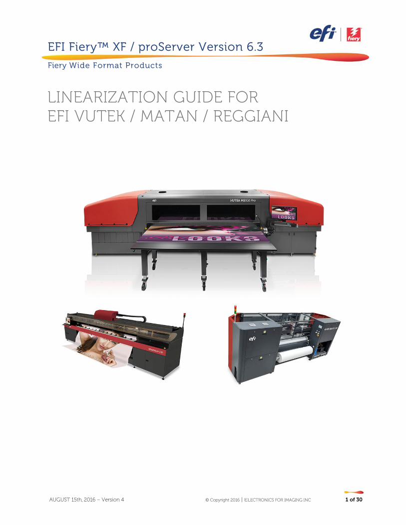
LINEARIZATION GUIDE FOR EFI VUTEK / MATAN / REGGIANI
AUGUST 15th, 2016 – Version 4 © Copyright 2016 | ELECTRONICS FOR IMAGING INC 2 of 30
Purpose of this document
This documentation will guide you through the process of creating a linearization and profile for your
EFI VUTEk, EFI Matan and/or EFI Reggiani printer. It will also provide hints on how to achieve specific
compromises between gamut size and ink saving.
Content A brief history of linearizations .......................................................................................................................................................................... 3 Linearization wizard ................................................................................................................................................................................................. 4
Step 1: Settings ........................................................................................................................................................................................................ 4 Step 2: Light norm ink build ........................................................................................................................................................................... 6 Step 3: Advanced ink limits .......................................................................................................................................................................... 10 Optional step: Gray balance ....................................................................................................................................................................... 16 Optional step: Quality Control ................................................................................................................................................................... 17 Step 4: Summary ................................................................................................................................................................................................ 18 Linearizing white ink & handling clear ink .........................................................................................................................................20
Creating a Media Profile ...................................................................................................................................................................................... 22 Black controls: ...................................................................................................................................................................................................... 23 Advanced black controls: ............................................................................................................................................................................. 24 Gamut mapping options: ............................................................................................................................................................................. 25 Processing options: .......................................................................................................................................................................................... 26 Extended gamut inks: ...................................................................................................................................................................................... 27 Profiler setting default values ..................................................................................................................................................................... 28
Hints on saving ink ................................................................................................................................................................................................. 30 Compatibility .............................................................................................................................................................................................................. 30
AUGUST 15th, 2016 – Version 4 © Copyright 2016 | ELECTRONICS FOR IMAGING INC 3 of 30
A brief history of linearizations When Fiery XF first started supporting EFI VUTEk printers in version 3, the same standard Fiery XF linearization was used as for any other printer. Later a dedicated Advanced VUTEk linearization was added with “Advanced” color modes for extended control of ink limiting and light/norm ink builds. It was implemented in parallel to the standard linearization, so that, for example, the “CMYK” color mode used the standard linearization, whereas “CMYK, Advanced” used the Advanced VUTEk linearization. Later still, all new EFI VUTEk printer drivers used only the Advanced VUTEk linearization, and the standard linearization was dropped altogether for these printers. Although the amount of control the 9-step Advanced VUTEk linearization wizard provided to customers was far superior to the standard linearization, the complexity and time it took to complete a linearization was increased as well. Fiery XF 6.1 has a completely new VUTEk linearization for the standard color modes (e.g “CMYK”). The wizard provides the same amount of control as the Advanced VUTEk linearization, but requires only 4 steps (+ 2 optional steps). This greatly reduces the complexity and time required to create a new linearization and, due to carefully chosen default values, even allows color novices to achieve excellent results quickly. Fiery XF 6.3 introduces a new advanced ink limit algorithm, new advanced ink limit charts and makes the linearization wizard available to not only EFI VUTEk, but also EFI Matan and EFI Reggiani printers. Additionally in Fiery XF 6.3 a new profiling engine was introduced for EFI Matan, EFI VUTEk and EFI Reggiani and offers new controls that will be explained towards the end of this document:
AUGUST 15th, 2016 – Version 4 © Copyright 2016 | ELECTRONICS FOR IMAGING INC 4 of 30
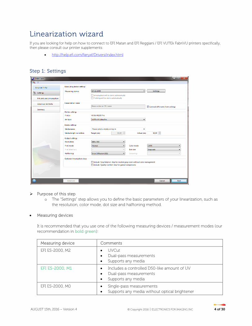
Linearization wizard If you are looking for help on how to connect to EFI Matan and EFI Reggiani / EFI VUTEk FabriVU printers specifically, then please consult our printer supplements:
• http://help.efi.com/fieryxf/Drivers/index.html
Step 1: Settings
Purpose of this step
o The “Settings” step allows you to define the basic parameters of your linearization, such as the resolution, color mode, dot size and halftoning method.
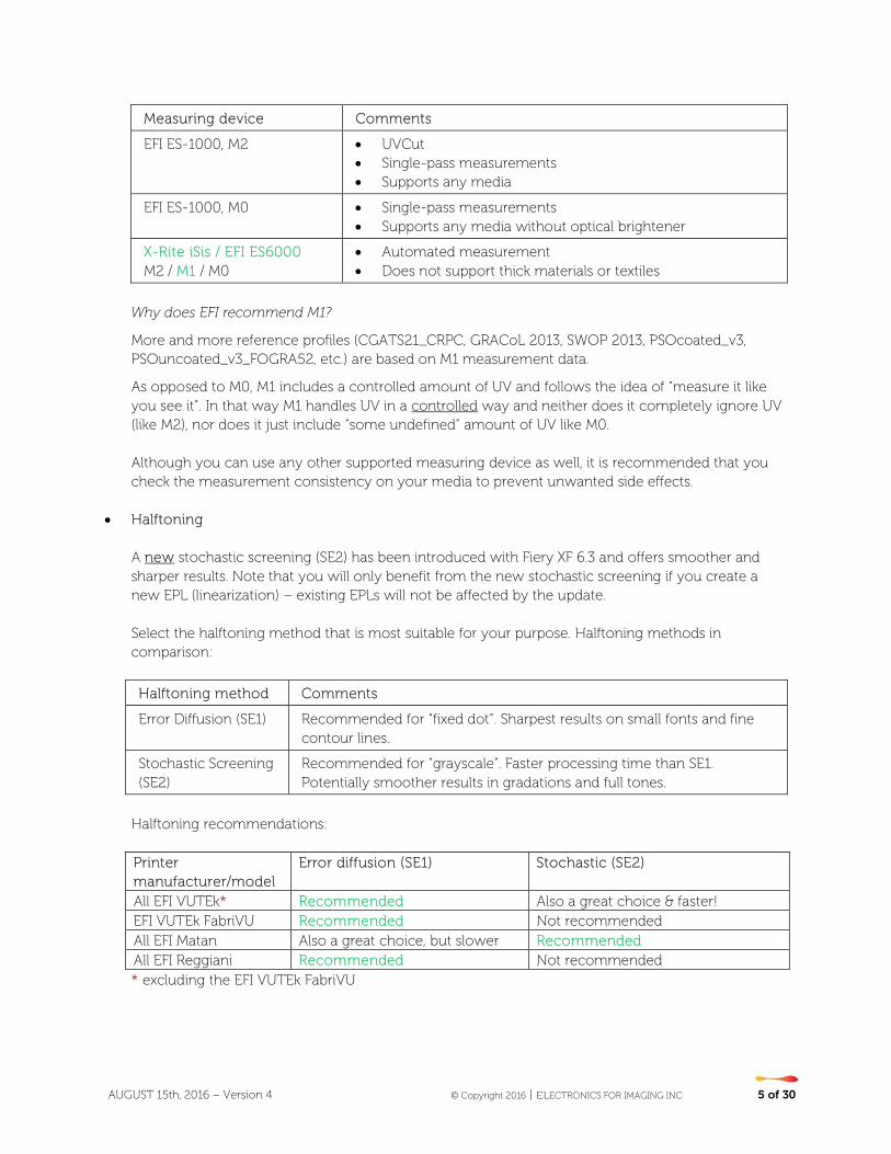
• Measuring devices
It is recommended that you use one of the following measuring devices / measurement modes (our recommendation in bold green):
Measuring device Comments
EFI ES-2000, M2 • UVCut • Dual-pass measurements • Supports any media
EFI ES-2000, M1 • Includes a controlled D50-like amount of UV • Dual-pass measurements • Supports any media
EFI ES-2000, M0 • Single-pass measurements • Supports any media without optical brightener
AUGUST 15th, 2016 – Version 4 © Copyright 2016 | ELECTRONICS FOR IMAGING INC 5 of 30
Measuring device Comments
EFI ES-1000, M2 • UVCut • Single-pass measurements • Supports any media
EFI ES-1000, M0 • Single-pass measurements • Supports any media without optical brightener
X-Rite iSis / EFI ES6000 M2 / M1 / M0
• Automated measurement • Does not support thick materials or textiles
Why does EFI recommend M1?
More and more reference profiles (CGATS21_CRPC, GRACoL 2013, SWOP 2013, PSOcoated_v3, PSOuncoated_v3_FOGRA52, etc.) are based on M1 measurement data.
As opposed to M0, M1 includes a controlled amount of UV and follows the idea of “measure it like you see it”. In that way M1 handles UV in a controlled way and neither does it completely ignore UV (like M2), nor does it just include “some undefined” amount of UV like M0. Although you can use any other supported measuring device as well, it is recommended that you check the measurement consistency on your media to prevent unwanted side effects.
• Halftoning
A new stochastic screening (SE2) has been introduced with Fiery XF 6.3 and offers smoother and sharper results. Note that you will only benefit from the new stochastic screening if you create a new EPL (linearization) – existing EPLs will not be affected by the update. Select the halftoning method that is most suitable for your purpose. Halftoning methods in comparison:
Halftoning method Comments
Error Diffusion (SE1) Recommended for “fixed dot”. Sharpest results on small fonts and fine contour lines.
Stochastic Screening (SE2)
Recommended for “grayscale”. Faster processing time than SE1. Potentially smoother results in gradations and full tones.
Halftoning recommendations:
Printer manufacturer/model
Error diffusion (SE1) Stochastic (SE2)
All EFI VUTEk* Recommended Also a great choice & faster! EFI VUTEk FabriVU Recommended Not recommended All EFI Matan Also a great choice, but slower Recommended All EFI Reggiani Recommended Not recommended * excluding the EFI VUTEk FabriVU
AUGUST 15th, 2016 – Version 4 © Copyright 2016 | ELECTRONICS FOR IMAGING INC 6 of 30
• Optional steps
The Fiery XF / Fiery proServer 6.3 linearization provides two optional steps:
o Include "Gray Balance" step for neutral grays even without color management o Include "Quality Control" step for gamut comparisons
Select the “Gray Balance” step if you want the linearization to balance the C, M and Y curves in such a way that they produce neutral grays even before the ICC profile is created. This step was introduced to help Color Profiler Suite achieve more neutral grays, but is typically no longer needed due to the updated linearization curve algorithms in Fiery XF 6.1+. It is recommended that you leave this check box unchecked if you want to save time, ink and media. Select the “Quality Control” step if you want to evaluate and/or compare the resulting gamut of your linearization before creating a profile (e.g. to change parameters before you decide to print the profiling target). By selecting this step, you can evaluate the gamut and optionally compare it to reference profiles such as GRACoL or ISOcoatedV2 or any custom profile (e.g. one of another EFI VUTEk printer) that you load. Also note that the linearization report will not include L*a*b* data for the solids if you do not choose to print & measure the “Quality Control” chart.
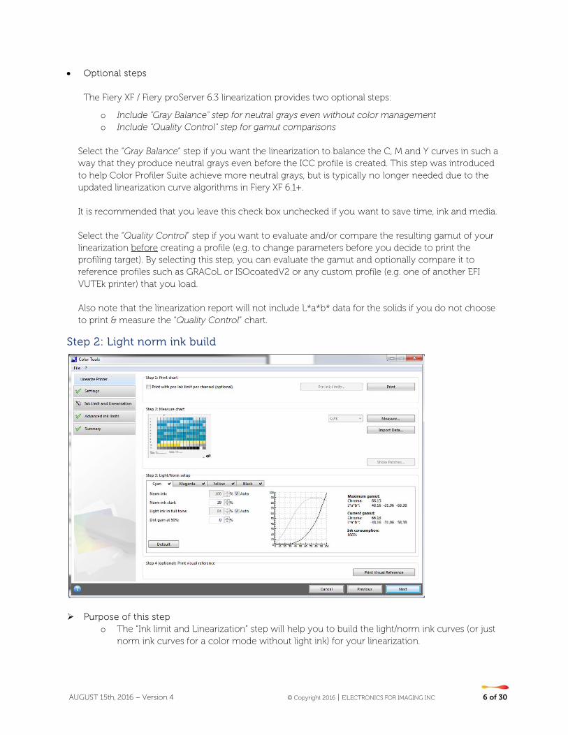
Step 2: Light norm ink build
Purpose of this step
o The “Ink limit and Linearization” step will help you to build the light/norm ink curves (or just norm ink curves for a color mode without light ink) for your linearization.

AUGUST 15th, 2016 – Version 4 © Copyright 2016 | ELECTRONICS FOR IMAGING INC 7 of 30
o Defining the behavior of light and norm ink linearization curves and ink limits is important for the gamut size and/or ink savings you may want to target.
The check box “Print with pre-ink limit per channel (optional)” is optional and allows you to define pre-ink limits before you start the linearization. Clicking the chain icon allows you to influence all ink limits at the same time.
Pre-ink limits are only useful if your printer/media combination cannot handle the full amount of inks, and bleeding, mottling or drastic ink thickness effects can be seen on your primary color gradations.
Important:
Pre-ink limits have been applied to all 1000 dpi resolutions so that the default gamut of 1000 dpi will match the gamut of 600dpi! This behavior was requested by many of users and allows you to align easily the color of 600 dpi and 1000 dpi resolution modes.
However, if you want to use the full gamut capabilities of the 1000 dpi mode (e.g. for backlit applications), reset all pre-ink limits for the 1000 dpi resolution to 100%!
If in doubt, leave this check box unchecked, as applying pre-ink limits to your channel(s) may noticeably reduce the gamut you can achieve with the linearization. Print and measure the newly designed light/norm charts.
AUGUST 15th, 2016 – Version 4 © Copyright 2016 | ELECTRONICS FOR IMAGING INC 8 of 30
Small check marks appear next to the channel name on each tab if measurement data is present. Use the displayed values for Chroma and L*a*b* on the right side of the Color Tools window to evaluate the “Maximum gamut” you can achieve with the current combination of printer, media and ink and compare it with the “Current gamut” you will achieve based on the settings you have chosen. These values provide reliable feedback if you want to achieve a certain compromise between ink saving and gamut size.
The “Ink consumption” value represents the approximate amount of ink used for the reproduction of a gradient from 0% to 100% of the selected input channel, taking the shape of the light- and norm ink and the pre-ink-limits into account.
• 100% is equivalent to an unlinearized input channel using norm ink only. • 200% is equivalent to an unlinearized input channel using a combination of light ink and norm
ink (= 100% light ink unlinearized + 100% norm ink unlinearized)." The default values of the linearization will automatically aim for the biggest possible gamut size. You can always return to the default settings by clicking “Default” on each ink channel tab. The following controls are available if you require advanced controls:
• Norm ink
o If the “Auto” check box is selected, the linearization automatically determines the amount of norm ink that is used to achieve the biggest possible gamut for this channel.
o Clearing “Auto” allows you to overwrite this value manually. o Note that the value (e.g, “85%”) is the maximum amount of norm ink you allow the
linearization to use – it is not an absolute value. In other words, a setting of “85%” would allow the linearization to use “up to 85%” norm ink. If the analysis of the measurement data shows that the maximum gamut could be achieved at 79%, then the linearization will choose a value of 79%. Evaluate the curve to the right to see how much norm ink is used. The dark colored curve is the norm ink curve.
• Norm ink start
o The ideal starting point of the norm ink curve is automatically determined by the linearization.
o You can review the color gradients on the “Visual Reference” chart, which you can print by clicking the appropriate button at the bottom of the Color Tools window. If necessary, you can change the transition point at which norm ink is added (e.g. because the bigger norm dots are kicking in too strongly), you can overwrite the default value.
o The “Norm ink start” value can also be used to save ink. By letting norm ink start sooner (lower values) you reduce the amount of light ink overall, but it may lead to grainy results.
o If you change the “Norm ink start”, make sure you avoid “flat curves”:

AUGUST 15th, 2016 – Version 4 © Copyright 2016 | ELECTRONICS FOR IMAGING INC 9 of 30
o If in doubt, do not change the default value!
• Light ink in full tone
o If the “Auto” check box is selected, the linearization automatically determines the amount of light ink in the full tone to achieve the biggest possible gamut for the channel.
o Clearing “Auto” allows you to overwrite this value manually. o Note that the value (e.g. “50%”) is the maximum amount of light ink you allow the
linearization to use in the full tone – it is not an absolute value. In other words, a setting of “50%” would allow the linearization to use “up to 50%” norm ink. If the analysis of the measurement data shows that the maximum gamut could be achieved at 10%, then the linearization will choose a value of 10%.
o You can use this setting to achieve a targeted compromise between maximum gamut (typically a greater amount of light ink the full tone) and ink saving. You can force the linearization not to use any light ink in the full tone at all by entering 0%.
o Recommendations: It is recommended to use similar light ink in full tone values for across all
channels that support light ink and to avoid extreme differences like 0% light ink for Cyan and 100% light ink for Magenta.
In general it is recommended to reduce the amount of light ink in full tone to avoid "pass to pass gloss banding". Up to 45% light ink tends to be reasonable.
• Dot gain at 50%
o The dot gain setting allows you to influence the C, M, Y and K curves individually if you want to add a certain dot gain to the linearized state.
o This can be useful in certain situations but, in general, it is recommended that you leave the value at 0%.
“Print visual reference” allows you to review your settings by evaluating the primary color gradations in a chart similar to the one illustrated below, e.g. for the CMYKOV color mode. The chart below is for CMYK:
Bad Good
AUGUST 15th, 2016 – Version 4 © Copyright 2016 | ELECTRONICS FOR IMAGING INC 10 of 30
Proceed to “Linearizing white ink” if you want to learn about how to linearize white ink.
Step 3: Advanced ink limits
Purpose of this step
o The “Advanced ink limit” step allows you to set 200%, 300% and/or 400% ink limits. o Its main target is to cut off gamut areas that are not needed or that can potentially cause
issues for profiling. In this step, start with printing the “Advanced ink limit” chart. The step is optional, but highly recommended. Note that two layouts are available.

AUGUST 15th, 2016 – Version 4 © Copyright 2016 | ELECTRONICS FOR IMAGING INC 11 of 30
Evaluate the chart to identify any need for 200%, 300% and/or 400% ink limiting.
AUGUST 15th, 2016 – Version 4 © Copyright 2016 | ELECTRONICS FOR IMAGING INC 12 of 30
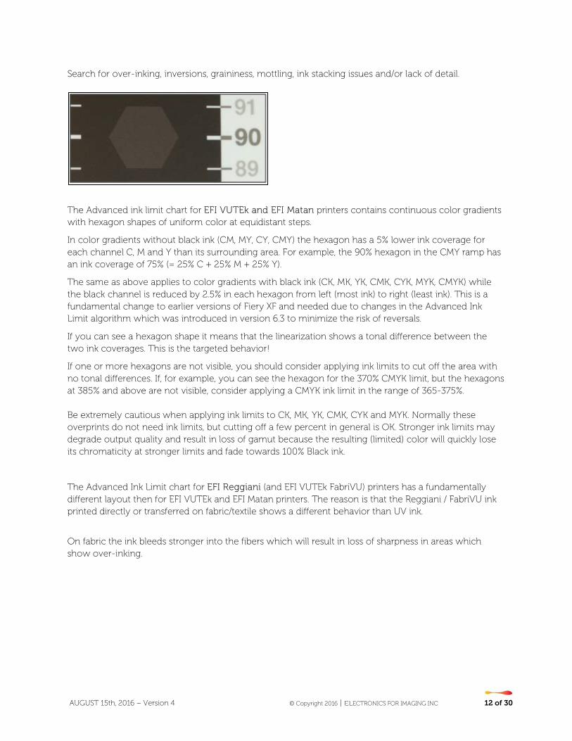
Search for over-inking, inversions, graininess, mottling, ink stacking issues and/or lack of detail.
The Advanced ink limit chart for EFI VUTEk and EFI Matan printers contains continuous color gradients with hexagon shapes of uniform color at equidistant steps.
In color gradients without black ink (CM, MY, CY, CMY) the hexagon has a 5% lower ink coverage for each channel C, M and Y than its surrounding area. For example, the 90% hexagon in the CMY ramp has an ink coverage of 75% (= 25% C + 25% M + 25% Y).
The same as above applies to color gradients with black ink (CK, MK, YK, CMK, CYK, MYK, CMYK) while the black channel is reduced by 2.5% in each hexagon from left (most ink) to right (least ink). This is a fundamental change to earlier versions of Fiery XF and needed due to changes in the Advanced Ink Limit algorithm which was introduced in version 6.3 to minimize the risk of reversals.
If you can see a hexagon shape it means that the linearization shows a tonal difference between the two ink coverages. This is the targeted behavior!
If one or more hexagons are not visible, you should consider applying ink limits to cut off the area with no tonal differences. If, for example, you can see the hexagon for the 370% CMYK limit, but the hexagons at 385% and above are not visible, consider applying a CMYK ink limit in the range of 365-375%. Be extremely cautious when applying ink limits to CK, MK, YK, CMK, CYK and MYK. Normally these overprints do not need ink limits, but cutting off a few percent in general is OK. Stronger ink limits may degrade output quality and result in loss of gamut because the resulting (limited) color will quickly lose its chromaticity at stronger limits and fade towards 100% Black ink.
The Advanced Ink Limit chart for EFI Reggiani (and EFI VUTEk FabriVU) printers has a fundamentally different layout then for EFI VUTEk and EFI Matan printers. The reason is that the Reggiani / FabriVU ink printed directly or transferred on fabric/textile shows a different behavior than UV ink.
On fabric the ink bleeds stronger into the fibers which will result in loss of sharpness in areas which show over-inking.
AUGUST 15th, 2016 – Version 4 © Copyright 2016 | ELECTRONICS FOR IMAGING INC 13 of 30
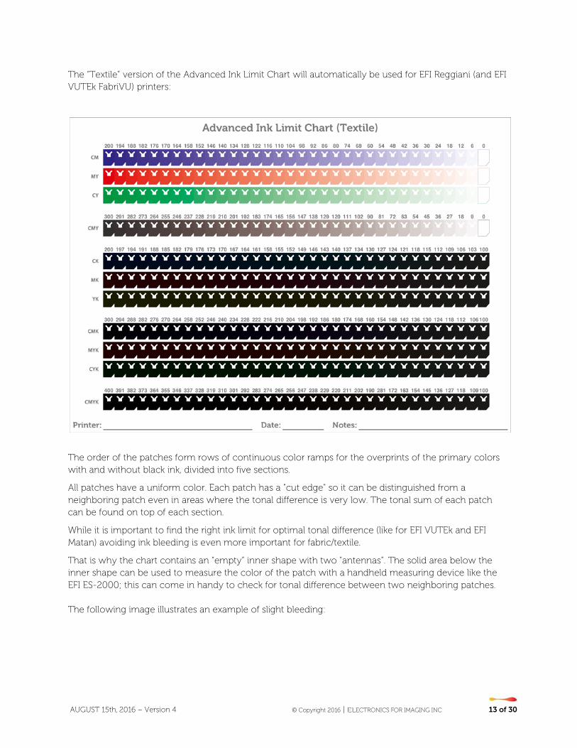
The “Textile” version of the Advanced Ink Limit Chart will automatically be used for EFI Reggiani (and EFI VUTEk FabriVU) printers:
The order of the patches form rows of continuous color ramps for the overprints of the primary colors with and without black ink, divided into five sections.
All patches have a uniform color. Each patch has a "cut edge" so it can be distinguished from a neighboring patch even in areas where the tonal difference is very low. The tonal sum of each patch can be found on top of each section.
While it is important to find the right ink limit for optimal tonal difference (like for EFI VUTEk and EFI Matan) avoiding ink bleeding is even more important for fabric/textile.
That is why the chart contains an “empty” inner shape with two "antennas”. The solid area below the inner shape can be used to measure the color of the patch with a handheld measuring device like the EFI ES-2000; this can come in handy to check for tonal difference between two neighboring patches. The following image illustrates an example of slight bleeding:
AUGUST 15th, 2016 – Version 4 © Copyright 2016 | ELECTRONICS FOR IMAGING INC 14 of 30
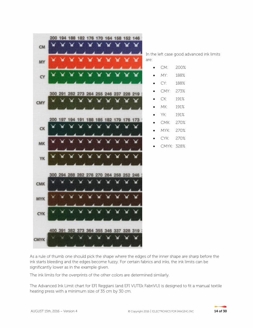
In the left case good advanced ink limits are:
• CM: 200%
• MY: 188%
• CY: 188%
• CMY: 273%
• CK: 191%
• MK: 191%
• YK: 191%
• CMK: 270%
• MYK: 270%
• CYK: 270%
• CMYK: 328%
As a rule of thumb one should pick the shape where the edges of the inner shape are sharp before the ink starts bleeding and the edges become fuzzy. For certain fabrics and inks, the ink limits can be significantly lower as in the example given.
The ink limits for the overprints of the other colors are determined similarly. The Advanced Ink Limit chart for EFI Reggiani (and EFI VUTEk FabriVU) is designed to fit a manual textile heating press with a minimum size of 35 cm by 30 cm.
AUGUST 15th, 2016 – Version 4 © Copyright 2016 | ELECTRONICS FOR IMAGING INC 15 of 30
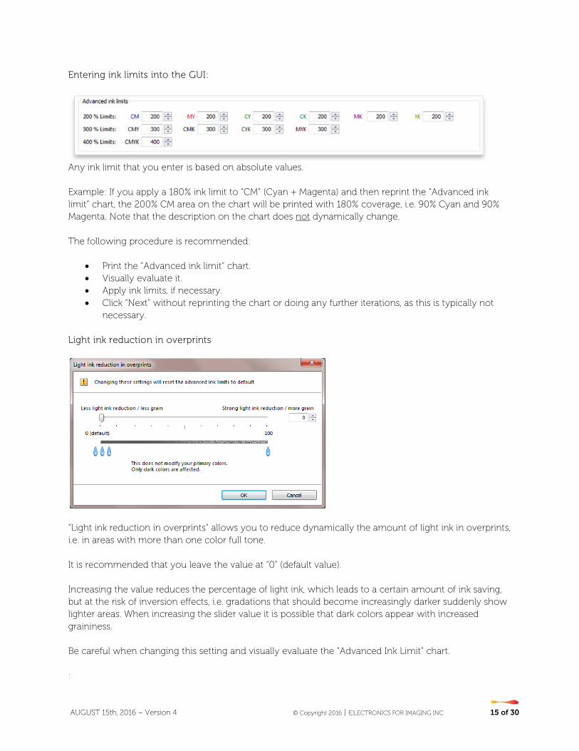
Entering ink limits into the GUI:
Any ink limit that you enter is based on absolute values. Example: If you apply a 180% ink limit to “CM” (Cyan + Magenta) and then reprint the “Advanced ink limit” chart, the 200% CM area on the chart will be printed with 180% coverage, i.e. 90% Cyan and 90% Magenta. Note that the description on the chart does not dynamically change. The following procedure is recommended:
• Print the “Advanced ink limit” chart. • Visually evaluate it. • Apply ink limits, if necessary. • Click “Next” without reprinting the chart or doing any further iterations, as this is typically not
necessary. Light ink reduction in overprints
“Light ink reduction in overprints” allows you to reduce dynamically the amount of light ink in overprints, i.e. in areas with more than one color full tone. It is recommended that you leave the value at “0” (default value). Increasing the value reduces the percentage of light ink, which leads to a certain amount of ink saving, but at the risk of inversion effects, i.e. gradations that should become increasingly darker suddenly show lighter areas. When increasing the slider value it is possible that dark colors appear with increased graininess. Be careful when changing this setting and visually evaluate the “Advanced Ink Limit” chart. :
AUGUST 15th, 2016 – Version 4 © Copyright 2016 | ELECTRONICS FOR IMAGING INC 16 of 30
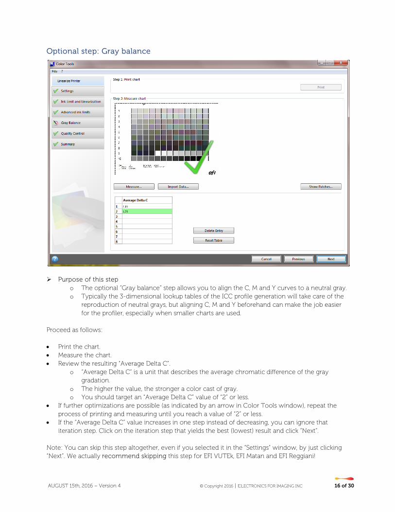
Optional step: Gray balance
Purpose of this step
o The optional “Gray balance” step allows you to align the C, M and Y curves to a neutral gray. o Typically the 3-dimensional lookup tables of the ICC profile generation will take care of the
reproduction of neutral grays, but aligning C, M and Y beforehand can make the job easier for the profiler, especially when smaller charts are used.
Proceed as follows: • Print the chart. • Measure the chart. • Review the resulting “Average Delta C”.
o “Average Delta C“ is a unit that describes the average chromatic difference of the gray gradation.
o The higher the value, the stronger a color cast of gray. o You should target an “Average Delta C” value of “2” or less.
• If further optimizations are possible (as indicated by an arrow in Color Tools window), repeat the process of printing and measuring until you reach a value of “2” or less.
• If the “Average Delta C” value increases in one step instead of decreasing, you can ignore that iteration step. Click on the iteration step that yields the best (lowest) result and click “Next”.
Note: You can skip this step altogether, even if you selected it in the “Settings” window, by just clicking “Next”. We actually recommend skipping this step for EFI VUTEk, EFI Matan and EFI Reggiani!
AUGUST 15th, 2016 – Version 4 © Copyright 2016 | ELECTRONICS FOR IMAGING INC 17 of 30
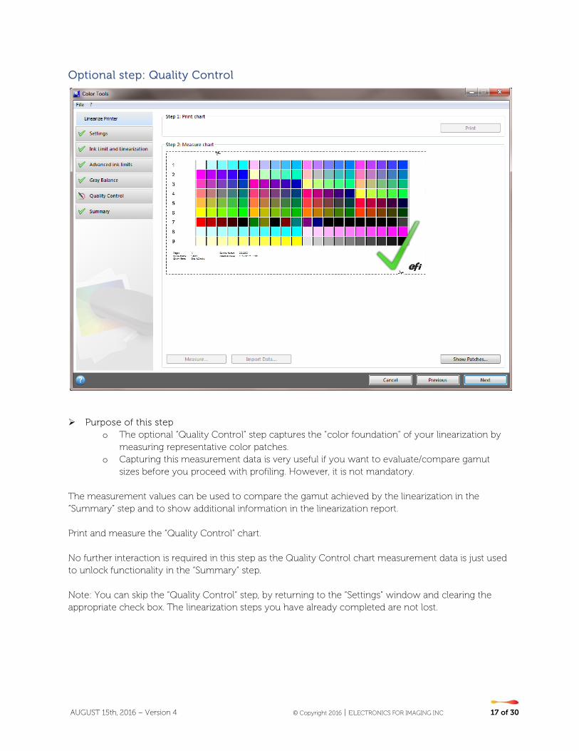
Optional step: Quality Control
Purpose of this step
o The optional “Quality Control” step captures the "color foundation" of your linearization by measuring representative color patches.
o Capturing this measurement data is very useful if you want to evaluate/compare gamut sizes before you proceed with profiling. However, it is not mandatory.
The measurement values can be used to compare the gamut achieved by the linearization in the “Summary” step and to show additional information in the linearization report. Print and measure the “Quality Control” chart. No further interaction is required in this step as the Quality Control chart measurement data is just used to unlock functionality in the “Summary” step. Note: You can skip the “Quality Control” step, by returning to the “Settings” window and clearing the appropriate check box. The linearization steps you have already completed are not lost.
AUGUST 15th, 2016 – Version 4 © Copyright 2016 | ELECTRONICS FOR IMAGING INC 18 of 30
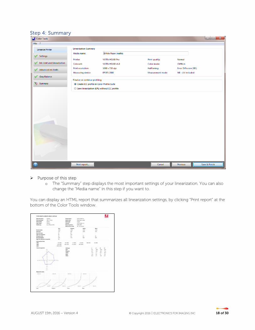
Step 4: Summary
Purpose of this step o The “Summary” step displays the most important settings of your linearization. You can also
change the “Media name” in this step if you want to. You can display an HTML report that summarizes all linearization settings, by clicking “Print report” at the bottom of the Color Tools window.
AUGUST 15th, 2016 – Version 4 © Copyright 2016 | ELECTRONICS FOR IMAGING INC 19 of 30
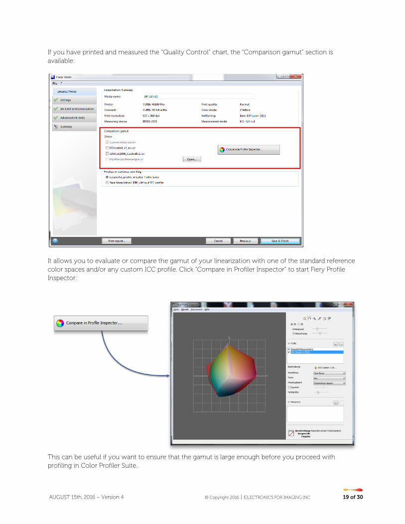
If you have printed and measured the “Quality Control” chart, the “Comparison gamut” section is available:
It allows you to evaluate or compare the gamut of your linearization with one of the standard reference color spaces and/or any custom ICC profile. Click “Compare in Profiler Inspector” to start Fiery Profile Inspector:
This can be useful if you want to ensure that the gamut is large enough before you proceed with profiling in Color Profiler Suite.
AUGUST 15th, 2016 – Version 4 © Copyright 2016 | ELECTRONICS FOR IMAGING INC 20 of 30
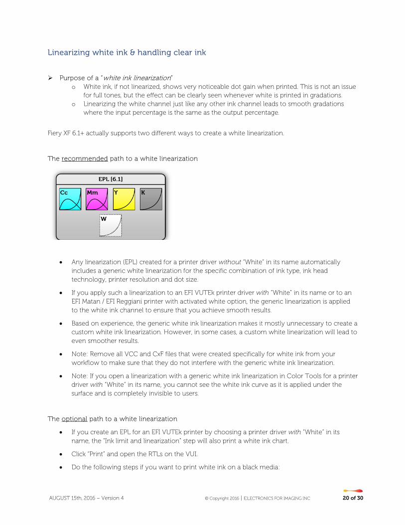
Linearizing white ink & handling clear ink
Purpose of a “white ink linearization”
o White ink, if not linearized, shows very noticeable dot gain when printed. This is not an issue for full tones, but the effect can be clearly seen whenever white is printed in gradations.
o Linearizing the white channel just like any other ink channel leads to smooth gradations where the input percentage is the same as the output percentage.
Fiery XF 6.1+ actually supports two different ways to create a white linearization.
The recommended path to a white linearization
• Any linearization (EPL) created for a printer driver without “White” in its name automatically includes a generic white linearization for the specific combination of ink type, ink head technology, printer resolution and dot size.
• If you apply such a linearization to an EFI VUTEk printer driver with “White” in its name or to an EFI Matan / EFI Reggiani printer with activated white option, the generic linearization is applied to the white ink channel to ensure that you achieve smooth results.
• Based on experience, the generic white ink linearization makes it mostly unnecessary to create a custom white ink linearization. However, in some cases, a custom white linearization will lead to even smoother results.
• Note: Remove all VCC and CxF files that were created specifically for white ink from your workflow to make sure that they do not interfere with the generic white ink linearization.
• Note: If you open a linearization with a generic white ink linearization in Color Tools for a printer driver with “White” in its name, you cannot see the white ink curve as it is applied under the surface and is completely invisible to users.
The optional path to a white linearization
• If you create an EPL for an EFI VUTEk printer by choosing a printer driver with “White” in its name, the “Ink limit and linearization” step will also print a white ink chart.
• Click “Print” and open the RTLs on the VUI.
• Do the following steps if you want to print white ink on a black media:
AUGUST 15th, 2016 – Version 4 © Copyright 2016 | ELECTRONICS FOR IMAGING INC 21 of 30
o Right-click each RTL file and create a multilayer job.
o For all charts (except the file with “Ink Limit and Linearization_W” chart in its name):
Under “Colors”, clear “White” for the top layer in the image.
For the bottom layer, select “White Flood”.
You can improve the ink coverage, if required, by adding a second white layer. To do so, select three layers on the Multilayer panel. Then, select “White Flood” for the middle and bottom layers.
o For the white linearization chart (the file with “Ink Limit and Linearization_W” in its name):
Under “Colors”, select “White From Image” for the bottom layer.
Make sure that “White” is cleared for the top layer.
You can improve the ink coverage, if required, by adding a second white layer. To do so, select three layers on the Multilayer panel. Then, for the middle layer, click “Select Image”, and browse to the RTL file that was used to create the multi-layer job. When the image has been loaded, under “Colors”, clear all colors for the middle layer, except white.
o In general, use the print options of each (multi-layer) job to set the smoothing level, and margins, etc. Use the interlace mode “Double strike” to increase the ink density, if needed. As this setting has a high impact on the output color, it is recommended that you include “double strike” in the name of the base linearization file. Multi-layer jobs cannot be grouped together into a layout, so you must print them separately.
• Print and measure all ink limit and linearization charts until you see a check mark on the “White” ink tab, indicating that measurement data is available.
• When it has been measured, the linearization curve for the white ink channel is calculated and displayed.
• Note that the “Norm ink” setting cannot be edited. It is automatically set to 100% as there is no need to apply ink limits to the white channel. However, you can apply a pre-ink limit to the white ink channel if you absolutely want to limit it, although this is not recommended.
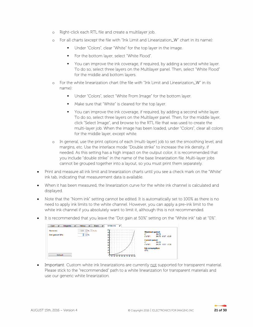
• It is recommended that you leave the “Dot gain at 50%” setting on the “White ink” tab at “0%”.
• Important: Custom white ink linearizations are currently not supported for transparent material. Please stick to the “recommended” path to a white linearization for transparent materials and use our generic white linearization.
AUGUST 15th, 2016 – Version 4 © Copyright 2016 | ELECTRONICS FOR IMAGING INC 22 of 30
Clear ink
The amount of clear ink in the full-tone can be controlled in the "Ink Limit and Linearization" step by setting a pre-ink limit.
Linearizing clear ink using Color Tools is not supported.
Creating a Media Profile
Purpose of the “Profiling” wizard
o The “Profiling” wizard guides you through the steps required to create an ICC profile for your linearization.
IT8.7/4 is the recommended profiling chart to use. Smaller charts may also produce good results, as well reducing the measurement effort, but the IT8.7/4 includes enough patches to characterize any gamut shape and is the best choice overall.
A new profiler has been introduced for EFI VUTEk, EFI Matan and EFI Reggiani in Fiery XF 6.3.
The following profiler settings are available through four tabs:
AUGUST 15th, 2016 – Version 4 © Copyright 2016 | ELECTRONICS FOR IMAGING INC 23 of 30
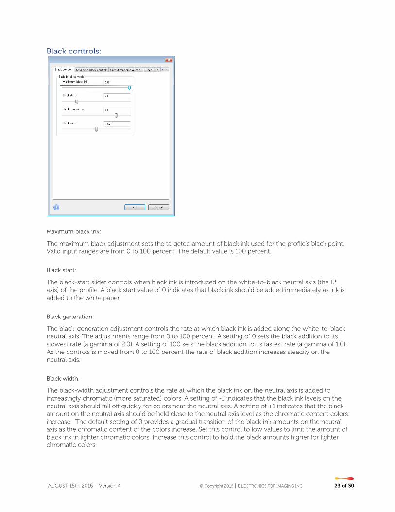
Black controls:
Maximum black ink:
The maximum black adjustment sets the targeted amount of black ink used for the profile’s black point. Valid input ranges are from 0 to 100 percent. The default value is 100 percent.
Black start:
The black-start slider controls when black ink is introduced on the white-to-black neutral axis (the L* axis) of the profile. A black start value of 0 indicates that black ink should be added immediately as ink is added to the white paper.
Black generation:
The black-generation adjustment controls the rate at which black ink is added along the white-to-black neutral axis. The adjustments range from 0 to 100 percent. A setting of 0 sets the black addition to its slowest rate (a gamma of 2.0). A setting of 100 sets the black addition to its fastest rate (a gamma of 1.0). As the controls is moved from 0 to 100 percent the rate of black addition increases steadily on the neutral axis.
Black width
The black-width adjustment controls the rate at which the black ink on the neutral axis is added to increasingly chromatic (more saturated) colors. A setting of -1 indicates that the black ink levels on the neutral axis should fall off quickly for colors near the neutral axis. A setting of +1 indicates that the black amount on the neutral axis should be held close to the neutral axis level as the chromatic content colors increase. The default setting of 0 provides a gradual transition of the black ink amounts on the neutral axis as the chromatic content of the colors increase. Set this control to low values to limit the amount of black ink in lighter chromatic colors. Increase this control to hold the black amounts higher for lighter chromatic colors.
AUGUST 15th, 2016 – Version 4 © Copyright 2016 | ELECTRONICS FOR IMAGING INC 24 of 30
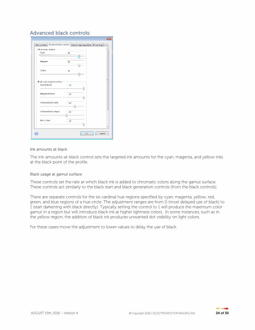
Advanced black controls:
Ink amounts at black:
The ink-amounts-at-black control sets the targeted ink amounts for the cyan, magenta, and yellow inks at the black point of the profile.
Black usage at gamut surface:
These controls set the rate at which black ink is added to chromatic colors along the gamut surface. These controls act similarly to the black start and black generation controls (from the black controls). There are separate controls for the six cardinal hue regions specified by cyan, magenta, yellow, red, green, and blue regions of a hue circle. The adjustment ranges are from 0 (most delayed use of black) to 1 (start darkening with black directly). Typically setting the control to 1 will produce the maximum color gamut in a region but will introduce black ink at higher lightness colors. In some instances, such as in the yellow region, the addition of black ink produces unwanted dot visibility on light colors. For these cases move the adjustment to lower values to delay the use of black.
AUGUST 15th, 2016 – Version 4 © Copyright 2016 | ELECTRONICS FOR IMAGING INC 25 of 30
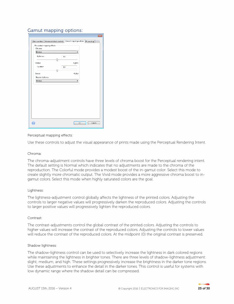
Gamut mapping options:
Perceptual mapping effects:
Use these controls to adjust the visual appearance of prints made using the Perceptual Rendering Intent.
Chroma:
The chroma-adjustment controls have three levels of chroma boost for the Perceptual rendering intent. The default setting is Normal which indicates that no adjustments are made to the chroma of the reproduction. The Colorful mode provides a modest boost of the in-gamut color. Select this mode to create slightly more chromatic output. The Vivid mode provides a more aggressive chroma boost to in-gamut colors. Select this mode when highly saturated colors are the goal.
Lightness:
The lightness-adjustment control globally affects the lightness of the printed colors. Adjusting the controls to larger negative values will progressively darken the reproduced colors. Adjusting the controls to larger positive values will progressively lighten the reproduced colors.
Contrast:
The contrast-adjustments control the global contrast of the printed colors. Adjusting the controls to higher values will increase the contrast of the reproduced colors. Adjusting the controls to lower values will reduce the contrast of the reproduced colors. At the midpoint (0) the original contrast is preserved.
Shadow lightness:
The shadow-lightness control can be used to selectively increase the lightness in dark colored regions while maintaining the lightness in brighter tones. There are three levels of shadow-lightness adjustment: slight; medium; and high. These settings progressively increase the brightness in the darker tone regions. Use these adjustments to enhance the detail in the darker tones. This control is useful for systems with low dynamic range where the shadow detail can be compressed.
AUGUST 15th, 2016 – Version 4 © Copyright 2016 | ELECTRONICS FOR IMAGING INC 26 of 30
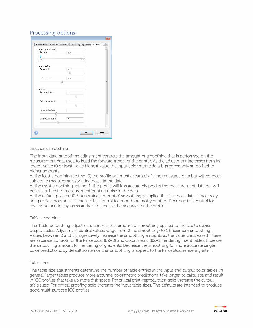
Processing options:
Input data smoothing:
The input-data-smoothing adjustment controls the amount of smoothing that is performed on the measurement data used to build the forward model of the printer. As the adjustment increases from its lowest value (0 or least) to its highest value the input colorimetric data is progressively smoothed to higher amounts. At the least smoothing setting (0) the profile will most accurately fit the measured data but will be most subject to measurement/printing noise in the data. At the most smoothing setting (1) the profile will less accurately predict the measurement data but will be least subject to measurement/printing noise in the data. At the default position (0.5) a nominal amount of smoothing is applied that balances data-fit accuracy and profile smoothness. Increase this control to smooth out noisy printers. Decrease this control for low-noise printing systems and/or to increase the accuracy of the profile.
Table smoothing:
The Table-smoothing adjustment controls that amount of smoothing applied to the Lab to device output tables. Adjustment control values range from 0 (no smoothing) to 1 (maximum smoothing). Values between 0 and 1 progressively increase the smoothing amounts as the value is increased. There are separate controls for the Perceptual (B2A0) and Colorimetric (B2A1) rendering intent tables. Increase the smoothing amount for rendering of gradients. Decrease the smoothing for more accurate single color predictions. By default some nominal smoothing is applied to the Perceptual rendering intent.
Table sizes:
The table size adjustments determine the number of table entries in the input and output color tables. In general, larger tables produce more accurate colorimetric predictions, take longer to calculate, and result in ICC profiles that take up more disk space. For critical print-reproduction tasks increase the output table sizes. For critical proofing tasks increase the input table sizes. The defaults are intended to produce good multi-purpose ICC profiles.

AUGUST 15th, 2016 – Version 4 © Copyright 2016 | ELECTRONICS FOR IMAGING INC 27 of 30
Extended gamut inks:
These selections control how the extra-gamut colorants are mixed with the C, M, and Y primaries. The selection of three-color overprints versus two-color overprints depends on the colorimetric strength of the extended gamut colorants.
• If the colorants are light and used to primarily extend the color gamut at the top of the gamut select the use of the three-color overprint.
• If the colorants are darker and high density then consider deselecting the option for that colorant.
Use Orange (or red) in three-color overprint to extend gamut: Select this option to allow full three color overprints (O+M+Y) of O, M, and Y inks. If unselected orange over prints are limited to O+M and O+Y.
Use Green in three-color overprint to extend gamut: Select this option to allow full three color overprints (G+C+Y) of G, C, and Y inks. If unselected green over prints are limited to G+C and G+Y.
Use Violet (or blue) in three-color overprint to extend gamut: Select this option to allow full three color overprints (V+M+C) of C, M, and V inks. If unselected violet over prints are limited to V+M and V+C.
AUGUST 15th, 2016 – Version 4 © Copyright 2016 | ELECTRONICS FOR IMAGING INC 28 of 30
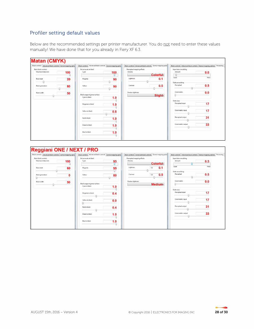
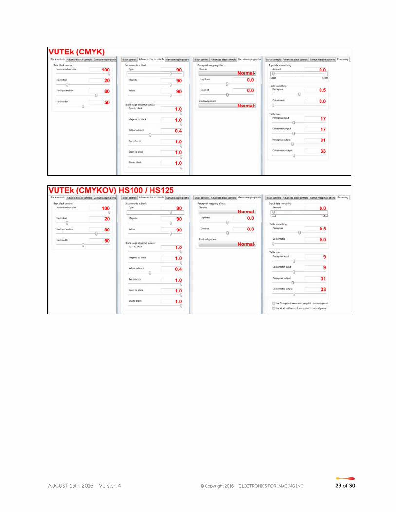
Profiler setting default values Below are the recommended settings per printer manufacturer. You do not need to enter these values manually! We have done that for you already in Fiery XF 6.3.
AUGUST 15th, 2016 – Version 4 © Copyright 2016 | ELECTRONICS FOR IMAGING INC 29 of 30

AUGUST 15th, 2016 – Version 4 © Copyright 2016 | ELECTRONICS FOR IMAGING INC 30 of 30
Hints on saving ink
The following settings will help you to achieve a specific compromise between gamut size, graininess and ink saving.
Note that ink saving is very application-dependant. Saving ink at the expense of smoothness may be perfectly fine for an outdoor advertisement viewed from a typical distance of 3-5 m, but less aggressive ink saving might be more appropriate for an indoor advertisement and a viewing distance of 50 cm.
Recommended linearization tools for ink saving:
Step Feature/setting Ink saving potential Risk Recommended for ink saving?
Ink Limit and Linearization
Lower "Norm ink" Medium Loss of gamut No
Ink Limit and Linearization
Lower "Norm ink start"
High Increased graininess
Yes
Ink Limit and Linearization
Lower "Light ink in full tone"
High Loss of gamut, increased graininess
Yes
Advanced ink limits Lower "200%, 300% and/or 400%" limits
Low Loss of gamut, inversions
No
Advanced ink limits Increase "Light ink reduction"
Low Graininess, inversions
No
Advanced ink limits Increase “Light ink reduction in overprints”
Low Inversions No
Recommended profiling settings for ink saving:
Step Feature/setting Ink saving potential Risk Recommended for ink saving
Black Controls Lower "Black start" Medium Graininess Yes
Black Controls Increase "Black Generation"
High Graininess Yes
Compatibility Note that Fiery XF 6.3 EPLs cannot be used in Fiery XF 6.2 or earlier versions!