plasma thrusters for low flying satellites:...
TRANSCRIPT
IEPC-93-017 192
PLASMA THRUSTERS FOR LOW FLYING SATELLITES:
A SPACE TELEPHONE SYSTEM APPLICATION
G.A. Dahlen*, P.J. Baum**, D.Y. Chengt
Abstract A Review of Current Systems
Commercialization of space technology will pro- GEO Systemduce the next generation of world wide telephone sys-tems. In recent years a number of space telephone con- Early spacecraft had relatively low transmitting powercepts have been proposed which vary in size from the of4to6 watts.They had extremely large ground antennaslarge Russian Komata 30 meter antenna at GEO to small and achieved their high gain by a highly focused beam.LEO systems with multiple satellites. Their merits will For a satellite at GEO (i.e., COMSAT), having an an-be decided by commercial survivability. However, all tenna to beam down a broadcast which covers the earthconcepts will need station keeping propulsion systems, has (ideally) a 17.3" beam angle. This may be comparedand may also benefit from orbit raising thrusters. with an antenna which has a * beam angle and 300 times
the gain (17.32), but only an approximate 800 kmThe weight of the satellite translates directly to coverage on the earth's surface. To achieve a narrow-
launchcosts.Solarpowered,highspecificimpulseplasma angle, high gain beam requires using large antennas.thrusters reduce on orbit propellant mass requirementsand become more attractive than the chemical propellant Cellular phones are low power, essentially omni-options for long duration missions. This paper describes directional, and at least 35,900 km from the GEO Satel-the versatility and recent breakthrough in scaling of the lite. This forces the telephone systems to a cellularCheng Deflagration Thruster for satellite propulsion concept with a number of up-link/down-link stations toapplications. communicate with the satellite. (Cellular phone repeater
stations typically have a 8 km radius for coverage.) TheIntroduction cost of the GEO system, with fewer satellites, might be
less expensive than the LEO system, but the cost to linkCommercial telephones are a trillion dollar market the overall system with all the up- and down- link stations
worldwide. A small personal telephone which allows one will be more expensive. Equally important, this limits theto can call anywhere in the world will be realized when users to the proximity of ground level communicationsa number of large companies jointly pool their technolo- rather than directly to a satellite.gies. This is similar to the race for the color televisionmarket when RCA and Columbia competed to becomethe national standard in the early 1950's. Recently, the LEO SystemsRussian agency, Komata, opened the opportunity tocommercialize their satellite, a thirty-meter antenna lo- The LEO concept essentially moves the groundcated at the GEO'. Some echo problems, etc., with their repeater system to the low flying satellites. Therefore,system were claimed to have been solved. However, the anyone who has a telephone pointed skyward can talk toproblem is not with the satellite itself, but rather how to anyone else around the world. The satellite flying at lowminimize the transceiver power of a hand-held tele- earth orbit, again will be determined by the transmittingphone. This is the mass market where telephone compa- power of the hand-held phones rather than the repeaternies controversies are generated. power of the satellite. Thus, the choice of satellite orbit
becomes controversial. In general, it will be on the orderof 400 km to 800 km above the earth's surface.
* Staff Scientist, General Research Corp., Santa Barbara, CA** President, Baum Technology, Santa Barbara, CAt CEO, Cheng Technology & Services, Sunnyvale, CA
1
193 IEPC-93-017
As an example, a VHF transceiver with a good line promising candidate for reducing launch costs and ex-of sight has a range of one watt for every 16 km. tending satellite lifetime. The extremely low plume di-(Similarly, the minimum transmitting power of a hand- vergence reduces surface contamination, minimizesheld telephone (UHF) is currently 0.3 watt for a 8 km moments from plume/satellite surface interaction, andrange, which is equivalent to 1 watt for every 14 km of offers the potential for reduced EMI.range.) Just to reach the LEO satellites, scaling thecurrent technology requires the transmitter power withan isotropic antenna to be 625 watts for the 400 km The Deflagration Plasma Thrustersatellite and 2.5 kwatt for 800 km satellite. Assuming thecurrent, higher power 3 watt phones are used, the gain The Early Cheng Deflagration Plasma Thrusterrequired would be 208 times for the 400 km satellite and833 times for the 800 km satellite. These gains may be The coaxial plasma gun was developed by Marshall 3
achievable with electronics and special antenna design. and operated at Los Alamos and other labs in the so-called "detonation" mode wherein the driving current
An additional factor is satellite constellation size. sweeps the plasma up into a thin and hot layer via theConstellation number grows at lower altitude, but orbital snowplow mechanism.insertion costs are also reduced at lower altitude.
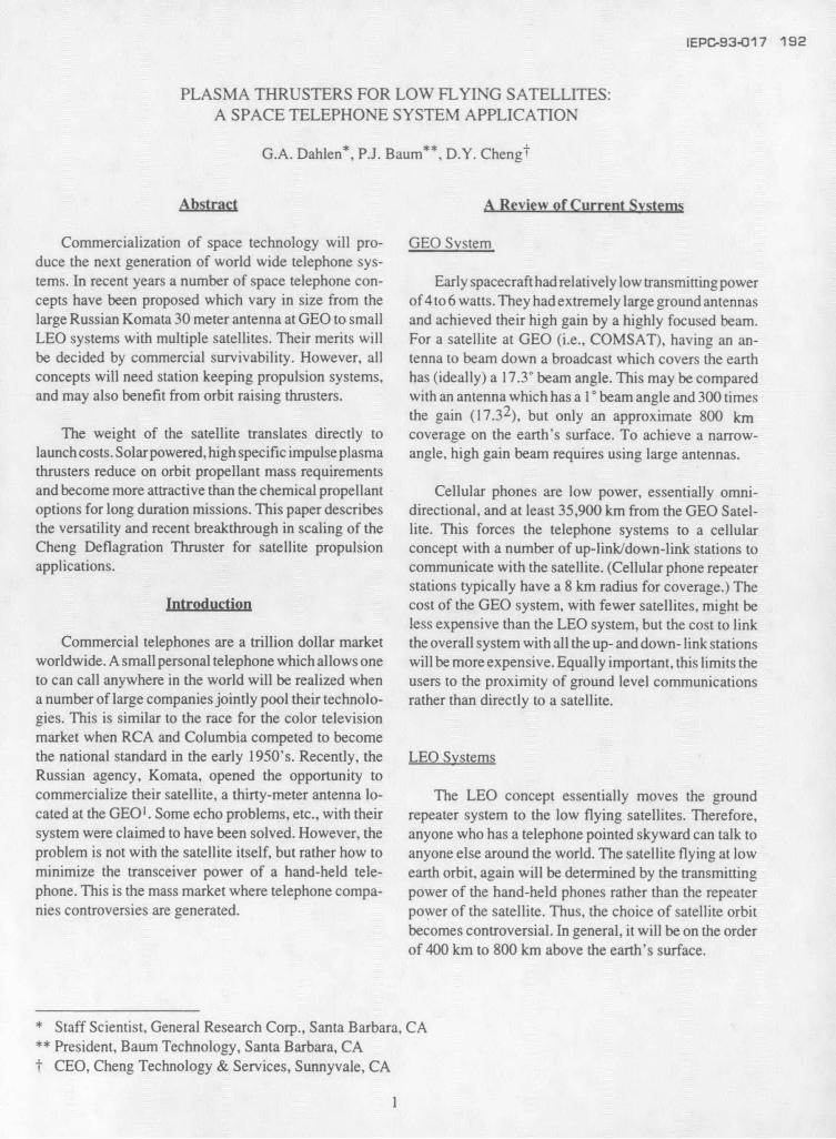
The deflagration plasma accelerator, shown in Fig-The Drag of the LEO Satellite ure 1, was invented and designed by Dr. D.Y. Cheng4.
Cheng discoveredThe choice of either an 800 km orbit or a 400 km orbit
could be a small sacrifice for the ground phone system O-Z ,,Owhich assumes the technical difficulties with transmis-sion can be overcome. The earth's atmosphere changesits density by two orders of magnitude 2 between thesealtitudes. Similarly, the drag of the satellite changes byapproximately two orders of magnitude. Should techni- ......cal issues drive a system to a lower orbit, orbital decay L
must be considered. '"
The proximity of the atmosphere induces parasitic Figure 1. The Cheng Coaxial Plasma Thrusterdrag. Without the application of a scaleable high specificimpulse (Isp) thruster system, orbital lifetime below a that by proper matching of external electrical power500 km altitude is drastically reduced 2. Similarly, solar input with propellant gas feed rate, the plasma accelera-and lunar gravitational variations also impart momentum tion could take place as a quasi-steady flow process,changes to the satellite which require thrust correction. wherein the acceleration layer was wide, the plasma
exhaust temperature cool, and the exit velocity was muchThe ideal stationkeeping thruster is small and oper- higher than in previous experiments. This expansion-
ates with a high Isp (at least 2,000 second). Thus, satellite cooling mode of acceleration was termed "deflagration"momentum corrections are made with minimum use of by Cheng to distinguish it from the compression-heatingpropellant mass. Consequently, less propellant mass is detonation mode which had been prevalent before inrequired in orbit and a system trade-off can provide either MPD arcs.extended satellite lifetime or reduced launch mass (andcost) for a given mission. The ideal thruster also has In practice, deflagration was first achieved by intro-minimal electromagnetic interference (EMI) with the ducing neutral gas into an evacuated accelerator with livecommunication system, and minimal plume induced (charged) electrodes. The absence of background gassurface contamination. avoided the formation of a snowplow by eliminating
collisions ahead of the breakdown region. During earlyThis paper presents results recently obtained from a work with NASA, the Cheng Deflagration Accelerator
Cheng Deflagration Plasma Thruster which shows high was studied with space propulsion as the primary appli-thrust density, high specific impulse (Isp) and low plume cation. In later work, at the University of Santa Clara,thedivergence. The high thrust density and Isp make it a focus changed to power production by thermonuclear
2
IEPC-93-017 194
fusion. The deflagration accelerator was also used as asolar wind simulator5.
Other laboratories 6.7 have duplicated the Cheng -Thruster to a degree. They have identified the existenceof the deflagration mode of discharge.
Cheng's Thruster was electrically powered by ca-pacitor banks and the propellant gas was introduced by a .1fast acting gas valve which was driven electromagneti- .
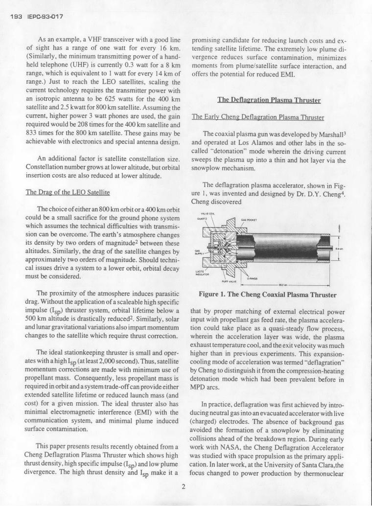
cally by a smaller capacitor bank. The larger capacitorbank (15-120 microfarads) was typically charged to 15- Figure 2. Input Parameters for a 15 Microfarad18 kV providing a pulsed power source capable of Low Voltage Thrusterdelivering up to a few hundred kiloamps peak current. Asthis current flowed across the electrodes it produced a self breakdown. This process was the focus of Cheng'sLorentz force yielding thrust. Cheng reported 4 that ve- attention which led to the switched deflagration plasmalocities up to 1000 km/s were observed and that the thrust thruster work.vector could be focused. Pendulum experiments provid-ed clear evidence of high thrust, and the efficiency of GRC Verification of the Early Cheng Thrusterenergy conversion from electrical to kinetic was esti-mated at >50%. GRC decided to verify and extend the early thruster
results at their Santa Barbara site. Subsequently, a labo-Input parameters for a coaxial thruster operated at ratory was constructed with a 3 meter long by 0.25 meter
very modest levels are shown in Figure 2 for the case of diameter (glass) test range to study the Deflagrationa thruster driven by a 60 microfarad capacitor bank 4. Plasma Thruster. Operation began at modest energyInput current, voltage, power and energy which are levels (60 microfarads, 12-18 kV, a few hundredplotted versus time on a scale of 0-8 microseconds. Initial kiloamps). The results verified Cheng's results in allbank energy was 9.7 kJ at 18 kV. The peak current was essential aspects showing very high thruster exit velocity116 kiloamps with an instantaneous peak power of 1.1 which imparted significant impulse to target pendulums,gigawatts. and well collimated plume bum patters on aluminum
witness foils. Consequently, the thruster was scaled up inThis early work was limited by power capacitor energy.
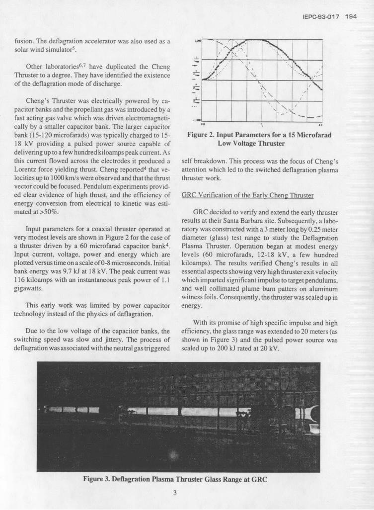
technology instead of the physics of deflagration.With its promise of high specific impulse and high
Due to the low voltage of the capacitor banks, the efficiency, the glass range was extended to 20 meters (asswitching speed was slow and jittery. The process of shown in Figure 3) and the pulsed power source wasdeflagration was associated with the neutral gas triggered scaled up to 200 kJ rated at 20 kV.
Figure 3. Deflagration Plasma Thruster Glass Range at GRC
3
195 IEPC-93-017
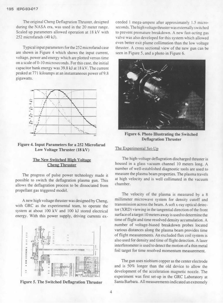
The original Cheng Deflagration Thruster, designed ceeded 1 mega-ampere after approximately 1.5 micro-during the NASA era, was used in the 20 meter range. seconds.ThehighvoltagethrusterwasextemallyswitchedScaled up parameters allowed operation at 18 kV with to prevent premature breakdown. A new fast-acting gas252 microfarads (40 kJ). valve was also developed for this system which allowed
even better exit plume collimation than the low voltageTypical input parameters for the 252 microfarad case thruster. A cross sectional view of the new gun can be
are shown in Figure 4 which shows the input current, seen in Figure 5, and a photo in Figure 6.voltage, power and energy which are plotted versus timeon a scale of 0-10 microseconds. For this case, the initial
SFigure 6. Photo Illustrating the SwitchedDeflagration Thruster
Figure 4. Input Parameters for a 252 MicrofaradLow Voltage Thruster (18 kV) The Experimental Set-Up
The New Switched High Voltage The high-voltage deflagration discharged thruster isCheng Thruster housed in a glass vacuum channel 10 meters long. A
number of well-established diagnostic tools are used to
The progress of pulse power technology made it measure the plasma beam properties. The plasma travels
possible to switch the deflagration plasma gun. This at high velocity and is well collimated in the vacuum
allows the deflagration process to be dissociated from chamber.
propellant gas triggered model.The velocity of the plasma is measured by a 8
A new high voltage thruster was designed by Cheng, millimeter microwave system for density cutoff andwith GRC as the experimental team, to operate the transmission across the beam. A soft x-ray optical detec-system at about 100 kV and 100 kJ stored electrical tor (XRD) viewing in the tangential direction of the front
energy. With this power supply, driving currents ex- surface of a target 10 meters away is used to determine thetime of flight and time resolved density accumulation. Anumber of voltage-biased breakdown probes located
Sf p various distances along the plasma beam provides timeSof flight measurements. An excluded flux coil system is
hip also used for density and time of flight detection. A laser- interferometer is used to detect the motion of a thin metal
foil target for time resolved momentum measurement.
S l ti- c The gun uses niobium copper as the center electroden and is 50% longer than the old device to allow the
J: T Hf tdevelopment of the acceleration magnetic nozzle. ThefI i experiment was first set-up in the GRC Laboratory at
Figure 5. The Switched Deflagration Thruster Santa Barbara. All measurements indicated an extremely
4

IEPC-93-017 196
fast deflagration plasma, followed by a slower snow- (Isp). but only for a short duration. This is followed by aplow, higher density plasma due to capacitor ringing, longer duration pulse with an order of magnitude lowerThe capacitor ringing was damped later by a rapid rising specific impulse. Both values of Ip are extremely high inresistance system which uses tungsten wire system en- comparison with all the other currently known systems,closed in argon atmosphere. This reduces substantially including ion thrusters, MPD arc and arc jets. From thethe amount of snowplow plasma and electrode erosion. target impact measurement, it is obvious that a majority
of the impact is provided by the slower pulse and theTest Results forces are very high. This indicates that it has a very high
thrust capability for a given Isp level. The results of aThe test results of all the measurement systems are, single pulse, using thick aluminum foils can be seen in
in general, agree with each other. The deviation of the Figure 8. Even 0.005" thick foil located 8 meters awaydifferent diagnostic system results are: (1) all the indirect were penetrated. The image coincided with the diametermeasuring systems including the microwave of the anode diameter. This suggests excellent collima-transmittance,the XRD optic detector, and the excluded tion.flux system agree with each other exactly; (2) the electricbreakdown probe is, in general, 2-3 microseconds later." "It is possible that the density requirement for the break- .down probe to work is higher, or simply that the delayedbreakdown is due to high plasma velocity effect; (3) thetarget foil measurement indicates foil acceleration at thisdelayed time. The example shown in Figure 7 illustratesthat a very fast low-density plasma traveled a distance of -
10 meters downstream of the thruster at a frontal speed of :: :over 108 cm/second and arrived about 8 microsecondsafter the initiation of the discharge. The plasma densityshould be above 1013 particles/cm 3 which is the range ofthe microwave cutoff density. Figure .8 Target Damage Experimental Results
Using the definition of the specific impulse as the Space Chamber Testsvelocity divided by gravitational constant (g) indicatesthat the plasma has a 105 second range specific impulse The tests in the long glass vacuum chamber showed
high impact energy, high velocity, space charge neutralVALVE at=5 fast beam with temperature on the order of 1/2 eV.
CURRENT
As noted below, the beam is highly collimated. Itremained to show that the plasma collimation was not
CURRENT caused by a vacuum chamber wall effect. To verify thatthe thruster beam propagates in free space, the experi-
II ment was moved to the space environmental chamber(Mark I) at Arnold Engineering Development Center
TRANSMISSION ATTENUATION (AEDC).IL -00 CUT OFF
Io FIRS OFF SCALE The Space Environmental ChamberSIGNAL (H IEMISSION ARRIVAL
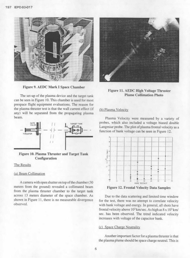
AT 10m STATION) A picture of the AEDC Mark I Space ChamberII Facility is shown in Figure 9. The space chamber has
FE --" " .. inside working dimensions of 10.4 meters in diameter byE URTURBED 19.8 meters high. There are three large entrances to the
I J chamber; one from the top, one from the bottom, and one0 50 100 150 200 250 from the side. There also exists a multitude of smaller (<
TIME55 cm) access ports at four (4) primary and eight (8)
Figure 7. Diagnostic Data Example secondary levels at the diameter of the chamber.
5
197 IEPC-93-017
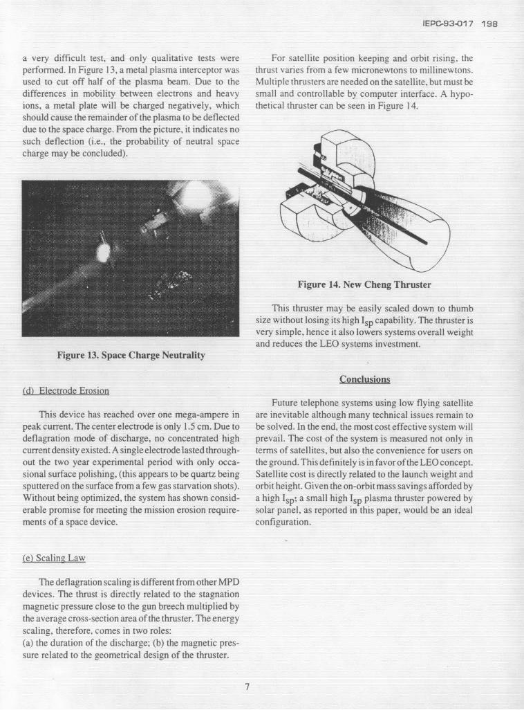
Figure 9. AEDC Mark I Space ChamberFigure 11. AEDC High Voltage Thruster
The set-up of the plasma device and the target tank Plume Collimation Photocan be seen in Figure 10. This chamber is used for mostprespace flight equipment evaluations. The reason forthe plasma thruster test is that the wall current effect (if (b) Plasma Velocityany) will be separated from the propagating plasmabeam. Plasma Velocity were measured by a variety of
GATE I TARGETTANK probes, which also included a voltage biased doubleLangmiur probe. The plot of plasma frontal velocity as a
~ i - -~ function of bank voltage can be seen in Figure 12.THRUSTER
Figure 10. Plasma Thruster and Target TankConfiguration W 2
The Results - - -
(a) Beam Collimation , -
0 1 . - -A camera with open shutter on top of the chamber (30 AN '" v Tl:rm;:
meters from the ground) revealed a collimated beam Figure 12. Frontal Velocity Data Samplesfrom the plasma thruster chamber to the target tankacross 13 meters diameter of the space chamber. As Due to the data scattering and limited time windowshown in Figure 11, there is no measurable divergence for the test, there was no attempt to correlate velocityobserved. with bank voltage and energy. In general, all shots have
frontal velocity above 103 km/sec. As high as 8 x 10³ km/sec. has been observed. The trend indicated velocityincreases with voltage of the capacitor bank.
(c) Space Charge Neutrality
Another important factor for a plasma thruster is thatthe plasma plume should be space charge neutral. This is
6
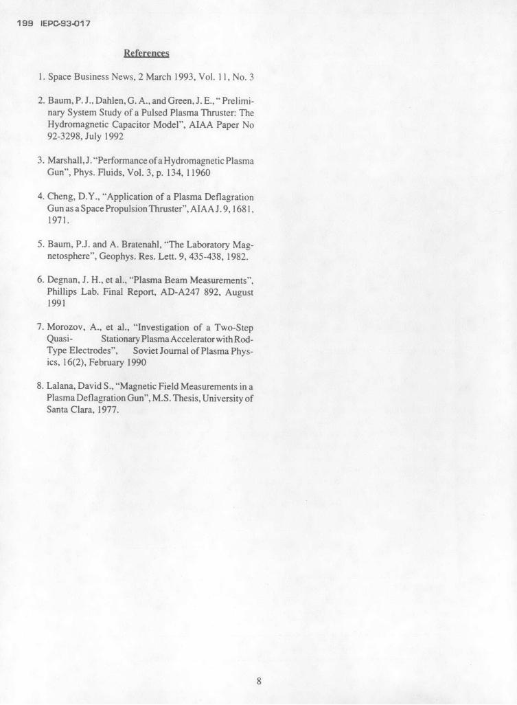
IEPC-93-017 198
a very difficult test, and only qualitative tests were For satellite position keeping and orbit rising, theperformed. In Figure 13, a metal plasma interceptor was thrust varies from a few micronewtons to millinewtons.used to cut off half of the plasma beam. Due to the Multiple thrusters are needed on the satellite, but must bedifferences in mobility between electrons and heavy small and controllable by computer interface. A hypo-ions, a metal plate will be charged negatively, which thetical thruster can be seen in Figure 14.should cause the remainder of the plasma to be deflecteddue to the space charge. From the picture, it indicates nosuch deflection (i.e., the probability of neutral spacecharge may be concluded).
Figure 14. New Cheng Thruster
This thruster may be easily scaled down to thumbsize without losing its high Isp capability. The thruster isvery simple, hence it also lowers systems overall weightand reduces the LEO systems investment.
Figure 13. Space Charge Neutrality
Conclusions(d) Electrode Erosion
Future telephone systems using low flying satelliteThis device has reached over one mega-ampere in are inevitable although many technical issues remain to
peak current. The center electrode is only 1.5 cm. Due to be solved. In the end, the most cost effective system willdeflagration mode of discharge, no concentrated high prevail. The cost of the system is measured not only incurrent density existed. A single electrode lasted through- terms of satellites, but also the convenience for users onout the two year experimental period with only occa- the ground. This definitely is in favor of the LEO concept.sional surface polishing, (this appears to be quartz being Satellite cost is directly related to the launch weight andsputtered on the surface from a few gas starvation shots). orbit height. Given the on-orbit mass savings afforded byWithout being optimized, the system has shown consid- a high Isp; a small high Isp plasma thruster powered byerable promise for meeting the mission erosion require- solar panel, as reported in this paper, would be an idealments of a space device, configuration.
(e) Scaling Law
The deflagration scaling is different from other MPDdevices. The thrust is directly related to the stagnationmagnetic pressure close to the gun breech multiplied bythe average cross-section area of the thruster. The energyscaling, therefore, comes in two roles:(a) the duration of the discharge; (b) the magnetic pres-sure related to the geometrical design of the thruster.
7
199 IEPC-93-017
References
1. Space Business News, 2 March 1993, Vol. 11, No. 3
2. Baum, P. J., Dahlen, G. A., and Green, J. E., " Prelimi-nary System Study of a Pulsed Plasma Thruster: TheHydromagnetic Capacitor Model", AIAA Paper No92-3298, July 1992
3. Marshall, J. "Performance of a Hydromagnetic PlasmaGun", Phys. Fluids, Vol. 3, p. 134, 11960
4. Cheng, D.Y., "Application of a Plasma DeflagrationGun as a Space Propulsion Thruster", AIAA J. 9, 168 1,1971.
5. Baum, P.J. and A. Bratenahl, "The Laboratory Mag-netosphere", Geophys. Res. Lett. 9, 435-438, 1982.
6. Degnan, J. H., et al., "Plasma Beam Measurements",Phillips Lab. Final Report, AD-A247 892, August1991
7. Morozov, A., et al., "Investigation of a Two-StepQuasi- Stationary Plasma Accelerator with Rod-Type Electrodes", Soviet Journal of Plasma Phys-ics, 16(2), February 1990
8. Lalana, David S., "Magnetic Field Measurements in aPlasma Deflagration Gun", M.S. Thesis, University ofSanta Clara, 1977.
8