electric propulsion projects and...
TRANSCRIPT

88-003
ELECTRIC PROPULSION PROJECTS AND
RESEARCHES IN JAPAN
Kyoichi Kuriki
Institute of Space and Astronautical ScienceYoshinodai, Sagamihara-shi 229, Japan
Yoshihiro Nakamura*
National Aerospace LaboratoryJindaiji-higashi-cho, Chofu, Tokyo 182, Japan
1. INTRODUCTION
The present paper gives an overview onelectric propulsion activities in Japanfrom both project and research orientedview points. The flight opportunities areSpace Flyer Unit (SFU) Mission 1 given foran MPD Thruster System and Engineering TestSatellite (ETS) VI given for an Ion EngineSystem. The systems in these missions lookforward to near future applications.
As for far future applications such as EPEX PAYLOAD UNITlunar ferry, Mars lander and deep spaceexplorer, various types of electricpropulsion could be candidates. It isessential in designing electric propulsion Fig.1 EPEX onboard SFU.systems for these missions to take intoaccount the feasible types of power andpropellant resources. In other words, the roughly equal to the requirement ofelectric propulsion system should be cancelling the aerodynamic drag to thecompatible with the future space spacecraft. The orbital data usinginfrastructures. From this view point the hydrazine propellant will be compared tovarious types of electric propulsion, which the terrestrical data which have beenmay look diversified, are encouraged to be qualified as system thrust power ratio.studied as potential options in the A breadboard model of the 1 kW MPDJapanese research activities, thruster system for the EPEX was fabricated
(Fig.2) and tested in 1987." "' The systemtest corresponds to eudurance assessment of2. PLASMA PROPULSION on-off cycle operation in a vaccuumenvironment on critical components of the2.1 Institute of Space and Astronautical systems such as MPD Head, Capacitor Bank,
Science (ISAS) and software for automatic control andmonitor. The most remarkable feature of2.1.1 SFU Project. A 1 kW MPD thruster this system test is adopting 18 segmented
system is under development in ISAS for discharge electrodes of MPD Head with anElectric Propulsion Experiment (EPEX) extended nozzle and 18 Pulse Formingonboard Space Flyer Unit (SFU) which will Networks separated for the segmentedbe launched in the early 1990s (Fig.1). electrodes. Such a concept was alreadyThis experiment is intended to demonstrate simulated in the laboratory test tothat a repetitively pulsed quasi-steady MPD demonstrate high thruster performances.5 )thruster is one of the flight-ready systems The system test started at the end of
order to promote extensive use of electric Hz which corresponds to 25 days continuouspropulsion system, its launch durability operation. After the 3 million firings,and the system performance of propulsive the system was totally checked out to findfunction must be verified in space at power no noticeable failures in the Capacitorlevel of kilowatt. The EPEX will aquire c ea b le failures in the Capacitorabout 1 kW electrical power which is Bank, tolerable order of electrode erosion
in the MPD Head, and the automatic controlhistory and monitored data of the system.
* Professor, Associate Fellow AIAA/ The system thrust power ratio was keptDirector JSASS during the test as 34 mN/kW. The specific
** Senior Research Officer, impulse indicated about 600 sec and severalMember AIAA/JSASS percents degradation was observed. The
26

cathode erosion rate was kept as 0.6 pg/C propellant were employed and a impulsethroughout the system test, which means coupling coefficient was measured. Amongthat the cathode longevity will exceed 100 these, a combination of T-CO 2 laser anddays continuous operation. water has a larger impulse coupling
coefficient as high as a few hundred dynessec/joule. A quasi-steady operation wassuccessfully conducted by a combination ofexcimer laser (ArF laser, 5 W, 100 PPS) anda metal medius. This generates about 50dynes for a Zinc target during 60 seconds.
2.2 Osaka University
S2.2.1 Quasi-Steady MPD Thruster. Thequasi-steady MPD thruster with axial
Smagnetic field coils connected in seriesSwith a pulse forming network, as shown in
Fig.4, has been studied to achieve highthrust performance and large durability inelectrothermal-electromagnetic hybridaccelerati on mode for near-earthmissions. The discharge plasma
Fig.2 Breadboard model of 1 kW MPD diagnostics and computational simulationthruster system, were performed; application of preferred
axial fields was found to bring about alarge amount of electrothermal thrust
2.1.2 MPD Arcjet. For the basic component because of effective heat ofunderstanding of correlations between the propellant due to JrxBz force.design guidelines of MPD thrusters and Furthermore, the developed MPD thrustertheir performances, a 2-dimensional MPD system with the axial magnetic field wasarcjet was fabricated to implement operated successfully in an average input.disturbance-free, multi-points and power of 1-kW, repetitive frequency of 1-Hzsimultaneous measurements of MPD and specifie impulse of 1040-sec.flowfields. A CCD camera with an image Excellent thrust performance, reliabilityprocessor, laser interferometer, and and endurance of the system components weremagnetic sensitive film are employed. An confirmed.optical image spectroscopically processed FIATING COILis exhibited in Fig.3 with evaluation of EECTROEelectron temperature. This sort of datum GAS PORTS EECTR0 5will contribute to 6 he analytical modelling/ 2 3of the MPD arcJet. 6
Ar, FLARED IV (CAVcOErh =1. 25Fg, J = 15 kA
2.42.1
1.2
o 0. 0.9 0.05m
S6 Fig.4 Quasi-steady MPD Thruster with0.3 applied magnetic field.
RELIABLE 0.0
2.2.2 Low-Power DC Arcjet Thruster. Theresearch on low-power DC arcjet thrusters
Fig.3 CCD image for electron temperature has been forcused on development of highmap of MPD flowfield. performance prototypes and elucidation of
suitable 8 eating and accelerationmechanisms.8 Figure 5 shows the improved
2.1.3 Laser Propulsion. The system study radiation-cooled arcjet thruster in 1-mmfor a laser propulsion system experiment throat diameter. The arcjet, whichonboard the Space Flyer Unit (SFU) has been achieved high thrust efficiencies as shownconducted. In this system, a subsatellite in Table 1, was operated continuouslyequipped with 0.5N level laser thruster is without electrode erosion after using thedeployed from SFU while a laser generator method of double pulse trigger for softis onboard SFU. Toward this system start-up. Furthermore, the electricexperiment, a basic research on laser breakdown and discharge patterns in low andthrustor has been conducted. It covers high voltage mode operations were observedfrom a continous-wave (CW) type to a using a visible two-dimensional arcjet; therepetitively-pulsed (RP) type laser propellant temperature distribution wasthrustor. As for a CW type, a research measured, resulting in an arc-coreabout a stability of hot spot supported by temperature of about 7,000 K at thelaser beam has been conducted. As for RP constrictor part for nitrogen and 1-kWtype, a various kind of laser generator and input power level.
27

INSULATOR ANODE 2.3 University of Tokyo
PROPELLANT Fundamental studies on an MPD arcjetIN have been continued for more than 15 years
at the Department of Aeronautics, TheC University of Tokyo. The present research
(work is concentrated on the improvement ofthe thruster performance of a steady-stateMPD arcjet. The experimental results
CARON\ obtained so far have shown a marked30mm _ GASKET CATHODE difference in thruster performance
depending on the propellant used1 '.Propellants such as hydrogen and helium
Fig.5 Low-power radiation-cooled arcjet give high thrust efficiencies at specificthruster, impulse levels of several thousand seconds,
though at a low thrust/power ratio. On the2.2.3 Electrodeless Electrothermal other hand, heavier propellants such asThrusters. Electrothermal thrusters argon and nitrogen provide higherutilizing electrodeless discharges, i.e., thrust/power ratios, but at very low thrustinductively coupled high-frequency and efficiencies. This difference inmicrowave resonance cavity discharges, have performance between propellants isbeen designed and tested to investigate th concluded to be largely a result offundamental operational characteristics.' differences in discharge currentFigures 6 and 7 show the used electrodeless distribution: for hydrogen the dischargethrusters. Regardless of providing larger- current was distributed downstream of thediameter throats, the thrust performances electrode region and a large electro-of these thruster were compared favorably magnetic acceleration caused by appliedwith those of conventional electrothermal fields occurred.thrusters such as resistojets and arcjets, The purpose of the present study is toas shown in Table 1. optimize an applied magnetic field and
anode so as to obtain a favorable currentPropellant In distribution for any propellant type. A 10
kW class MPD arcjet with applied magneticWater Cooled fields fabricated is shown Fig. 8'.InductionCoil Thrust measurement was performed using a
Quartz Glass Tube newly designed (low friction) thrust stand.Using argon, thrust efficiency of 23% at a
- ----- specific impulse of 1300 sec was obtainedin an input power range of 4kW. To enhance
Sthe thruster performance, axial anodePlasa Discharg segmentation was employed so as to optimize0 nm the current distribution for eff ctive
0 0-.l- electromagnetic acceleration(Fig. 9)WATER JACKET SOLENOIOAL COIL
Fig.6 Inductively coupled plasma thruster. WATERINSULATOR
WATER-MiFroVi. Inavpt INSULATORso e
Energy Absorptionhumber MICA SHEET
CATHOOE
SU uSPACER
PropeIan Lt = C T SEPARATEO ANODE
S. an W I ATRWA TER
"SOLENODAL PROPELLANTCOL
Cytinrical Resonance Cavity
Fig. 8 10 kW Steady-State MPD Thruster
Fig.7 Microwave cavity resonance plasmathruster. X
PROPELLANT -- \
Table 1. Thrust performance ofelectric NoEthrusters.
Thrasser 1PD OC Arcjet 1adesiver MIcrowaveCo.i ed l. c.e . - -a - ATHODE
lait o..r .r 1.1 I.I 3.4 1.11 WATER INSULATOR(1ssee____ WATER 17
SpcifIC le llsl .ree t«40 >H4 li0 2XS----- O 0 2 4cm ) /
I- SOLENOIDAL COILTreIa Power Imlio .al/l 11.1 1II 25l 111
------------------------ 11-1Fig. 9 Segmented-Anode MPD Thruster
28

2.4 Kyoto University which are written in Euler-type and includethe effect of nonequilibrium ionization-
An available thruster for future space recombination, were numerically solvedpropulsion was designed and tested in coupled with electromagnetic equations, bycooperation by Kyoto University and means of a time dependent method. TheMitsubishi Electric Corporation. Figure 10 computations use explicit TVD-MacCormackillustrates a low power DC arcjet thruster scheme and the steady state solutions werewith a radiation cooling system. This obtained as asymptotic solutions for largethruster is intended to be used for the time. The results will be presented inNorth-South station keeping of a 1-ton this conference.class spacecraft which has a lifetime often years. The thruster performance wasinvestigated by both experiments and 2.5 Ishikawajima-Harima Heavy Industriescomputations. Co. Ltd.
SIshikawajima-Harima Heavy IndustriesA 8 C 0 E Co., Ltd. (IHI) has been developing 1 kW-
class MPD arcjet system for EPEX mission ofSFU under contract with ISAS since 1986,
Gas> 3athod and takes charge of developing MPD arcjetSthruster and propellant supply system.S-Hydrazine will be used as the propellant,
which is the most popular one for reactionBoron-nitride control system of satellite. The hydrazine
is decomposed through a gas generator andfed to the MPD thruster.
0 3cm In 1987 FY, the BBMs of MPD thrusterand propellant supply system was developed.
. n- h sh The thruster BBM, as shown in Fig.12,Fig.10 Kyoto University-Mithsubi s h i includes-a segmented anode to enhance the
Electric Corporation low power thrust performance and was operatedDC arcjet thruster successively for more than 600 hours in the
endurance test of EPEX system. ) TheThe experiments were conducted in a vacuum thermal data and the thrust performance (3chamber (test chamber) which has 2,700 millions shots) in the system were alsoliters in volume. The conditions in measured in the system test. In 1988 FY,operation were the EMs of MPD thruster and propellant
propellant gas: argon supply system have been designed bytest chamber pressure: 8.9Pa reflecting the results obtained in the BBMmass flow rate: 0.11 - 0.44g/s test.arc current: 80 - 120 amps Besides developing,the flight system,arc voltage: 20 - 26 volts a basic study for improving the thrust
Thrust was measured by a load cell. Figure performance of MPD thruster has been11 shows the measured thrust vs mass flow conducted by investigating an effect ofrate. projected a1ode on the thrust
performance. The basic study has"I I I I I obtained some prospects in the reduction of
erosion characteristics and the enhancement1 of thrust performance.
oa A DC arcjet has been also studied in0s- l - collaboration with Osaka University and
a120 ISAS. The research of DC arcjet at IHI is0 -
/extended to a development of atomic oxygen/ source besides thruster. 1
,/ /0/
0.4 7
U2-
0 I I I
MASS FLOW RATE. g/sec
Fig.11 Thrust vs mass flow rate.
Fundamental studies of the flow fieldinside the thruster are needed in order todevelop the thruster. Such studies were Fig.12 MPD Thruster BBM.
conducted by numerical simulation using thesame thruster geometry as used in theexperiments. Propellant flow eqations,
29

2.6 Mitsubishi Electric Corporation Research activities for the low powerDC arcjet are also being conducted at
Mitsubishi Electric Corporation MELCO, supporting the Kyoto University.(MELCO) has been concerned with the Variation of discharge characteristics duedevelopment activities for the MPD arcjet to the nozzle geometry is being analyzed bypropulsion system jointly with the numerical calculations including ionizationInstitute of Space and Astronautical and by experimental approaches.Science (ISAS) and with Ishikawajima-harimaHeavy Industries (IHI). In SEPAC program,an MPD arcjet system integrated by MELCOwas successfully operated in spac ,although it did not aim at propulsion 5 . 3. ION PROPULSIONSince then, MELCO has been conducting theefforts to develop the power conditioning 3.1 National Space Development Agencysystem and the control system for the MPD (NASDA)propulsion system.
The Electric Propulsion Experiment 3.1.1 Activities on Ion Propusion. The(EPEX) program was planned by ISAS and is National Space Development Agency of Japanexpected to provide us with the first (NASDA), in cooperation with Nationalopportunity for space test of the 1kW class Aerospace Laboratory (NAL) andMPD propulsion system. The bread board Electrotechnical Laboratory (ETL),model (BBM) test for EPEX was carried out conducted the space experiment of 2 mNfrom Dec. 1987 to Feb. 1988. class mercury ion engine systems on ETS-
Plastic film capacitors have been III, which was flown in 1982. Theadopted for the pulse forming networks operations of the ion engine systems were(PFNs) which are the main components in the successfully performed in space. Thepower conditioning systems, since the experiments continued to achieve about 420plastic film capacitors have much superior hours of ion thruster operation includingendurance for repetitive cycles of charging 270 hours of ion acceleration withoutand discharging to th~ others such as failures to March, 1985 when the satellite,electrolytic capacitorsl 6 . In order to ETS-III, stopped functioning with depletionfacilitate adoption of the newly) developed of the hydrazi ) used in its reactionsegmented anode discharge head , the PFN control system. NASDA evaluated thewas divided in 18 channels. Each of the performance of the ion engine system andchannels provides one segment of the anode its operating condition on the satellite.with almost equally divided amount of the On the other hand, NASDA is carrying outdischarge current. The characteristics of the development of the Engineering Testthe PFN tested is summarized in Table 2. Satellite VI (ETS-VI), a two ton weight andThe total number of firings on the test ten years life satellite to be launched inamounted to 3 millions. The power 1992, in order to acquire satellite busconversion efficiency in the PFN was 84% or technologies useful in 1990's. In thisgreater. The required performance and development, the ion propulsion is thoughtendurance of the PFN were verified by the to be utilized for station keeping, becauseBBM test. In addition to the conventional of much reduction of required propellantsequence controller for the repetitive weight. Based on the trade-off results forfirings, a micro-computer based control and the ETS-VI as well as the success in themonitor system was employed on the BBM test space experiment on the ETS-III, NASDAto simulate the function of control for the chose the xenon ion engine system (IES) forflight system, since an automated control north south station keeping of the ETS-VI.of the experiment execusion and monitoringis required for the EPEX. Although thesystem was composed of generic ground use 3.1.2 Development of ETS-VI Ion Enginehardware, the control sequence and System. Research and development works onargorithm were verified in the course of the ion engine system had been carried out
. from 1983 through 1985, 1 and the keythe BBM test. The design considerations parameters were specified for the ETS-VI.for the engineerngg models for EPEX are The formal development of the ETS-VI IES,conducting now based on the BBM test on which the schedule is shown in Fig.13,results. started in 1986. Preliminary experiments
Table2.Characteristics of the PFN (EPEX on the performance, durability, EMI and
BBM). interface between the subsystems, andstructural and thermal analyses had beenconducted for the IES. The preliminarydesign review for it has been over this
Total Capacitance 10160 spring. The ion engine system is composedof four Kaufman xenon ion thrusters (TRS),
Total Inductance 12 pH four power processor units (PPU), athruster control unit (TCU) and propellant
Chging Vol 3V management unit (PMU). NASDA performs theChaging Volage 340V development program with the support of NAL
in contract with Mitsubishi ElectricStoredEnergy 574 J corporation (MELCO) on the system design,
integration and the development of the TRSSize 1058X 750 X 200 mm and PMU, and with Toshiba on the
development of the PPU and TCU. Figures 14Characterisic Impedance 34 mOhm through 16 show the Development Modules of
the TRS, PPU and TCU respectively. ThePulse Duration 700 psec total mass of the IES is estimated to be
131 kg including 40 kg propellant. A pairRepetition Frequency 1.4 Hz of ion thrusters are mounted on the east
30

panel of the satellite and also anotherpair on the west as shown in Fig. 17. Thentwo thrusters on the opposite panelsoperate at the same time to make asynthetic thrust in the southern direction.The power processor units are located onthe north and south panels, which arethermal disposition panels.
Following the preliminary designreview, the IES design is continued indetails to satisfy the requirement of theETS-VI. Now much efforts are concentratedon the reliability, mission life anddetailed designing. After the constructionof a vacuum test facility in 1989, theexperimental evaluation of the ion thrusterlife will be conducted.
Fig.16 DM hareware of thruster control. unit.
* 2thnfI:,1, Mt ,I lmect i C aION THRUSTERS
I t )l.a (n Ic rimon (e
Fig.13 Development schedule of the ETS-VIion engine system.
Fig.17 Engineering Test Satellite-VI.
3.2 Mitsubishi Electric Corporation(MELCO)
3.2.1 Status of The Development of ETS-VIIES. Mitsubishi Electric Corporation(MELCO) has been carrying on thedevelopment of Ion Engine System (IES) forETS-VI under the contract with NASDA.
Subsystem Development Tests (DVT)using the following development models were
Fig.14 DM ion thruster, successfully performed from December 1987to February 1988.
Thruster (TRS)Power Processing Unit (PPU)
Mass Flow Controller (MFC)
Overall performance data are listed inTable 3. Data showed that overallperformance satisfied to the requirementsof ETS-VI. DVT included EMI measurementsof PPU paired with TRS. Although highernoise level of radiated emission wasobserved in the frequency range from 1MHzto 200MHz, ETS-VI approved the deviation ofexisting data from the result of EMCanalysis.
3.2.2 Contamination Evaluation and PlumeMeasurements. Contamination caused bysputtered materials of grid system is one
Fig.15 DM hardware of power processor of the significant problems for the
unit. application of the ion engine system to thesatellite. From the results of the
31

preliminary life tests, the erosion rate of The thrust correction factors by beamgrid (accelerator grid) is estimated to be divergence angle and doubly charged ionsapproximately 1x10- g/Hr. North-south are to be evaluated and the thruststation keeping of ETS-VI is performed by measurement is to be conducted.the dual operation of two thrusters, eachof which is to be operated for about 6,000hours during 10 year mission period. 3.2.3 Life Testings. Presently the
The contamination evaluation test was following life testings are going on andconducted by the support of NAL. Solar their status at July 1988 are listed below:cells (Si; 2x2cm), aluminized Kaptons,optical solar reflectors and gold plated - TRS DM(1) Life Test : 7,800hrsaluminum plates were used as thecontamination test samples and the V-I - Hollow Cathode DM(1) Life Testcharacteristics of the solar cell, andthermal characteristics of other samples Main Hollow Cathode DM(1) :were evaluated. 2,600cycles, 5,100hrs
From the configuration of ETS-VI, thecontamination of the solar cells is the Neutralizer Hollow Cathode DM (1) :most significant problem. However, the 2,600cycles, 5,100hrsresults of the V-I characteristics of thesolar cell, which has equivalent amount of - TRS DM(2) #1 Life Test : 700hrscontaminants to the actual solar cell onthe solar paddle, showed no degradation. - TRS DM(2) #2 Life Test : 1,400hrs
The ion beam divergence and thedoubly-charged ion fraction were also - Hollow Cathode DM(2) Life Testevaluated with NAL. Fig. 18. shows resultof the ion beam divergence measurement at Main Hollow Cathode DM(2) :nominal operating point (25mN). These data 1.100cycles, 2,360hrsshow that the ion beam divergence angle(95% fraction ion beam) is approximately 7 Neutralizer Hollow Cathode DM(2) :at the plane of 30cm from the grid surface. just started
The ratio of doubly to singly charged 1,100cycles, 2,360hrsions was measured in the exhaust ion beamusing a collimating ExB momentum analyzer The examinations, and data of theprobe. The probe technique provides radial erosion and the material contaminant of TRSdistribution of ion current for both DM(1) provided insight into thruster lifespecies. The average ratio of the doubly time. TRS DM(2) #1, #2 and hollow cathodecharged ions to the singly charged ions DM(2) life tests are also being carried on(I++/I+) in the ion beam is estimated to be in order to qualify a 9,500hrs life time.approximately 10%.
\3.3 Toshiba
Trs 3.3.1 Development of PPU and TCU of ETS-VIS IES. Since 1983, Toshiba Corporation has
// / been developing a power processor systemz 2.x -/ for a 20mN class ion thruster, which is
z_ ; adapted to an orbit control of ETS-VI,z 30. M6 90w i-2- under the contract with NASDA.
I ' Z9 zi2o The power processor system consists ofS6.r 9.r 9.0 a.6 a power processor unit(PPU) and a thruster
control unit(TCU).
Fig.18 Beam Divergence Angle, 9,(including 95% ion beam) at NominalOperating Point (25mN) of the ETS-VI ion thruster.
Table 3. Overall Performance of XIES(TRS/PPU/TCU/MFC)
'Pa.ra Letr Performance
Thrust(.N) 25.4 25.3 JO.2 30.1 23.2 23.3 20.2 20.2
l'ro,'>p llant r:' icLency(%) 30.6 30.4 80.6 80.4 d0.9 L.1 70.6 70.5
:on Production Cunst(v/1on) 253.9 258.2 211.0 241.8 271.7 270.5 2G6.6 237.3
SpecifLc Ilpulsc(scc) 3156.0 3148.2 3229.2 3221.2 3172.5 3180.3 2768.5 2764.7
TIS :'ower Coinsu.ption(W! 624.4 621.7 741.5 740.5 578.3 579.5 412.0 49.1.0
TIS Power ErrfclCncy(%) 77.9 78.0 78.9 79.9 77.1 77.2 73.3 70.5
Tht-ir ter Ov0eral fl'rr icncy() 62.8 52.7 54. 4 4.2 52.4 62.6 55.7 55.3
P " :niput Power(W) 723.5 720.3 339.6 j3G.3 65.2 67C.2 56 .9 56 .7
Pi'UJ Prow r f'.:':c ::cy(V ) 36.3 6.2 La.3 85.7 35.6 65.5 37.1 n6.9
Note: The calcI ulton or Thrust and Specific impulse is not corrected by couDly-cnarged Ionsand itoi on i- llv ergence.
32

The power processor unit contains the levels of the PPU and telemetry data. Thefollowing eight power supply units for the block diagram is shown in Fig.20.thruster operation as shown in Fig. 19. The DM hardwares of PPU and TCU were
PS1 : Beam grid power evaluated on their, performance in electricPS2 : Accelerator grid power performance, environment and EMC tests.PS3 : Discharge power They were tested on the interface with thePS4 : Main hollow cathode heater power DM ion thruster sucessfully in May 1988.PS5 : Main hollow cathode keeper power As for the EM hardwares, the designPS6 : Neutralizer hollow cathode has been finished and the fabrication is
heater power under way.PS7 :Neutralizer hollow cathode
keeper powerPS8 : Xenon flow controllerThe high voltage outputs for the beam 3.3.2 Research on Primary Xenon Ion
and accelerator grid powers are generated Thrusters. The research and developmentby means of a switching regulator which of a xenon ion thruster has been started inconsists of a boost chopper regulator, a cooperatin with NAL (National Aerospacecurrent resonant inverter and a voltage Laboratory) in 1985 for the purpose ofmultiplying rectifier. The power supply utilizing it for the auxilialy propulsionunits achieve the power efficiency 85%. of large space platform and the primary
propulsion of Orbit Transfer Vehicle. As aurs FUEI Iwoov.o.48 first step, a 13 cm diameter (20 mN thrust
C -TO . level) ion thruster was designed and testedS"'' in 1986. The representative performance of
inrr FILTEI -- DIaSAs cuA the thruster was an ion production cost of240 ev/ion at a propellant utilization
,4 A).u(V) efficiency of 90%. Based on the techniqueS T TE of design and production of the 13 cm ion
sOETAL thruster, a 30 cm diameter (150 mN thrustsum'I -- -= o ;sj ' .nto.A level) ion thruster has been investigated--- a-- -- A E from 1987. Fig. 21 shows the first
-n 2« MAI.(1.)i laboratory model of 30 cm diameter ionc -A.=4 thruster. The ring cusp magnetic field is
TELE T , MOITO aTPT formed by five ring shaped Sm-Co magnets
OMXrsO , c-5 "S' GCA O.I installed in upstream and side walls of the- --- I discharge chamber. The ion extraction
- ,s n, s,. s system consists of two grids of dishedFEREI.cE UA -- nISVU.Ss type. The first experimental results of
SFEN -- the thruster showed the performance of anion production cost of 175 ev/ion at apropellant utilization efficiency of 87%
Fig.19 Block diagram of Power Processor The 30 cm diameter ion thruster is beingUnit (PPU) improved to obtain the target performance,
which is a ion production cost of less thanThe thruster control unit 150 ev/ion at a propellant utilization
simultaneously operates two power processor efficiency of 90%.units corresponding to two thrusters and isinitiated by the start ground command. The THER UCSETCU controls the eight power supply unitsof the PPU in accordance with a sequentiallogic flow as monitoring the current statusof the main hollow cathode keeper, the maindischarge and the neutralizer hollowcathode keeper. The TCU has an internal PERMENredundancy and uses 8-bits micro processor MGNETas the CPU to control the sequential flowand to process commands to set output wCLLcaTH
ASSEMBLY
BUS PO1ER}BusOW -- OC/C - OC POWER B AFL
VALVECFi20M COk ANOg FUNCT r r r r DRIVEof 3m XDETECTION
RIU Uni CIRC(TIT (1 (h) IE(1)(2)
3ED ASSEBLYACCELERATOR
MONITOR DET IEGITL ECTROOE
PPU(1.44) CPU WIT ON/OFF
(1=() PPU(
1N4) DISCHARGE
ROM/RANER
TELEMETRY AMAOGINPUT UNIT PPU
PPU(11(4) MG IN TERFACEUNIT RtERECE
(N1 4) PPu(lIN4)
Fig.20 Block diagram of Thruster Control Fig.21 Schematic drawing of 30cm Xenon ionUnit (TCU) thruster.
33

3.4 National Aerospace Laboratory original and improved thrusters.With the same thruster, plasma
Research activities on xenon ion properties were measured in the dischargethrusters for auxiliary propulsion have chamber to reveal how to optimize it.been continued. Main efforts are directed Optimization would give it betterto (1) improving the performance of ion performance.thrusters with cusped magnetic fields, inhopes of their applications to north-southstationkeeping of future geostationarysatellites, (2) developing a vacuumfacility for testing ion thrusters which issuitable for xenon propellant, and (3)supporting ETS-VI ion engine development inspacecraft contamination problems, as a ---cooperative work with National SpaceDevelopment Agency.
Preliminary research on a larger xenon HOLLOW CAHODEthruster has started, in cooperation withToshiba, for future main propulsionmissions. The thruster design and test . _____results were described in the former .E .I SCREEN GRID csection. ACCELERATOR GRID
DECEL GRID
ANODE
3.4.1 Ring Cusp Ion Thruster. A 12 cm ISOLATORdiameter cusp xenon ion thruster was MAGNETSinvestigated to examine the effects of DISTRIBUTORdischarge chamber co iq aations on the---thruster performance. V The chamberhas an iron anode of 10 cm in length and ofa regular dodecagonal cross sectioncircumscribed with a 13 cm diameter circle. I to aVarious configurations of the dischargechamber were brought about by changes in SHIELDING CASEthe ring magnets, areas of the wall atcathode potential and beam diameters at the Fig.23 Thruster cross section.screen grid.
The magnet arrangement giving the bestperformance was found experimentally, andalso test results indicated that thecathode potential area has very small 40- *effects on the thruster performance and 4
that grid holes should be placed so that othe grid could extract as many coming ions * IGINALas possible.
Preliminary performance test of >another 12 cm diameter xenon ion thruster 35with improved design were performed. Fig. o o I22 shows a photograph of the thruster. This o oIMPROVEDthruster is characterized by the enlarged u o0discharge chamber diameter, the three grid A AA A Aion accerelation system and the main hollowcathode without baffle, as shown in Fig. ii 23. Test results showed that it has almost . 85 . 9 .95 1.
the same performance as the original onewith lower discharge voltage. Figure 24 PROPELLANT UTILIZATION EFFICIENCY
shows the performance comparison of the
300
U
o a D250 a
0 O IMPROVED
* ORIGINAL
85 . . 95 1.
PROPELLANT UTILIZATION EFFICIENCY
Fig.22 Photograph of Ring Cusp Ion Fig.24 Thruster PerformanceThruster.
34
3.4.2 Test Facility Development. Long spacecraft contamination. Opticalduration tests in ground facilities characteristics of other samples are being
producing a high and clean vacuum are measured.essential in developing ion thrusters, and Measurements of doubly ionized xenon
lower operating costs are preferable. Such in the thruster beam were made, of which
facilities have not been made in which abundance would degrade thruster endurance.
xenon ion thrusters can operate, although Ion beam divergence was also measured to
ones for mercury thrusters are available. insure the thruster cant angle design.The newly developed test facility,
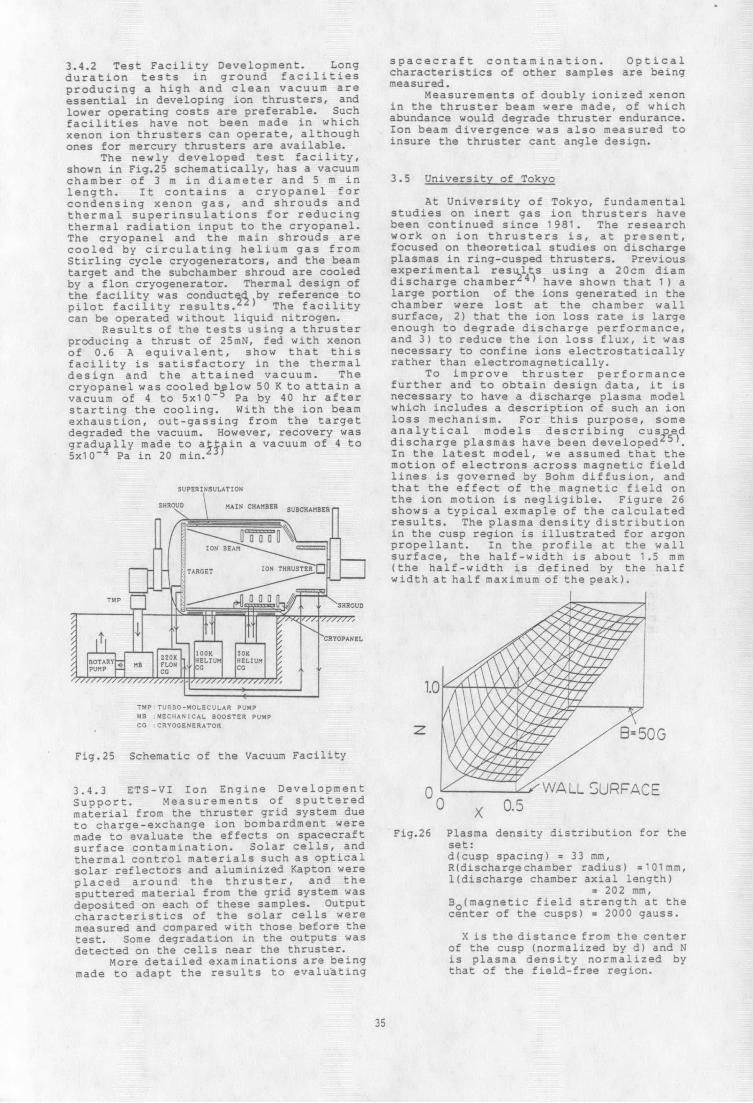
shown in Fig.25 schematically, has a vacuumchamber of 3 m in diameter and 5 m in 3.5 University of Tokyolength. It contains a cryopanel forcondensing xenon gas, and shrouds and At University of Tokyo, fundamentalthermal superinsulations for reducing studies on inert gas ion thrusters havethermal radiation input to the cryopanel. been continued since 1981. The researchThe cryopanel and the main shrouds are work on ion thrusters is, at present,cooled by circulating helium gas from focused on theoretical studies on dischargeStirling cycle cryogenerators, and the beam plasmas in ring-cusped thrusters. Previoustarget and the subchamber shroud are cooled experimental res ults using a 20cm diamby a flon cryogenerator. Thermal design of discharge chamber 2 have shown that 1) athe facility was conductd by reference to large portion of the ions generated in thepilot facility results.1 ) The facility chamber were lost at the chamber wallcan be operated without liquid nitrogen, surface, 2) that the ion loss rate is large
Results of the tests using a thruster enough to degrade discharge performance,producing a thrust of 25mN, fed with xenon and 3) to reduce the ion loss flux, it wasof 0.6 A equivalent, show that this necessary to confine ions electrostaticallyfacility is satisfactory in the thermal rather than electromagnetically.design and the attained vacuum. The To improve thruster performancecryopanel was cooled below 50 K to attain a further and to obtain design data, it isvacuum of 4 to 5x10 Pa by 40 hr after necessary to have a discharge plasma modelstarting the cooling. With the ion beam which includes a description of such an ionexhaustion, out-gassing from the target loss mechanism. For this purpose, somedegraded the vacuum. However, recovery was analytical models describing cus5e)dgradully made to apin a vacuum of 4 to discharge plasmas have been developed5x10 - Pa in 20 min. In the latest model, we assumed that the
motion of electrons across magnetic fieldlines is governed by Bohm diffusion, and
SUPERINSULATION that the effect of the magnetic field on\ the ion motion is negligible. Figure 26
SHROD MAIN CHAMBER SUSCHAMBER shows a typical exmaple of the calculated
_ results. The plasma density distribution" ~ fin the cusp region is illustrated for argon
rIN BEA propellant. In the profile at the wallsurface, the half-width is about 1.5 mm
TARGET 1ON THRUSTERO (the half-width is defined by the halfwidth at half maximum of the peak).
MP B CiAN[CAL BOOSTER PUMP
RY CRYOGENERAOPANELOR
K 50KTARYO HELIUM LHEIUM
/ I , 1.0
TMPTURBO-MOLECULAR PUMP
MB :MECHANCAL BOOSTER PUMP
z 13= 50 GFig.25 Schematic of the Vacuum Facility
3.4.3 ETS-VI Ion Engine Development 0 1 WALL SURFACESupport. Measurements of sputtered 0 0.5material from the thruster grid system due Xto charge-exchange ion bombardment weremade to evaluate the effects on spacecraft Fig.26 Plasma density distribution for thesurface contamination. Solar cells, and set:thermal control materials such as optical d(cusp spacing) = 33 mm,solar reflectors and aluminized Kapton were R(dischargechamber radius) =101mm,placed around the thruster, and the l(discharge chamber axial length)sputtered material from the grid system was = 202 mm,deposited on each of these samples. Output Bo(magnetic field strength at thecharacteristics of the solar cells were center of the cusps) = 2000 gauss.measured and compared with those before thetest. Some degradation in the outputs was X is the distance from the centerdetected on the cells near the thruster. of the cusp (normalized by d) and N
More detailed examinations are being is plasma density normalized bymade to adapt the results to evaluating that of the field-free region.
35

References
1. Y. Shimizu, K. Toki, and K. Kuriki, 12. A. E. Solem and Y. Arakawa, "Positive"Development of an MPD Propulsion Control of Current Distribution in aSystem," IEPC 88-015, 1988. Segmented-Anode MPD Thruster," Proc. of
2. H.Suzuki, K. Uematsu, T. Ohtsuka and 16th International Symposium on SpaceK. Shiina, K. Toki, and Y. Shimizu, "3 Technology and Science, Sapporo, May,Million-Shots Endurance Test of 1kw- 1988.
Class Arcjet Thruster", IEPC 88-014, 13. Ohtzuka T., Uematsu K. and Kuriki K.,1988. "Investigations on MPD arcjet with
3. Y. Kunii, M. Sumida, T. Moriai, H. Projected Anodes," IEPC 88-110, 1988.Sasaki, T. Okamura, H. Harada, and K. 14. Ishii T., Ito m., Toki K. and KurikiIjichi, Y. Shimizu and K. Toki, K., "Atomic Oxygen Flow Facility Using"Verification of Performance and Arcjet," 19th ISTS, 1988.Endurance of Capacitor Bank for the 15. K. Kuriki, et. al., "MPD Arcjet SystemElectric Propulsion Experiment (EPEX)", for space Experiment with ParticleIEPC 88-048, 1988. Accelerators (SEPAC)", AIAA-79-2072,
4. Y. Kunii, M. Sumida, T. Moriai, T. 1979.Okamura, T. Yoshida, and K. Ijichi, Y. 16. H. Harada, et. al., "Pulse FormingShimizu, and K. Toki, "Verification of Network for MPD Propulsion System withControl Sequence and Algorithm for the Improved Capacitors", AIAA-85-2059,Electric Propulsion Experiment (EPEX)", 1985.
IEPC 88-049. 17. K. Uematsu, et. al., "Development of5. E. Nishida, Y. Shimizu, and K. Kuriki, 1kW MPD Thruster", AIAA-87-1023, 1987.
"Improved Thrust Generation Mechanism 18. Kitamura, S. etal., "ETS-III Ion Enginefor Electrothermal/Electromagnetic Flight Operations in the ExtendedArcjet", IEPC88-026, 1988 Mission Period", J. Propulsion and
6. T. Nakayama, K. Toki, and K. Power, Vol.2, No.6. (1986)Kuriki,"Quantitative Imaging of MPD 19. Nakamura, Y. and Kuriki, K., "ElectricFlowfields", IEPC88-088, 1988. Propulsion Works in Japan", IAF-86-171
7. Tahara, H., Kagaya, Y. and Yoshikawa, (1986)T., "Hybrid MPD Thruster with Axial and 20. Hayakawa, Y., et.al., "The ExperimentalCusp Magnetic Fields," IEPC 88-058, Investigation on 12 cm Ring Cusp Ion1988. Thruster," Proc. of 15th ISTS, pp.97-
8. Yoshikawa,T., Onoe, K., Yoshida, H., 102, Tokyo, 1986.Kotani, S. and Suzuki, H., "Operating 21. Nakamura, Y., et.al., "DischargeCharacteristics of 1 kW Hydrazine Performance of a 12 cm Cusp Xenon IonArcjet Thruster," IEPC 88-108, 1988. Thruster, " IEPC 88-061, 1988.
9. Tahara, H., Tanaka, Y., Onoe, K. and 22. Hayakawa, Y., et. al., "A CryopumpingYoshikawa, T., "Electrothermal System for Tests of Xenon Ion Thrusters,"thrusters 'Utilizing Electrodeless Dis- AIAA Paper 87-1009, 1987.charges," IEPC 88-103, 1988. 23. Kitamiura, S., etal., "Vacuum Facility
10. Y. Arakawa and A. Sasoh, "Steady-State for Xenon Ion Thruster Testing," Proc.Permanent Magnet MPD Thruster," AIAA of 16th ISTS, Sapporo, 1988.87-1021. May 1987. 24. Arakawa, Y. and Hamatani, C., "Reduction
11. A. Sasoh and Y. Arakawa, "Optimization of Plasma Loss to Discharge Chamberof Applied Magnetic Field in a Steady- Walls in a Ring-Cusp Ion Thruster",State MPD Thruster," Proc. of 16th Propulsion and Power, Vol.3, 1987, pp.International Symposium on Space 90-91.
Technology and Science, Sapporo, May 25. Arakawa, Y. and Hamatani, C., "Analysis1988. of Plasma Loss in a Ring-Cusp Ion
Thruster", AIAA Paper 87-1079.
36