research and development of osaka institute of...
TRANSCRIPT

The 33st International Electric Propulsion Conference, The George Washington University, USA
October 6 – 10, 2013
1
Research and Development of Osaka Institute of Technology
PROITERES Nano-Satellite Series
with Electric Rocket Engines
IEPC-2013-103
Presented at the 33rd International Electric Propulsion Conference,
The George Washington University • Washington, D.C. • USA
October 6 – 10, 2013
Rikio Muraoka1, Shuya Kisaki
2, Chen Huanjun
3, Masato Tanaka
4, Hirokazu Tahara
5
Osaka Institute of Technology
5-16-1, Omiya, Asahi-Ku, Osaka 535-8585, Japan
and
Takashi Wakizono6
High Serve
780-7, Tomehara, Akiruno, Tokyo 190-0152, Japan
Abstract: The Project of Osaka Institute of Technology Electric-Rocket-Engine
onboard Small Space Ship (PROITERES) was started at Osaka Institute of Technology
(OIT) in 2007. In PROITERES, a nano-satellite with electrothermal pulsed plasma thrusters
(PPTs) was successfully launched by Indian PSLV C-21 launcher on September 9th, 2012.
The main mission is powered flight of a nano-satellite by an electric thruster. The PPT
performance in the 1st PROITERES satellite is confirmed to reach 5.0 Ns with no miss-
firing by the ground experiments. Just now, the 1st PROITERES satellite is under
operation; that is, the special FM command of PPT firing is transmitted to the satellite from
the ground station at OIT. Furthermore, the project of 2nd PROITERES was started in
2010. The 2nd PROITERES satellite is a practical satellite with 50 kg and 500-mm cube; 60
W for earth observation. The 2nd PROITERES satellite has a special performance of
powered flight with longer distance, i.e. changing 200-400 km in altitude on near-earth
orbits, than that of the 1st PROITERES. We are developing high-power and high-total-
impulse PPT systems for the 2nd PROITERES. The 3rd satellite of PROITERES is a 50-kg
moon-exploration satellite with a cylindrical-type Hall thruster system for powered flight
from the low earth orbit to the moon orbit. In this paper, we introduce the research and
development of PROITERES satellite series and specially electric thrusters onboard them at
OIT.
I. Introduction and 1st PROITERES
he Project of Osaka Institute of Technology Electric-rocket-Engine onboard Small Space Ship (PROITERES)
was started in 20071-19. In the 1st PROITERES satellite, the main mission is to achieve powered flight of nano-
1 Graduate Student, Graduate School Major in Mechanical Engineering, and [email protected].
2 Graduate Student, Graduate School Major in Mechanical Engineering, and [email protected].
3 Graduate Student, Graduate School Major in Mechanical Engineering, and [email protected].
4 Graduate Student, Graduate School Major in Mechanical Engineering, and [email protected].
5 Professor, Department of Mechanical Engineering, and [email protected].
6 Researcher, Electric Propulsion R&D Section, and [email protected].
T

The 33st International Electric Propulsion Conference, The George Washington University, USA
October 6 – 10, 2013
2
satellites by electric thrusters and to observe Kanai district in Japan with a high-resolution camera. We developed
Bread Board Model (BBM) and Engineering Model (EM) of the satellite, including electrothermal PPT system,
high-resolution camera system, onboard computer system, communication system and ground station, electric power
system, attitude control system etc, in 2007-2009. Finally, the development of the satellite Flight-Model (FM) was
completely finished in 2010. As shown in Fig. 1, the PROITERES satellite was successfully launched on a sun-
synchronous orbit of 660 kilometers in earth altitude by PSLV C-21 launcher at Satish Dhawan Space Center
(SDSC), Indian Space Research Organization (ISRO) on September 9th, 2012
18-20.
The flight model of the 1st PROITERES satellite is shown in Fig. 2. The specification is shown in Table 1. The
weight is 14.5 kg; the configuration is a 0.29 m cube, and the minimum electric power is 10 W. The altitude is 660
km on sun-synchronous orbit. The lifetime is above one year.
The 1st PROITERES satellite and mass-dummy were carried to SDSC, ISRO by air transportation to Chennai
International Airport, India from Kansai International Airport, Osaka, Japan in July 2012, and final checking tests of
the satellite were conducted at SDSC, ISRO in July-August 2012. After that, the 1st PROITERES satellite was
installed to the PSLV C-21 rocket. Finally, as shown in Fig. 3 we prayed to Japanese God by Japanese style for
success of launch on the satellite deck just before launching.
After success of launch, we received lots of information on satellite interior conditions by Morse signals from
the satellite. Just now, the 1st PROITERES satellite is under operation; that is, the special FM command of PPT
firing is transmitted to the satellite from the ground station at OIT.
Furthermore, the project of 2nd PROITERES was started in 201018-21
. The 2nd PROITERES satellite is a
practical satellite with 50 kg and 500-mm cube; 60 W for earth observation. The 2nd PROITERES satellite has a
special performance of powered flight with longer distance, i.e. changing 200-400 km in altitude on near-earth orbits,
than that of the 1st PROITERES. We are developing high-power and high-total-impulse PPT systems for the 2nd
PROITERES. The 3rd satellite of PROITERES is a 50-kg moon-exploration satellite with a cylindrical-type Hall
thruster system for powered flight from the low earth orbit to the moon orbit. In this paper, we introduce the
research and development of PROITERES satellite series at OIT.
Figure 1. Launch of PSLV C-21 rocket.
(Photo Courtesy of ISRO)

The 33st International Electric Propulsion Conference, The George Washington University, USA
October 6 – 10, 2013
3
Table 1. Specification of 1st PROITERES satellite.
Figure 2. Photo of 1st PROITERES satellite.
Figure 3. 1st PROITERES Satellite on PSLV C-21 satellite deck
and Japanese style praying for success of launch.
II. Electrothermal Pulsed Plasma Thrusters for 1st and 2nd PROITERES Satellites
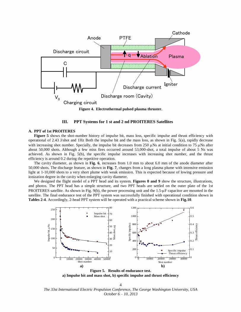
Pulsed plasma thrusters, as shown in Fig. 4, are expected to be used as a thruster for small/nano satellites. The
PPT has some features superior to other kinds of electric propulsion. It has no sealing part, simple structure and high
reliability, which are benefits of using a solid propellant, mainly Teflon®
(poly-tetrafluoroethylene: PTFE). However,
performances of PPTs are generally low compared with other electric thrusters22-27
.
At Osaka Institute of Technology, the PPT has been studied since 2003 in order to understand physical
phenomena and improve thrust performances with both experiments and numerical simulations. We mainly studied
electrothermal-acceleration-type PPTs, which generally had higher thrust-to-power ratios (impulse bit per unit initial
energy stored in capacitors) and higher thrust efficiencies than electromagnetic-acceleration-type PPTs. Although
the electrothermal PPT has lower specific impulse than the electromagnetic PPT, the low specific impulse is not a
significant problem as long as the PPT uses solid propellant, because there is no tank nor valve for liquid or gas
propellant which would be a large weight proportion of a thruster system.
Specifications Value
Mass 14.5kg
Dimensions Cube, 290mm on a side
Electrical power 10W
Altitude 660km
Development period 3year
Life time More than one year
Orbit Sun-synchronous orbit
Launch vehicle PSLV C-21
The 33st International Electric Propulsion Conference, The George Washington University, USA
October 6 – 10, 2013
4
C
PTFECathode
Anode
Plasma
V0
Ablationq
IgniterDischarge current
Charging circuit
Discharge circuit
Discharge room (Cavity)
Figure 4. Electrothermal pulsed plasma thruster.
III. PPT Systems for 1 st and 2 nd PROITERES Satellites
A. PPT of 1st PROITERES
Figure 5 shows the shot-number history of impulse bit, mass loss, specific impulse and thrust efficiency with
operational of 2.43 J/shot and 1Hz Both the impulse bit and the mass loss, as shown in Fig. 5(a), rapidly decrease
with increasing shot number. Specially, the impulse bit decreases from 250 Ns at initial condition to 75 Ns after
about 50,000 shots. Although a few miss fires occurred around 53,000-shot, a total impulse of about 5 Ns was
achieved. As shown in Fig. 5(b), the specific impulse increases with increasing shot number, and the thrust
efficiency is around 0.2 during the repetitive operation.
The cavity diameter, as shown in Fig. 6, increases from 1.0 mm to about 6.0 mm of the anode diameter after
50,000 shots. The discharge feature, as shown in Fig. 7, changes from a long plasma plume with intensive emission
light at 1-10,000 shots to a very short plume with weak emission. This is expected because of lowing pressure and
ionization degree in the cavity when enlarging cavity diameter.
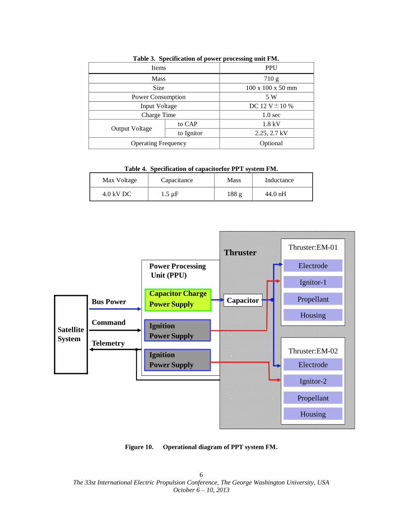
We designed the flight model of a PPT head and its system. Figures 8 and 9 show the structure, illustrations,
and photos. The PPT head has a simple structure, and two PPT heads are settled on the outer plate of the 1st
PROITERES satellite. As shown in Fig. 9(b), the power processing unit and the 1.5-F capacitor are mounted in the
satellite. The final endurance test of the PPT system was successfully finished with operational condition shown in
Tables 2-4. Accordingly, 2-head PPT system will be operated with a practical scheme shown in Fig.10.
a) b)
Figure 5. Results of endurance test.
a) Impulse bit and mass shot, b) specific impulse and thrust efficiency
Imp
uls
e b
it,
s
Shot number
Mas
s sh
ot,
g
Impulse bit Mass shot
0 10000 20000 30000 40000 500000
50
100
150
200
250
0
10
20
30
40
50
60
70
80
Spec
ific
im
pul
se,s
Th
rust
eff
icie
ncy
Shot number
Specific impulse Thrust efficiency
0 10000 20000 30000 400000
200
400
600
800
1000
1200
0
0.1
0.2
0.3
0.4
0.5
0.6

The 33st International Electric Propulsion Conference, The George Washington University, USA
October 6 – 10, 2013
5
Figure 6. Change of cavity diameter a) b)
before and after 50,000-shots. Figure 7. Feature of plasma plume. a) 1-10,000 shots, b) 50,000shots.
Figure 8. Inner structure of PPT head.
a) b)
Figure 9. PPT flight-model parts.
a) Photos of PPT head, b) Power processing unit and 1.5-µF capacitor of flight model of PPT
Table 2. Specification of PPT head FM.
Items PPT
Mass 138 g
Size 30(h) x 50(w) x 40(d) mm
Cavity length 10 mm
Cavity diameter 1.0 mm
Ignitor hole diameter 3.0 mm
Ignitor hole position 3.0 mm
Nozzle length 19 mm
Nozzle diameter 5.7 mm
Nozzle half angle 20 deg
Material propellant PTFE
Material anode Cu
Material cathode SUS304
Material body Polycarbonate
PTFE
Cathode: SUS304
Anode: Copper
Body: Polycarbonate
Holder: Polycarbonate
50,00010,000
φ1mm φ6mm
1-10,000shots 50,000shots-
Power Processing Unit
Capacitor
The 33st International Electric Propulsion Conference, The George Washington University, USA
October 6 – 10, 2013
6
Table 3. Specification of power processing unit FM.
Items PPU
Mass 710 g
Size 100 x 100 x 50 mm
Power Consumption 5 W
Input Voltage DC 12 V±10 %
Charge Time 1.0 sec
Output Voltage to CAP 1.8 kV
to Ignitor 2.25, 2.7 kV
Operating Frequency Optional
Table 4. Specification of capacitorfor PPT system FM.
Max Voltage Capacitance Mass Inductance
4.0 kV DC 1.5 µF 188 g 44.0 nH
Figure 10. Operational diagram of PPT system FM.
PPT研究開発概要
Bus Power
Command
Telemetry
Capacitor
Satellite
System
Thruster
Power Processing
Unit (PPU)
Capacitor Charge
Power Supply
Ignition
Power Supply
Ignition
Power Supply
Electrode
Ignitor-1
Thruster:EM-01
Housing
Propellant
Electrode
Ignitor-2
Thruster:EM-02
Housing
Propellant
The 33st International Electric Propulsion Conference, The George Washington University, USA
October 6 – 10, 2013
7
B. PPT of 2nd PROITERES
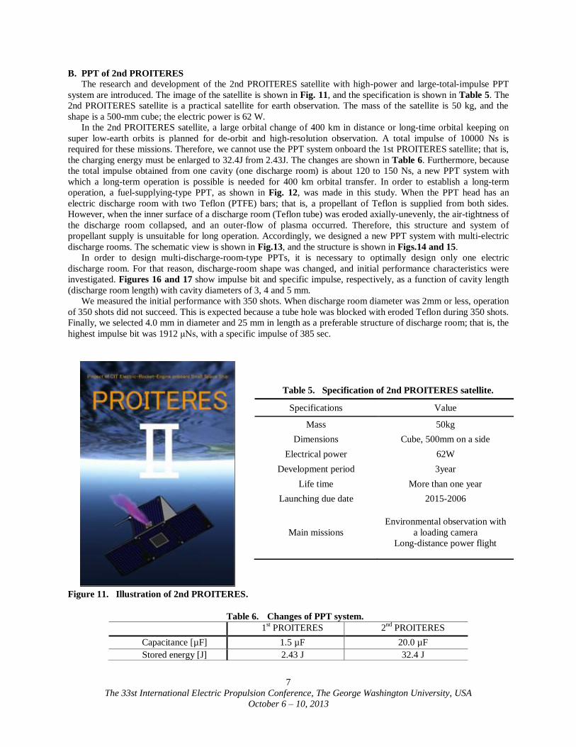
The research and development of the 2nd PROITERES satellite with high-power and large-total-impulse PPT
system are introduced. The image of the satellite is shown in Fig. 11, and the specification is shown in Table 5. The
2nd PROITERES satellite is a practical satellite for earth observation. The mass of the satellite is 50 kg, and the
shape is a 500-mm cube; the electric power is 62 W.
In the 2nd PROITERES satellite, a large orbital change of 400 km in distance or long-time orbital keeping on
super low-earth orbits is planned for de-orbit and high-resolution observation. A total impulse of 10000 Ns is
required for these missions. Therefore, we cannot use the PPT system onboard the 1st PROITERES satellite; that is,
the charging energy must be enlarged to 32.4J from 2.43J. The changes are shown in Table 6. Furthermore, because
the total impulse obtained from one cavity (one discharge room) is about 120 to 150 Ns, a new PPT system with
which a long-term operation is possible is needed for 400 km orbital transfer. In order to establish a long-term
operation, a fuel-supplying-type PPT, as shown in Fig. 12, was made in this study. When the PPT head has an
electric discharge room with two Teflon (PTFE) bars; that is, a propellant of Teflon is supplied from both sides.
However, when the inner surface of a discharge room (Teflon tube) was eroded axially-unevenly, the air-tightness of
the discharge room collapsed, and an outer-flow of plasma occurred. Therefore, this structure and system of
propellant supply is unsuitable for long operation. Accordingly, we designed a new PPT system with multi-electric
discharge rooms. The schematic view is shown in Fig.13, and the structure is shown in Figs.14 and 15.
In order to design multi-discharge-room-type PPTs, it is necessary to optimally design only one electric
discharge room. For that reason, discharge-room shape was changed, and initial performance characteristics were
investigated. Figures 16 and 17 show impulse bit and specific impulse, respectively, as a function of cavity length
(discharge room length) with cavity diameters of 3, 4 and 5 mm.
We measured the initial performance with 350 shots. When discharge room diameter was 2mm or less, operation
of 350 shots did not succeed. This is expected because a tube hole was blocked with eroded Teflon during 350 shots.
Finally, we selected 4.0 mm in diameter and 25 mm in length as a preferable structure of discharge room; that is, the
highest impulse bit was 1912 μNs, with a specific impulse of 385 sec.
Table 5. Specification of 2nd PROITERES satellite.
Figure 11. Illustration of 2nd PROITERES.
Table 6. Changes of PPT system.
Specifications Value
Mass 50kg
Dimensions Cube, 500mm on a side
Electrical power 62W
Development period 3year
Life time More than one year
Launching due date 2015-2006
Main missions
Environmental observation with
a loading camera
Long-distance power flight
1st PROITERES 2
nd PROITERES
Capacitance [µF] 1.5 µF 20.0 µF
Stored energy [J] 2.43 J 32.4 J

The 33st International Electric Propulsion Conference, The George Washington University, USA
October 6 – 10, 2013
8
Figure 12. Fuel-supplying- type PPT.
Figure 13. PPT with multi-discharge room. Figure 14. Structure of multi-discharge-room PPT.
Figure 15. Structure of laboratory-model multi-discharge-room PPT.
Cathode
Anode
PTFE

The 33st International Electric Propulsion Conference, The George Washington University, USA
October 6 – 10, 2013
9
Figure 16. Impulse bit vs cavity length. Figure 17. Specific Impulse vs cavity length.
IV. Hall Thruster for 3rd PROITERES Satellite
The 3rd satellite of PROITERES28-30
series is a 50-kg moon-exploration satellite with cylindrical-type Hall
thruster system for powered flight from the low earth orbit to the moon orbit. That is very exciting mission. The Hall
thruster system will produce specific impulses of 1500-2000 sec at xenon mass flow rates of 0.1-0.3 mg/s with an
input power of 30 W. The trip time to the moon is within 3 years.
We developed an original low-power CHT named TCHT-4 in which permanent magnet is used in exchange for
inner coils. The optimized TCHT-4 had a high efficiency of 30.1% at an input power of 55.5W; the thrust was 0.9
mN, and the specific impulse was 1864 sec. However, TCHT-4 had unstable operation at 170 sec, and significant
performance degradation. This is because the inner permanent magnet was degraded by discharge room's
overheating. Therefore, we developed a new CHT named “TCHT-5” in which discharge room length and magnetic
poles length can be changed. The performance characteristics of TCHT-5 are measured.
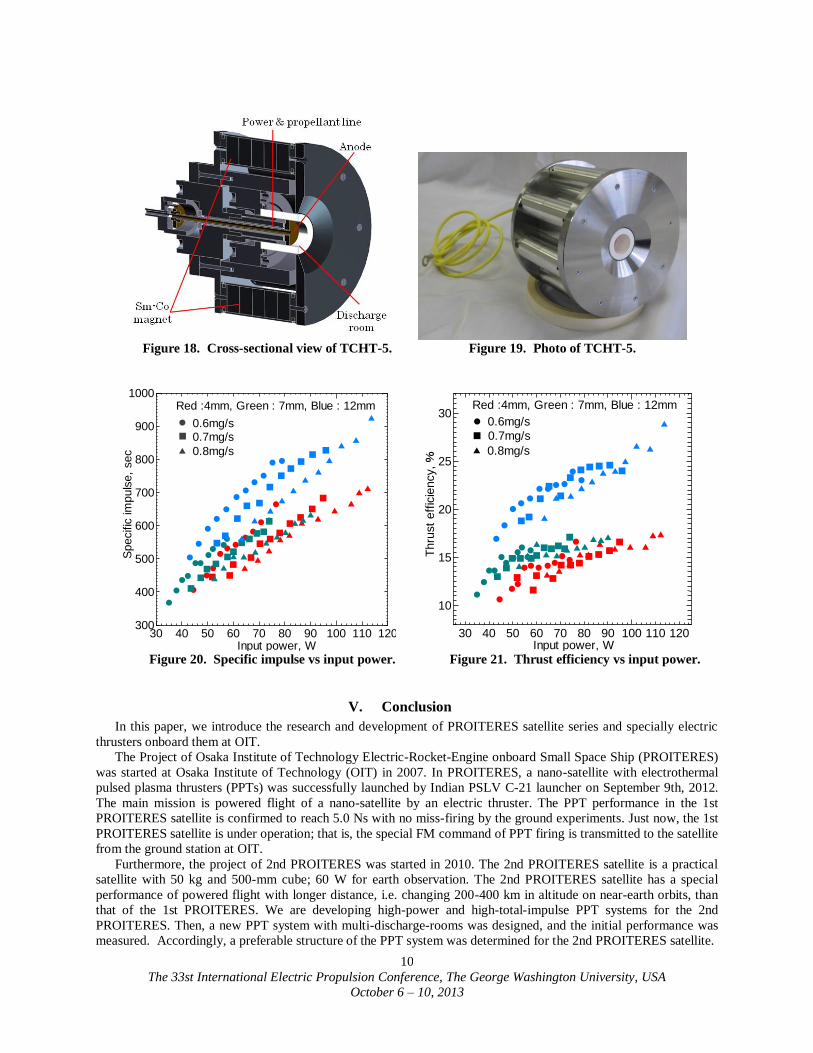
Figures 18 and 19 show the TCHT-5 Hall thruster. The anode is located at the upstream end of the circular
cross-sectional part. The discharge chamber is made of boron nitride (BN), and the inner diameter is 14mm. TCHT-
5 can change the anode position and discharge room length by an inside screw. In TCHT-5 Sm-Co permanent
magnets are employed because the degradation of magnetic property by heating is relatively small. The magnetic
field has an axial component, and the strength is the highest near the anode located at the upstream region. The
discharge room length is 7 mm, and the maximum magnetic flux density is 184 mT. Figures 20 and 21 show the
characteristics of the specific impulse and the thrust efficiency, respectively, as a function of input power. When the
mass flow rate is 0.6 mg/s, both the specific impulse and thrust efficiency have high performance in 50-60W range.
Especially, when the magnetic poles length is 12mm, the specific impulse and thrust efficiency are higher 20%
performance than other length.
As a result, a stable operation was achieved, and the minimum input-power operation of TCHT-5 had a specific
impulse of 648.3 sec with 57.3W, and also thrust efficiency was 22.1%. TCHT-5 was lower performance than
TCHT-4; it is considered to be insufficiently ExB drift in the discharge room, because the radial magnetic field is
weaker than expected. In the future, the optimal magnetic field strength condition will be necessary to be examined.
Imp
uls
e B
it,
Ns
Cavity Length, mm
3mm4mm5mm
Cavity Diameter
10 15 20 250
500
1000
1500
2000
2500
3000
Sp
ecif
ic I
mp
uls
e, se
c
Cavity Length, mm
3mm4mm5mm
Cavity Diameter
10 15 20 250
250
500
750
1000
1250
The 33st International Electric Propulsion Conference, The George Washington University, USA
October 6 – 10, 2013
10
Figure 18. Cross-sectional view of TCHT-5. Figure 19. Photo of TCHT-5.
30 40 50 60 70 80 90 100 110 120300
400
500
600
700
800
900
1000
Input power, W
Specific
im
puls
e,
sec
Red :4mm, Green : 7mm, Blue : 12mm
0.6mg/s0.7mg/s
0.8mg/s
30 40 50 60 70 80 90 100 110 120
10
15
20
25
30
Input power, W
Thru
st
eff
icie
ncy, %
Red :4mm, Green : 7mm, Blue : 12mm
0.6mg/s
0.7mg/s
0.8mg/s
Figure 20. Specific impulse vs input power. Figure 21. Thrust efficiency vs input power.
V. Conclusion
In this paper, we introduce the research and development of PROITERES satellite series and specially electric
thrusters onboard them at OIT.
The Project of Osaka Institute of Technology Electric-Rocket-Engine onboard Small Space Ship (PROITERES)
was started at Osaka Institute of Technology (OIT) in 2007. In PROITERES, a nano-satellite with electrothermal
pulsed plasma thrusters (PPTs) was successfully launched by Indian PSLV C-21 launcher on September 9th, 2012.
The main mission is powered flight of a nano-satellite by an electric thruster. The PPT performance in the 1st
PROITERES satellite is confirmed to reach 5.0 Ns with no miss-firing by the ground experiments. Just now, the 1st
PROITERES satellite is under operation; that is, the special FM command of PPT firing is transmitted to the satellite
from the ground station at OIT.
Furthermore, the project of 2nd PROITERES was started in 2010. The 2nd PROITERES satellite is a practical
satellite with 50 kg and 500-mm cube; 60 W for earth observation. The 2nd PROITERES satellite has a special
performance of powered flight with longer distance, i.e. changing 200-400 km in altitude on near-earth orbits, than
that of the 1st PROITERES. We are developing high-power and high-total-impulse PPT systems for the 2nd
PROITERES. Then, a new PPT system with multi-discharge-rooms was designed, and the initial performance was
measured. Accordingly, a preferable structure of the PPT system was determined for the 2nd PROITERES satellite.

The 33st International Electric Propulsion Conference, The George Washington University, USA
October 6 – 10, 2013
11
The 3rd satellite of PROITERES is a 50-kg moon-exploration satellite with a cylindrical-type Hall thruster
system for powered flight from the low earth orbit to the moon orbit. An original cylindrical Hall thruster is under
development for that exciting mission.
References 1 Ikeda, T., Yamada, M., Shimizu, M., Fujiwara, T., Tahara, H. and Satellite R&D Team of Students and Faculty Members of
OIT,” Research and Development of an Attitude Control System for Osaka Institute of Technology Electric-Rocket-Engine
onboard Small Space Ship,” 27th International Symposium on Space Technology and Science, Tsukuba, Japan, 2009, Paper No.
ISTS 2009-s-02f. 2 Yamada, M., Ikeda, T., Shimizu, M., Fujiwara, T., Tahara, H. and Satellite R&D Team of Students and Faculty Members of
OIT,” Progress of Project of Osaka Institute of Technology Electric-Rocket-Engine onboard Small Space Ship,” 27th
International Symposium on Space Technology and Science, Tsukuba, Japan, 2009, Paper No. ISTS 2009-s-05f. 3 Yamada, M., Ikeda, T., Fujiwara, T. and Tahara, H.,” Project of Osaka Institute of Technology Electric-Rocket-Engine
onboard Small Space Ship,” 31st International Electric Propulsion Conference, University of Michigan, Ann Arbor, Michigan, USA, 2009, Paper No. IEPC-2009-051.
4 Takagi, H., Yamamoto, T., Ishii, Y. and Tahara, H.,” Performance Enhancement of Electrothermal Pulsed Plasma Thrusters
for Osaka Institute of Technology Electric-Rocket-Engine onboard Small Space Ship,” 27th International Electric Propulsion
Conference, Tsukuba, Japan, 2009, Paper No. ISTS 2009-b-16. 5 Takagi, H., Yamamoto, T., Ishii, Y. and Tahara, H.,” Performance Enhancement of Electrothermal Pulsed Plasma Thrusters
for Osaka Institute of Technology Electric-Rocket-Engine onboard Small Space Ship,” 31th International Electric Propulsion
Conference, University of Michigan, Ann Arbor, Michigan, USA, 2009, Paper No. IEPC-2009-254. 6 Araki, S., Ikeda, T., Ozaki, J., Nishizawa, M,. Inoue, Y., Iguchi, T.,\ and Tahara, H.,” Development of an Attitude Control
System for Nano-Satellite PROITERES,” 28th International Symposium on Space Technology and Science, Okinawa
Convention Center, Ginowan-City, Okinawa, Japan, 2011, Paper No. ISTS 2011-j-21s. 7 Nishizawa, M., Ikeda, T., Ozaki, J., Tahara, H., Watanabe, Y., Enoguchi, A. and Takryama, N.," Development of a High-
Resolution Camera System onboard Nano-Satellite PROITERES," 28th International Symposium on Space Technology and Science, Okinawa Convention Center, Ginowan-City, Okinawa. Japan, 2011, Paper No. ISTS 2011-n-08.
8 Ikeda, T., Ozaki, J., Araki, S., Nishizawa, M., Inoue, Y., Iguchi, T., Tahara, H., and Watanabe, Y.," Research and
Development of Nano-Sa0tellite PROITERES Series at Osaka Institute of Technology," 28th International Symposium on Space
Technology and Science" Okinawa Convention Center, Ginowan-City, Okinawa, Japan, 2011, Paper No. ISTS 2011-j-21. 9 Naka, M., Tanaka, M., Tahara, H., Watanabe, Y. and Wakizono, T.," Development of Electrothermal Pulsed Plasma
Thruster System Flight-Model onboard Nano-Satellite PROITERES," 28th International Symposium on Space Technology and
Science" Okinawa Convention Center, Ginowan-City, Okinawa, Japan, 2011, Paper No. ISTS 2011-b-03. 10 Ozaki, J., Ikeda, T., Araki, S., Nishizawa, M., Inoue, Y., Iguchi, T., Tahara, H. and Watanabe, Y.," Development of Nano-
Satellite PROITERES with Electric Rocket Engines at Osaka Institute of Technology," 28th International Symposium on Space
Technology and Science, Okinawa Convention Center, Ginowan-City, Okinawa, Japan, 2011, Paper No. ISTS 2011-b-13. 11 Tahara, H., Ishii, Y., Tanaka, M., Naka, M. and Watanabe, Y.," Flowfield Calculation of Electrothermal Pulsed Plasma
Thrusters for the PROITERES Satellite," 32nd International Electric Propulsion Conference, Kurhaus, Wiesbaden, Germany, 2011, Paper No. IEPC-2011-037.
12 Ozaki, J., Ikeda, T., Fujiwara, T., Nishizawa, M., Araki, S., Tahara, H. and Watanabe, Y.," Development of Osaka Institute
of Technology Nano-Satellite “PROITERES” with Electrothermal Pulsed Plasma Thrusters," 32nd International Electric
Propulsion Conference, Kurhaus, Wiesbaden, Germany , 2011, Paper No. IEPC-2011-035. 13 Naka, M., Hosotani, R., Tahara, H. and Watanabe, Y.," Development of Electrothermal Pulsed Plasma Thruster System
Flight-Model for the PROITERES Satellite," 32nd International Electric Propulsion Conference, Kurhaus, Wiesbaden, Germany,
2011, Paper No. IEPC-2011-034. 14 Kawamura, T., Fujiwara, K., Uemura, K., Muraoka, R., Chen, H., Kisaki, S., Tanaka, M., Tahara, H. and Wakizono, T.,"
Research and Development of Electrothermal Pulsed Plasma Thruster Systems for Osaka Institute of Technology PROITERES
Nano-Satellite Series," 29th International Symposium on Space Technology and Science, Nagoya Congress Center, Nagoya-City,
Aichi, Japan, 2013, Paper No. ISTS-2013-055p. 15 Ikeda, T., Ozaki, J., Araki, S., Nishizawa, M., Inoue, Y., Iguchi, T., Tahara, H. and Watanabe, Y.," Research and
Development of Nano-Satellite PROITERES Series at Osaka Institute of Technology," 28th International Symposium on Space
Technology and Science" Okinawa Convention Center, Ginowan-City, Okinawa, Japan, 2011, Paper No. ISTS 2011-j-21. 16 Inoue, Y., Ozaki, J., Ikeda, T., Tahara, H. and Watanabe, Y.," Research and Development of Osaka Institute of Technology
Nano-Satellite “PROITERES” with Electrothermal Pulsed Plasma Thrusters," Asian Joint Conference on Propulsion and Power 2012, Grand New World Hotel, Xi'an, China, 2012, Paper No. AJSPP2012-005.
17 Kisaki, S., Muraoka, R., Chen, H., Tanaka, M., Egami, N., Ikeda, T., Tahara, H. and Wakizono, T.," Research and
Development of Osaka Institute of Technology PROITERES Nano-Satellite Series with Electrothermal Pulsed Plasma Thruster
Systems," 29th International Symposium on Space Technology and Science, Nagoya Congress Center, Nagoya-City, Aichi, Japan, 2013, Paper No. ISTS 2013-b-15.
18 Egami, N., Matsuoka, T., Sakamoto, M., Inoue, Y., Ikeda, T. and Tahara, H.,” R&D, Launch and Initial Operation of the
Osaka Institute of Technology 1st PROITERES Nano-Satellite and Development of the 2nd and 3rd Satellites," 29th

The 33st International Electric Propulsion Conference, The George Washington University, USA
October 6 – 10, 2013
12
International Symposium on Space Technology and Science, Nagoya Congress Center, Nagoya-City, Aichi, Japan, 2013, Paper
No. ISTS 2013-f-12. 19 Egami, N., Matsuoka, T., Sakamoto, M., Inoue, Y., Ikeda T. and Tahara, H.,“ R&D,Launch and Initial Operation of the
Osaka Institute of Technology 1st PROITERES Nano-Satellite with Electorothermal Pulsed Plasma Thrusters and Development
of the 2nd satellite,” 33nd International Electric Propulsion Conference, George Washington University, Washington, D.C., USA,
2013, Paper No. IEPC-2013-100. 20 Kamimura, T., Yamasaki, K., Egami, N., Matsuoka, T., Sakamoto, M., Inoue, Y., Ikeda, T. and Tahara, H.," Final
Checking Process and Launch of the Osaka Institute of Technology 1st PROITERES Nano-Satellite Using Indian PSLV Rocket
C-21," 29th International Symposium on Space Technology and Science, Nagoya Congress Center, Nagoya-City, Aichi, Japan,
2013, Paper No. ISTS 2013-f-48p. 21 Muraoka, R., Chen, H., C., Kisaki, S., Tanaka, K., Tahara, H. and Wakizono, T.," Performance Characteristics of
Electrothermal Pulsed Plasma Thruster Systems onboard Osaka Institute of Technology PROITERES Nano-Satellite Series,"
29th International Symposium on Space Technology and Science, Nagoya Congress Center, Nagoya-City, Aichi, Japan, 2013,
Paper No. ISTS 2013-b-13. 22 Edamitsu, T., Tahara, H. and Yoshikawa, T.,” Performance Characteristics of a Coaxial Pulsed Plasma Thruster with PTFE
Cavity,” Proceedings of Asian Joint Conferences on Propulsion and Power 2004, 2004, pp.324-334. 23 Rysanek, F. and Burton, R. L.,” Performance and Heat Loss of a Coaxial Teflon Pulsed Thruster,” 27th International
Electric Propulsion Conference, Pasadena, California, USA, 2001, Paper No. IEPC-01-151. 24 Burton, R. L. and Turchi, P. J.,” Pulsed Plasma Thruster,” Journal of Propulsion and Power, Vol.14, No.5, 1998, pp.716-
735.
25 Burton, R. L., Wilson, M. J. and Bushman, S. S.,” Energy Balance and Efficiency of the Pulsed Plasma Thruster,” AIAA
Paper No. 98-3808, 1988. 26 Edamitsu, T., Tahara, H. and Yoshikawa, T.,” Performance Measurement and Flowfield Calculation of a Pulsed Plasma
Thruster with a PTFE Cavity,” Asian Joint Conference on Propulsion and Power 2005, Kitakyushu International Conference
Center, Kitakyushu, Japan, 2005, Paper No. AJCPP2005-22083. 27 Edamitsu, T. and Tahara, H.,” Performance Measurement and Flowfield Calculation of an Electrothermal Pulsed Plasma
Thruster with a Propellant Feeding Mechanism,” 29th International Electric Propulsion Conference, Princeton University,
Princeton, New Jersey, USA, 2005, Paper No. IEPC-05-105. 28 Togawa, K., Nose, M., Sugimoto, N., Nishida, T., Ikeda, T., Tahara, H. and Watanabe, Y.," Performance Characteristics of
Very Low Power Cylindrical Hall Thrusters for Nano-Satellites," 28th International Symposium on Space Technology and Science, Okinawa Convention Center, Ginowan-City, Okinawa, Japan, 2011, Paper No. ISTS 2011-b-22.
29 Ikeda, T., Togawa, K., Nishida, T., Tahara, H. and Watanabe, Y.," Research and Development of Very Low Power
Cylindrical Hall Thrusters for Nano-Satellites," 32nd International Electric Propulsion Conference, Kurhaus, Wiesbaden,
Germany, 2011, Paper No. IEPC-2011-39. 30 Ikeda, T., Togawa, K., Sugimoto, N., Mito, Y., Yamamoto, R., Kato, Y. and Tahara, H.," Research and Development of
Cylindrical Hall Thrusters for Small Spacecraft," 29th International Symposium on Space Technology and Science, Nagoya
Congress Center, Nagoya-City, Aichi, Japan, 2013, Paper No. ISTS 2013-b-20.