effects of electric charge in capacitors on pulsed plasma...
TRANSCRIPT
The 33st International Electric Propulsion Conference, The George Washington University, USA
October 6 – 10, 2013
1
Effects of Electric Charge in Capacitors on Pulsed Plasma Thruster Performance with External Magnetic Field
IEPC-2013-254
Presented at the 33rd International Electric Propulsion Conference, The George Washington University • Washington, D.C. • USA
October 6 – 10, 2013
Shinya Mori1, Takahiro Shindo1, Keisuke Tajiri1, Yuya Tamugi1, Junichiro Aoyagi2 and Haruki Takegahara3 Tokyo Metropolitan University Hino, Tokyo, 191-0065, Japan
Abstract: To evaluate the effects of external magnetic field on pulsed plasma thruster, impulse bit caused by external magnetic field was calculated using ideal slug mode model. This calculation indicates impulse bit caused by external magnetic field depends on electric charge in capacitors, not stored energy. In order to investigate this relation, impulse bit was measured by the change of capacitance and charge up voltage at fixed input energy. From this experiment, dependence of impulse bit on electric charge was confirmed; impulse bit was increased linearly with electric charge. However, measured values were much smaller than calculated values; it was caused by difference of external magnetic field distribution between calculations and experiments. Moreover, calculations did not contain back electro motive force by moving current sheet and interaction between impulse bit caused by self-induced magnetic field and external magnetic field.
Nomenclature Fext = electromagnetic force by external magnetic field R = resistance l = distance from propellant surface to current sheet Isp = specific impulse δ = current sheet thickness N = number of pulses h = gap between electrodes g = gravity acceleration d = electrodes width η = thrust efficiency j = current density Bext = magnetic flux density of external magnetic field J = current Ibit,ext = impulse bit by external magnetic field τ = discharge time C = capacitance V0 = initial voltage Q0 = initial electric charge in capacitors E = input energy Ibit,ind = impulse bit by self-induced magnetic field L = inductance Δm = mass shot mi = propellant mass before experiment mf = propellant mass after experiment
1 Graduate Student, Department of Aerospace Engineering, TMU, [email protected] 2 Assistant Professor, Department of Aerospace Engineering, TMU, [email protected] 3 Professor, Department of Aerospace Engineering, TMU, [email protected]
The 33st International Electric Propulsion Conference, The George Washington University, USA
October 6 – 10, 2013
2
I. Introduction ulsed Plasma Thruster (PPT) is one of electric propulsion system. PPT needs neither tank nor mechanical valves because it uses solid propellant. Therefore, PPT has simple structure and high reliability. From this aspect, PPT
is an attractive thruster for small satellites.1 However, electromagnetic PPT has low thrust-to-power ratio and thrust efficiency compared with other electric propulsion systems.2 Thus, increasing in these performances is needed to install PPT on small satellites. Appling external magnetic field for PPT is one of the ways to increase its thrust performances. Effects of external magnetic field on PPT were studied from late 1970s to early 1980s.3,4 According to these studies, in the case of accelerating magnetic fields (external magnetic field has same direction as self-induced magnetic field), specific impulse and thrust efficiency were improved as the magnitude of magnetic field increased, though the impulse bits were decreased. And in the case of retarding magnetic fields (external magnetic field has opposite direction as self-induced magnetic field), mass shot was increased. As a result, impulse bit was also increased. In summary, electromagnetic force was increased under accelerating magnetic field, while electrothermal force was increased under retarding magnetic field. Therefore, applying magnetic field improves PPT performance. Although applying magnetic field has these advantages, external magnetic field has never been applied to PPT systems because of its weight. Recently, magnets become smaller due to the increase in maximum energy product of magnets.5 Previous studies reported that magnitude of external magnetic field affects on impulse bit, mass shot, specific impulse and thrust efficiency; these were investigated experimentally. On the other hand, this study approaches the effect of external magnetic field with simple calculation. Calculations are described in section II, and experimental results are described in section IV.
II. Calculation of Impulse Bit Caused by External Magnetic Field In order to evaluate impulse bit caused by external magnetic field, simple calculations were carried out. In this
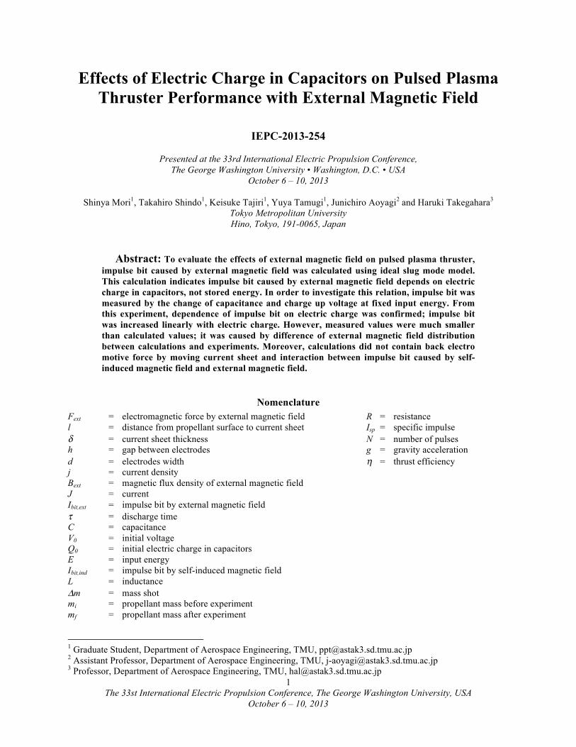
section, calculation model and simple calculation were described. A) Calculation Model The calculation model is shown in Fig.1. In this model, PPT has parallel rectangular electrodes and breech-fed system. Therefore, acceleration mechanism is slug mode model. Current sheet width d and height h is same with electrodes width and gap, respectively. And, current sheet thickness δ is negligible value comparison with discharge channel length l. Current density in current sheet j is uniform, thus j = J/(δ・d), and it has only y-axis direction. External magnetic field has only z-axis direction and its distribution is uniform everywhere in thruster head. Therefore, in this model, j×B Lorentz force has only x-axis direction.
j�Propellant�
Cathode�
Anode�
Bext�
Ignitor�
h�
l� δ�
d�x�
y�
z�
Figure 1. Calculation model.
B) Simple Calculations of Impulse Bit Caused External Magnetic Field In order to evaluate impulse bit caused by external magnetic field, simple calculations were carried out. Thrust and impulse bit of PPT with external magnetic field are combination with self-induced electromagnetic force and external electromagnetic force. Therefore, thrust and impulse bit are written as below.
F = Find +Fext (1)
P
The 33st International Electric Propulsion Conference, The George Washington University, USA
October 6 – 10, 2013
3
Ibit = Ibit ,ind + Ibit ,ext (2)
In slug mode model, self-induced electromagnetic force and impulse bit are written as follows.
Find = j ×Bind dx dydz =
12dLdx
J 20
d∫0
h∫l
l+δ∫
(3)
Ibit ,ind =
12dLdx
J 2 dt 12dLdx
ER0
τ
∫ (4)
Equation (4) means that impulse bit caused by self-induced magnetic field depends on inductance gradient, stored energy E and total circuit resistance R. Hence, its thrust-to-power ratio is function of inductance gradient and resistance as shown in Eq. (5).
Ibit ,indE12dLdx1R (5)
On the other hand, thrust and impulse bit caused by external magnetic field are written as follows.
Fext = j × Bext dxdydz = hJBext0
d
∫0h
∫l
l+δ
∫ (6)
Ibit,ext = hBext J dt
0
τ
∫ = hBextQ0 = hBextCV0 (7) Equation (7) means that impulse bit caused by external magnetic field depends on electrode gap h, external magnetic flux density Bext and electric charge in capacitor Q0 (the product of capacitance C and charge up voltage V0). Therefore, its thrust-to-power ratio is functions of electrode gap, external magnetic flux density and charge up voltage as shown in Eq. (8).
Ibit ,extE
= 2hBextV0 (8)
Difference between Eq. (3) and Eq. (6) is magnetic field (self-induced magnetic field or external magnetic field). In Eq. (3), magnetic field is a function of current density j (Ampere’s law), thus the impulse bit shown in Eq. (4) has a J 2 term. On the other hand, external magnetic field is not function of j, thus impulse bit caused by external magnetic field depends on electric charge in capacitor, not stored energy. Thrust-to-power ratio of PPT with external magnetic field is sum of Eq. (5) and Eq. (8). Therefore, it is considered that thrust-to-power ratio is increased with the decrease of charge up voltage.
III. Experimental Apparatus and Conditions
A. Vacuum Facility and Measurement Apparatus All experiments were conducted in vacuum chamber. The vacuum chamber is 1.0 m in diameter and 1.8 m long.
The vacuum facility is evacuated with a rotary pump, mechanical booster pump and two turbo molecular pumps. Pressure in vacuum chamber was kept about 4×10⁻³ Pa. Impulse bit, discharge current and voltage were measured with target pendulum, rogowski coil and high voltage probe, respectively.
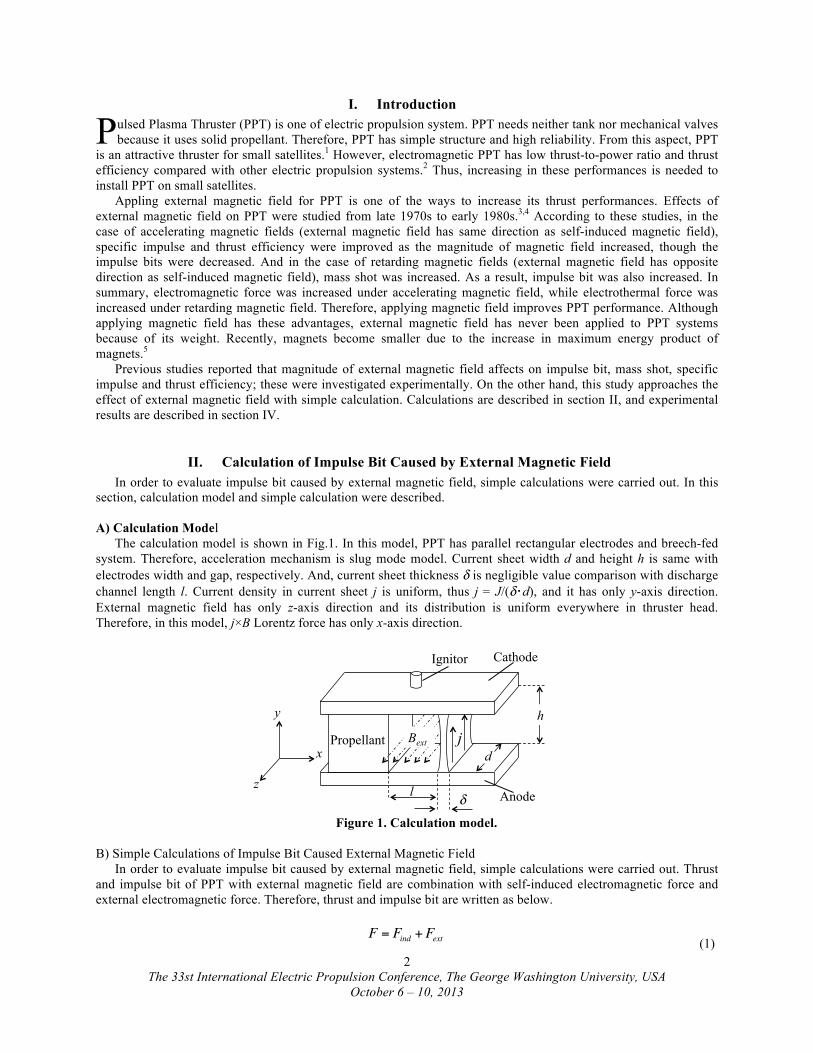
B. Thruster Head and External Magnet Schematic of thruster head is shown in Fig.2. Electrodes are made of cupper and these width, thickness,
electrode gap and discharge channel length are 5 mm, 3.5 mm, 10 mm and 20 mm, respectively. Propellant is made from polytetrafluoroethylene (PTFE) and has U-shaped geometry at discharge area. This shape prevents plasma diffusion from sides of discharge channel and protects permanent magnets from plasma plume.
The 33st International Electric Propulsion Conference, The George Washington University, USA
October 6 – 10, 2013
4
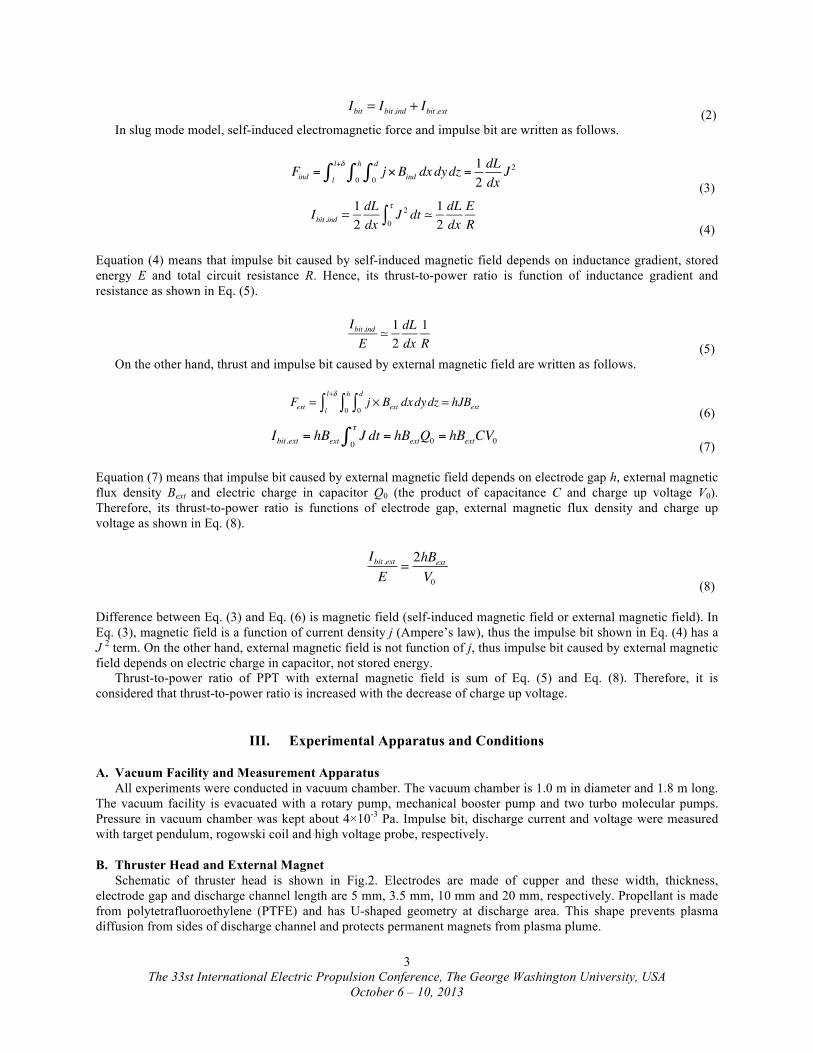
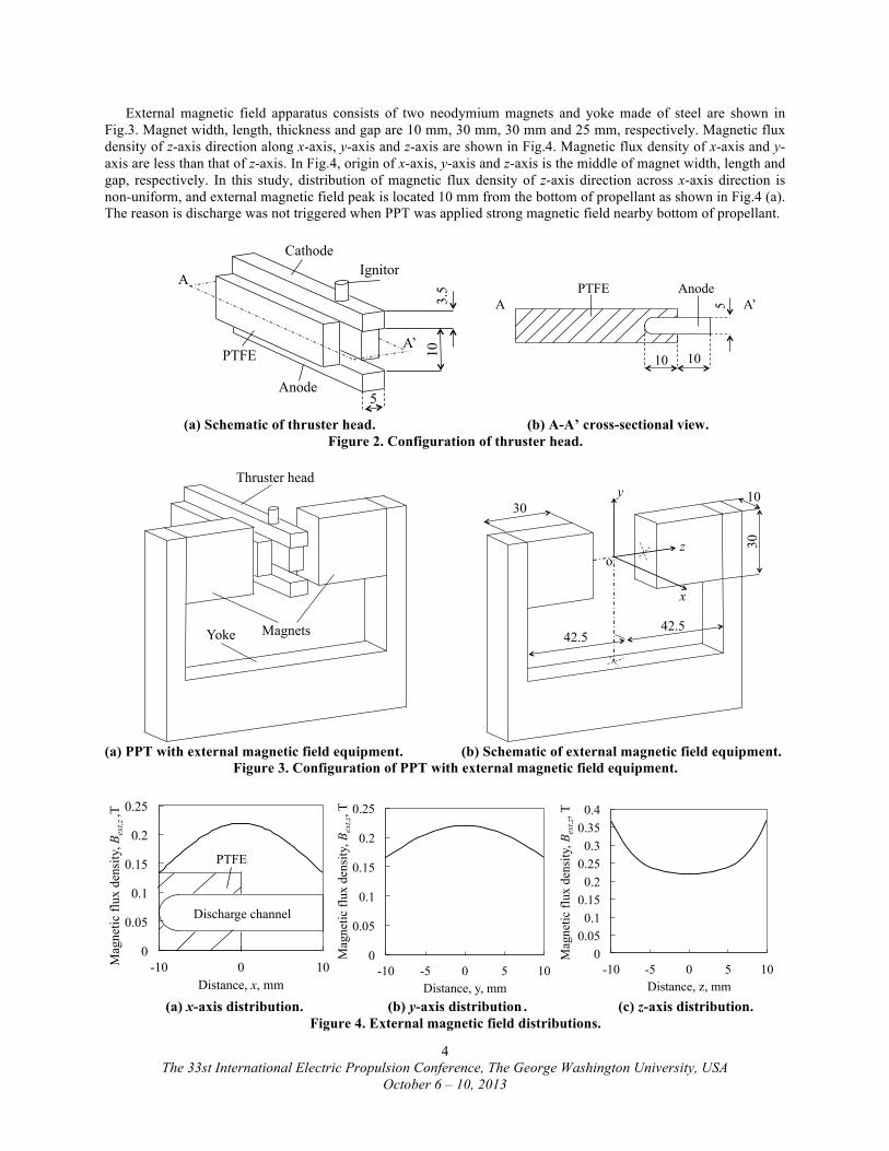
External magnetic field apparatus consists of two neodymium magnets and yoke made of steel are shown in Fig.3. Magnet width, length, thickness and gap are 10 mm, 30 mm, 30 mm and 25 mm, respectively. Magnetic flux density of z-axis direction along x-axis, y-axis and z-axis are shown in Fig.4. Magnetic flux density of x-axis and y-axis are less than that of z-axis. In Fig.4, origin of x-axis, y-axis and z-axis is the middle of magnet width, length and gap, respectively. In this study, distribution of magnetic flux density of z-axis direction across x-axis direction is non-uniform, and external magnetic field peak is located 10 mm from the bottom of propellant as shown in Fig.4 (a). The reason is discharge was not triggered when PPT was applied strong magnetic field nearby bottom of propellant.
Anode�
Cathode�Ignitor�
PTFE� 10�
3.5�
A�
A’�
5�
(a) Schematic of thruster head. (b) A-A’ cross-sectional view. Figure 2. Configuration of thruster head.
Thruster head�
Magnets�Yoke�
30�
30�
10�
x�
y�
z�o�
42.5�42.5�
(a) PPT with external magnetic field equipment. (b) Schematic of external magnetic field equipment.
Figure 3. Configuration of PPT with external magnetic field equipment.
0
0.05
0.1
0.15
0.2
0.25
-10 0 10 Mag
netic
flux
den
sity
, Bex
t,z ,T�
Distance, x, mm�
Discharge channel�
PTFE�
0
0.05
0.1
0.15
0.2
0.25
-10 -5 0 5 10
Mag
netic
flux
den
sity
, Bext,z
, T�
Distance, y, mm� (a) x-axis distribution. (b) y-axis distribution . (c) z-axis distribution.
Figure 4. External magnetic field distributions.
10� 10�
5�
Anode�PTFE�A� A’�
0 0.05
0.1 0.15
0.2 0.25
0.3 0.35
0.4
-10 -5 0 5 10
Mag
netic
flux
den
sity
, Bext,z
, T�
Distance, z, mm�
The 33st International Electric Propulsion Conference, The George Washington University, USA
October 6 – 10, 2013
5
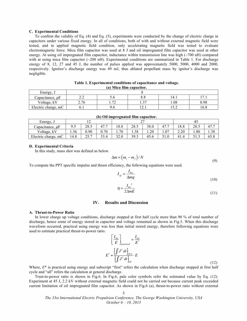
C. Experimental Conditions To confirm the validity of Eq. (4) and Eq. (5), experiments were conducted by the change of electric charge in
capacitors under various fixed energy. In all of conditions, both of with and without external magnetic field were tested, and in applied magnetic field condition, only accelerating magnetic field was tested to evaluate electromagnetic force. Mica film capacitor was used at 8 J and oil impregnated film capacitor was used at other energy. At using oil impregnated film capacitor, inductance within transmission line was high (~700 nH) compared with at using mica film capacitor (~200 nH). Experimental conditions are summarized in Table 1. For discharge energy of 8, 12, 27 and 45 J, the number of pulses applied was approximately 5000, 5000, 4000 and 2000, respectively. Ignitior’s discharge energy was 49 mJ, thus ablated propellant mass by ignitor’s discharge was negligible.
Table 1. Experimental conditions of capacitance and voltage.
(a) Mica film capacitor. Energy, J 8
Capacitance, µF 2.2 5.6 8.8 14.1 17.1 Voltage, kV 2.76 1.72 1.37 1.08 0.98
Electric charge, mC 6.1 9.6 12.1 15.2 16.8
(b) Oil impregnated film capacitor. Energy, J 12 27 45
Capacitance, µF 9.5 28.5 47.7 18.8 28.5 38.0 47.7 18.8 28.5 47.7 Voltage, kV 1.56 0.90 0.70 1.70 1.38 1.20 1.07 2.20 1.80 1.38
Electric charge, mC 14.8 25.7 33.4 32.0 39.3 45.6 51.0 41.4 51.3 65.8
D. Experimental Criteria In this study, mass shot was defined as below.
Δm = mi −mf( ) / N
(9) To compute the PPT specific impulse and thrust efficiency, the following equations were used.
Isp =
IbitΔmg (10)
η = Ibit
2
2ΔmE (11)
IV. Results and Discussion
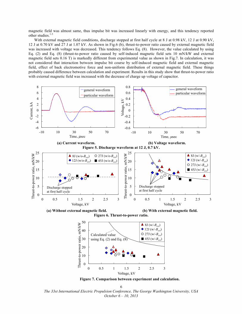
A. Thrust-to-Power Ratio In lower charge up voltage conditions, discharge stopped at first half cycle more than 90 % of total number of discharge, hence some of energy stored in capacitor and voltage remained as shown in Fig.5. When this discharge waveform occurred, practical using energy was less than initial stored energy, therefore following equations were used to estimate practical thrust-to-power ratio.
IbitE
⎡⎣⎢
⎤⎦⎥ practical
= IbitE*
E* =J 2 dt∫"# $
% firstJ 2 dt∫"# $
%all
⋅E
(12) Where, E* is practical using energy and subscript “first” refers the calculation when discharge stopped at first half cycle and “all” refers the calculation at general discharge. Trust-to-power ratio is shown in Fig.6. In Fig.6, pale color symbols refer the estimated value by Eq. (12). Experiment at 45 J, 2.2 kV without external magnetic field could not be carried out because current peak exceeded current limitation of oil impregnated film capacitor. As shown in Fig.6 (a), thrust-to-power ratio without external
The 33st International Electric Propulsion Conference, The George Washington University, USA
October 6 – 10, 2013
6
magnetic field was almost same, thus impulse bit was increased linearly with energy, and this tendency reported other studies.1-3 With external magnetic field conditions, discharge stopped at first half cycle at 8 J at 0.98 kV, 12 J at 0.90 kV, 12 J at 0.70 kV and 27 J at 1.07 kV. As shown in Fig.6 (b), thrust-to-power ratio caused by external magnetic field was increased with voltage was decreased. This tendency follows Eq. (8). However, the value calculated by using Eq. (2) and Eq. (8) (thrust-to-power ratio caused by self-induced magnetic field sets 10 mN/kW and external magnetic field sets 0.16 T) is markedly different from experimental value as shown in Fig.7. In calculation, it was not considered that interaction between impulse bit course by self-induced magnetic field and external magnetic field, effect of back electromotive force and non-uniform distribution of external magnetic field. These things probably caused difference between calculation and experiment. Results in this study show that thrust-to-power ratio with external magnetic field was increased with the decrease of charge up voltage of capacitor.
-6
-4
-2
0
2
4
6
8
-10 10 30 50 70
Cur
rent
, kA�
Time, µsec�
general waveform particular waveform
-0.6
-0.4
-0.2
0
0.2
0.4
0.6
0.8
-10 10 30 50 70
Volta
ge, k
V�
Time, µsec�
general waveform�particular waveform�
(a) Current waveform. (b) Voltage waveform.
Figure 5. Discharge waveform at 12 J, 0.7 kV.
0
5
10
15
20
25
0 0.5 1 1.5 2 2.5 3 Thru
st-to
-pow
er ra
tio, m
N/k
W�
Voltage, kV�
12J (w/o-Bext)� 45J (w/o-Bext)�27J (w/o-Bext)�8J (w/o-Bext)�
Discharge stopped at first half cycle�
0
5
10
15
20
25
0 0.5 1 1.5 2 2.5 3 Thru
st-to
-pow
er ra
tio, m
N/k
W�
Voltage, kV�
12J (w/-Bext)�
45J (w/-Bext)�27J (w/-Bext)�
8J (w/-Bext)�
Discharge stopped at first half cycle�
(a) Without external magnetic field. (b) With external magnetic field.
Figure 6. Thrust-to-power ratio. Figure 7. Comparison between experiment and calculation.
0
10
20
30
40
50
0 0.5 1 1.5 2 2.5 3 Thru
st-to
-pow
er ra
tio, m
N/k
W�
Voltage, kV�
12J (w/-Bext)�
45J (w/-Bext)�27J (w/-Bext)�
8J (w/-Bext)�
Calculated value using Eq. (2) and Eq. (8)�
The 33st International Electric Propulsion Conference, The George Washington University, USA
October 6 – 10, 2013
7
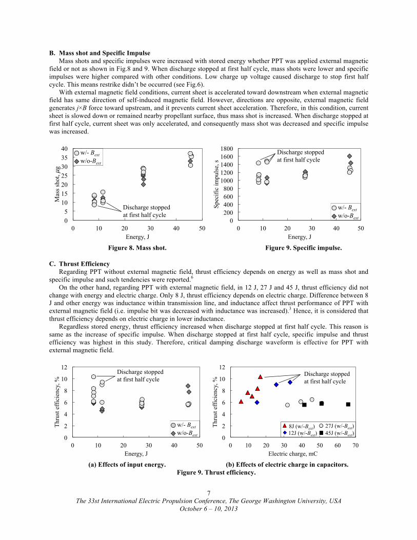
B. Mass shot and Specific Impulse Mass shots and specific impulses were increased with stored energy whether PPT was applied external magnetic field or not as shown in Fig.8 and 9. When discharge stopped at first half cycle, mass shots were lower and specific impulses were higher compared with other conditions. Low charge up voltage caused discharge to stop first half cycle. This means restrike didn’t be occurred (see Fig.6). With external magnetic field conditions, current sheet is accelerated toward downstream when external magnetic field has same direction of self-induced magnetic field. However, directions are opposite, external magnetic field generates j×B force toward upstream, and it prevents current sheet acceleration. Therefore, in this condition, current sheet is slowed down or remained nearby propellant surface, thus mass shot is increased. When discharge stopped at first half cycle, current sheet was only accelerated, and consequently mass shot was decreased and specific impulse was increased.
0 5
10 15 20 25 30 35 40
0 10 20 30 40 50
Mas
s sh
ot, µ
g�
Energy, J�
w/- Bext�w/o-Bext�
Discharge stopped at first half cycle�
0 200 400 600 800
1000 1200 1400 1600 1800
0 10 20 30 40 50
Spec
ific
impu
lse,
s�
Energy, J�
w/- Bext�w/o-Bext�
Discharge stopped at first half cycle�
Figure 8. Mass shot. Figure 9. Specific impulse.
C. Thrust Efficiency Regarding PPT without external magnetic field, thrust efficiency depends on energy as well as mass shot and specific impulse and such tendencies were reported.6 On the other hand, regarding PPT with external magnetic field, in 12 J, 27 J and 45 J, thrust efficiency did not change with energy and electric charge. Only 8 J, thrust efficiency depends on electric charge. Difference between 8 J and other energy was inductance within transmission line, and inductance affect thrust performance of PPT with external magnetic field (i.e. impulse bit was decreased with inductance was increased).3 Hence, it is considered that thrust efficiency depends on electric charge in lower inductance. Regardless stored energy, thrust efficiency increased when discharge stopped at first half cycle. This reason is same as the increase of specific impulse. When discharge stopped at first half cycle, specific impulse and thrust efficiency was highest in this study. Therefore, critical damping discharge waveform is effective for PPT with external magnetic field.
0
2
4
6
8
10
12
0 10 20 30 40 50
Thru
st e
ffic
ienc
y, %�
Energy, J�
Discharge stopped at first half cycle�
w/- Bext�w/o-Bext�
0
2
4
6
8
10
12
0 10 20 30 40 50 60 70
Thru
st e
ffic
ienc
y, %�
Electric charge, mC�
12J (w/-Bext)� 45J (w/-Bext)�27J (w/-Bext)�8J (w/-Bext)�
Discharge stopped at first half cycle�
(a) Effects of input energy. (b) Effects of electric charge in capacitors. Figure 9. Thrust efficiency.
The 33st International Electric Propulsion Conference, The George Washington University, USA
October 6 – 10, 2013
8
V. Conclusion Impulse bit and thrust-to-power ratio by external magnetic field were calculated with ideal slug mode model. From this calculation, thrust-to-power ratio was increased with charge up voltage was decreased. Therefore, experiments were conducted to investigate the validity of this relation. As a result, thrust-to-power ratio depends on charge up voltage as same as calculations, however experimental value was different from calculated value. Calculation was not considered back electromotive force, non-uniform distribution of external magnetic field and interaction between impulse bit caused by self-induced and external magnetic field, and these things probably caused difference. In lower charge up voltage, discharge stopped at first half cycle, and specific impulse and thrust efficiency were improved at with external magnetic field condition.
References 1Burton R. L. and Turchi P. J. “Pulsed Plasma Thruster” Journal of Propulsion and Power, Vol. 14, No. 5, 1998 2Molina-Cabrera P., Herdrich G. Lau M., Fausolas S. “Pulsed Plasma Thruster: a worldwide review and long yearned
classification” 32nd International Electric Propulsion Conference, IEPC-2011-340 3I. Kimura, K. Ogiwara, R. Yanagi and H. Takegahara and Y. Suzuki “Effect of Applied Magnetic Fields on a Solid-
Propellant Pulsed Plasma Thruster” 14th International Electric Propulsion Conference, 79-2098 4H. Takegahara, T. Ohtuka and I. Kimura “Effect of Applied Magnetic Fields on a Solid-Propellant Pulsed Plasma Thruster”
17th International Electric Propulsion Conference, IEPC-1984-50 5S. Kozawa, “Trends and Problems in Research of Permanent Magnets for Motors -Addressing Scarcity Problems of Rare
Earth Elements-”, Science & Technology Trends - Quarterly Review, No.38, pp.40-54, 2011 6Hani Kamhawi, Lynn Arrington, Eric Pencil and Thomas Haag “Performance Evaluation of A High Energy Pulsed Plasma
Thruster Ⅱ”29th International Electric Propulsion Conference, IEPC-2005-282