operating instructions - Компания Техпоставка … instructions for machine...
TRANSCRIPT

Operating Instructionsfor machine operator and maintenance staff
always keep by the machine
Motar machine SP11 DMR/DMB
Machine no.
9802 PMM_362604.034
The paper on which this document is printed is 100% chlorine free

PutzmeisterMörtelmaschinen GmbHMax–Eyth–Str. 10D–72631 Aichtal
P.O. Box 2152D–72629 Aichtal
07127 / 599–0 07127 / 599 520

Contents
I
1 About these Operating Instructions1.1 Foreword 1 — 2. . . . . . . . . . . . . . . . . . . . . . . . . . . . . . . . . . . . . . . . . . . . . 1.2 Icons and symbols 1 — 4. . . . . . . . . . . . . . . . . . . . . . . . . . . . . . . . . . . .
2 General Technical Description2.1 Overview 2 — 1. . . . . . . . . . . . . . . . . . . . . . . . . . . . . . . . . . . . . . . . . . . . . 2.2 Description of the functions 2 — 3. . . . . . . . . . . . . . . . . . . . . . . . . . . . . 2.3 Technical data 2 — 8. . . . . . . . . . . . . . . . . . . . . . . . . . . . . . . . . . . . . . . .
3 Safety Regulations3.1 Principle 3 — 2. . . . . . . . . . . . . . . . . . . . . . . . . . . . . . . . . . . . . . . . . . . . . 3.2 Designated use 3 — 2. . . . . . . . . . . . . . . . . . . . . . . . . . . . . . . . . . . . . . . 3.3 Use contrary to the designated use 3 — 2. . . . . . . . . . . . . . . . . . . . . . 3.4 Noise 3 — 3. . . . . . . . . . . . . . . . . . . . . . . . . . . . . . . . . . . . . . . . . . . . . . . . 3.5 Sources of danger 3 — 3. . . . . . . . . . . . . . . . . . . . . . . . . . . . . . . . . . . . 3.6 Place of work 3 — 3. . . . . . . . . . . . . . . . . . . . . . . . . . . . . . . . . . . . . . . . . 3.7 Selection and qualification of personnel 3 — 4. . . . . . . . . . . . . . . . . . 3.8 Procedure in an emergency situation 3 — 4. . . . . . . . . . . . . . . . . . . .
4 Transport, Set-up and Connection4.1 Before moving off 4 — 1. . . . . . . . . . . . . . . . . . . . . . . . . . . . . . . . . . . . . 4.2 Loading 4 — 5. . . . . . . . . . . . . . . . . . . . . . . . . . . . . . . . . . . . . . . . . . . . . . 4.3 Set-up site 4 — 6. . . . . . . . . . . . . . . . . . . . . . . . . . . . . . . . . . . . . . . . . . .
5 Operation5.1 Shutting down in an emergency situation 5 — 2. . . . . . . . . . . . . . . . . 5.2 The correct mortar mixture 5 — 3. . . . . . . . . . . . . . . . . . . . . . . . . . . . . 5.3 Starting up 5 — 6. . . . . . . . . . . . . . . . . . . . . . . . . . . . . . . . . . . . . . . . . . . 5.4 Operation 5 — 10. . . . . . . . . . . . . . . . . . . . . . . . . . . . . . . . . . . . . . . . . . . . 5.5 Pump control 5 — 19. . . . . . . . . . . . . . . . . . . . . . . . . . . . . . . . . . . . . . . . . 5.6 The mortar line 5 — 21. . . . . . . . . . . . . . . . . . . . . . . . . . . . . . . . . . . . . . . . 5.7 Cleaning 5 — 22. . . . . . . . . . . . . . . . . . . . . . . . . . . . . . . . . . . . . . . . . . . . . 5.8 Blockages –
causes/remedies 5 — 26. . . . . . . . . . . . . . . . . . . . . . . . . . . . . . . . . . . . . .

Contents
II
6 Quick Fault Assistance6.1 SP11 in general 6 — 1. . . . . . . . . . . . . . . . . . . . . . . . . . . . . . . . . . . . . . .
7 Maintenance7.1 Maintenance intervals 7 — 1. . . . . . . . . . . . . . . . . . . . . . . . . . . . . . . . . 7.2 General tightening torques 7 — 3. . . . . . . . . . . . . . . . . . . . . . . . . . . . . 7.3 Lubricant recommendation 7 — 5. . . . . . . . . . . . . . . . . . . . . . . . . . . . . 7.4 Maintenance work in the engine compartment 7 — 6. . . . . . . . . . . .
Wartungskarten40–001 Visual checks 7 — 9. . . . . . . . . . . . . . . . . . . . . . . . . . . . . . . 40–006 Lubrication diagram 7 — 10. . . . . . . . . . . . . . . . . . . . . . . . . . 41–003 Cleaning the solenoid 7 — 12. . . . . . . . . . . . . . . . . . . . . . . . 43–007 Fitting the ribbed V-belt on the compressor 7 — 15. . . . . 44–001 Hoses 7 — 18. . . . . . . . . . . . . . . . . . . . . . . . . . . . . . . . . . . . . . 44–008 Setting values for the water pressure and
compressed air switches 7 — 21. . . . . . . . . . . . . . . . . . . . . 44–019 Changing the oil in the compressor 7 — 23. . . . . . . . . . . . 44–020 Changing and cleaning the dry air filter 7 — 25. . . . . . . . . 44–021 Changing the hydraulic fluid 7 — 27. . . . . . . . . . . . . . . . . . 46–009 Replacing the auger 7 — 31. . . . . . . . . . . . . . . . . . . . . . . . . . 49–004 Adjusting the overrunning brake 7 — 33. . . . . . . . . . . . . . .
Index of Key Words
About these Operating Instructions
1 — 1MM01_005_9709GB
1 About these Operating Instructions
In this chapter you will find notes and information that will help youuse these Operating Instructions. Do not hesitate to contact us if youhave any queries:
Putzmeister Mörtelmaschinen GmbHPostfach 2152D–72629 AichtalGermanyTelephone +49 (0)7127 599–0Telefax +49 (0)7127 599–743Telex 7 266 113
or the Branch or Works Agency that looks after you.
Address:
Telephone:
Fax:
Telex:

About these Operating Instructions
1 — 2 MM01_005_9709GB
These Operating Instructions are intended to familiarize the user withthe machine and to assist him in using the machine properly in vari-ous possible applications.
The Operating Instructions contain important information on how tooperate the machine safely, properly and economically. Observingthese instructions helps to avoid danger, to reduce repair costs anddowntimes, and to increase the reliability and service life of themachine.
The Operating Instructions must be supplemented by the relevantnational rules and regulations for accident prevention and environ-mental protection.
The Operating Instructions must always be available wherever themachine is in use.
These Operating Instructions must be read and applied by anyperson in charge of carrying out work with and on the machine e.g.– in operation, including setting up, fault rectification in the course of
work, removal of production waste, care and disposal of fuels andconsumables;
– in service (maintenance, inspection, repair), and/or– transport.
The generally-recognized rules of technology for safe and properworking must be observed in addition to the Operating Instructionsand mandatory rules and regulations for accident prevention andenvironmental protection in the country and place of use of themachine.
The Branch or Agent serving you, or the Aichtal Works, will be happyto give you more information, should you have any questions follow-ing your study of the Operating Instructions.
1.1 Foreword

About these Operating Instructions
1 — 3MM01_005_9709GB
You will make it much easier for us to answer any questions if youcan give us the details of the machine model and the machinenumber.
Modifications are made from time to time in the interests of constantimprovement and it could be possible that we were unable to takethese into consideration when these Operating Instructions wereprinted.
The contents of this publication may not be reproduced, even inpart, without our written permission. All technical data, drawings, etc.are protected by copyright law.
Copyright by
About these Operating Instructions
1 — 4 MM01_005_9709GB
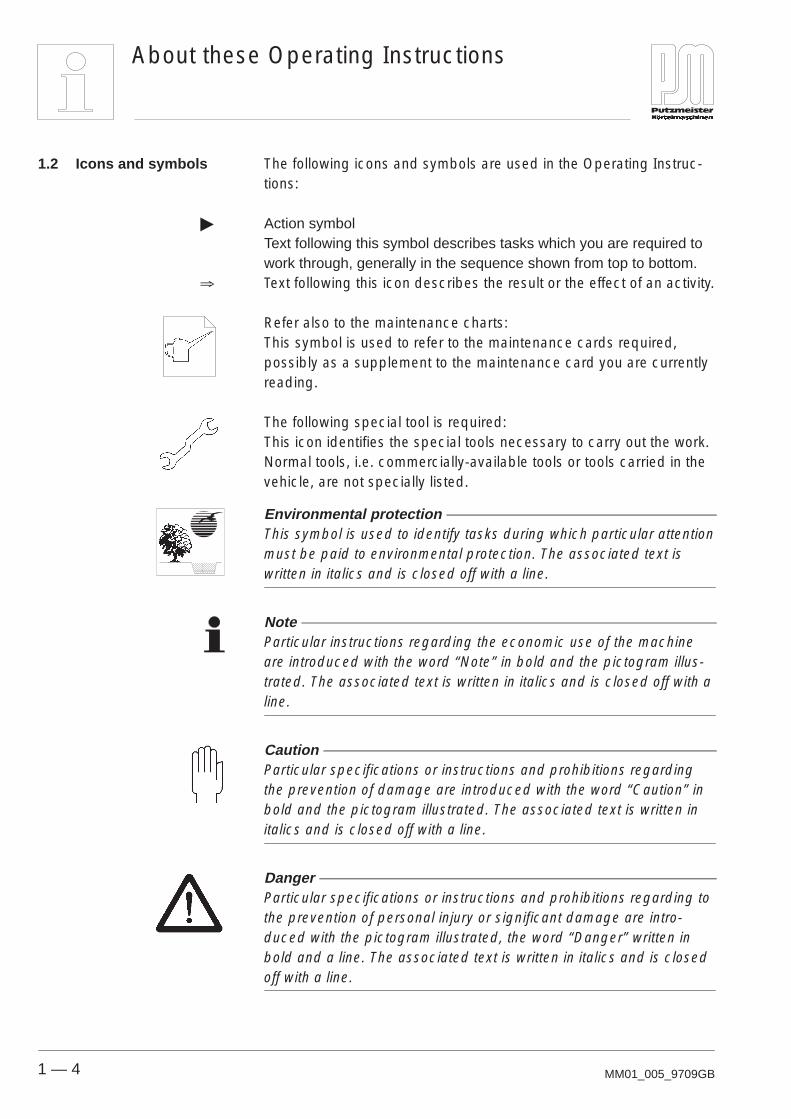
The following icons and symbols are used in the Operating Instruc-tions:
� Action symbolText following this symbol describes tasks which you are required towork through, generally in the sequence shown from top to bottom.
� Text following this icon describes the result or the effect of an activity.
Refer also to the maintenance charts:This symbol is used to refer to the maintenance cards required,possibly as a supplement to the maintenance card you are currentlyreading.
The following special tool is required:This icon identifies the special tools necessary to carry out the work.Normal tools, i.e. commercially-available tools or tools carried in thevehicle, are not specially listed.
Environmental protection This symbol is used to identify tasks during which particular attentionmust be paid to environmental protection. The associated text iswritten in italics and is closed off with a line.
Note Particular instructions regarding the economic use of the machineare introduced with the word “Note” in bold and the pictogram illus-trated. The associated text is written in italics and is closed off with aline.
Caution Particular specifications or instructions and prohibitions regardingthe prevention of damage are introduced with the word “Caution” inbold and the pictogram illustrated. The associated text is written initalics and is closed off with a line.
Danger Particular specifications or instructions and prohibitions regarding tothe prevention of personal injury or significant damage are intro-duced with the pictogram illustrated, the word “Danger” written inbold and a line. The associated text is written in italics and is closedoff with a line.
1.2 Icons and symbols

General Technical Description
2 — 1MM02_029_9802GB
2 General Technical Description
This section describes the components and assemblies on thismachine and describes how they function.
Below you will find an overview of the most important components;these will then be described on the following pages.
24000900
1
3 2
4 5
6
7 8
1 Rating plate2 Axle3 Auger pump4 Lifting unit5 Hopper6 Pressure connection7 Control panel8 Diesel engine
2.1 Overview
Lifting mixer

General Technical Description
2 — 2 MM02_029_9802GB
24001000
6 3 5 2
7 8
1
4
1 Rating plate2 Axle3 Auger pump4 Tipping mixer5 Hopper6 Pressure connection7 Control panel8 Diesel engine
Tipping mixer

General Technical Description
2 — 3MM02_029_9802GB
This chapter is intended to help you understand the functions of themachine so that you can limit the field of the machine’s applications tosuitable areas and avoid errors in operation.
Putzmeister machines are easy to assemble and operate. In spite ofthis, certain precautionary measures must be taken when operatingthe machine to ensure that the wear parts have as high a life limit aspossible.
The SP11 mortar spray pump is designed to process premixed drymortar and site mixes. It mixes, pumps and sprays continuously.
Dry mortar, water and concrete admixtures are mixed in the mixerand poured into the hopper. The mixed material is conveyed from thehopper by an auger pump.A spray gun is fitted to the end of the hose. Air is introduced from thecompressor and the mortar applied at the desired coat thickness.
The hydraulic fluid supply is sufficient to power several functionssimultaneously.The variable output auger pump, mixer and the mixer lifting unit aredriven by two separate hydraulic circuits.The mixer switches off automatically during the lifting process.
2.2 Description of thefunctions
General description ofthe machine
Hydraulic control
General Technical Description
2 — 4 MM02_029_9802GB
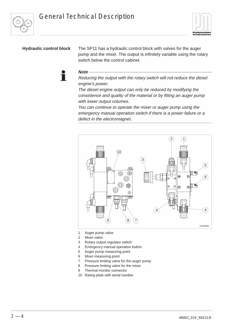
The SP11 has a hydraulic control block with valves for the augerpump and the mixer. The output is infinitely variable using the rotaryswitch below the control cabinet.
Note Reducing the output with the rotary switch will not reduce the dieselengine’s power.The diesel engine output can only be reduced by modifying theconsistence and quality of the material or by fitting an auger pumpwith lower output volumes.You can continue to operate the mixer or auger pump using theemergency manual operation switch if there is a power failure or adefect in the electromagnet.
24200600
12
3
5
6
4 4
789
10
1 Auger pump valve2 Mixer valve3 Rotary output regulator switch4 Emergency manual operation button5 Auger pump measuring point6 Mixer measuring point7 Pressure limiting valve for the auger pump8 Pressure limiting valve for the mixer9 Thermal monitor connector10 Rating plate with serial number
Hydraulic control block

General Technical Description
2 — 5MM02_029_9802GB
The SP11 is driven by a 3-cylinder diesel engine. A 4-cylinder dieselengine is also available on request.
The auger pump built into the machine is called a displacementpump. An auger (rotor) rotates inside a fixed auger barrel (stator).The auger consists of a highly wear-resistant, very hard metal alloyand the auger barrel of a multi-notched steel sleeve with vulcanizedelastic rubber core. The clamping sheath is used to reclamp theauger pump.
146003001 2
3
1 Auger2 Auger barrel3 Clamping sheath
The support legs on the frame are mechanically adjustable, thusgiving the stability required.
Support legs can be obtained from the tipping mixer if required.
24900100
1 1
1 Support legs
Auger pump
Support legs on thelifting mixer
General Technical Description
2 — 6 MM02_029_9802GB
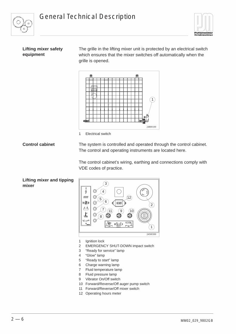
The grille in the lifting mixer unit is protected by an electrical switchwhich ensures that the mixer switches off automatically when thegrille is opened.
24800100
1
1 Electrical switch
The system is controlled and operated through the control cabinet.The control and operating instruments are located here.
The control cabinet’s wiring, earthing and connections comply withVDE codes of practice.
24500300
1
2
3
4
56
7
8
9 1011
12
1 Ignition lock2 EMERGENCY SHUT-DOWN impact switch3 “Ready for service” lamp4 “Glow” lamp5 “Ready to start” lamp6 Charge warning lamp7 Fluid temperature lamp8 Fluid pressure lamp9 Vibrator On/Off switch10 Forward/Reverse/Off auger pump switch11 Forward/Reverse/Off mixer switch12 Operating hours meter
Lifting mixer safetyequipment
Control cabinet
Lifting mixer and tippingmixer

General Technical Description
2 — 7MM02_029_9802GB
A 2-cylinder compressor has been integrated into the SP11 togenerate the air required to spray the mortar. This is driven by V-beltsfrom the diesel engine.
14300300
2-cylinder compressor
The air generated is transported through the air battery and an airhose to the spray gun. The spray air is also used to control the mortarpump pneumatically.
Caution Check the oil level on the inspection glass of the compressor daily.
Compressor

General Technical Description
2 — 8 MM02_029_9802GB
The technical data and properties given below apply for the SP11DMR and DMB.
Power unit: 3-cylinder diesel engine15.6 kW at 2800 rpm
Hopper: 220 l
Lifting mixer: 180 l
Tipping mixer:
Auger pump: 2L6 35 l/min, max 28 bar3L7 35 l/min, max 50 bar2L88 45 l/min, max 28 bar2L54 120 l/min, max 28 bar2L74 200 l/min, max 28 bar
DMR running gear: 1200 kg braked with support wheel
DMB running gear: 1000 kg unbraked without supportwheel
Axle: maximum 130 km/h
Nose loading: DMR 65 kg, DMB 30 kg
Compressor: 2 cylinder, 330 l/min
Max. delivery pressure: 40 bar
Max. particle size: 8 mm
Pumping rate: 10–40 l/min
DMR permitted gross weight: 1000 kg
DMB permitted gross weight: 750 kg
Noise level: < 85 dB(A)
DMR tyre size: 175–80 R 13
DMB tyre size: 165–80 R 13
Tyre pressure: 2.4 bar
Noise emission measurement on mortar machines gave a value of� 85 dB(A).
Measurement was carried out in accordance with the German”Maschinenlärm Informations Verordnung— 3. Verordnung zum Gerätesicherheitsgesetz —”(Maschine Noise Information Regulation — 3rd regulation relating to the German Equipment Safety Law —)
2.3 Technical data
Noise emissionmeasurement

General Technical Description
2 — 9MM02_029_9802GB
The most important data are shown in brief on the rating platemounted on the machine.
2
12
11
10
34
56
78
9
1
24001100
1 Model (machine model)2 Machine no. (machine number)3 Year of manufacture4 Maximum concrete pressure [bar]5 Maximum hydraulic pressure [bar] (max. fluid pressure in the hydraulic system)6 Voltage [V]7 Frequency [Hz]8 Power [kW]9 Sound level [dB(A)]10 Minimum support load [kg]11 Maximum support loading [kg]12 Permissible axle loading [kg]
Rating plate


Safety Regulations
3 — 1MM03_041_9802GB
3 Safety Regulations
This chapter summarizes the most important safety regulations. Thischapter is, therefore, particularly suitable for an initial basic instructionof new operators. Naturally, the various regulations are also repeatedonce more at the appropriate points in the Operating Instructions.
Note Special safety regulations may be necessary for some tasks. Thesespecial safety regulations will only be found in the description of theparticular task.
We include here a listing of regulations and safety standards for yourinformation:– EN 12001, Delivery, spraying and distributing machines for
concrete and mortar,– EN 292, Safety of machinery,– pr EN 12151,– EN 60204–1, Electrical equipment of machines,– EN 50081–1,– EN 50082–1,– EMC directives, 89/336/EEC,– Low voltage directives, 73/ 23/EEC,– Safety regulations for mortar delivery and spraying machines
issued by the German Industrial Employers’ Liability InsuranceAssociation ZH 1/575.

Safety Regulations
3 — 2 MM03_041_9802GB
Use the machine only in a technically perfect condition, as designatedand being conscious of safety and the dangers, taking account of theOperating Instructions. Any faults, especially those affecting thesafety of the machine, must, therefore, be rectified immediately.
Take care to ensure that:– no safety equipment is removed, rendered inoperable or modified
(EMERGENCY SHUT-DOWN button, grille on the pump fillinghopper etc.);
– safety equipment removed for the purposes of maintenance work isrefitted immediately the work is completed.
Check operational safety every time you start work. Any defectsfound or suspected must be repaired immediately. If necessary,inform the project supervisor. Cease work if defects that mayjeopardize operational safety are found.
Use only perfect delivery lines, hoses, couplings etc. suitable for thedelivery job and manufactured by the machine manufacturer. Deliverylines are subject to wear which varies according to the pressure andcomposition of the medium, the material from which the delivery lineis made, etc.
The machine is designed to mix and pump premixed dry mortarthrough 35/25 mm diameter hoses.You must also observe the specified Operating Instructions andcomply with the conditions and intervals for maintenance and inspec-tion to operate the machine within the limits of its designated use.
Use other than that above or going beyond such use, such transport-ing loads, for instance, is considered contrary to the designated use.Putzmeister Mörtelmaschinen accepts no liability for damage result-ing from such use. The risk of such misuse lies entirely with themachine operator.
We state here expressly that Putzmeister Mörtelmaschinen acceptsno liability for damage arising from incorrect or negligent operation,servicing or maintenance or as a result of use contrary to the desig-nated use. This statement is equally valid for modifications to, addi-tions to and customization of the machine which may compromisesafety. The guarantee will no longer be valid in such cases.
3.1 Principle
3.2 Designated use
3.3 Use contrary to thedesignated use
Exclusion of liability

Safety Regulations
3 — 3MM03_041_9802GB
High sound levels can cause permanent hearing damage.
However, 85 dB(A) may be exceeded in the vicinity of the machinedepending on operating conditions. A distance of less than 5 m fromthe machine is considered to be close.
Wear your personal ear defenders.
Instruct your personnel always to wear their personal ear defenders.As the operator, you are responsible for ensuring that your personnelcomply with this regulation.
Never reach into the moving parts of the machine, whether themachine is running or switched off. Always switch off at the mainswitch. Take note of the warning plate.
Never remove safety equipment or render it inoperable by modifyingthe machine.Safety equipment must only be repaired, adjusted or replaced bysubject experts.
In the event of malfunctions, stop the machine immediately and lockit. Have any faults rectified immediately.
All equipment required for safety and accident prevention (warningsigns and information notices, cover grilles, covers, etc.) shall be inplace. Such equipment may not be removed, modified or damaged.
Any safety devices removed for set-up, maintenance or repairpurposes must be refitted and checked immediately upon completionof the maintenance and repair work.
The place of work is the operating panel at the front of the machine.Do not climb on the machine.
3.4 Noise
Ear defenders
Operator
3.5 Sources of danger
Safety equipment
3.6 Place of work

Safety Regulations
3 — 4 MM03_041_9802GB
The machine may only be operated, maintained or serviced indepen-dently by persons (machine operators) who– are aged 18 years and older;– are physically capable (rested and not under the influence of
alcohol, drugs or medication);– have been instructed in the operation and maintenance of the
machine;– can be expected reliably to execute the tasks they are charged
with.
The machine must only be operated, serviced or maintained bypersons who are trained to carry out such tasks and have beencommissioned to do so.
Do not allow persons yet to complete training or instruction, orpersons taking a general training course, to operate the machineunless under the constant supervision of an experienced person.
Couplings must only be fitted to hoses by persons having thenecessary experience and possessing the equipment necessary forthis task.
Work on the electrical system and equipment of the machine must becarried out only by a qualified electrician or by instructed personsunder the supervision and guidance of a qualified electrician and inaccordance with electrical engineering rules and regulations.
Switch off the machine at the EMERGENCY SHUT-DOWN button inan emergency situation.
3.7 Selection andqualification ofpersonnel
Qualified electricians
3.8 Procedure in anemergency situation
Transport, Set–up and Connection
4 — 1MM04_018_9802GB
4 Transport, Set-up and Connection
In this chapter you will find information concerning safe transport ofthe machine. In addition to this, you will find descriptions of the workrequired to assemble and connect the machine. Starting the ma-chine will not be described until the “Operation” chapter.
In traffic, Putzmeister mortar machines are subject to German StZVO(Road Transport Licensing Order) regulations and may only bedriven on public highways if they are licensed accordingly.They must not be used for the transport of goods.
The machine is subject to the regulation which requires an individualregistration plate and also, therefore, a TÜV inspection (inspection toensure that vehicle is roadworthy) every two years. The registrationcan be obtained from the district authorities on production of the op-erating permission at the licensing office responsible. Outside Ger-many, the registration regulations applicable in the country of useshall always apply.
The running gear or vehicle complies with the regulations of theGerman StZVO (Road Transport Licensing Order) and is licensed inGermany for speeds up to a maximum of 80 km/h.
For countries where transport speeds of over 80 km/h are permiss-ible (eg 130 km/h in France), special written approval must be ob-tained from Putzmeister. If you do not have this written approval youmay only drive Putzmeister vehicles at speeds up to 80 km/h, even inthose countries which permit speeds exceeding 80 km/h.
The maximum permissible speed shall apply in countries wherepermissible speeds are less than 80 km/h maximum.
Information relating to maximum speeds may be found in the reportprepared in accordance with article 18 (5) of the German StZVO(Road Transport Licensing Order).
4.1 Before moving off

Transport, Set–up and Connection
4 — 2 MM04_018_9802GB
Maximum speeds of below 80 km/h for trailers must be noted underFigure 33 : Notes.
The machines are certified for roadworthiness in Germany. You willreceive the operating permission upon delivery. The registrationregulations applicable in the country of use shall always apply.
You may have to obtain an additional country-specific licencedepending on the country of use and the relevant regulations.The operating permission must be carried with the machine duringtransport at all times and must be produced upon request from thepolice.
Before you join the public highway, you must carry out the followingactions:
� Check that the vehicle is safe to drive. The lighting systemmust be fully functional and well secured.
� Check the brakes, tyre inflation pressures, etc.
� Check whether the support leg and the support wheel aresecured for travel.
� Check that the accessories are secure.
� Observe the permissible gross laden weight.
Note The trailer-mounted machine is subject to the regulation whichrequires an individual registration plate (green) and also, therefore, aTÜV inspection every two years. The registration can be obtainedfrom the district authorities on production of the operating permissionat the licensing office responsible. Outside Germany, the registrationregulations applicable in the country of use shall always apply.
The chocks for securing the machine against rolling away areattached to the side of the frame.
Chocks
Transport, Set–up and Connection
4 — 3MM04_018_9802GB
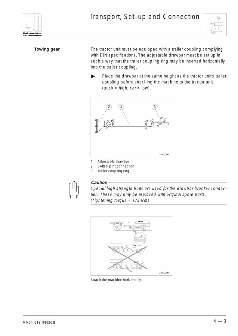
The tractor unit must be equipped with a trailer coupling complyingwith DIN specifications. The adjustable drawbar must be set up insuch a way that the trailer coupling ring may be inserted horizontallyinto the trailer coupling.
� Place the drawbar at the same height as the tractor unit’s trailercoupling before attaching the machine to the tractor unit(truck = high, car = low).
24900200
1 32
1 Adjustable drawbar2 Bolted joint connection3 Trailer coupling ring
Caution Special high strength bolts are used for the drawbar bracket connec-tion. These may only be replaced with original spare parts.(Tightening torque = 125 Nm)
24001200
Attach the machine horizontally.
Towing gear
Transport, Set–up and Connection
4 — 4 MM04_018_9802GB
Please note the following before you transport the machine:
Note Mortar machines are considered to be industrial machines. Your ma-chine requires an operating permission in accordance with article18, paragraph 2 of the German StZVO (Road Transport LicensingOrder). It requires its own licence number. For this reason, you arerequired to produce the General operating permission certificate youwere given to the licensing office responsible. Only then may yourmachine be transported behind an appropriate tractor unit on publichighways.
� Please ensure that the trailer hitch is functioning correctly.
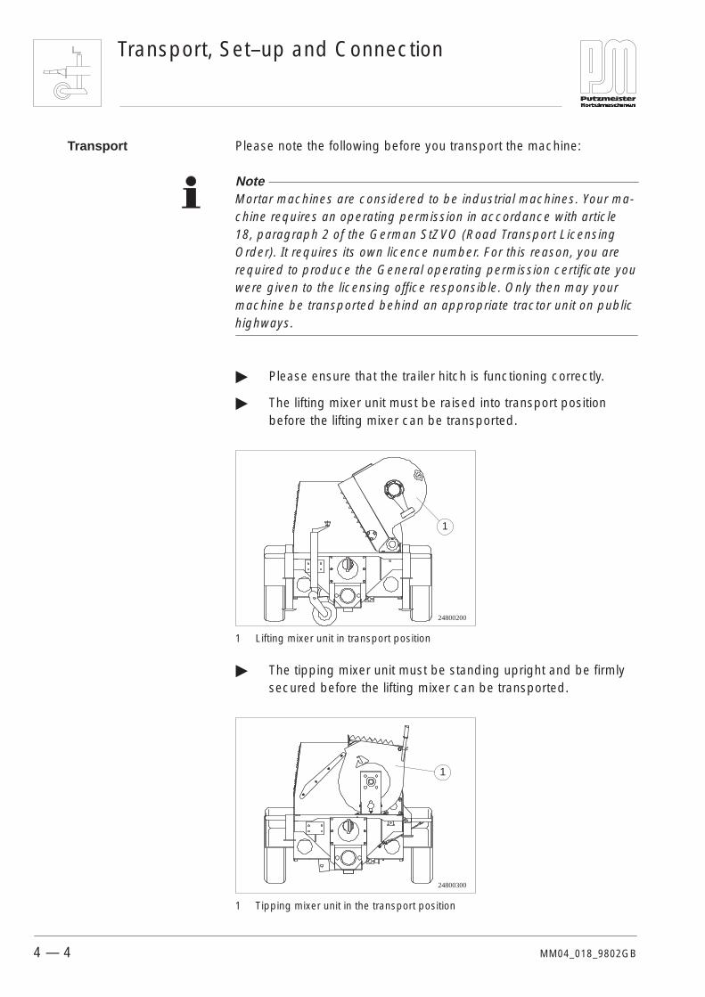
� The lifting mixer unit must be raised into transport positionbefore the lifting mixer can be transported.
24800200
1
1 Lifting mixer unit in transport position
� The tipping mixer unit must be standing upright and be firmlysecured before the lifting mixer can be transported.
24800300
1
1 Tipping mixer unit in the transport position
Transport

Transport, Set–up and Connection
4 — 5MM04_018_9802GB
� Please ensure that the lighting equipment is functioningcorrectly and is secured.
� Observe the permitted towed load for the tractor unit.
� Additional loads on the machine are not permitted. Observethe maximum gross weight on the rating plate.
Caution Since the support wheels of braked machines fold away automati-cally when cranked down, the machines could slump and damagethe tractor unit.
You can also load your machine onto a suitable transport vehicle totransport it to the construction site.
Caution The machine may only be loaded by crane if it is attached by the lift-ing eyes designed for this purpose. Lifting equipment, lifting tackle,support trestles and other auxiliary equipment must be reliable andsafe in operation. Make sure that the loadbearing capacity isadequate.
The machine must be properly secured on the transport vehicle toprevent it rolling away, slipping or tipping over.
Danger Hoisted loads may fall if they are not loaded properly or if the slingsand eyes are damaged.You should, therefore, never walk under suspended loads.
The machine may only be transported once secured to a suitabletransport vehicle.
4.2 Loading
Transport, Set–up and Connection
4 — 6 MM04_018_9802GB
The responsibility for setting up the machine safely falls on theoperator.Inspect the proposed site carefully and reject the set-up site if youhave any doubts in respect of safety.
The set-up site must:– be large enough to ensure that there is sufficient clearance around
the whole machine;– ensure the accessibility of the machine from all sides for the
purposes of servicing and repair.
Make sure that the machine is standing as horizontally as possible toensure the supply of fluid and lubrication.
The machine’s operations site should be selected in such a way that:– no sharp pipe and hose bends are required;– no hoses overlie one another.
Risk of chafing;– the lines are kept as short as possible.
The diesel engine receives its fresh air from above the lightingequipment. Please ensure that the end of the machine is not locateddirectly above a pile of sand or a particularly dusty area. Make surethat empty mortar sacks are not placed over the intake area. Pleasecover the ground with wooden boards or cardboard if you cannotavoid doing this. This is the only way to prevent the machine or airfilter being contaminated.
4.3 Set-up site
Requirements on theset-up site
Setting up
Operations site

Machine Operation
5 — 1MM05_018_9802GB
5 Operation
In this chapter you will find information on the operation of themachine. You will learn what operations are required for setting upthe machine, in operation and for cleaning.

Machine Operation
5 — 2 MM05_018_9802GB
Make sure you are completely familiar with the procedures forshutting down the machine in an emergency situation before you startoperating the machine.
Danger Proceed immediately as described below if an emergency occurswhile you are operating the machine.
34500500
Press to lock EMERGENCY SHUT-DOWN
Turn to unlock EMERGENCY SHUT-DOWN
� Press the EMERGENCY SHUT-DOWN button.� The pump must come to a halt immediately.
� Take emergency measures, where necessary.
� Note the incident and report in accordance with companyprocedures.
� Look for the cause of the fault and rectify it completely.Start up the machine in accordance with the rules for starting upthe machine.
� Unlock the EMERGENCY SHUT-DOWN button by turning it.
Caution The machine is no longer safe to operate if the EMERGENCYSHUT-DOWN button is defective, as you will no longer be able toswitch off the machine quickly enough if danger threatens.
5.1 Shutting down in anemergency situation
EMERGENCY SHUT-DOWN button on thecontrol panel

Machine Operation
5 — 3MM05_018_9802GB
Today, premixed dry mortars are produced in such a way that theymay be easily processed by mortar machines. Please also observethe advice of the material manufacturers.
Site mixes, however, are subject to particular laws which must beadhered to at all times.
While mortar for manual application needs only to be prepared tohave good cured mortar characteristics and workability, mortarproduced with mortar machines also has to be easy to pump andspray.
Although mortar which is too fat or sticky does not usually tend tocause blockages and separation, it will still cause high pump pres-sure. On the other hand, mortar which is too lean or short causes lowdelivery pressure which can easily cause separation and blockages inthe pump or hose.
Pumping mortar must be ductile, ie not to thick or thin. Mixtures whichare too thin tend to allow the sand to settle and cause blockages.Mixtures which are too stiff cannot be sucked in.
Mortar pumps pump what is known as “trowel-quality consistence”mortar best.
You can improve mortar consistence and quality, save water andimprove the pumping ability of the mortar with the use of certainadditives.
5.2 The correct mortarmixture
Consistence
Machine Operation
5 — 4 MM05_018_9802GB
The type of sand (grading curve) and the type of sand grain bothdetermine render quality and have a strong influence on the pumpingcharacteristics of the mortar produced from it.
Good grading curves are important. The sand must contain coarse,medium and fine grains and should also possess so-called “consum-able” constituents. “Single grain sand” types, as they are known, inwhich the proportion of a single grain size group is excessive are notconducive to pumping, although their use is often unavoidable. It isimportant, in such an event, to mix different types of sand to obtain asatisfactory grain grading.
Well-graded sand grains with grain sizes up to 4 mm are easier topump than fine beach sand (single grain sand).
In general, grain size must not exceed 4 mm.
A good grain combination for plastering sand is as follows:
Grain size below 0.2 mm = 5%
Grain size from 0.2 – 1.0 mm = 60%
Grain size from 1.0 – 4.0 mm = 35%
The choice of binder depends on the intended application of themortar. The following points are of significance in obtaining goodpumping characteristics:
Slaked lime always produces grainy and firm, non-segregated mortar.It has proved to be extremely useful for blockages and in particularfor sand types which do not pump well. It is generally useful to addlime to improve the pumping characteristics of the mortar.
Pure cement mortar must be regarded as dangerous. In this case,you should obtain a pumpable mixture by including additives in themix.
Mortar sand
Binder

Machine Operation
5 — 5MM05_018_9802GB
Take extra care when choosing an additive from the extensive rangewhich is available. We are only able to give general guidelines whichrelate to chemical additives, eg:
It has always proved to be useful to add a concrete liquifier withoutair-entraining agents and this also saves on water and improves thequality of the mixture (please contact local representatives or buildingmaterials suppliers for more information).
The following materials have also proved to be useful in practice foravoiding blockages in the case of sharp mortar:
Stone dust, fly ash etc.
If you are unsure of which mixture to use, please contact ourspecialist staff who will be pleased to prepare it for you. Please alsobear in mind that we can only make recommendations for mixtures.The user is responsible for the quality and workability of a particularmortar.
The following are our non-binding recommendations for commonmortar compositions:
This can be used to plaster pedestals, concrete elements etc. It iscomposed of river sand and cement.Mix ratios:approx. 1 quantity (by volume) of cement, 2 of river sand (0–4 mm)and additive.
This is used to plaster brickwork.
Mix ratios:Different mixtures are possible in this case, depending on the region,method of operation and the available materials:1 quantity (by volume) of slaked lime, 4 of river sand (0–4 mm)without the addition of mortar additiveor1 quantity (by volume) of hydraulic powder chalk, 2 of river sand, 1 ofpit sand (the sand quantities could be reversed if required, dependingon the sand typeor1 quantity (by volume) of cement, 0–5 of chalk, 3 of river sand, 1 ofquarry sand (possibly with additives or air-entraining agents).
Additives
Site mixes
Cement mortar
Basic plastering mortar

Machine Operation
5 — 6 MM05_018_9802GB
When you accept the machines, you must make yourself so familiarwith the equipment that damage and accidents cannot occur.Every time you use the machine, you accept full responsibility for thesafety of anyone located in the machine’s danger zone. You aretherefore obliged to ensure the absolute operational safety of theequipment.
10000700
Oil and fuel levels
Danger Oils, fuel and other functional fluids may be injurious to health oncontact with the skin etc.You must, therefore, always wear personal protective clothing andequipment when you are handling toxic, caustic or other functionalfluids that are injurious to health and and always take note of themanufacturer’s information.Avoid naked flames near the machine and close the fuel tank when ithas been topped up – risk of fire.
Note The machine must be level when you check the functional fluids.
5.3 Starting up
Functional fluids

Machine Operation
5 — 7MM05_018_9802GB
24300100
1
2
1 Hydraulic fluid level2 Fuel tank
� Check the fuel level on the transparent hose located at the frontend of the fuel tank.
� Check the hydraulic fluid level on the transparent hose on thehydraulic fluid reservoir.
24300200
1
2
1 Transparent hose2 Hydraulic fluid reservoir
Machine Operation
5 — 8 MM05_018_9802GB
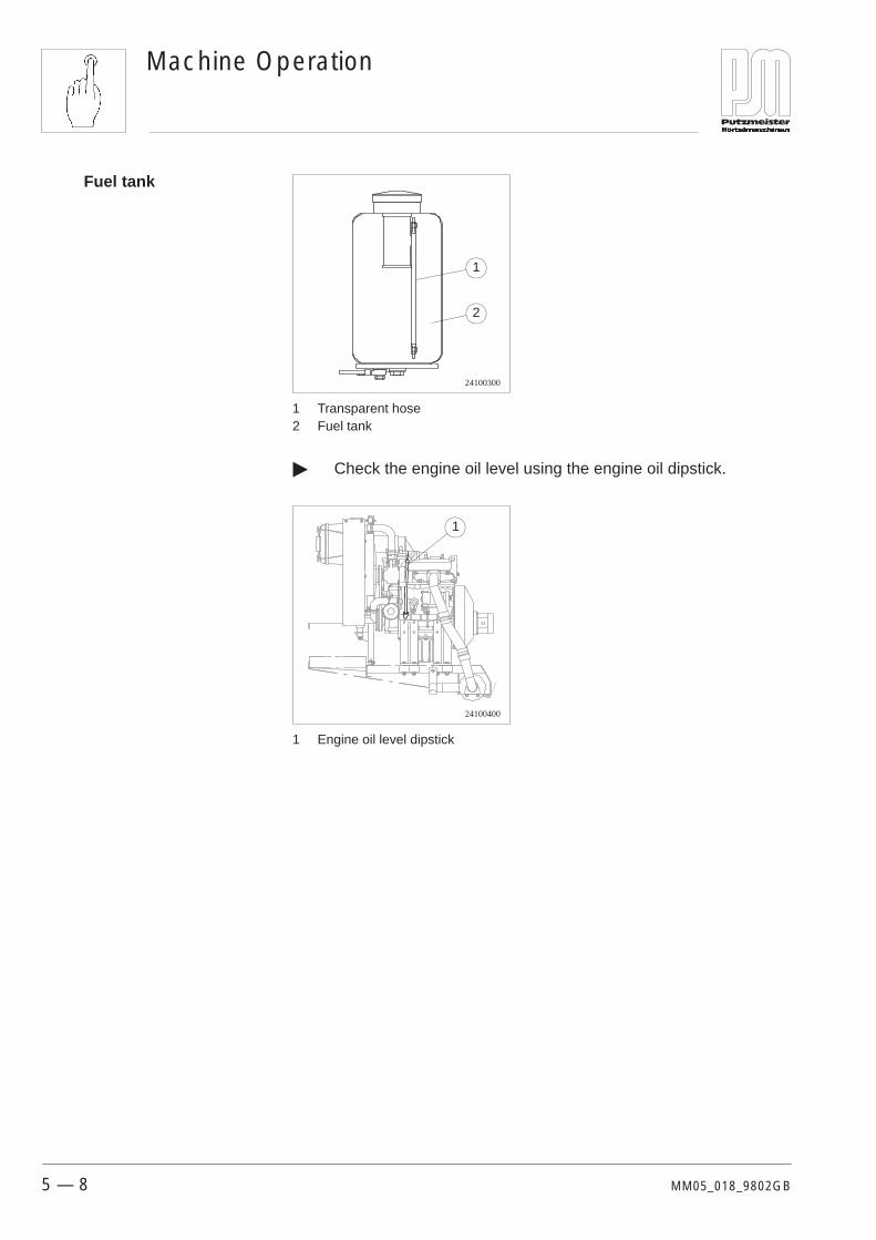
24100300
1
2
1 Transparent hose2 Fuel tank
� Check the engine oil level using the engine oil dipstick.
24100400
1
1 Engine oil level dipstick
Fuel tank

Machine Operation
5 — 9MM05_018_9802GB
The starting up procedure is the same for a diesel car. The procedureis as follows:
� Shift the throttle lever to full throttle and open the air tap on thespray gun. The toggle switch for the agitator and the mixer mustbe set to 0 so that the diesel engine can start up on no-load.
34100100
1
1 Throttle lever
� Close the cover and lock it.
� Now turn the ignition key to the right to position 1. The Readymode lamp will light up.
� Now turn the ignition key further to the right to position 2. TheGlow lamp will light up and the preglow procedure begins. TheReady to start lamp will light up after approximately 9 seconds.Now start up the engine by turning the ignition key to the right.
Caution Do not allow the engine to preheat for longer than is necessary(20 seconds maximum) or the glow plugs and starter solenoid couldbe damaged! Preheat the engine even when ambient temperatures are high.
� Now turn the throttle fully to the left. The engine is now runningat idling speed.
Starting up

Machine Operation
5 — 10 MM05_018_9802GB
Carefully carry out the operations for starting up the machine andsetting up the machine and ensure that it is functioning perfectlybefore you fill the hopper with medium and begin pumping it throughthe delivery line.
Note Should a malfunction occur when the pump is in operation, firstconsult the “Quick Troubleshooting Guide” chapter in these operatinginstructions. Call on the Putzmeister After Sales department if you areunable to rectify the fault yourself.
Pumping must generally be started with the aid of a cement grout.
Before you prepare the grout for lubricating the delivery line, youmust check the mixer shaft and lifting device bearings to see if theyare properly lubricated. Also, be sure to check the seals on the hosecouplings.
Rinse the delivery line out briefly with water before connecting it. Useone or two of the sponge balls provided as standard accessoriessoaked in water to do this.
Now mix in thin cement grout (approximately 20 litres) and add this tothe hopper.
Check the putput regulator to ensure that the rotary knob is turnedcompletely to the right, ie is set at a very low level.
14400500
1
1 Rotary knob for the output regulator
5.4 Operation
Mixing and starting topump

Machine Operation
5 — 11MM05_018_9802GB
You may set the throttle lever to full power if this is the case.
34100100
1
1 Throttle lever
Now switch the auger pump on at the switch on the control cabinet.
24500301
1
1 Pump on switch

Machine Operation
5 — 12 MM05_018_9802GB
You may now start pumping by turning the output regulator slowly tothe left.
14400500
1
1 Turn the output regulator knob to the left
Caution Make sure that you are completely familiar with the procedure forshutting down the system in the event of an emergency before youbegin pumping operations.You may change only the rate of output using the output regulator.This doe not change the load on the diesel engine. Reducing the out-put will not improve the situation if the auger pump stops as the resultof overloading. This will only be achieved if you reduce the load onthe mortar pump (reduced hose length and larger hose diameter).The ideal pumping pressure is < 20 bar.
Machine Operation
5 — 13MM05_018_9802GB
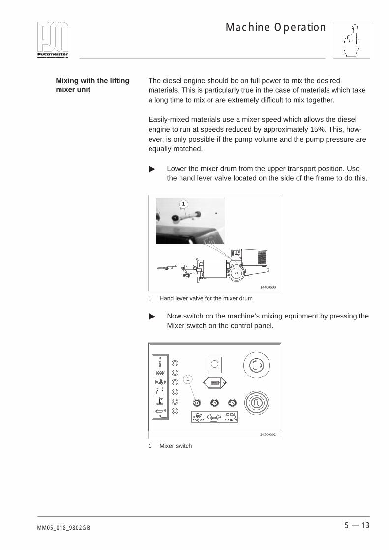
The diesel engine should be on full power to mix the desiredmaterials. This is particularly true in the case of materials which takea long time to mix or are extremely difficult to mix together.
Easily-mixed materials use a mixer speed which allows the dieselengine to run at speeds reduced by approximately 15%. This, how-ever, is only possible if the pump volume and the pump pressure areequally matched.
� Lower the mixer drum from the upper transport position. Usethe hand lever valve located on the side of the frame to do this.
14400600
1
1 Hand lever valve for the mixer drum
� Now switch on the machine’s mixing equipment by pressing theMixer switch on the control panel.
24500302
1
1 Mixer switch
Mixing with the liftingmixer unit
Machine Operation
5 — 14 MM05_018_9802GB
� Now mix the first mortar mixture in the mixer drum.
Note First add water, then binder, then sand. Mix the first mortar mixtureslightly fatter than normal. The mixture should be of trowel-quality.
Now empty the mixer drum into the hopper. Pump slowly until thematerial reaches the spray gun. You may now set the desired deliveryrate.
Caution The mixer will switch off automatically during the lifting process.
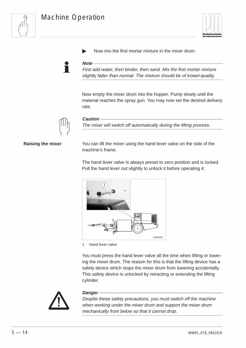
You can lift the mixer using the hand lever valve on the side of themachine’s frame.
The hand lever valve is always preset to zero position and is locked.Pull the hand lever out slightly to unlock it before operating it.
14400600
1
1 Hand lever valve
You must press the hand lever valve all the time when lifting or lower-ing the mixer drum. The reason for this is that the lifting device has asafety device which stops the mixer drum from lowering accidentally.This safety device is unlocked by retracting or extending the liftingcylinder.
Danger Despite these safety precautions, you must switch off the machinewhen working under the mixer drum and support the mixer drummechanically from below so that it cannot drop.
Raising the mixer
Machine Operation
5 — 15MM05_018_9802GB
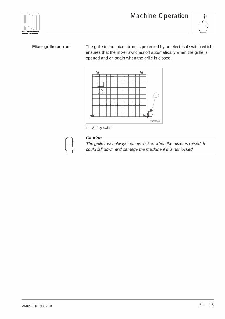
The grille in the mixer drum is protected by an electrical switch whichensures that the mixer switches off automatically when the grille isopened and on again when the grille is closed.
24800100
1
1 Safety switch
Caution The grille must always remain locked when the mixer is raised. Itcould fall down and damage the machine if it is not locked.
Mixer grille cut-out
Machine Operation
5 — 16 MM05_018_9802GB
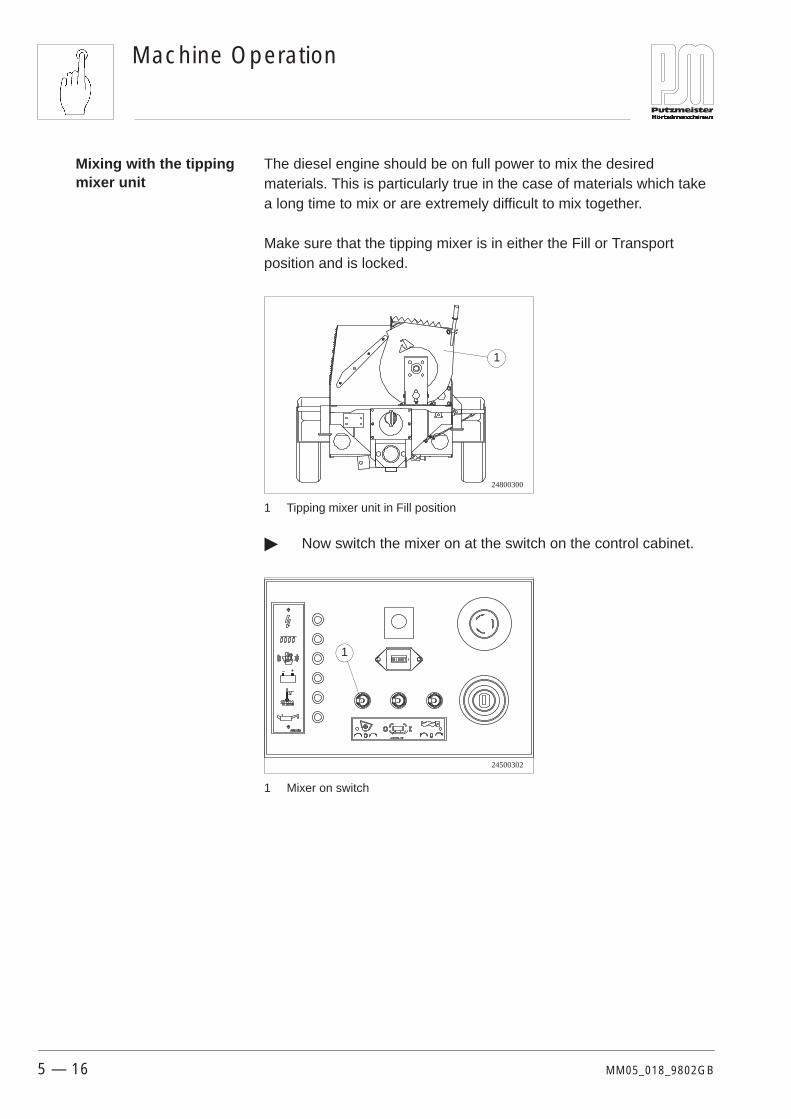
The diesel engine should be on full power to mix the desiredmaterials. This is particularly true in the case of materials which takea long time to mix or are extremely difficult to mix together.
Make sure that the tipping mixer is in either the Fill or Transportposition and is locked.
24800300
1
1 Tipping mixer unit in Fill position
� Now switch the mixer on at the switch on the control cabinet.
24500302
1
1 Mixer on switch
Mixing with the tippingmixer unit

Machine Operation
5 — 17MM05_018_9802GB
� Now hold the slewing mixer unit firmly by the handle andrelease the lock. To do this, push the locking handle on thespherical head upwards.
24800400
1
1 Locking handle
� Now rotate the mixer to the left in the direction of the hopper.The grille opens automatically and the mixer switches off. Themixer can now empty into the hopper and is automaticallylocked into the empty position once more.
The grille opens and the mixer switches off automatically whenthe mixer is rotated to the empty position.
� Tip back to the Fill position once the tipping mixer unit hasemptied. To do this, you must first lift the locking lever.

Machine Operation
5 — 18 MM05_018_9802GB
Once the pump is pumping you must empty the advance cementgrout from the end of the delivery line, ie the spray gun, into a con-tainer. You may commence spraying as soon as the mortar appears.
Guide the spray gun in smooth movements as close to the wall aspossible. The ideal distance is around 20 cm. If possible, direct themortar jet slightly upwards to cut mortar loss to a minimum.
15100200
Guide the spray gun back and forth in smooth movements
You can interrupt the delivery process from the spray gun. Close thecontrol tap on the air line. The pump will shut down after a short time.You can stop the flow of material immediately on a spray gun withisolator valve.
15100300
1
1 Control tap on the air line.2 Isolator valve on the material line
Switch off the machine during longer breaks. The agitator can also beswitched off if you wish to continue mixing, thus avoiding segregationof critical materials.
Mortar spraying
Interruption in work

Machine Operation
5 — 19MM05_018_9802GB
Remote air control via the spraying apparatus is provided as standardequipment for pump control.
The air is pumped into the air battery from the compressor. Fromhere, the air travels via a hose to the front of the machine. This iswhere the check valve and the double compressed air cock arelocated.
24200700
1
23
4
1 Double compressed air cock2 Check valve3 Pressure-relief valve4 Pressure switch
5.5 Pump control

Machine Operation
5 — 20 MM05_018_9802GB
The diesel engine has an electrical cut-out. It has one generator(18 ampere) and has an engine monitoring system.
This means that:
� Power is supplied by a 12 V, 70 Ah car battery.
� The diesel engine switches off automatically if the oil pressuredrops or the cooling water overheats.
� The charge warning lamp lights up if the generator fails. Theengine will not, however, switch off.
� The diesel engine runs at a speed of 2800 rpm under load anddevelops 15.6 KW of power.
� The 20 litre fuel tank is located behind the engine. The fuel issupplied via a fuel filter, a main fuel filter and the electrical fuelpump.
� You can get information on the diesel engine’s performancefrom the operating hours meter on the control panel.
Controls and cut-outs in thediesel engine

Machine Operation
5 — 21MM05_018_9802GB
Only use original Putzmeister hoses which meet prescribed operatingand burst pressures.
Note Only Putzmeister couplings and fittings are guaranteed to complywith the values specified in the German ”Unfallverhütungsvorschrift”(Accident Prevention Regulation).
You must secure hoses with threaded spouts by gluing. You mustensure that you use a seal which is designed for the purpose tosecure any new coupling against being opened. You must screw thecoupling to the stop. After this, it should no longer be possible to undoit by hand.
Use 50 mm internal diameter hoses. We recommend the use of a35 mm internal diameter end hose.
Caution Only couple hose couplings which have been cleaned and have goodcondition. Soiled couplings are not properly sealed and allow water toleak out under pressure. This leads inevitably to blockages.
Well-graded sand with grain sizes up to 4 mm are easier to pumpthan fine beach sand (single grain sand).
In general, grain size must not exceed 4 mm.
A good grain composition for plastering sand is as follows:
Grain size below 0.2 mm = 5%
Grain size from 0.2 – 1.0 mm = 60%
Grain size from 1.0 – 4.0 mm = 35%
The choice of binder depends on the intended application the mortar.The following points are of significance in obtaining good pumpingcharacteristics:
5.6 The mortar line
Binder

Machine Operation
5 — 22 MM05_018_9802GB
The machine and the delivery hose should be cleaned in the followingsequence when the work is completed.
If required, a high-pressure water pump is available for the purpose.
25200100
High-pressure water pump
Clean the machine first, then the delivery line.
� Pump the hopper out and switch off the diesel engine.
� Allow the machine to pump in reverse for a short time anddisconnect the delivery line.
Danger Before you disconnect the delivery line, check on the pressure gaugeto ensure that the system is fully depressurized. You must wearprotective goggles.Turn your face away when opening the line coupling.
� Now wash the machine clean with water. Rinse out the hopperand mixer drum until it is clean.
� Now pump water from the hopper through the pump until thewater begins to exit the the pressure connection cleanly oncemore. The machine is now fully cleaned out.
� Drain the leavings at the drainage connection and rinse thehopper out once more with water.
� Now clean the delivery line.
5.7 Cleaning
Machine

Machine Operation
5 — 23MM05_018_9802GB
Use the sponge balls provided in the accessories to clean thedelivery line.
Danger You clean the delivery line with compressed air at your own risk.Putzmeister accepts no liability for damage caused by compressedair cleaning.
Note You will avoid wear on the auger pump if you use a water pump toclean the delivery line.
� Push a water-soaked sponge ball into the delivery line. Recon-nect this to the machine. Then pump water from the hopper intothe line so that the sponge balls and leavings are pushedforwards. Repeat this procedure until the delivery line is clean.
15000300
1
2
1 Sponge ball2 Delivery hose
Caution You should empty any residual water out of the delivery line to avoidthe risk of the delivery line bursting.
Delivery line

Machine Operation
5 — 24 MM05_018_9802GB
Clean all seals and the seal seats. Grease the seals before re-assembling them. Soiled couplings are not sealed and necessarilylead to blockages.
14700101
1
2
1 Pressure connection2 Rubber seal
Clean the air cock and air nozzle tube on the spray gun.
15100101
2
1
1 Air cock2 Air nozzle tube
Caution The machine and lines must be drained fully of residual water if thereis a risk of freezing.
Note A frequent error committed when cleaning out the delivery lines is forwater to be pumped through the delivery line before a sponge ballhas been inserted. This later leads to blockages in the delivery linesince residual sand remains in the hose.
Spray gun

Machine Operation
5 — 25MM05_018_9802GB
Switch off the diesel engine and spray the radiator inside and out witha water jet.
Caution Do not use diesel fuel for cleaning purposes. Diesel fuel attacksrubber parts and encourages dust deposits in the radiator fins.
14400700
Spray the radiator down with a water jet
Caution Do not use high-pressure cleaning apparatus. The fins in the radiatorcould be bent by the high pressure jet.
Note Use a water hose with the correct nozzle to clean the radiator. A linepressure of 4 bar is sufficient for this purpose.
You may use a paint brush or soft brush in addition to the water jet ifthe dirt is difficult to shift.
Please also ensure that the radiator fins are not damaged while doingthis.
Diesel engine radiator
Machine Operation
5 — 26 MM05_018_9802GB
Blockages can occur inside the pump itself as well as in the deliveryline. You can recognise this by the pump not delivering while thepressure on the pressure gauge increases. The engine stalls in theevent of a blockage inside the pump.
Blockages can be avoided. However, they do still occur from time totime:– as a result of insufficient lubrication of the delivery line,– as a result of mortar which is hard to pump and segregates easily,– as a result of leaks in the delivery line couplings.
Rectify blockages as follows:
� Pump in reverse for a short time to decrease the pressure in thedelivery line.
� Switch off the diesel engine.
� Uncouple the delivery line and clear the blockages in the line byshaking and tapping it.
� Rinse the line out with water if neccesary.
� When you start the engine up again, add a cement grout to thedelivery line.
Danger You should only uncouple the delivery line when you have checkedon the pressure gauge that the system is fully depressurized.
5.8 Blockages – causes/remedies
Rectifying blockages

Quick Fault Assistance
6 — 1MM06_008_9802GB
6 Quick Fault Assistance
This chapter gives you a summary of faults and their possible causes,and also ways in which you may rectify them.
This chapter describes the possible causes of defects which mayaffect the SP11 and how to rectify them.
The diesel engine will not start.
Cause Remedy
No starting sound is audible orthe starter is only rotating veryslowly.
Check whether the battery still has a voltage. The switches for the auger pump and the mixer must be in thezero position.
The starter is turning quickly, but the engine is still not starting.
Cause Remedy
Too little fuel in the tank.Defective glow plugs. The fuel pump is defective.
Check whether there is sufficient fuel in the tank. Check on thediesel engine to see if the release magnet mounted on the fuelinjection pump is switching. If it is not, please contact your specia-list workshop.
6.1 SP11 in general

Quick Fault Assistance
6 — 2 MM06_008_9802GB
The diesel engine switches itself off during operation.
Cause Remedy
Lack of fuel, lack of oil, lack ofcooling water, thermal over-load.
Top up with fuel. Check the fuel lines for kinks and leaks. Checkthe engine oil level and top up with oil if necessary. Top up thecooling water. Check the cooling apparatus for contamination orforeign bodies.
Danger Allow the diesel engine and cooling apparatus to cool down beforetopping up the cooling water. Risk of scalding.
The diesel engine is not performing to full capacity, is emitting large amounts of soot and isstalling.
Cause Remedy
The air filter is contaminated. Replace the air filter cartridge.
The mixing unit in the mixer drum is not working.
Cause Remedy
The grille on the mixer is openor the safety switch is defec-tive.
Close the grille on the mixer drum and check the rotary switch.
The mixer is jammed (mixturetoo dry or stone chippings).
Switch the mixer drive switch on the switchboard to reverse drive,keep your finger on the switch and add water. Repeat this processuntil the mixer is running freely again. The machine must be shutdown and the mixer drum cleared if this is not successful. Pleasecontact your specialist workshop if the cleared mixer still does notrotate when the grille is closed.

Quick Fault Assistance
6 — 3MM06_008_9802GB
The machine will not start up despite the compressor being switched on.
Cause Remedy
A blocked air nozzle tube in thespraying device causing aninsufficient drop in pressure inthe remote control.
Clean the air nozzle tube and the air line.
The mortar is discharging alternately thick and thin.
Cause Remedy
The lack of water causes themortar to thicken too much,thus increasing the pressureand reducing the delivery rate.The uniform addition of waterresults in the liquification of thematerial. This fault may be thefirst indication that the augerparts are worn.
Re-tighten or replace the auger parts.

Quick Fault Assistance
6 — 4 MM06_008_9802GB
Interrupted mortar flow.
Cause Remedy
The material is reaching theend of the hose irregularly andis spraying with force.
Check whether the hopper is nearly empty thus allowing air to besucked in. For this reason, always ensure that there is sufficientmaterial in the hopper.
The flow of material is beingconstantly interrupted withoutspraying.
Check whether the air tap on the spray gun is completely open.
Check whether the delivery line is forming a loop or is kinked.
Check on the spray gun to see if the air nozzle pipe is clear. Itmust be cleaned with the spike included in the accessories if thisis the case.
No air in the spray gun.
Cause Remedy
The pump is operating andmaterial is arriving in the spraygun. However, there is onlyvery limited air or no spray airat all.
Check whether the rubber seals are present on the delivery linecouplings and ensure that the connections are tight.
Check whether the delivery line is leaking or broken.
Check whether the V-belt on the diesel engine to the compressoris broken.
Check whether the air hose from the compressor to the air batteryis leaking.
Maintenance
7 — 1MM07_018_9802GB
7 Maintenance
In this chapter you will find information on the maintenance worknecessary for the safe and efficient operation of the machine.
Following the general maintenance information, you will find themaintenance charts necessary for this machine. A summary of themaintenance charts listed by number is included in the table ofcontents.
We should like here to emphasize expressly that all prescribedchecks, inspections and preventative maintenance work must be con-scientiously carried out. Otherwise we will refuse any liability orwarranty claim. Our After Sales department is available to you withadvice and help at any time should you be in doubt.
The following table shows the intervals for the various maintenancetasks. The associated maintenance charts can be found further on inthis chapter.
Note Have the initial after-sales service carried out after the first 100 oper-ating hours by a Putzmeister Mörtelmaschinen GmbH After Salesservice engineer, or by a dealer authorized by Putzmeister Mörtel-maschinen GmbH. The machine operator responsible for themachine should be present for this service.
7.1 Maintenance intervals

Maintenance
7 — 2 MM07_018_9802GB
Assembly Action daily weekly annually asrequired other intervals
General Visual and function check on allsafety equipment � 40–001
Check threaded unions againsttightening torque table � —
Visual inspection of electricalcabling � 40–001
Check all wear parts � —
Check delivery line andcouplings � —
Hydraulicsystem
Have the hydraulic componentsinspected by an authorizedinspector from PutzmeisterMörtelmaschinen GmbH
� —
Check hydraulic fluid level �
Change the hydraulic fluid after 500 opera-ting hours
44–005
Change the hydraulic fluid filter �at initial after-sales service
44–003
Transmission Change transmission oil every 3 years —
Check mixer bearings fortightness � —
Auger pump Auger wear check � 46–003
Pressureconnection
Pressure connection wear check �after 500 opera-
ting hours—
Hopper Grease agitator bearings � —
Check agitator cut-out � —
Running gear Check tyre pressures before eachjourney
—
Check brake function before eachjourney
—
Adjust overrunning brake � 49–001
Grease overrunning brakeequipment and axle �
after approx.500 km
40–003
Check wheel nuts
after the first50 km or 50 km
after everywheel change
—
Check the play in the wheelbearings and adjust if required
after the first100 km
every 500 km—
Grease wheel bearings after approx.13000 km
—

Maintenance
7 — 3MM07_018_9802GB
Assembly other intervalsasrequiredannuallyweeklydailyAction
Drive motor Check the oil level � —
Check air filters � 44–020
Full oil change In accordance with the engine manufacturer’s maintenance
Changing the oil filter
gspecifications.
Clean the solenoid every 6 months 41–003
Spray gun Clean and grease the spray gun � —
Compressor Check the oil level �
Full oil change � 44–019
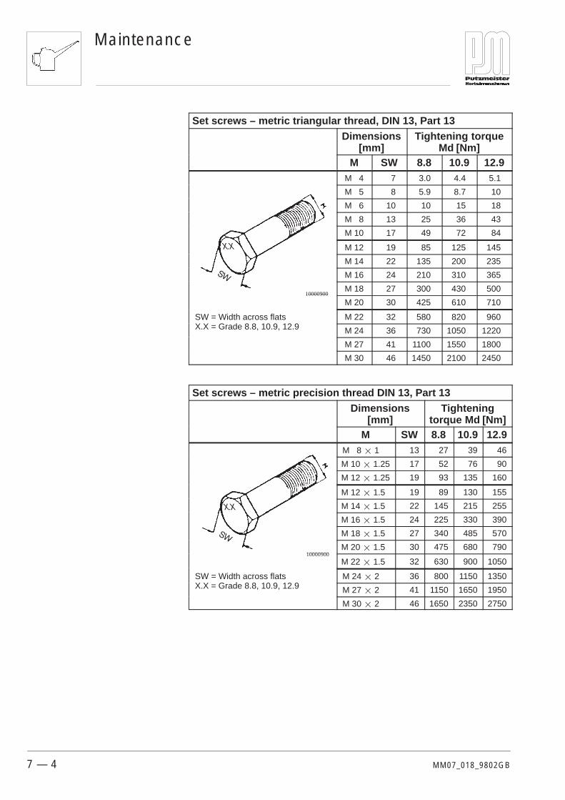
Tightening torques depend on bolt grade, thread friction and bolthead bearing area. The values given in the following tables are forguidance. These values should only be used if no other values arespecified in the relevant chapters of the Operating Instructions or inspare parts sheets.
Caution Bolts must always be replaced with bolts of the same size and grade.
Bolts with adhesive in the locking threads and self-locking nuts mustalways be replaced after removal.
The tables below give the maximum tightening torques (maximumtorque) in Nm for a friction factor of µtotal = 0.14, with the threadlightly-oiled or lightly-greased.
Note All tightening torques � 1.1 apply for bolts with cement in thethread.
7.2 General tighteningtorques
Maintenance
7 — 4 MM07_018_9802GB
Set screws – metric triangular thread, DIN 13, Part 13Dimensions
[mm]Tightening torque
Md [Nm]M SW 8.8 10.9 12.9
M 4 7 3.0 4.4 5.1
M 5 8 5.9 8.7 10
M 6 10 10 15 18
M 8 13 25 36 43
M 10 17 49 72 84
M 12 19 85 125 145
M 14 22 135 200 235
M 16 24 210 310 365
10000900M 18 27 300 430 500
10000900
M 20 30 425 610 710
SW = Width across flatsX X G d 8 8 10 9 12 9
M 22 32 580 820 960X.X = Grade 8.8, 10.9, 12.9 M 24 36 730 1050 1220
M 27 41 1100 1550 1800
M 30 46 1450 2100 2450
Set screws – metric precision thread DIN 13, Part 13Dimensions
[mm]Tightening
torque Md [Nm]M SW 8.8 10.9 12.9
M 8 � 1 13 27 39 46
M 10 � 1.25 17 52 76 90
M 12 � 1.25 19 93 135 160
M 12 � 1.5 19 89 130 155
M 14 � 1.5 22 145 215 255
M 16 � 1.5 24 225 330 390
M 18 � 1.5 27 340 485 570
10000900M 20 � 1.5 30 475 680 790
10000900
M 22 � 1.5 32 630 900 1050
SW = Width across flatsX X G d 8 8 10 9 12 9
M 24 � 2 36 800 1150 1350X.X = Grade 8.8, 10.9, 12.9 M 27 � 2 41 1150 1650 1950
M 30 � 2 46 1650 2350 2750

Maintenance
7 — 5MM07_018_9802GB
We have listed the suitable lubricants in the table below. Putzmeisteraccepts no liability for the quality of the lubricants listed or forchanges in quality made by the lubricant producer without changingthe grade designation.
Note Putzmeister accepts no liability for damaged caused by mixing oilsfrom different producers.
Engine oil Transmission oil Lubrication(manual)
Centralized lu-brication system
Marking in accordancewith DIN 51502 HD HYP K2K–20 K1K–20
Requirementsstandard API CD/SF API GL4 DIN 51 825 DIN 51 825
Characteristics mineral mineral, lithium soap
Viscosity grade,NLGI Class
SAE 15W–40DIN 51511
SAE 90DIN 51512standard
SAE 80DIN 51512
winter
NLGI Class 2DIN 51818
NLGI Class 1DIN 51818
Part no.000173005
Part no.000101006
— Part no.360000009
Part no.360001008
Aral MultiTurboral engine oilSAE 15W–40
Aral transmissionoilHYP SAE 85W–90
Aral transmissionoilHYP SAE 80W
Aral Aralub HL 2Aral multipurposegrease
—
BP VanellusMultigrade
BP EnergearEP 90
BP EnergearEP 80W
BP EnergreaseLS 2BP multipurposegrease L2
BP EnergreaseLS–EP 1
DEA CronosSuper DXSAE 15W–40
Deagear EP–ASAE 85W–90
Deagear EP–ASAE 80W
Glissando 20 Paragon EP 1
ELFPERFORMANCEXC 15W–40
TRANSELF EPSAE 80W–90
TRANSELF EPSAE 80W
ELF MULTI 2 ELF ROLEXA 1
ESSOLUBEMHX 15W–40
ESSO GEAR OILGP–D 85W–90
ESSO GEAR OILGP D 80W
BEACON 2 BEACON EP 1
Mobil DelvacSuper 1300
MobilubeGX 85W–90A
MobilubeGX 80W–A
Mobilux 2 —
Shell Rimula TX Shell SpiraxEP 90
Shell SpiraxMA 80 W
Shell Retinax AShellAlvania EPgrease 1
WintershallMulti-Rekord
WiolinMultipurpose trans-mission oil 85W-90
WiolinMultipurpose trans-mission oil 80W
Wiolub LFK 2 Wiolub LFM 1
7.3 Lubricantrecommendation

Maintenance
7 — 6 MM07_018_9802GB
You must proceed as follows in opening the engine cover before youcarry out any maintenance work in the engine compartment:
� Place a timber block on the Targa frame between the lifting eyeand the engine cover.� This ensures that the engine cover is not damaged by thelifting eye when it is folded open.
� Rase the engine cover as far as the stop.
24001300
12 3
4
1 Timber block2 Lifting eye3 Engine cover4 Gas-filled spring
� Now use a screwdriver to lift the retaining strap for the pivotjoint at the head of the gas-filled spring slightly or remove it(keep in a safe place).
� Lift the engine cover slightly and detach the gas-filled springdevice moving it to one side.
� Now repeat the same procedure on the opposite side of themachine.
7.4 Maintenance work in theengine compartment

Maintenance
7 — 7MM07_018_9802GB
Danger The engine cover could fall once both gas-filled springs have beendetached – risk of injury.
For this reason, rest the engine cover back on the timber block assoon as the gas-filled springs have been detached.
24001400
2
1
1 Engine cover2 Timber block
The engine compartment is now freely accesible.


40–001Page 1 of 1
Maintenance Chart
7 — 9WK40_001_9512GB
This maintenance chart describes visual checks which you mustcarry out before each maintenance task. You will find the mainte-nance intervals in the maintenance summary at the start of this chap-ter.
No further maintenance charts required.
No special tools required.
Danger Inspect the electrical cables particularly closely and carefully. Thereis a danger of flash over from damaged cables, particularly whenthere is high air or ambient humidity.
The general visual inspections which follow should be carried outbefore each job as well as before all maintenance work.
� Check that all safety equipment is available and in a fullyfunctioning condition.
Should you locate any damage to the electrical system, you musthave the damage rectified immediately by a qualified electrician.
� Check that all electrical connections are secure and free fromcorrosion.
� Check that the electrical cables have no breaks.
� Check the insulation on the electrical cables.
40–001 Visual checks
General
Electrical system

Maintenance Chart40–006Page 1 of 2
7 — 10 WK40_006_9802GB
This maintenance chart shows you the location of the lubricationnipples for lubricating with a grease gun. You will find the mainte-nance intervals in the maintenance summary at the start of thischapter.
No further maintenance charts required.
The following special tool is required:Grease gun
24200800
Lubricate the machine at the lubricant nipples using the greasegun.
40–006 Lubrication diagram
Lifting mixer

40–006Page 2 of 2
Maintenance Chart
7 — 11WK40_006_9802GB
24200900
Lubricate the machine at the lubricant nipples using the greasegun.
Tipping mixer

Maintenance Chart41–003Page 1 of 3
7 — 12 WK41_003_9802GB
This maintenance chart describes how to clean the solenoid. Themaintenance intervals are shown in the maintenance summary at thestart of this chapter.
No further maintenance charts required.
No special tools required.
14100200
1 Diesel engine solenoid
The starting solenoid for the diesel engine can become stiff fromdeposits of oil. This will mean that the machine will not start well. Toprevent this occurring, dismantle the solenoid every six months –particularly at the beginning of the cold season – and clean asfollows:
� Connect the solenoid to a power source:Black to negativeBlue/red and white to positiveAmperage 50 ACable size 2.5
41–003 Cleaning the solenoid
41–003Page 2 of 3
Maintenance Chart
7 — 13WK41_003_9802GB
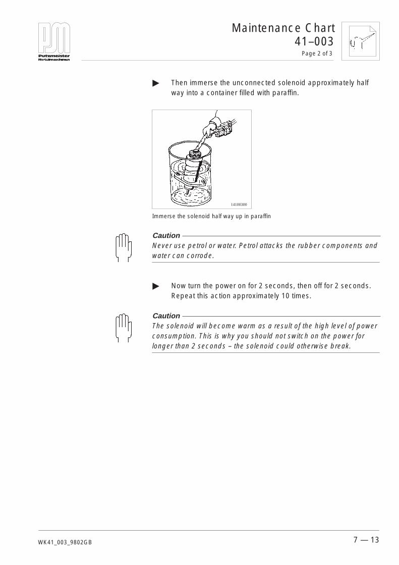
� Then immerse the unconnected solenoid approximately halfway into a container filled with paraffin.
14100300
Immerse the solenoid half way up in paraffin
Caution Never use petrol or water. Petrol attacks the rubber components andwater can corrode.
� Now turn the power on for 2 seconds, then off for 2 seconds.Repeat this action approximately 10 times.
Caution The solenoid will become warm as a result of the high level of powerconsumption. This is why you should not switch on the power forlonger than 2 seconds – the solenoid could otherwise break.

Maintenance Chart41–003Page 3 of 3
7 — 14 WK41_003_9802GB
� Switch off the solenoid and remove it from the paraffin-filledcontainer. Then switch it on and off again another 5–6 times toallow the remaining paraffin to drain out of the solenoid.
14100400
Remove the solenoid from the paraffin-filled container.
Caution Do not overheat the solenoid since this may cause it to break.
� Now remove the plug and clean the outside of the solenoid.
14100500
Rub down the solenoid with a cleaning cloth
43–007Page 1 of 3
Maintenance Chart
7 — 15WK43_007_9802GB
This maintenance chart describes how to fit the ribbed V-belt on thecompressor. You will find the maintenance intervals in the mainte-nance summary at the start of this chapter.
No further maintenance charts required.
The following special tool is required:Special spanner
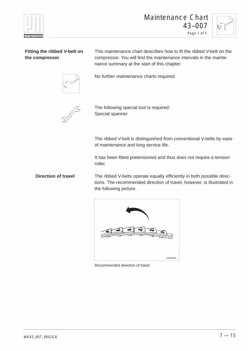
The ribbed V-belt is distinguished from conventional V-belts by easeof maintenance and long service life.
It has been fitted pretensioned and thus does not require a tensionroller.
The ribbed V-belts operate equally efficiently in both possible direc-tions. The recommended direction of travel, however, is illustrated inthe following picture.
14300400
Recommended direction of travel
43–007 Fitting the ribbed V-belt onthe compressor
Direction of travel

Maintenance Chart43–007Page 2 of 3
7 — 16 WK43_007_9802GB
Proceed as follows if you do not know the length of the belt:
� Use the spanner included with the belt to remove anapproximate length from the roll.
To remove: turn the rivet heads 90�. Insert the spanner and tilt it.
To fasten: push the rivets through the holes in the V-belt and turn the rivets 90� using the spanner.
� Place the belt around the V-belt pulley to determine the length.
14300500
Determining the length of the belt.
� Count the links and remove one link in 11 to obtain the requiredpretensioning.
14300600
Removing the ribs
Assembly

43–007Page 3 of 3
Maintenance Chart
7 — 17WK43_007_9802GB
� Now place the belt around the V-belt pulley axles and join it up.
14300700
Joining up the V-belt
� Place the belt in the groove of the small V-belt pulley. Nowrotate the large pulley slowly to allow the links to sit in thegroove.
14300800
Allowing the V-belt to sit in the groove
Note The ribbed V-belt pretension is approximately 2–3 times higher thanthat of conventional V-belts (8–9% of belt length).

Maintenance Chart44–001Page 1 of 3
7 — 18 WK44_001_9711GB
This maintenance chart describes how to inspect and replace thehydraulic hoses. You will find the maintenance intervals in the main-tenance summary at the start of this chapter.
No further maintenance charts required.
No special tools required.
Note Check all hoses (including hose fittings) with the machine running.You must replace the hoses at the slightest sign of damage or evenmere indications of threatened damage.
10400800
Check hydraulic hoses
Dark and moist patches on the fitting are external signs of incipientdamage. Check– the hoses for kinks, cracks or a porous surface and– whether the hoses have been laid without restrictions.
Note Beware of strong sunlight, the action of heat and the effects ofchemicals.
44–001 Hoses
Leaking hoses

44–001Page 2 of 3
Maintenance Chart
7 — 19WK44_001_9711GB
10400100
Tighten until there is a clearly perceptible increase in force
� Check whether the flared screwed joints are tight.
Note You may only tighten leaking flared screwed joints with the permittedtorque. Tighten the threaded union until you clearly feel an increasein the force required if you do not have a torque wrench available.You must replace these flared screwed joints if leaking continues.
Flared screwed joints
Externaldiameter
Model Md [Nm] Externaldiameter
Model Md [Nm]
6 L 20 18 L 120
8 L 40 20 S 250
12L 55 25 S 400
12S 80 30 S 500
15 L 70 38 S 800
16 S 130
Flared screwed joints
Maintenance Chart44–001Page 3 of 3
7 — 20 WK44_001_9711GB
The procedure for replacing hoses is as follows:
� Shut down the machine and secure against unauthorizedstarting.
� Dump fully any (residual) pressure in the hydraulic system.
Danger Hydraulic hoses may be mechanically prestressed. There is a risk ofinjury from whipping hoses.
� Take care when undoing the joints.
� Close the connection points with a plug immediately you haveremoved the old hoses. No dirt may enter the hydraulic circuitand the hydraulic circuit must not be drained.
Danger Hoses may not be more than six years old, including a storageperiod of two years. Take note of the date of manufacture on thehoses.
� Keep the hoses free from dirt.
� Fit the hoses to be free from bends or points of abrasion.
� Bleed the hydraulic system.
� Carry out a test run and inspect all hoses again after fitting newhoses.
Environmental protection Collect escaping fluid in a collector and dispose of it in an environ-mentally friendly manner.
Replacing hoses
44–008Page 1 of 2
Maintenance Chart
7 — 21WK44_008_9709GB
This maintenance chart describes how to set the values for the waterpressure and compressed air switches.
No further maintenance charts required.
No special tools required.
You must remove the casing covers for the switches before you setthe water pressure switch.
� Remove the central screw on the cover with a screwdriver.
� Pull the cover upwards to remove.
Compressed air switch On setting 1.8 barOff setting 2.3 bar
44–008 Setting values for the waterpressure and compressedair switches
Preparation
Setting values

Maintenance Chart44–008Page 2 of 2
7 — 22 WK44_008_9709GB
Use a suitable screwdriver and proceed as follows:
� Set the upper switching value you require using screw 3.� The setting value is displayed on scale 2.
� Set the lower switching value you require using screw 4.� The setting value is displayed on scale 5.
Note You can obtain precise settings if you use the the pressure gauge forcomparison.
+–
34
2
5
+–
1
1 Pressure switch2 Pressure display for the upper switching value3 Adjusting screw for the upper switching value4 Adjusting screw for the lower switching value5 Pressure display for the lower switching value
� Refasten the cover to the casing with the bolt.
To adjust

44–019Page 1 of 2
Maintenance Chart
7 — 23WK44_019_9802GB
This maintenance chart describes how to change the oil in thecompressor. You will find the maintenance intervals in the mainte-nance summary at the start of this chapter.
No further maintenance charts required.
No special tools required.
Note You must make it impossible for dirt or other impurities to enter thecompressor’s oil system. The compressor’s function can be impairedby small particles. Never leave oil filler cap off longer than necessary.
Change the oil once the compressor has warmed up.
Note Use engine oil graded SAE 15 W 40. Putzmeister MörtelmaschinenGmbH recommends VEBA OEL Logenta Universal oil or ViradaLonglife.
The following tasks must be completed before starting the full oilchange:
� Switch off the machine.
Environmental protection Always collect the old compressor oil. Guard against oil spillage.Comply with regulations when disposing of any oil caught.
44–019 Changing the oil in thecompressor
Preparation
Maintenance Chart44–019Page 2 of 2
7 — 24 WK44_019_9802GB
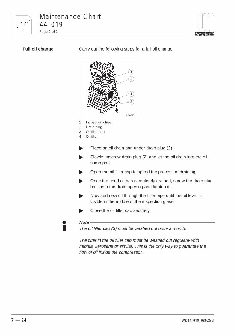
Carry out the following steps for a full oil change:
14300301
2
1
3
4
1 Inspection glass2 Drain plug3 Oil filler cap4 Oil filler
� Place an oil drain pan under drain plug (2).
� Slowly unscrew drain plug (2) and let the oil drain into the oilsump pan.
� Open the oil filler cap to speed the process of draining.
� Once the used oil has completely drained, screw the drain plugback into the drain opening and tighten it.
� Now add new oil through the filler pipe until the oil level isvisible in the middle of the inspection glass.
� Close the oil filler cap securely.
Note The oil filler cap (3) must be washed out once a month.
The filter in the oil filler cap must be washed out regularly withnaphta, kerosene or similar. This is the only way to guarantee theflow of oil inside the compressor.
Full oil change
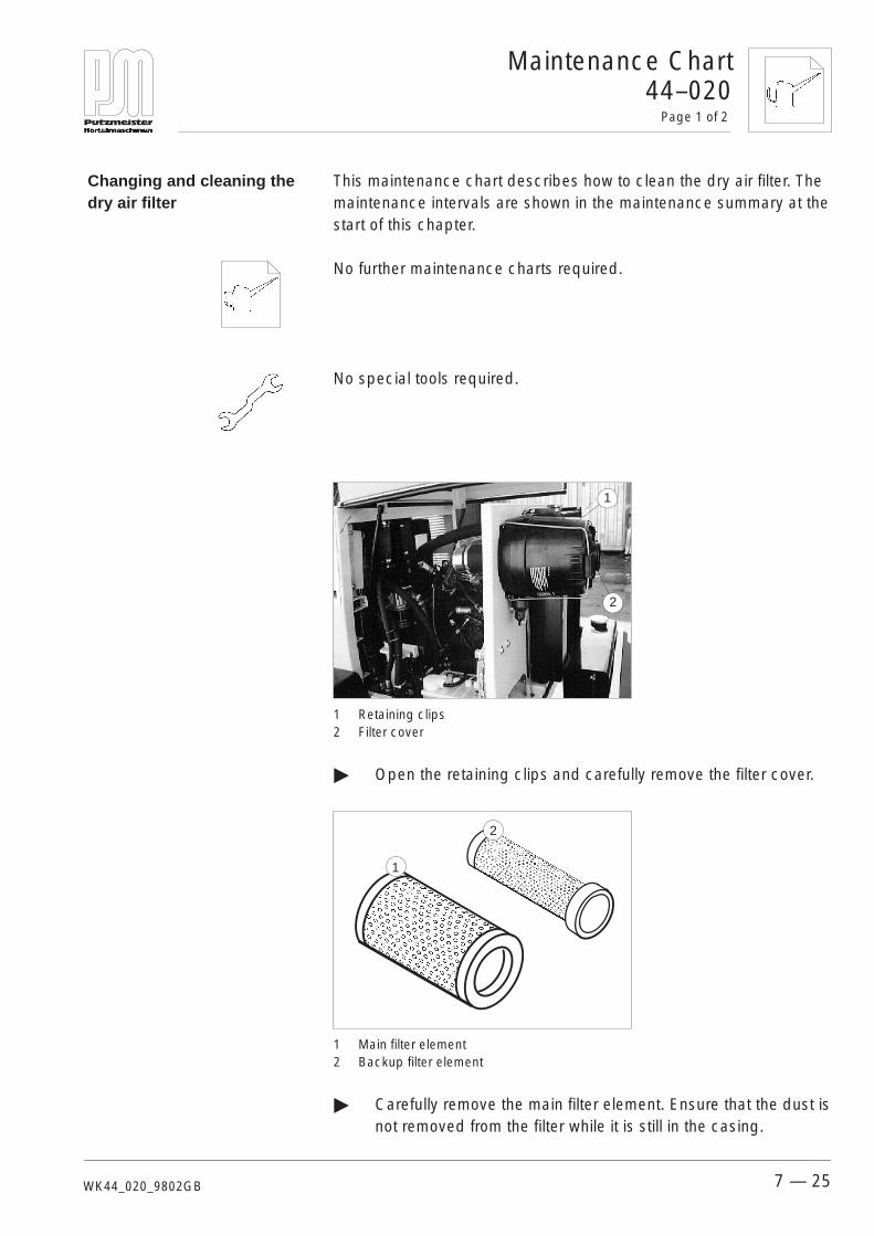
44–020Page 1 of 2
Maintenance Chart
7 — 25WK44_020_9802GB
This maintenance chart describes how to clean the dry air filter. Themaintenance intervals are shown in the maintenance summary at thestart of this chapter.
No further maintenance charts required.
No special tools required.
1
2
1 Retaining clips2 Filter cover
� Open the retaining clips and carefully remove the filter cover.
1
2
1 Main filter element2 Backup filter element
� Carefully remove the main filter element. Ensure that the dust isnot removed from the filter while it is still in the casing.
44–020 Changing and cleaning thedry air filter

Maintenance Chart44–020Page 2 of 2
7 — 26 WK44_020_9802GB
Note The main filter element should be replaced after the third cleaning, orannually. The backup filter element protects the engine from damagefor a limited time if the main filter element is damaged.The backup filter element must not be cleaned. It should bechanged after either the third cleaning of the main filter element or atleast once a year.
Be sure to replace the backup filter element as well if you notice thatthe main filter element is damaged when you check it.
� Check the main filter element for damage and then clean itinside and out with compressed air. Change the filter element ifthe machine is very dirty or there are heavy oil deposits.
Face-mask and respiratory protectorA face-mask and respiratory protector protect you against particlesof dust entering your body through your respiratory passages.
� Clean the sealing surface and the inside of the outlet pipe.
� Reassemble the parts in reverse order.

44–021Page 1 of 3
Maintenance Chart
7 — 27WK44_021_9802GB
This maintenance chart describes how to carry out a full fluid changeon the hydraulic system. You will find the maintenance intervals in themaintenance summary at the start of this chapter.
Refer also to the maintenance charts:Function checksHydraulic filter changeHoses
No special tools required.
Note Cleanliness is of the greatest possible importance in the maintenanceof hydraulic systems. You must make it impossible for dirt or otherimpurities to enter the system. Even small particles may cause valvesto be scored, pumps to seize and throttle and control bores tobecome blocked. Never leave the reservoir lid open longer thannecessary.
The following tasks must be completed before starting the full fluidchange:
� Switch the pump off.
� Switch the power unit off.
� Secure the machine against unauthorized starting – switch offthe ignition lock.
� Secure your working area and fix notices to the locked controlsand setting devices.
44–021 Changing the hydraulicfluid
Preparation
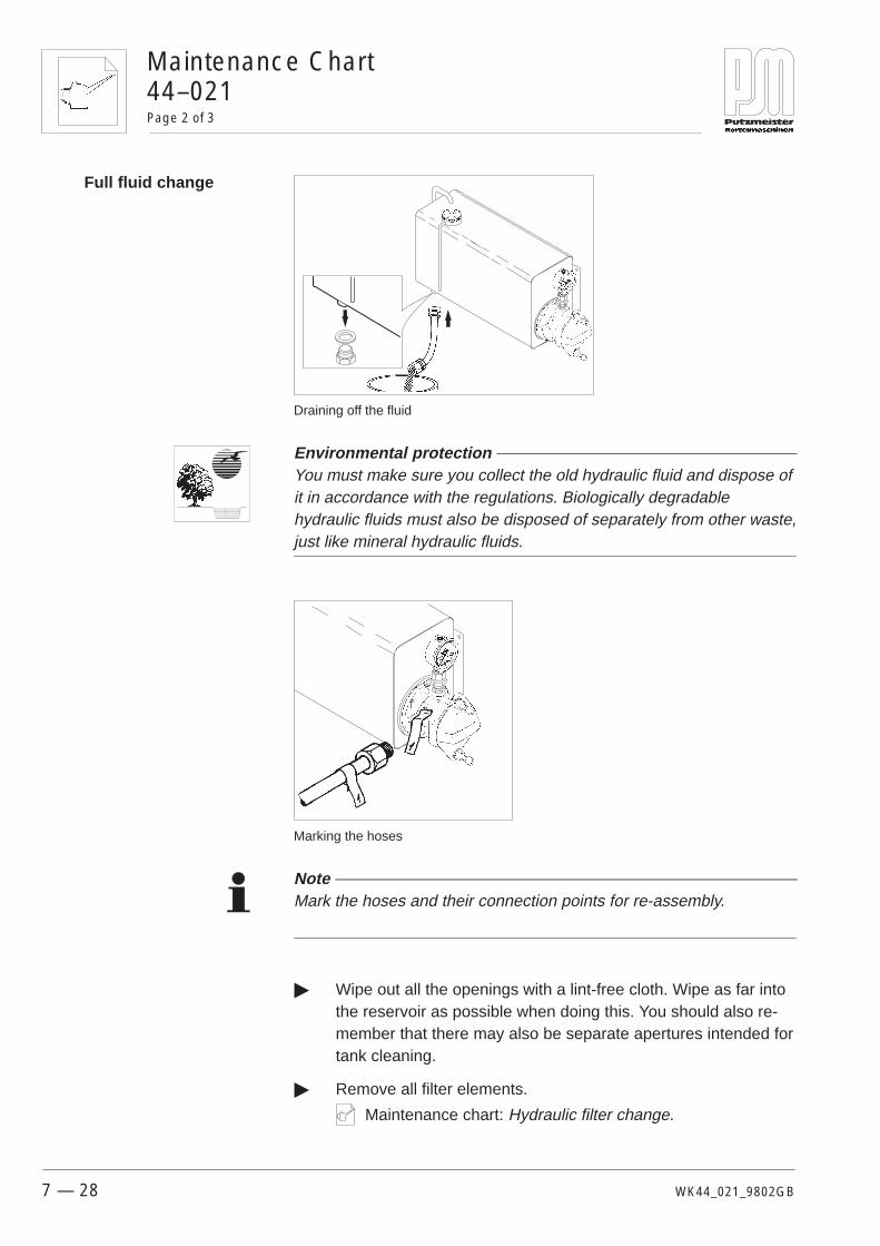
Maintenance Chart44–021Page 2 of 3
7 — 28 WK44_021_9802GB
Draining off the fluid
Environmental protection You must make sure you collect the old hydraulic fluid and dispose ofit in accordance with the regulations. Biologically degradablehydraulic fluids must also be disposed of separately from other waste,just like mineral hydraulic fluids.
Marking the hoses
Note Mark the hoses and their connection points for re-assembly.
� Wipe out all the openings with a lint-free cloth. Wipe as far intothe reservoir as possible when doing this. You should also re-member that there may also be separate apertures intended fortank cleaning.
� Remove all filter elements.
Maintenance chart: Hydraulic filter change.
Full fluid change
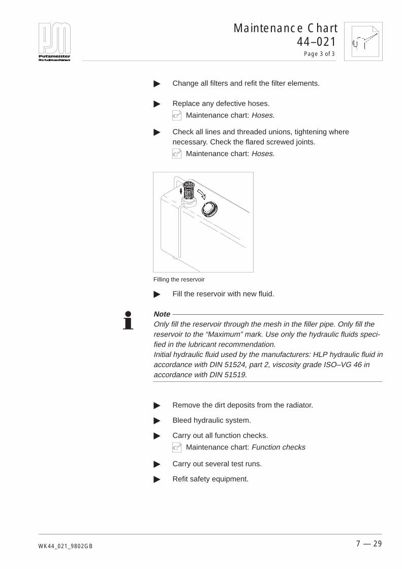
44–021Page 3 of 3
Maintenance Chart
7 — 29WK44_021_9802GB
� Change all filters and refit the filter elements.
� Replace any defective hoses.
Maintenance chart: Hoses.
� Check all lines and threaded unions, tightening wherenecessary. Check the flared screwed joints.
Maintenance chart: Hoses.
Filling the reservoir
� Fill the reservoir with new fluid.
Note Only fill the reservoir through the mesh in the filler pipe. Only fill thereservoir to the “Maximum” mark. Use only the hydraulic fluids speci-fied in the lubricant recommendation.Initial hydraulic fluid used by the manufacturers: HLP hydraulic fluid inaccordance with DIN 51524, part 2, viscosity grade ISO–VG 46 inaccordance with DIN 51519.
� Remove the dirt deposits from the radiator.
� Bleed hydraulic system.
� Carry out all function checks.
Maintenance chart: Function checks
� Carry out several test runs.
� Refit safety equipment.

Maintenance Chart46–009Page 1 of 2
7 — 30 WK46_009_9709GB
This maintenance chart describes how to replace the auger. You willfind the maintenance intervals in the maintenance summary at thestart of this chapter.
Refer also to the maintenance charts:Dismantling the pressure flange Fitting the pressure flange
No special tools required.
Note Use only original Putzmeister spare parts.
34000300
Use original spare parts marked with the Putzmeister logo.
46–009 Replacing the auger

46–009Page 2 of 2
Maintenance Chart
7 — 31WK46_009_9709GB
1
2
3
4
1 Clamping sheath bolts2 Auger barrel3 Auger4 Clamping sheath
� Unscrew all clamping sheath bolts (1) and remove the augerbarrel (2) and auger (3) from the clamping sheath (4).
� Clamp the auger barrel (2) and remove the auger (3) by rotat-ing it anti-clockwise.
� Spray the new auger (3) with Putzmeister silicone spray.
� Insert the auger (3) into the clamped auger barrel (2), rotatingit clockwise.
� Line up the end of the auger (1) and the auger barrel (2) flush.
Caution The auger may only be treated with Putzmeister silicone spray beforefitting. Do not use used oil. Used oil attacks the rubber.

Maintenance Chart49–004Page 1 of 4
7 — 32 WK49_004_9802GB
This maintenance chart describes how to adjust the overrunningbrake. You will find the maintenance intervals in the maintenancesummary at the start of this chapter.
No further maintenance charts required.
No special tools required.
First, jack up the machine so that both wheels are clear of theground.
� Use the stabilizing wheel to lower machine at the front.
� Extend and lock the rear support legs.
� Use the stabilizing wheel to raise machine at the front.� Both wheels lose contact with the ground.
Caution Secure the machine to achieve the necessary stability. Only carry outmaintenance work on level ground.
49–004 Adjusting the overrunningbrake
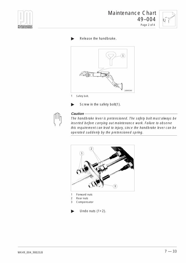
49–004Page 2 of 4
Maintenance Chart
7 — 33WK49_004_9802GB
� Release the handbrake.
24900300
1
1 Safety bolt.
� Screw in the safety bolt(1).
Caution The handbrake lever is pretensioned. The safety bolt must always beinserted before carrying out maintenance work. Failure to observethis requirement can lead to injury, since the handbrake lever can beoperated suddenly by the pretensioned spring.
2
3
1
1 Forward nuts2 Rear nuts3 Compensator
� Undo nuts (1+2).

Maintenance Chart49–004Page 3 of 4
7 — 34 WK49_004_9802GB
Begin by adjusting or readjusting the wheel brakes.
1. 2.
0,5
1
1 Adjusting nut
� To do this, turn each wheel in the direction of travel.
� Adjust the adjusting nut (1) by turning it clockwise until thebrake-shoes catch on the brake drum.� The wheel becomes harder to turn.
� Undo the adjusting bolt (1) half a turn.� The wheel runs freely and the brake-shoes no longer catchon the brake drum.
Carry out the same adjustment on the opposite wheel.
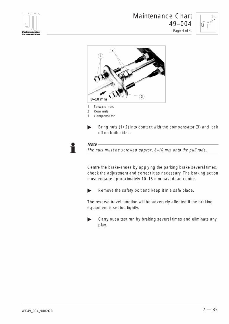
49–004Page 4 of 4
Maintenance Chart
7 — 35WK49_004_9802GB
2
3
1
8–10 mm
1 Forward nuts2 Rear nuts3 Compensator
� Bring nuts (1+2) into contact with the compensator (3) and lockoff on both sides.
Note The nuts must be screwed approx. 8–10 mm onto the pull rods.
Centre the brake-shoes by applying the parking brake several times,check the adjustment and correct it as necessary. The braking actionmust engage approximately 10–15 mm past dead centre.
� Remove the safety bolt and keep it in a safe place.
The reverse travel function will be adversely affected if the brakingequipment is set too tightly.
� Carry out a test run by braking several times and eliminate anyplay.


Index of Key Words
i
Index of Key Words
This chapter contains the main key words with the number of thepage on which they are to be found as a header in the left-handmargin. This Index of key words is listed alphabetically by the mainconcepts. These are subdivided into associated sub-concepts,marked with a dash.

Index of Key Words
ii
AAir pressure switch, Setting values, 7–21
BBlockages, 5–26- Rectifying, 5–26
CChanging the air filter, 7–25
Changing the hydraulic fluid, 7–27
Cleaning, 5–22- Compressed air cleaning, 5–23- Delivery line, 5–23- Diesel engine radiator, 5–25- Machine, 5–22- Spray gun, 5–24
Cleaning the solenoid, 7–12
Compressed air switch, 7–21
Compressor oil change, 7–23
DDesignated use, 3–12
Diesel engine control, 5–20
EEar defenders, 3–13
EMERGENCY SHUT-DOWN, 5–2
HHoses, Maintenance, 7–18
IIcons, 1–4
Interruption in work, 5–18
LLiability, Exclusion, 3–12
Loading, 4–5
Lubricant recommendation, 7–5
Lubrication diagram, 7–10- Lifting mixer, 7–10- Tipping mixer, 7–11
MMaintenance cards, Hoses, 7–18
Maintenance intervals, 7–1
Maintenance work in the engine compartment, 7–6
Mortar line, 5–21
Mortar mixture, 5–3- Additives, 5–5- Basic plastering mortar, 5–5- Binder, 5–4, 5–21- Cement mortar, 5–5- Consistence, 5–3- Sand, 5–4- Site mix, 5–5
NNoise, 3–13- Ear defenders, 3–13
Noise emission measurement, 2–8
OOperation, 5–10- Grille, 5–15- Mixing and starting to pump, 5–10- Mixing with the lifting mixer unit, 5–13- Mixing with the tipping mixer unit,
5–16- Mortar spraying, 5–18- Raising the mixer, 5–14
Overrunning brake, Adjusting, 7–33
Overview, 2–1- Lifting mixer, 2–1- Tipping mixer, 2–2
PPersonnel, 3–14- Qualified electricians, 3–14
Procedure in an emergency situation, 3–14
RRemote air control, 5–19
Ribbed V-belt, 7–15- Assembly, 7–16- Direction of travel, 7–15
SSafety equipment, 3–13
Set-up site, 4–6- Operations site, 4–6- Requirements, 4–6
Shut-down, 5–2
Starting up, 5–6- Starting up, 5–9
Symbols, 1–4
TTechnical data, 2–8
Torques, 7–3
Towing gear, 4–3
Transport, 4–4
UUse contrary to the designated use, 3–12
VVisual checks, 7–9
WWater pressure switch, 7–21- Setting values, 7–21

Putzmeister Mörtelmaschinen GmbHMax–Eyth–Straße 1072631 AichtalPostfach 21 5272629 AichtalTel. (0 71 27) 599–0Fax (0 71 27) 599–743
Putzmeister LimitedChesterfield Trading EstateCarrwood RoadSheepbridge/Chesterfield/Derbyshire S41 9QBTel. (0 12 46) 45 45 46Fax (0 12 46) 126 00 77
Putzmeister do BrasilMaquinas para ConstrucaoLtda.Estrada de Itapecerica, 4651Itapecerica da Serra–SP,CEP 06850–000Tel. (11) 495 70 55Fax (11) 495 63 94
Putzmeister Iberica S.A.Camino de Hormigueras 17328031 MadridTel. (1) 428 81 00Fax (1) 428 81 06
Putzmeister S.A. (Pty) Ltd .101, 10th Road, Kew 2090P.O. Box 396032018 Bramley/JohannesburgTel. (11) 882 61 23Fax (11) 882 66 47
Thomsen Machinery Co.Building A18601 South Main StreetGardena CA 90248Tel. (310) 769 45 00Fax (310) 516 98 20
Putzmeister FranceZone IndustrielleRue Jean Jaurès91861 Epinay sous SénartTel. (1) 69 39 69 39Fax (1) 60 47 20 68
Putzmeister AmericaMortar Maschine Division1251 North Red Gum StreetAnaheim, CA 92806Phone: (714) 688 12 00Fax: (714) 688 12 12
Putzmeister Japan Co. Ltd.Chitose Building9–4, Nihonbashi Kayabacho2–chome, Chou–Ku103 TokyoTel. (3) 5 641 1950Fax (3) 5 641 1955
Weitere Werksvertretungen mit Kundendienst in:
ÄgyptenAlgerienArgentinienAustralienBahrainBelgienBolivienBrasilienBulgarienChileChinaCosta RicaDänemarkDominikanischeRepublikEcuador
El SalvadorEnglandFinnlandFrankreichGriechenlandGuatemalaGUSHong KongIndienIndonesianIrakIranIslandIsraelItalienJapan
JemenJordanienehem.JugoslawienKanadaKatarKolumbienKoreaKubaKuwaitLibanonLibyenLuxemburgMalaysiaMaltaMauritius
MexikoNeuseelandNiederlandeNorwegenOmanÖsterreichPakistanPanamaParaguayPeruPhilippinenPolenPortugalSaudi–ArabienSchwedenSchweiz
SingapurSlovakeiSpanienSyrienTaiwanThailandTschechischeRepublikTürkeiTunesienUruguayUSAVenezuelaVereinigte Arabi-sche EmirateZypern

Putzmeister Mörtelmaschinen GmbHPostfach 2152D–72629 AichtalTelefon (07127) 599–0Telefax (07127) 599–743Internet: http://www.putzmeister.deE–mail: [email protected]