numerical investigation of the flow structures in a quasi...
TRANSCRIPT

20th Australasian Fluid Mechanics Conference Perth, Australia 5-8 December 2016
Numerical investigation of the flow structures in a quasi-axisymmetric scramjet
engine
K. Tanimizu1, T. Jones1, H. Ogawa1, and A. Pudsey1
1School of Engineering, RMIT University, Melbourne, Victoria 3001, Australia
Abstract
The flowfield characteristics of a relatively small quasi-axisymmetric scramjet vehicle at a Mach 6 flight condition have been investigated numerically. To this end, three-dimensional, compressible, turbulent, reacting flow calculations with a finite rate chemistry model consisting of 33 reactions and 13 species and two-equation SST k-ω RANS model have been performed. Hydrogen is used as the fuel and the injection pressure of fuel is varied from 1 to 7 MPa in order to study the effect of the injection pressure on the flowfields in the scramjet model. The combustion length has been found to decrease as the injection pressure increases. However, rather little thrust gain has been achieved by combustion heat release in the present configurations.
Introduction
The scramjet-powered vehicle offers promise for sustained hypersonic transport in the atmosphere. Therefore, over the past decades, in particular, considerable research efforts have been dedicated to the design and physics associated with various scramjet-powered configurations [4]. The Australian hypersonics community has been playing a significant role with a long history of successful milestones achieved in this research area, e.g., flight experiments including the HyShot II of The University of Queensland (UQ) in July 2002 [2, 11], and the hydrocarbon HIFiRE Flight 2 in May 2012 [7]. The hypersonics research group at RMIT University is recently initiated, focussing on the study of a quasi-axisymmetric class of scramjet engines. Paull et al. [12] demonstrated that one such quasi-axisymmetric scramjet vehicle could produce enough thrust to overcome drag thus yield positive net thrust over a limited range of conditions in experimental testing conducted in the T4 Stalker tube shock tunnel at UQ. They analysed the performance of the vehicle by comparing the measurements with results from simple hypersonic theories with appropriate modelling assumptions. However, the effect of shock-boundary layer interaction on the model performance was not taken into account in their analysis due to limitations, where it was difficult to conduct flow visualisation in this intake configuration unlike two-dimensional intakes. Consequently, the detailed flow structures in the intake section remained to be fully understood. One of the key requirements for successful flight is to reduce the time for ignition and combustion to values of the same order of magnitude as the mixture residence time inside the combustor. Paull et al. [12] used silane as an ignitor to reduce the time of combustion. Pudsey et al. [14] reported that the relation between the fuel mass flow rate and the ignition point. They suggested that the ignition point become shorter as the mass flow rate increased. In this study, three-dimensional Navier-Stokes simulations are performed to investigate the characteristics of the flowfields in a relatively small quasi-axisymmetric scramjet engine consisting of a conical forebody, side walls, and a cowl. A Mach 6 flight
condition is considered with and without fuel to gain physical insights into the detailed flow structure in the scramjet model and reveal the underlying mechanism responsible for the production of positive net thrust using the CFD solutions. In order to reduce the combustion length, the forebody injection is used instead of applying the other fuel injection systems [13]. The effects of the fuel-air ratios on the flow path are investigated. The fuel-air ratio is varied by changing the fuel injection pressures. The flowfields are scrutinised carefully in order to identify the key design factors and driving flow physics for future scramjet design.
Approaches
Computational methods
Figure 1 shows a schematic diagram of the present numerical configuration and boundary conditions. In this study, the calculations start at x/d = 1, where x is the distance from the tip of the conical forebody and d is the diameter of the scramjet model. The flow simulations for the forward section of the conical forebody with the fuel injections are separately investigated by Jones et al. [8]. A high-fidelity analysis for the current flowfield is conducted by solving the three-dimensional Reynolds-averaged Navier-Stokes equations. The particular flow solver used is the commercial code CFD++, which is capable of solving the steady or unsteady Navier-Stokes equations for incompressible or compressible flow, including the finite rate chemistry with multiple species [3]. In this present study, the boundary layer is assumed to be turbulent, modelled by using the two-equation SST k-ω RANS model [10]. This turbulence model is a well-established model, commonly used for hypersonic air-breathing applications [9, 14]. A finite rate chemistry model proposed by Jachimowski [6] has been used as the combustion model, which consists of 33 reactions and 13 species for hydrogen-air combustion. The wall is assumed to be adiabatic surface. The inflow boundary condition is imposed by inflow profiles, which are obtained from a separate study of the fuel injection system conducted by Jones et al. [8]. All calculations are terminated when the both energy residual and non-dimensional mass balance between inflow and outflow reduce to an order of 10-5, based on a convergence dependency study.
Figure 1. Schematic diagram of the numerical setup and boundary conditions.
Present research area
IntakeCombustor Nozzle
Centrebody
Cowl
Flow simulation for Fuel Injection study
Adiabatic wall
Supersonic outflow
Inflow profile
Flow direction

Geometry, grid and flow conditions
The quasi-axisymmetric scramjet model investigated in this study is developed by referring to the configuration used by Paull et al. [12]. It has a 9° half-angle conical forebody, and 10° half-angle conical afterbody. The inlets and combustion chamber entrances consist of compression ramps formed by eight splitters which deflect the flow that has already passed through the conical forebody shock by a further 10.0°. The straight constant area combustion chambers are composed of the centrebody, the cowl, and the splitters. Expansion nozzles with a 10° deflection angle are formed by the afterbody, the cowl, and the splitters. The computational domain is represented by a three-dimensional structured (hexahedral) mesh generated by a commercial grid generator GridPro [5]. The GridPro utility was used to achieve a near wall spacing of 10-7 m. This space corresponds to y+ values of less than 0.5 for most of the cases in order to ensure good resolution of the viscous sub-layer. The grid consists of 2023 blocks and 6.9 million cells in total (Figure 2).
Figure 2. Computational mesh used for the present study.
Table 1 shows the flow conditions used for the present study. For the fuel-on cases, hydrogen is injected at x/d = 0.25 [8].
Flow conditions Mean velocity 1181.6 m/s Mean pressure 800 kPa
Mean temperature 1233.3 K Fuel injection pressure 1, 2, 3, and 7 MPa
Fuel injection temperature 300 K
Table 1. Flow conditions at the combustor entrance.
Note that the fuel injection pressures 1, 2, 3, and 7MPa correspond with the fuel/air equivalence ratios of approximately 0.11, 0.23, 0.34 and 0.79, respectively.
Results and discussions
Fuel-off case
Figure 3 displays the Mach number distribution in the prototype baseline model of the scramjet on the combustor centreline symmetry plane with the non-fuel condition. It can be seen that the flow is not entirely captured by the cowl as a result of the effect of the bluntness of the conical forebody, with some flow spilled out of the cowl. A bow shock is generated at the crotch of the cowl. These result in additional external drag on the scramjet. An expansion wave is observed at the expansion corner of the cowl leading edge. A substantial flow separation is also observed immediately after the expansion wave. As a consequence, flow near the outer surface of the cowl decelerates. This can significantly affect the total performance of the scramjet vehicle. The Mach number at the entrance of the combustor decreases to approximately 4 due to the oblique shocks generated at the side wall and cowl. Shock wave and boundary layer interactions occur at the lower surface of the combustor. These interactions lead to small flow separation in the combustion chamber. A large flow separation occurs at x/d = 4.5 downstream of the base of the
centrebody, which is designed for the connection with a boosting system. The total drag coefficient of the model for this condition is 0.196. Note that drag coefficient is defined here as
𝐶" ="
$%&'%(
(1)
,where D, 𝜌, V, and A are drag force, free stream density, free stream velocity and reference area (based on model diameter), respectively.
Figure 3. Mach number distribution on the symmetry plane (non-fuel case).
The distribution of the static temperature on the symmetry plane is shown in Figure 4. The temperature in the mainstream region of the combustor is slightly below the minimum temperature required for self-ignition (800 K [9]). On the other hand, the temperature near the wall is above 1000 K, sufficiently high for combustion. There is a small hot spot present at x/d = 2.1, where the temperature is approximately 2000 K.
Figure 4. Temperature distribution on the symmetry plane (non-fuel case).
Fuel-on case
Figures 5 and 6 show Mach number and temperature distributions on the symmetry plane for the injection pressure of 1 MPa. Compared to Figure 3, there is no significant change in the Mach number distribution due to fuel injection. As compared to Figure 4, slight temperature increase is observed in the entire region in the combustion chamber as a result of the combustion process near the wall. It is notable that the temperature reaches approximately 2500 K in the small hot spot.
Figure 5. Mach number distribution for injection pressure of 1 MPa.
Figures 7 and 8 show Mach number and temperature distributions on the symmetry plane for the injection pressure of 3 MPa.
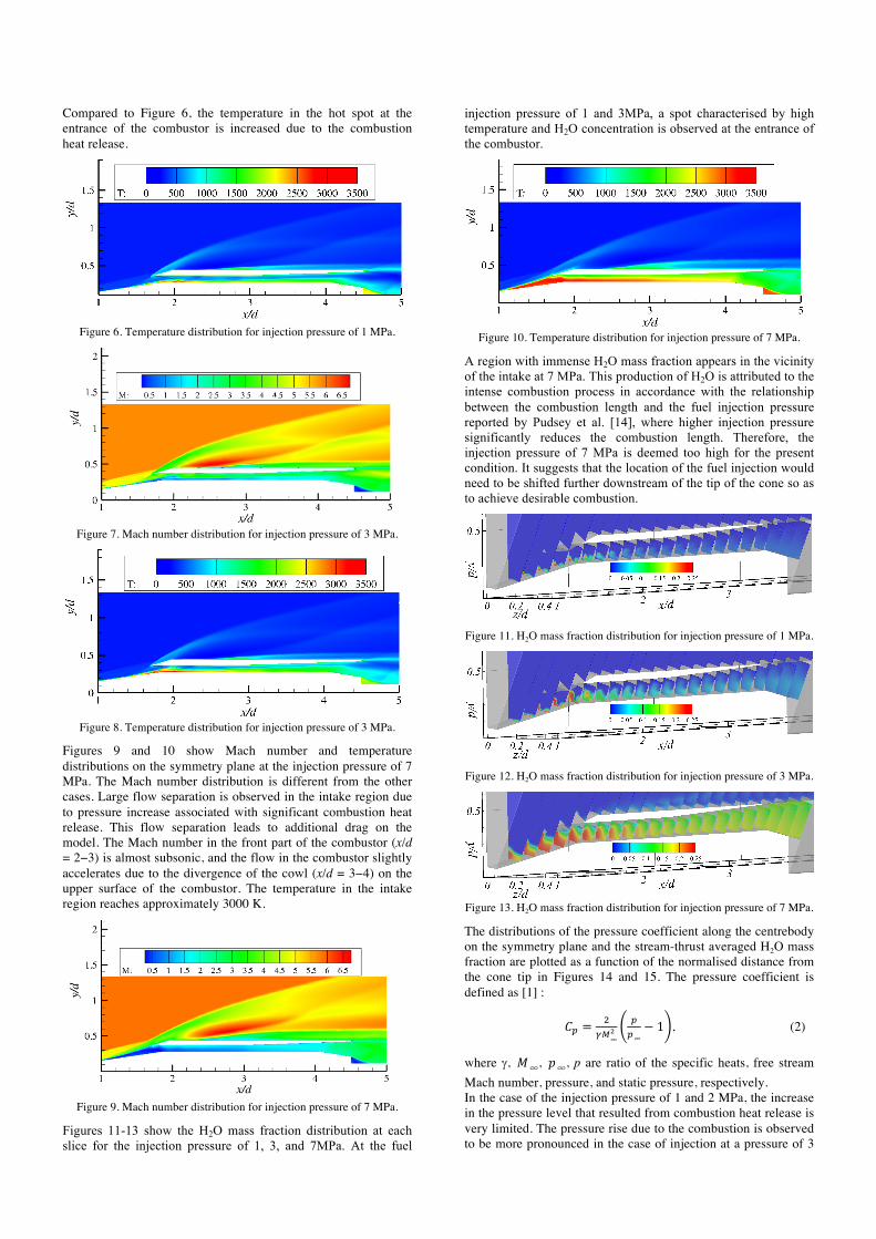
Compared to Figure 6, the temperature in the hot spot at the entrance of the combustor is increased due to the combustion heat release.
Figure 6. Temperature distribution for injection pressure of 1 MPa.
Figure 7. Mach number distribution for injection pressure of 3 MPa.
Figure 8. Temperature distribution for injection pressure of 3 MPa.
Figures 9 and 10 show Mach number and temperature distributions on the symmetry plane at the injection pressure of 7 MPa. The Mach number distribution is different from the other cases. Large flow separation is observed in the intake region due to pressure increase associated with significant combustion heat release. This flow separation leads to additional drag on the model. The Mach number in the front part of the combustor (x/d = 2−3) is almost subsonic, and the flow in the combustor slightly accelerates due to the divergence of the cowl (x/d = 3−4) on the upper surface of the combustor. The temperature in the intake region reaches approximately 3000 K.
Figure 9. Mach number distribution for injection pressure of 7 MPa.
Figures 11-13 show the H2O mass fraction distribution at each slice for the injection pressure of 1, 3, and 7MPa. At the fuel
injection pressure of 1 and 3MPa, a spot characterised by high temperature and H2O concentration is observed at the entrance of the combustor.
Figure 10. Temperature distribution for injection pressure of 7 MPa.
A region with immense H2O mass fraction appears in the vicinity of the intake at 7 MPa. This production of H2O is attributed to the intense combustion process in accordance with the relationship between the combustion length and the fuel injection pressure reported by Pudsey et al. [14], where higher injection pressure significantly reduces the combustion length. Therefore, the injection pressure of 7 MPa is deemed too high for the present condition. It suggests that the location of the fuel injection would need to be shifted further downstream of the tip of the cone so as to achieve desirable combustion.
Figure 11. H2O mass fraction distribution for injection pressure of 1 MPa.
Figure 12. H2O mass fraction distribution for injection pressure of 3 MPa.
Figure 13. H2O mass fraction distribution for injection pressure of 7 MPa.
The distributions of the pressure coefficient along the centrebody on the symmetry plane and the stream-thrust averaged H2O mass fraction are plotted as a function of the normalised distance from the cone tip in Figures 14 and 15. The pressure coefficient is defined as [1] :
𝐶* =+
,-∞%
**∞
− 1 , (2)
where g, 𝑀∞, 𝑝∞, p are ratio of the specific heats, free stream Mach number, pressure, and static pressure, respectively. In the case of the injection pressure of 1 and 2 MPa, the increase in the pressure level that resulted from combustion heat release is very limited. The pressure rise due to the combustion is observed to be more pronounced in the case of injection at a pressure of 3
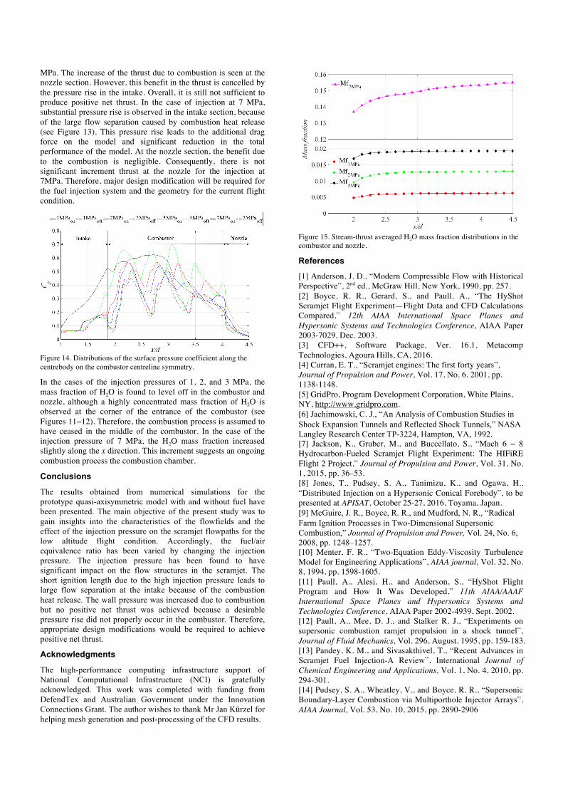
MPa. The increase of the thrust due to combustion is seen at the nozzle section. However, this benefit in the thrust is cancelled by the pressure rise in the intake. Overall, it is still not sufficient to produce positive net thrust. In the case of injection at 7 MPa, substantial pressure rise is observed in the intake section, because of the large flow separation caused by combustion heat release (see Figure 13). This pressure rise leads to the additional drag force on the model and significant reduction in the total performance of the model. At the nozzle section, the benefit due to the combustion is negligible. Consequently, there is not significant increment thrust at the nozzle for the injection at 7MPa. Therefore, major design modification will be required for the fuel injection system and the geometry for the current flight condition.
Figure 14. Distributions of the surface pressure coefficient along the centrebody on the combustor centreline symmetry.
In the cases of the injection pressures of 1, 2, and 3 MPa, the mass fraction of H2O is found to level off in the combustor and nozzle, although a highly concentrated mass fraction of H2O is observed at the corner of the entrance of the combustor (see Figures 11−12). Therefore, the combustion process is assumed to have ceased in the middle of the combustor. In the case of the injection pressure of 7 MPa, the H2O mass fraction increased slightly along the x direction. This increment suggests an ongoing combustion process the combustion chamber.
Conclusions
The results obtained from numerical simulations for the prototype quasi-axisymmetric model with and without fuel have been presented. The main objective of the present study was to gain insights into the characteristics of the flowfields and the effect of the injection pressure on the scramjet flowpaths for the low altitude flight condition. Accordingly, the fuel/air equivalence ratio has been varied by changing the injection pressure. The injection pressure has been found to have significant impact on the flow structures in the scramjet. The short ignition length due to the high injection pressure leads to large flow separation at the intake because of the combustion heat release. The wall pressure was increased due to combustion but no positive net thrust was achieved because a desirable pressure rise did not properly occur in the combustor. Therefore, appropriate design modifications would be required to achieve positive net thrust.
Acknowledgments
The high-performance computing infrastructure support of National Computational Infrastructure (NCI) is gratefully acknowledged. This work was completed with funding from DefendTex and Australian Government under the Innovation Connections Grant. The author wishes to thank Mr Jan Kürzel for helping mesh generation and post-processing of the CFD results.
Figure 15. Stream-thrust averaged H2O mass fraction distributions in the combustor and nozzle.
References
[1] Anderson, J. D., “Modern Compressible Flow with Historical Perspective”, 2nd ed., McGraw Hill, New York, 1990, pp. 257. [2] Boyce, R. R., Gerard, S., and Paull, A., “The HyShot Scramjet Flight Experiment—Flight Data and CFD Calculations Compared,” 12th AIAA International Space Planes and Hypersonic Systems and Technologies Conference, AIAA Paper 2003-7029, Dec. 2003. [3] CFD++, Software Package, Ver. 16.1, Metacomp Technologies, Agoura Hills, CA, 2016. [4] Curran, E. T., “Scramjet engines: The first forty years”, Journal of Propulsion and Power, Vol. 17, No. 6, 2001, pp. 1138-1148. [5] GridPro, Program Development Corporation, White Plains, NY, http://www.gridpro.com. [6] Jachimowski, C. J., “An Analysis of Combustion Studies in Shock Expansion Tunnels and Reflected Shock Tunnels,” NASA Langley Research Center TP-3224, Hampton, VA, 1992. [7] Jackson, K., Gruber, M., and Buccellato, S., “Mach 6 − 8 Hydrocarbon-Fueled Scramjet Flight Experiment: The HIFiRE Flight 2 Project,” Journal of Propulsion and Power, Vol. 31, No. 1, 2015, pp. 36–53. [8] Jones, T., Pudsey, S. A., Tanimizu, K., and Ogawa, H., “Distributed Injection on a Hypersonic Conical Forebody”, to be presented at APISAT, October 25-27, 2016, Toyama, Japan. [9] McGuire, J. R., Boyce, R. R., and Mudford, N. R., “Radical Farm Ignition Processes in Two-Dimensional Supersonic Combustion,” Journal of Propulsion and Power, Vol. 24, No. 6, 2008, pp. 1248–1257. [10] Menter, F. R., “Two-Equation Eddy-Viscosity Turbulence Model for Engineering Applications”, AIAA journal, Vol. 32, No. 8, 1994, pp. 1598-1605. [11] Paull, A., Alesi, H., and Anderson, S., “HyShot Flight Program and How It Was Developed,” 11th AIAA/AAAF International Space Planes and Hypersonics Systems and Technologies Conference, AIAA Paper 2002-4939, Sept. 2002. [12] Paull, A., Mee, D. J., and Stalker R. J., “Experiments on supersonic combustion ramjet propulsion in a shock tunnel”, Journal of Fluid Mechanics, Vol. 296, August, 1995, pp. 159-183. [13] Pandey, K. M., and Sivasakthivel, T., “Recent Advances in Scramjet Fuel Injection-A Review”, International Journal of Chemical Engineering and Applications, Vol. 1, No. 4, 2010, pp. 294-301. [14] Pudsey, S. A., Wheatley, V., and Boyce, R. R., “Supersonic Boundary-Layer Combustion via Multiporthole Injector Arrays”, AIAA Journal, Vol. 53, No. 10, 2015, pp. 2890-2906