sensitivity of instability mechanisms to trailing...
TRANSCRIPT

20th Australasian Fluid Mechanics ConferencePerth, Australia5-8 December 2016
Sensitivity of Instability Mechanisms to Trailing-Edge Boundary Conditions in High-pressureTurbine Flows
R. D. Sandberg1 and A. P. S. Wheeler2
1Department of Mechanical EngineeringUniversity of Melbourne, Victoria 3010, Australia
2Department of EngineeringUniversity of Cambridge, Cambridge, U.K.
Abstract
Multi-dimensional linear stability analyses were conducted us-ing forced compressible Navier–Stokes simulations. The baseflows were obtained from a previously conducted direct numer-ical simulation of a high-pressure turbine vane at Re = 0.57×10⁶ and M = 0.9, and from an additional two-dimensional sim-ulation of the same configuration with trailing-edge blowing.The latter case does not exhibit pressure waves originating fromthe trailing edge impinging on the suction side of the adjacentblade. For the case without trailing-edge blowing, the tem-poral pulse response reveals the presence of an acoustic feed-back loop with amplitude increasing quickly over time. It isalso found that the base flow is globally unstable with respectto three-dimensional instabilities, regardless of the perturbationlocation. In contrast, the case with trailing-edge blowing ap-pears to be stable with regards to two- and three-dimensionaldisturbances, i.e. it is seen for the first time that the removalof the trailing-edge recirculation region suppresses the acousticfeedback loop and the growth of three-dimensional instabilities.
Introduction
The high-pressure turbine (HPT) of a jet engine typically is sub-ject to the highest temperatures, pressures, and velocities any-where in the engine. The flow physics are complex as HPTs op-erate at both transonic Mach numbers and high Reynolds num-bers. Measurements are expensive and often unable to providesufficient insight into the underlying physics. To compensatefor the aero-thermal loading uncertainty, designers are forcedto incorporate safety margins to ensure adequate turbine per-formance and reliability. A better understanding and predictioncapability of how turbulence affects both the aerodynamic effi-ciency and the heat transfer from gas to the blades is thereforerequired. Recently, Wheeler et al. [1] performed direct numeri-cal simulations (DNS) of an HPT vane at engine-representativeconditions, Re = 0.57×10⁶ and M = 0.9, with blade loads andkinetic loss showing good agreement with laboratory measure-ments [2]. The simulations revealed that the boundary-layeron the suction side interacts with pressure waves travelling up-stream the throat. It was suggested that these waves are trig-gered by trailing-edge vortex shedding and perturb the suctionside boundary layer resulting in a Kelvin–Helmholtz instabil-ity that ultimately leads to formation of lambda structures andturbulence, rapidly increasing heat transfer loads.
In the current study, the role of the trailing-edge vortex shed-ding and near-wake recirculation region on the generation ofupstream traveling pressure waves, and their potential for per-turbing the suction side boundary layers is investigated. To thatend a global linear stability analysis is performed in form ofa temporal pulse response using forced Navier–Stokes simula-tions for base flows obtained from the original 3D DNS. Anadditional two-dimensional DNS was conducted with trailing-edge blowing in order to provide a baseflow resulting from a
case without trailing-edge recirculation. The main focus is onelucidating the effect of the trailing-edge vortex shedding andrecirculation on the global instability mechanisms.
Numerical Setup
Boundary Conditions and Grid
The current study considers a linear cascade configuration, thusin the pitchwise direction periodic boundary conditions wereused. The solid boundaries on the vane were treated as ano-slip isothermal wall with the wall temperature set to beTw = 1.3Toin to match the experimental data. A zonal char-acteristic boundary-condition [3] was applied over the final 95streamwise grid lines to attenuate acoustic reflections from vor-tical structures passing through the outlet boundary. For thecase with trailing-edge blowing, the no-slip wall boundary con-dition was replaced with
u = 0.5 ; v =−0.5 · tan(1.309) (1)
in the region with x > 0.975 and y <−1.43. All quantities pre-sented in this paper are non-dimensionalized: Lengths and dis-tances are divided by the axial chord and all other quantities arenormalized by reference inlet conditions.
The grid used in the current study is the same as the ‘finemesh’ used in the original DNS study presented in Wheeler etal. [1], containing a total of 2.5 million points in the blade-to-blade plane. The average near wall grid spacings werey+1 = 0.8, ∆z+ = 5, ∆x+ = 15. This grid was used for theforced Navier–Stokes simulations and for the additional two-dimensional DNS with trailing-edge blowing.
Direct Numerical Simulations
An additional 2D DNS was conducted with trailing-edge blow-ing to provide a base flow for additional stability analysis. Thecompressible Navier–Stokes equations for conservative vari-ables were solved in curvilinear coordinates using a 4th-ordercentral difference scheme with Carpenter boundary stencils forthe spatial discretization in the axial and pitchwise directions.An ultra-low-storage 4th-order Runge–Kutta scheme was usedfor time-integration and stability of the code was enhanced by askew-symmetric splitting of the nonlinear terms. In addition, an11 point wave-number optimized filter was used after each fullRunge–Kutta cycle with a weighting of 0.2 to remove possiblegrid-to-grid-point oscillations. More details about the code andits validation can be found in Sandberg et al. [4].
Linear Stability Analysis
A multi-dimensional stability analysis was conducted usingforced Navier–Stokes simulations. At the start of each simu-lation, at t = 0, the right-hand-side of the Navier–Stokes equa-tions, containing all spatial derivatives of the base flow as de-

Figure 1: Top: Contours of time-averaged spanwise vor-ticity component of 3D DNS showing perturbation locationsfor stability analysis and locations where time-histories wererecorded. Bottom: Contours of time-averaged velocity magni-tude in trailing-edge region obtained from 3D DNS (left) and2D DNS with trailing-edge blowing (right).
tailed in Sandberg [5], is computed and stored. The simulationis then progressed, subtracting the stored forcing term for theentire blade-to-blade plane at each Runge–Kutta substep.
The result is that assuming there is no change or perturbation tothe flow field, the initial condition can be maintained as a ref-erence state, upon which the behaviour of small perturbationscan be investigated. This method has been successfully usedfor stability investigations of airfoil and wake flows [6, 5]. Inthe current case, an initial low-amplitude perturbation is addedto the simulation and the pulse-response in each case is evalu-ated. For the stability analyses, the same numerical procedureand the same grids were used as for the DNS. For the three-dimensional stability analysis, a Fourier representation of thespanwise direction was used and all higher Fourier modes wereperturbed at the same in-plane location. Note that in the 3Dcases, the stored forcing term is only subtracted from the zerothspanwise Fourier mode.
Results
All simulations presented here were conducted at Reynoldsnumber Re = 0.57 × 10⁶ and exit Mach number of 0.9, rep-resentative of a modern transonic high-pressure turbine nozzle.These flow conditions and the geometry are those of the previ-ously conducted DNS [1], based on the MUR226 case of theexperimental study by Arts et al. [2].
Base Flow
The baseflow for the stability investigation was determined us-ing time-series data over at least 4 flow through times. Infigure 1 the base flow obtained from the 3D DNS is shownby means of contours of the time-averaged spanwise vortic-
Figure 2: Time history of v-velocity perturbation for 2D forcedDNS using base flow from time-averaged 3D DNS, initialpulse in suction side separation bubble; contour levels [−2×10⁻³;2×10⁻³].
ity component. The forcing locations discussed in this pa-per, one within the suction side separation bubble at (x, y) =(0.936582, 0.473511), and one in the pressure side boundarylayer at (x, y) = (0.530556, 1.039626) are denoted by purplepluses. The open circles denote monitor locations in the suc-tion side boundary layer, open squares denote probes outside ofthe boundary layers on the suction and pressure sides. X de-note monitor points in the vane passage to track trailing-edgenoise on the pressure side impinging on the adjacent blade.Other symbols show additional probe locations, however, thoseare not discussed in the current paper. The base flows for thecases with and without trailing-edge blowing are contrasted inthe bottom two figures of figure 1. It can be observed that thecase with trailing-edge blowing does not feature a recirculationregion in the near wake and it appears as if the suction-sideseparation bubble (denoted by box) is larger in size than in the3D DNS (without blowing). In instantaneous snapshots of theflow field (not shown for brevity) it can also be observed thatthe trailing-edge blowing suppresses pressure waves originat-ing from the trailing edge and impinging on the suction side ofthe adjacent blade.
Stability Analysis
The multi-dimensional stability analysis via forced direct nu-merical simulations was performed for two different base flows.The first base flow was obtained from the time- and spanwiseaveraged DNS solution presented in Wheeler et al. [1]. Abase flow was also obtained from a two-dimensional simula-tion using trailing-edge blowing. The main objective for con-sidering trailing-edge blowing was the removal of the strongvortex shedding of the initial wake, which was found to gen-erate upstream traveling pressure waves potentially perturb-ing the suction side boundary layers in the original DNS. Asthis vortex shedding and the resulting upstream traveling pres-sure waves were predominantly two-dimensional phenomena, itwas deemed sufficient performing only two-dimensional simu-lations of the trailing-edge blowing case to obtain the additionalbase flow. Importantly, it should be noted that care was taken toensure that the overall blade loading of the additional case withtrailing-edge blowing agreed well with the 3D DNS case.
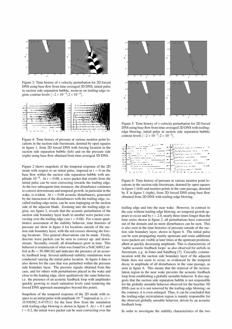
Figure 3: Time history of v-velocity perturbation for 2D forcedDNS using base flow from time-averaged 3D DNS, initial pulsein suction side separation bubble, zoom-in on trailing-edge re-gion; contour levels [−2×10⁻³;2×10⁻³].
Figure 4: Time history of pressure at various monitor point lo-cations in the suction-side freestream, denoted by open squaresin figure 1, from 2D forced DNS with forcing location in thesuction side separation bubble (left) and on the pressure side(right) using base flow obtained from time-averaged 3D DNS.
Figure 2 shows snapshots of the temporal response of the 2Dmode with respect to an initial pulse, imposed at t = 0 on thebase flow within the suction side separation bubble with am-plitude 10−8. At t = 0.08, a wave packet that results from theinitial pulse can be seen convecting towards the trailing edge.At the two subsequent time instances, the disturbance continuesto convect downstream and temporal growth, in particular in thewake, is evident. At t = 0.68 acoustic disturbances, generatedby the interaction of the disturbances with the trailing edge, so-called trailing-edge noise, can be seen impinging on the suctionside of the adjacent blade. Zooming into the trailing-edge re-gion, see figure 3, reveals that the acoustic perturbation of thesuction side boundary layer leads to another wave packet con-vecting over the trailing edge (see t = 0.68). For a more quan-titative assessment of the stability behavior, time histories ofpressure are show in figure 4 for locations outside of the suc-tion side boundary layer, with the red crosses showing the forc-ing locations. Two general observations can be made. Firstly,discrete wave packets can be seen to convect up- and down-stream. Secondly, overall, all disturbances grow in time. Thisbehavior is reminiscent of what was found for a NACA0012 air-foil at Re = 50,000 [6] and indicates the presence of an acous-tic feedback loop. Several additional stability simulations wereconducted varying the initial pulse location. In figure 4 data isalso shown for the case that was perturbed within the pressureside boundary layer. The pressure signals obtained from thiscase, and for others with perturbations placed in the wake andclose to the leading edge, show qualitatively the same behavior,i.e. the presence of an acoustic feedback loop with amplitudesquickly growing to reach saturation levels (and rendering theforced DNS approach meaningless beyond this point).
Snapshots of the temporal response of the 2D mode with re-spect to an initial pulse with amplitude 10−8 imposed at (x, y) =(0.936582, 0.473511) for the base flow from the simulationwith trailing-edge blowing is shown in figure 5. At t = 0.1 andt = 0.2, the initial wave packet can be seen convecting over the
Figure 5: Time history of v-velocity perturbation for 2D forcedDNS using base flow from time-averaged 2D DNS with trailing-edge blowing, initial pulse in suction side separation bubble;contour levels [−2×10⁻³;2×10⁻³].
Figure 6: Time history of pressure at various monitor point lo-cations in the suction-side freestream, denoted by open squaresin figure 1 (left) and monitor points in the vane passage, denotedby X in figure 1 (right), from 2D forced DNS using base flowobtained from 2D DNS with trailing-edge blowing.
trailing edge and into the near wake. However, in contrast tothe case without trailing-edge blowing, no temporal growth ap-pears to occur and by t = 2.0, nearly three times longer than thetime series shown in figure 2, all perturbations have convectedout of the domain and no more disturbances can be seen. Thisis also seen in the time histories of pressure outside of the suc-tion side boundary layer, shown in figure 6. The initial pulsecan be seen propagating mainly upstream and some additionalwave packets are visible at later times at the upstream positions,albeit at quickly decreasing amplitude. This is characteristic of‘stable acoustic feedback loops’ as also observed for airfoils infreestream, e.g. in Jones and Sandberg [7]. Crucially, commu-nication with the suction side boundary layer of the adjacentblade does not seem to occur, as evidenced by the temporaldecay in amplitude of all disturbances in the vane passage, asseen in figure 6. This means that the removal of the recircu-lation region in the near wake prevents the acoustic feedbackloop from establishing a globally unstable behavior. It also sug-gests that the suction side separation bubble is not responsiblefor the globally unstable behavior observed for the baseline 3DDNS case as it is not removed by the trailing-edge blowing; onthe contrary, it is even enlarged. Thus, it can be concluded thatthe trailing-edge recirculation region is mainly responsible forthe observed globally unstable behavior, driven by an acousticfeedback loop.
In order to investigate the stability characteristics of the two

Figure 7: Temporal development of spanwise Fourier modes ofdensity at forcing location (left) and in wake (right) obtainedusing base flow from time-averaged 3D DNS.
Figure 8: Temporal development of spanwise Fourier modes ofdensity at forcing location (left) and in wake (right) obtainedusing base flow from 2D DNS with trailing-edge blowing.
base flows discussed above with respect to three-dimensionalperturbations, three-dimensional forced DNS were conductedto study the pulse response (initial pulse at t = 0 with ampli-tude 10−8 was added to all Fourier modes k). Stability sim-ulations were conducted for several spanwise domain sizes,all producing consistent results, thus only data from calcula-tions with a spanwise extent of 0.4 axial chords are shown, us-ing a total of 8 Fourier modes. Figure 7 shows the pulse re-sponse of all spanwise Fourier modes for the case where thebase flow obtained from the 3D DNS is perturbed in each span-wise mode within the suction side separation bubble at (x, y) =(0.936582, 0.473511). At the forcing location, all mode ampli-tudes initially decay until exhibiting strong temporal growth forapproximately t > 0.2. Based on this and snapshots of the tem-poral evolution of the individual modes (not shown for brevity),and supported by the findings from the two dimensional sta-bility analysis presented above, it is conjectured that the sepa-ration bubble itself is not absolutely unstable but the underly-ing acoustic feedback loop supports the temporal growth of thethree-dimensional modes.
The temporal development of the spanwise Fourier modes in thewake of the vane, several trailing-edge thicknesses downstreamof the trailing edge, is also shown in figure 7. Temporal growthof all modes occurs earlier than farther upstream and with agreater growth rate, which supports the above suggestion thatthe recirculation region of the near wake can be considered tobe an amplifier responsible for a globally unstable behavior.
The three dimensional stability investigations were repeated forthe base flow obtained from the 2D DNS with trailing-edgeblowing with results shown in figure 8. At the forcing loca-tion in the suction side separation bubble, the amplitude of allmodes decays over time indicating that the base flow is abso-lutely stable with respect to three dimensional disturbances. Inthe wake, growth of all modes is observed from roughly t = 0.1until t = 0.25 after which the amplitudes decay again. Thus,similar to the two dimensional mode, the effect of trailing edgeblowing is the suppression of the global instability of the highermodes as a result of the removal of the near-wake recircula-tion region. All three-dimensional stability calculations wererepeated inserting the initial pulse at other locations and it wasfound that the results are independent of forcing location.
Conclusions
Time- and spanwise averaged data from DNS of a high-pressureturbine vane at engine-representative conditions were used asbase flow for multi-dimensional linear stability analysis. Fur-thermore, a 2D DNS was conducted of the same HPT vane con-figuration with trailing-edge blowing to provide an additionalbase flow without near-wake recirculation region. The multi-dimensional stability analyses were conducted by computingthe temporal pulse response of the 2D and 3D spanwise Fouriermodes with respect to both base flows.
For the case without trailing-edge blowing, the temporal pulseresponse of 2D perturbations reveals the presence of an acousticfeedback loop, with rapidly growing amplitudes. The base flowis also found to be globally unstable with respect to 3D instabili-ties, regardless of the initial perturbation location. When repeat-ing the linear stability simulations with the base flow obtainedfrom the case with trailing-edge blowing, in which the near-wake recirculation region is removed, both 2D and 3D distur-bances decay over time, independent of forcing location. Thisindicates that the trailing-edge recirculation region is largely re-sponsible for the occurrence of the acoustic feedback loop andthe rapid temporal growth of three-dimensional disturbances.We have therefore shown that trailing-edge blowing can sup-press the acoustic feedback loop.
Acknowledgements
The authors are grateful for the computing resources pro-vided by the Partnership for Advanced Computing in Europe(PRACE), “The Pawsey Supercomputing Centre” with fundingfrom the Australian Government and the Government of West-ern Australia and the UK Turbulence Consortium under EPSRCgrant EP/L000261/1.
References
[1] A. Wheeler, R. Sandberg, N. Sandham, R. Pichler,V. Michelassi and G. Laskowski, Direct Numerical Simula-tions of a High-Pressure Turbine Vane, J. Turbomachinery138, 071003 (2016).
[2] T. Arts, R. Lambert and A. W. Rutherford, Aero-ThermalInvestigation of a Highly Loaded Transonic Linear TurbineGuide Vane Cascade, von Karman Institute Technical Note,Vol. 174, Brussels, Belgium (1990).
[3] R. D. Sandberg and N. D. Sandham, Nonreflecting zonalcharacteristic boundary condition for direct numerical sim-ulation of aerodynamic sound, AIAA J. 44, 402 (2006).
[4] R. Sandberg, R. Pichler, L. Chen, R. Johnstone andV. Michelassi, Compressible Direct Numerical Simulationof Low-Pressure Turbines: Part I – Methodology, J. Turbo-machinery 137, 051011 (2015).
[5] R. D. Sandberg, Numerical investigation of turbulent super-sonic axisymmetric wakes, J. Fluid Mech. 702, 488 (2012).
[6] L. E. Jones, R. Sandberg and N. Sandham, Stability andreceptivity characteristics of a laminar separation bubble onan aerofoil, J. Fluid Mech. 648, 257 (2010).
[7] L. E. Jones and R. Sandberg, Numerical analysis of tonalairfoil self-noise and acoustic feedback-loops, J. Sound andVibration 330, 6137 (2011).