the proper orthogonal decomposition in the analysis of...
TRANSCRIPT

18th Australasian Fluid Mechanics Conference Launceston, Australia 3-7 December 2012
The Proper Orthogonal Decomposition in the Analysis of the wake behind a Foamed and a Finned Circular Cylinder
M. Khashehchi1, K. Hooman1, A. Ooi3 and T. Roesgen2
1Queensland Geothermal Energy Centre of Excellence The University of Queensland, QLD 4072, Australia 2Institute of Fluid Dynamics, ETH Zurich, 8092 Zurich, SWITZERLAND
3Department of Mechanical Engineering, The University of Melbourne, VIC 3010, Australia
Abstract
Particle Image Velocimetry (PIV) has been carried out to investigate the wake region behind a foamed and a finned cylinder. The purpose of this analysis is to develop one- and two-point correlations and to investigate the flow characteristics for these two cases. The experiments are conducted for two Reynolds numbers (based on the mean air velocity and the cylinder diameter) 2000 and 8000. Two dimensional results of planar PIV reveal the important aspects of the local flow features of the circular finned and foamed cylinders. These include turbulent boundary layer development over the surface and a delayed separation of the flow resulting in a smaller wake size in each case. The application of Proper Orthogonal Decomposition (POD) to the PIV velocity fields of the two cylinder types is also discussed. The POD computed for the measured velocity fields for both cases shows that the first two spatial modes contain most of the kinetic energy of the flow irrespective to the cylinder type. These two modes are also responsible for the large-scale coherence of the fluctuations. For two different cylinder types, the first four eigenmodes of the flow field were calculated and their structures were analyzed. The first four eigenmodes reveal the details about the global mean flow structure, with the large-scale structure being mainly related to the most energetic flow motion.
Introduction
During the last few decades, the mechanism of vortex shedding structures and the structure of the wake created behind circular cylinders have been investigated in a wide variety of studies. Concern here is motivated not only by the desire to understand the fundamental characteristics of cylinder aerodynamics, but also by its direct impact on engineering applications such as heat exchangers. The ever-growing experimental capabilities such as PIV or other laser diagnostic methods enable us to acquire a better understanding of details of the flow structures behind the cylinder and, consequently, the induced turbulence in the wake. Formation of coherent structures is normally observed when the flow passes the cylinder. These structures then will shed and be advected downstream with the flow, and are responsible for wake characteristics such as the shedding frequencies and mixing properties. There have been numerous experiments conducted to examine the flow around circular cylinders in cross-flow. Roshko [1] defined the range of critical Reynolds numbers, which defines the fundamental problem for the scale model testing of curved structures in low speed wind tunnels. However, the concept of controlling the flow over circular cylinders is not yet fully understood, in spite of many studies on the effect of surface
roughness on cylinders in the past. Bearman and Harvey [2] examined dimpled surfaces, while roughness on a cylinder was tested by Szechenyi [3]. Both of these studies showed that the pressure distribution around the cylinder could be altered through the addition of a roughness pattern. On the other hand, very limited research has been done looking at the application of attached finned and foamed cylinders in flow control strategies and heat transfer efficiency. Whilst fins are considered as vortex-spoilers as they disturb the shed vortices, making them less coherent and three dimensional (Zdravkovich [10]), several studies of vortex shedding of finned-cylinders show that the vortex shedding frequency is well correlated with the cylinder effective diameter, which is based on the projected frontal area of the cylinder (Mair et al. [11], Hamakawa et al. [12]). Several unresolved issues still need to be investigated in order to improve our fundamental understanding of the effect of fins on the turbulence behind the cylinder. Moreover, the role of the foam on the structures behind the cylinder seems to be different and has not been studied before. As mentioned, in contrast to the extensive consideration that has been devoted to the flow around bare cylinders, the flow structures around the finned and foamed cylinders and the characteristics of the wake behind such surfaces has received relatively little attention. In such cases, the flow structure is completely different from that of the bare cylinder located in a uniform flow. One effective method for investigating complex flows containing large-scale organized structures and turbulent structures is POD (Proper Orthogonal Decomposition) analysis (Lumley et al. [14]). The POD analysis can extract flow pattern based on the consideration of kinetic energy. It can be used to investigate the dominant coherent structure from instantaneous turbulent flow fields. In this study, we use the POD method to clarify the dominant flow structure of the near wake behind the three cylinder types of interest in order to make a comparison to the flow structures in the presence of different obstacle geometries. The POD analysis was performed for an ensemble of instantaneous velocity fields obtained by PIV technique at each cylinder type.
Experimental Setup
All experiments were carried out in an open circuit low-speed wind tunnel equipped with a centrifugal suction fan, a settling chamber comprising one screen, followed by a honeycomb, two more screens, a 5.5:1 contraction and working sections. The test section is 460 mm high, 460 mm wide and 1200 mm in length (figure 1 top). Except for the floor of the wind tunnel in the testing area which is fabricated from ordinary wood, all other sides are made of Plexiglas which allows a clear view of the

working section from either side. Turbulence intensity of the flow in the wind tunnel was measured using PIV analysis in a region approximately 500 mm downstream from the contraction, which is the location of the lowest turbulence intensity within the working section (Soria [4]). All the experiments are conducted in this particular region. The imaged region measured 92 mm in the downstream direction and 68 mm in the cross stream direction. The measured turbulence intensity over a range of velocities from 1 m/s to 4 m/s was less than 3%. It is noted, however, that other techniques such as Hot-Wire Anemometry, would give a more accurate assessment of turbulence intensity, as PIV tends to overestimate this value (Westerweel [8]).
Figure 1. Experimental set up. The Nd:YAG laser is located above the Field of view on top of the wind tunnel, the camera faces the laser light sheet. Schematic of different cylinder types are also shown.
To determine the effect of each experimental parameter on the turbulent structures created behind the cylinder, the experiment for each cylinder type was repeated for two Reynolds numbers ReD =2000 and 8000 where the diameter D is 30 mm and the free stream velocity varies from 1 to 4 m/s. The cylinder axis is oriented horizontally in the middle of the test section. The finned-cylinder used in this work was manufactured from solid aluminium with 60 mm length and 30 mm diameter. In addition, the finned cylinder fitted with tapered fins with 0.4 mm thickness, 4.5 mm spacing and 16 mm height. The foamed cylinder, shown in figure 1-b, consists of ligaments forming a network of inter-connected cells. The cells are randomly oriented and are mostly homogeneous in size and shape. Pore size may be varied from approximately 0.4 mm to 3 mm, and the effective density from 3% to 15% of a solid of the same material. In this study, 6 mm thickness of the present aluminium foamed structure is attached to the above-mentioned bare cylinder in order to comparatively study the turbulence behind the cylinder. The Field Of View (FOV) of size 3D in the streamwise direction and
of size 2D in the cross stream direction (92×68 mm2) was chosen for PIV imaging, starting from 0.5D downstream the cylinder, and is shown in figure 1-b. Images acquired at this position capture the wake flow behind the objects as well as the first and second coherent detached structures shedding to the main flow. The particles used for PIV imaging were generated by a pressure droplet generator with oil liquid as the droplet constituent. The illumination was delivered by a Nd:YAG PIV laser (Dantec-130 mJ), which could provide two laser pulses required for PIV analysis. The scattered light from the seeded particles was recorded by a CCD camera with 1380×1024 pixels which was fitted with a 50 mm Nikon lens with f-stop set at 4, resulting in a magnification of 0.2. Timing of the laser and camera was controlled via Dantec software included in the package. The number of samples in each experiment was 1000 image pairs. The present single exposed image acquisition experiments were designed for a two-pass MCCDPIV analysis. The first pass used an interrogation window of 64 pixels, while the second pass used an interrogation window of 32 pixels with discrete interrogation window offset to minimize the measurement uncertainty (Westerweel [8]). The sample spacing between the centers of the interrogation windows was 16 pixels. The analysis returned 83×63 velocity vectors within the FOV. A sample of the instantaneous velocity field derived from the PIV data in the turbulent region of the bare cylinder at ReD=4000 is shown in figure 2, bottom. Figure 2 (top) also shows the PIV results of the flow over the bare cylinder at ReD=3900 (Philippe et al. [13]). As can be seen, the fluctuations of the structures behind the cylinder of both cases are very similar and the figure could be used for validation purposes. The uncertainty relative to the maximum velocity in the velocity components at the 95% confidence level for these measurements is 0.3%. The uncertainty was estimated taking into account the uncertainty in the sub-pixel displacement estimator of 0.1 pixels, and the uncertainty in the laser sheet alignment of 1%. Other uncertainty sources including those due to timing, particle lag, seeding uniformity, and calibration grid accuracy were minor.
Figure 2. The instantaneous velocity field behind the bare-cylinder, present results (bottom) and PIV analysis by Philippe et al. [13] (top)
(a)
(b)
Results
The two Reynolds numbers chosen for comparison were 2000 and 8000. Due to the high flow velocity (relative to the Kolmogorov velocity scale) and the limited FOV, it was not possible to obtain images of the separated wake region over the entire range of flow rates available in the wind tunnel. It should be noted that the FOV does not allow seeing the flow structures that occur further downstream; however the near-wake flow structures are the main focus of this study. Indeed, 1000 image pairs were recorded for analysis at all Reynolds numbers for each of the three objects (bare, fin and foam). Figure 3 presents the mean velocity field superimposed with the mean streamline velocities for two different cylinder types, the finned and foamed cylinders, at the two Reynolds numbers 2000 and 8000. The near-wake vortex structures are coherent, well-defined and three dimensional (Roshko [1]). Comparing the mean streamwise velocity field U between the finned and foamed cylinder types at the two mentioned Reynolds numbers (figure 3) with the previous case shows a dramatic change in the patterns of the velocity contours within the wake region. This may be as a result of the geometry of the attached fins in comparison with the foamed cylinder, which could result in a wake of different size behind the cylinder. While the foam’s body structure represents an obstacle to the incident flow, the plane of the fins is parallel to the streamwise direction and generate streamwise vorticity. Thus, the size of the wake behind the foamed cylinder is considerably larger than that of the finned case.
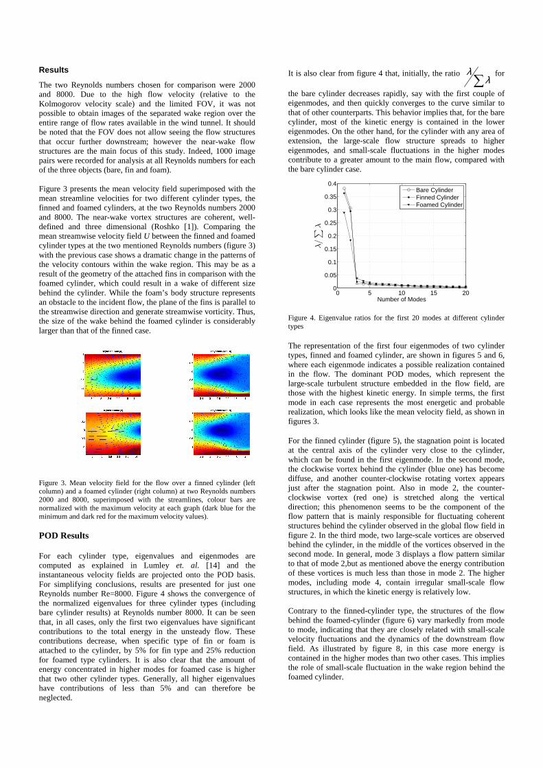
Figure 3. Mean velocity field for the flow over a finned cylinder (left column) and a foamed cylinder (right column) at two Reynolds numbers 2000 and 8000, superimposed with the streamlines, colour bars are normalized with the maximum velocity at each graph (dark blue for the minimum and dark red for the maximum velocity values). POD Results For each cylinder type, eigenvalues and eigenmodes are computed as explained in Lumley et. al. [14] and the instantaneous velocity fields are projected onto the POD basis. For simplifying conclusions, results are presented for just one Reynolds number Re=8000. Figure 4 shows the convergence of the normalized eigenvalues for three cylinder types (including bare cylinder results) at Reynolds number 8000. It can be seen that, in all cases, only the first two eigenvalues have significant contributions to the total energy in the unsteady flow. These contributions decrease, when specific type of fin or foam is attached to the cylinder, by 5% for fin type and 25% reduction for foamed type cylinders. It is also clear that the amount of energy concentrated in higher modes for foamed case is higher that two other cylinder types. Generally, all higher eigenvalues have contributions of less than 5% and can therefore be neglected.
It is also clear from figure 4 that, initially, the ratio ∑λ
λ for
the bare cylinder decreases rapidly, say with the first couple of eigenmodes, and then quickly converges to the curve similar to that of other counterparts. This behavior implies that, for the bare cylinder, most of the kinetic energy is contained in the lower eigenmodes. On the other hand, for the cylinder with any area of extension, the large-scale flow structure spreads to higher eigenmodes, and small-scale fluctuations in the higher modes contribute to a greater amount to the main flow, compared with the bare cylinder case.
Figure 4. Eigenvalue ratios for the first 20 modes at different cylinder types The representation of the first four eigenmodes of two cylinder types, finned and foamed cylinder, are shown in figures 5 and 6, where each eigenmode indicates a possible realization contained in the flow. The dominant POD modes, which represent the large-scale turbulent structure embedded in the flow field, are those with the highest kinetic energy. In simple terms, the first mode in each case represents the most energetic and probable realization, which looks like the mean velocity field, as shown in figures 3. For the finned cylinder (figure 5), the stagnation point is located at the central axis of the cylinder very close to the cylinder, which can be found in the first eigenmode. In the second mode, the clockwise vortex behind the cylinder (blue one) has become diffuse, and another counter-clockwise rotating vortex appears just after the stagnation point. Also in mode 2, the counter-clockwise vortex (red one) is stretched along the vertical direction; this phenomenon seems to be the component of the flow pattern that is mainly responsible for fluctuating coherent structures behind the cylinder observed in the global flow field in figure 2. In the third mode, two large-scale vortices are observed behind the cylinder, in the middle of the vortices observed in the second mode. In general, mode 3 displays a flow pattern similar to that of mode 2,but as mentioned above the energy contribution of these vortices is much less than those in mode 2. The higher modes, including mode 4, contain irregular small-scale flow structures, in which the kinetic energy is relatively low. Contrary to the finned-cylinder type, the structures of the flow behind the foamed-cylinder (figure 6) vary markedly from mode to mode, indicating that they are closely related with small-scale velocity fluctuations and the dynamics of the downstream flow field. As illustrated by figure 8, in this case more energy is contained in the higher modes than two other cases. This implies the role of small-scale fluctuation in the wake region behind the foamed cylinder.
0 5 10 15 200
0.05
0.1
0.15
0.2
0.25
0.3
0.35
0.4
Number of Modes
λ/∑
λ
Bare CylinderFinned CylinderFoamed Cylinder

Figure 5. Visualization of the four eigenmodes for finned cylinder at
Reynolds number 8000
For mode 1, the stagnation point is located on the cylinder major axis in a distance at least 3 times farther away from the cylinder compared to the bare cylinder. The presence of a double-vortex at the centre of the wake region causes the stagnation point to shift downward. It is surprising to see that another stagnation point is created in the wake region almost exactly where the finned-cylinder stagnation point would have been. Perhaps, the transition between the uniform flow over the cylinder and the two vortices shown in mode 1 creates a singularity in this region. Unlike the structures observed in the second mode of finned case, mode 2 shows just one counter-rotating vortex, situated symmetrically in the centre of the wake region. Mode 2 shows an almost symmetric vortex structure in the near-wake region. The size of the vortex in mode 2 and 3 in foamed cylinder is much larger than those in finned cylinder case, as expected. Therefore, modes 2 and 3 seem to be responsible for the highly irregular turbulence pattern in this large wake region. The combined effects of these two modes are to provoke fluctuations of the stagnation point in the flow. Mode 4 displays a more complicated flow structure; it contains two vortices in the early region of FOV, and a series of small-scale vortices downstream that are indistinct due to vortex breakdown.
Figure 6. Visualization of the four eigenmodes for foamed cylinder at Reynolds number 8000
Conclusions
PIV measurements have been made in the low speed wind tunnel facility at the School of Mechanical and Mining Engineering at the University of Queensland, Brisbane, Australia. A 2D PIV system manufactured by Dantec Dynamics was successfully utilized to perform measurements in three different types of turbulent flow fields; behind a finned and foamed cylinder. The
measurements also covered different Reynolds numbers ranging from 2000 to 8000. In addition to the statistical comparison between the flow structures of the two cylinder types, POD analysis was used to investigate the eigenvalues and eigenmodes of the flow behind the aforementioned cylinders. The first four eigenmodes of the near wake behind the bare cylinder clearly showed the existence of large-scale coherent structures at different energy levels. The majority of the kinetic energy was concentrated in the large-scale motions in the first and second eigenmodes. The same pattern was observed in the structures of the second and third modes of the finned cylinder. However, in comparison with the finned cylinder eigenmodes figures, the coherent structures of the second and third modes of the foamed cylinder show different pattern with strong vortices. The higher eigenmodes provided more details on small-scale structures, most of which were located in the region of the mean velocity field exhibiting lower turbulence kinetic energy levels, which are more powerful in the case of foamed cylinder.
References
[1] Roshko A. Experiments on the Flow past a Circular Cylinder at Very High Reynolds. Journal of Fluid Mechanics, Vol. 10, No. 1, pp 345-356, 1961.
[2] Bearman P.W, Harvey J.K, Control of Circular Cylinder Flow by the Use of Dimples. AIAA Journal, Vol. 31, No. 10, pp 1753-1756, 1993.
[3] Szechenyi E. Supercritical Re Simulation for Two-Dimensional Flow over Circular Cylinders. Journal of Fluid Mechanics, Vol. 701, pp 529-542, 1975.
[4] Soria J, The effects of transverse plate surface vibrationson laminar boundary layer flow and convective heat transfer. PhD Thesis, The University of Western Australia, 1988.
[5] Soria J, Digital cross-correlation particle image velocimetry measurements in the near wake of a circular cylinder. In International Colloquium on Jets, Wakes and Shear Layers, Melbourne, Australia, 1994.
[6] Soria J, An investigation of the near wake of a circular cylinder using a video-based digital cross-correlation particle image velocimetry technique. Experimental Thermal and Fluid Science, Vol. 12, pp 221-233, 1996a
[7] Soria J, An adaptive cross-correlation digital PIV technique for unsteady flow investigations. In A.R. Masri and D.R. Honnery, editors, Proc. 1st Australian Conference on Laser Diagnostics in Fluid Mechanics and Combustion, pp 29-48, Sydney, NSW, Australia, 1996b.
[8] Westerweel J, Fundamentals of digital particle image velocimetry. Meas Sci Technol, Vol. 8, pp 1379-1392, 1997.
[9] Hart D, The elimination of correlation error in piv processing. In Proceedings of 9th International Symposium of Applications of Laser Techniques to Fluid Mechanics, Lisbon, Portugal,1998
[10] Zdravkovich M.M., Review and classification of various aerodynamic and hydrodynamicmeans for suppressing vortex shedding. Journal of Wind Engineering and Industrial Aerodynamics, Vol. 7, pp 145-189, 1981.
[11] Mair W.A., Jones P.D.F., Palmer R.K.W., Vortex shedding from finned tubes. Journal of Sound and Vibration, Vol. 39, pp 293-296, 1975.
[12] Hamakawa H., Fukano T., Nishida E., Aragaki M., Vortex shedding from a circular cylinder with fin. AIAA Aeroacoustics Conference, Maastricht, Paper AIAA-2001-2215, 2001.
[13] Philippe P., Johan C., Dominique H., Eric L., Experimental and numerical studies of the flow over a circular cylinder at Reynolds number 3900, Physics of Fluids, Vol. 20, 085101, 2008.
[14] Lumley J. L., Holmes P. and Berkooz G., The proper orthogonal decomposition in the analysis of turbulent flows, Ann. Rev. Fluid Mech. Vol. 25, pp 539–575, 1993.