non-destructive evaluation of railway track using ground penetrating radar
TRANSCRIPT

7/23/2019 Non-Destructive Evaluation of Railway Track Using Ground Penetrating Radar
http://slidepdf.com/reader/full/non-destructive-evaluation-of-railway-track-using-ground-penetrating-radar 1/4
U.S. DepartmentO
f Transportation
Federal Railroad
dministration
RR05-06October 2005
Non-Destructive Evaluation of Railway Track UsingGround Penetrating Radar
SUMMARY
The Federal Railroad Administration (FRA) Office of Research and Development sponsored a study
under the Track and Structures Program for evaluating railway track conditions using ground-penetratingradar (GPR). The track conditions targeted by the GPR research contribute to its overall performanceand the safety of railway operations including the rate of track geometry deterioration, track bucklingpotential, and overall track support conditions as covered by the FRA Railway Accident IncidentReporting Systems (RAIRS) train accident cause codes T101-T108, T109, and T001, respectively (FRA,1997). GPR can provide a rapid, non-destructive inspection for evaluating railway track substructureintegrity. As shown in Figure 1, the equipment is non-contact and allows data collection at normal vehicletrack speed. GPR provides continuous top-of-rail measurements of substructure layer conditions, withthe potential to measure the layer thickness, water content, and density of the substructure components(ballast, sub ballast, subgrade). GPR is also capable of observing trapped water from poor drainage, softsubgrade due to high water content and related deformation, and is potentially capable of distinguishingfouled ballast from clean ballast. The study shows that GPR can quantify the thickness, lateral, andlongitudinal extent of substructure layers. GPR can provide useful profiles of the track substructureshowing variation in condition and depth along and across the track, indicative of differences in trackperformance.
Figure 1. GPR Test Equipment Deployed for Track Inspection

7/23/2019 Non-Destructive Evaluation of Railway Track Using Ground Penetrating Radar
http://slidepdf.com/reader/full/non-destructive-evaluation-of-railway-track-using-ground-penetrating-radar 2/4
US Department of transportation
Federal Railroad Admin istration Research Results RR05-06
Page 2
BACKGROUND
The goal of the study has been to develop GPRsystems and procedures for determining tracksubstructure conditions such as layer
thicknesses and zones of trapped water. Thework was completed in 3 phases. Phase 1 of thestudy consisted of an initial series of laboratoryand field measurements. Phase 2 focused onimproving the radar equipment and techniquesand demonstrating the benefit of obtainingmeasurements at multiple positions across thetrack. Phase 3 consisted of automating datacollection procedures and additional field-testingto verify processing techniques and algorithms.This document describes the cumulativeaccomplishments of this program.
GROUND PENETRATING RADAR (GPR)
GPR transmits pulses of radio energy into thesubsurface and receives the returning pulsesthat have reflected off interfaces betweenmaterials with different electromagneticproperties. GPR antennas are moved across atest area (Figure 2a) recording a continuousseries of radio pulses (Figure 2b), producing aprofile of the subsurface (Figure 2c). The rawprofile is distorted due to antenna positiongeometry, orientation, and material properties,but data processing techniques are used to limit
the distortion.
Transmit An tenna
Receive Ant enna
Air
Ballast
Subballast
Subgrade
Figure 2. GPR Profile Generation
The key material properties are the dielectricpermittivity, the magnetic permeability, and theelectrical conductivity. The dielectric permittivity dominantly controls the velocity of
electromagnetic wave propagation and is afunction of the density, water content, and typeof material. The magnetic permeability alsocontrols velocity, and is commonly neglected(assumed to be the value of air), though it may
be important when iron-bearing materials arepresent such as some slag and iron ore fouling.The electrical conductivity is the main electricalparameter controlling the depth of investigation,and is the ability of the material to conductelectrical current, which is affected by theamount of water in the track.
DATA COLLECTION AND ANALYSIS
GPR provides a continuous characterization ofthe track substructure, quickly locating areas ofpotential trouble for further investigation or
maintenance. GPR has the ability to provide arapid, non-destructive evaluation of substructurecondition indicators and can be used to providenumerical data for development of substructurecondition indices (Hyslip, et al, 2003).
Material and moisture variation within the tracksubstructure are easily detected using GPR.Water possesses a high dielectric permittivitycompared to the other materials in thesubstructure and produces a strong effect on theGPR profiles. The open voids in clean ballastalso produce a strong effect on GPR data. The
voids in clean ballast may cause diffraction ofthe GPR pulse at the particle interfaces allowingthe relatively coarse-grained ballast layer to berecognizable from the comparatively finer-grained subballast layers. The variations in theGPR profile may allow fouled ballast to beidentified, since the voids in fouled ballast arefilled with finer particles, limiting diffraction.
Ampli tude
T i m e
Surface
Top of Subballast
Top of Subgrade
a b c
To verify and calibrate the GPR data, crosstrenches were excavated and the substructurevariations correlated with GPR data. Figure 3shows a typical GPR image along a 500 ft (150
m) section of track. Figure 3 also shows photosof the cross trenches that were excavated andlogged for calibration of the GPR data. Depthsto key substructure layers were measured in thecross trenches and used with travel times fromthe radar data to determine average velocities.The velocities were used to calculate thematerial properties values such as dielectricpermittivity.

7/23/2019 Non-Destructive Evaluation of Railway Track Using Ground Penetrating Radar
http://slidepdf.com/reader/full/non-destructive-evaluation-of-railway-track-using-ground-penetrating-radar 3/4
US Department of transportation
Federal Railroad Admin istration Research Results RR05-06
Page 3
Track substructure conditions can vary overshort distances and across the track. Toaccount for variations from center of track toeither shoulder, GPR antennas collected datafrom all 3 locations. In Figure 4, trapped water
near a grade crossing resulted in poor trackperformance and coincided with lack of lateraldrainage. Using GPR, the zone of trappedwater was targeted and drainage enhancementstargeting only the problem area could beidentified, as shown on the westside image.
Figure 3. GPR Data with Cross-Trench
Figure 4. GPR Profiles Along Shoulders andTrack Center
IMPLEMENTATION
To ensure that GPR technology providesoperationally significant insight to track safetyconditions in a timely manner, automated dataprocessing is required. Furthermore, a level ofautomatic interpretation is required for railway
applications due to the many miles of surveywith condition assessment required in near real-time. Follow-on phases of this work are to utilizethe identified strategies to develop robustautomated data interpretation.
GPR provides insight to many of the significantrailway track deterioration modes and symptomsincluding:
• Trapped water and/or weak substructureconditions resulting in unstable track or poortrack geometry,
• Inadequate substructure layer thicknessresulting in weak track or in track notmeeting design criteria,
• Variable track conditions resulting invariations in longitudinal track support withthe potential for repeated track geometry
defects,
The range of track condition indicators results ina variety of potentially substandard trackcondition diagnoses from GPR. Due to therange of potential defects, a variety of GPRbased track condition indices have beendeveloped including:
• A layer thickness variation index,
• A ballast pocket index,
• A layer roughness index, and
• A subballast-thinning index.
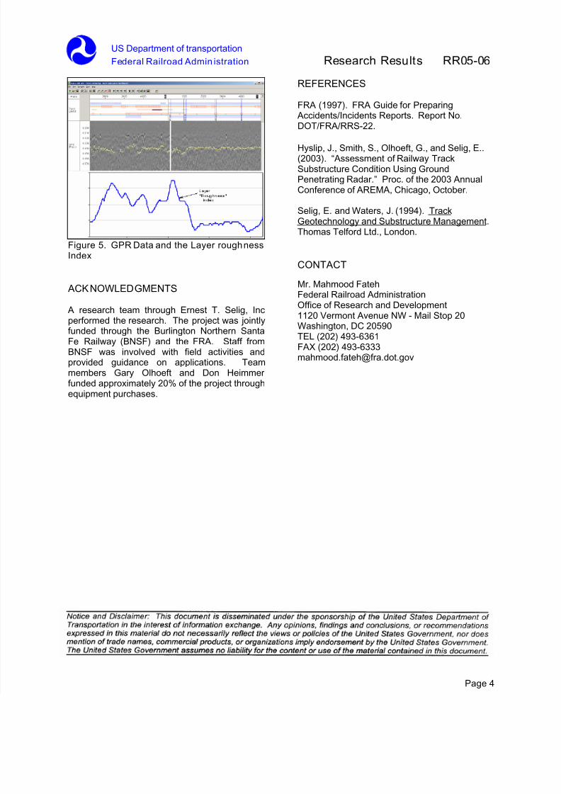
The various indices have been correlated withfield conditions and poor track geometry. Figure5 presents a set of GPR data along with thelayer roughness index to capture layer variation.Changes in track support and layer thicknesscan result in track geometry defects, which tendto occur repeatedly; a phenomenon oftentermed track memory (Selig and Waters, 1994).
CONCLUSIONS
GPR data provides unique insight to track
substructure conditions affecting track support,track stability and overall track safety. Analysisof the data in near real-time is required to makedecisions affecting safety and operations of thetrack. Current research has demonstrated thepotential of the technology; howeverimplementation and automation of the identifiedtrack conditions diagnosis algorithms requireadditional research.
7/23/2019 Non-Destructive Evaluation of Railway Track Using Ground Penetrating Radar
http://slidepdf.com/reader/full/non-destructive-evaluation-of-railway-track-using-ground-penetrating-radar 4/4
US Department of transportation
Federal Railroad Admin istration Research Results RR05-06
Page 4
Figure 5. GPR Data and the Layer roughnessIndex
ACKNOWLEDGMENTS
A research team through Ernest T. Selig, Incperformed the research. The project was jointlyfunded through the Burlington Northern SantaFe Railway (BNSF) and the FRA. Staff fromBNSF was involved with field activities andprovided guidance on applications. Teammembers Gary Olhoeft and Don Heimmerfunded approximately 20% of the project throughequipment purchases.
REFERENCES
FRA (1997). FRA Guide for Preparing Accidents/Incidents Reports. Report No.DOT/FRA/RRS-22.
Hyslip, J., Smith, S., Olhoeft, G., and Selig, E..(2003). “Assessment of Railway TrackSubstructure Condition Using GroundPenetrating Radar.” Proc. of the 2003 AnnualConference of AREMA, Chicago, October.
Selig, E. and Waters, J. (1994). TrackGeotechnology and Substructure Management.Thomas Telford Ltd., London.
CONTACT
Mr. Mahmood FatehFederal Railroad AdministrationOffice of Research and Development1120 Vermont Avenue NW - Mail Stop 20Washington, DC 20590TEL (202) 493-6361FAX (202) [email protected]