ground penetrating radar gpr -
TRANSCRIPT

RD1000™
Operation Manual l Issue 1 l May 2008
Portable Ground Penetrating Radar System
� RD1000™ Operation Manual
Preface
Before you begin
Thank you for your interest in Radiodetection’s RD1000™ ground penetrating radar system.
Please read this operation manual before attempting to use the RD1000™ system.
Radiodetection products, including this manual, are under continuous development. The information contained within is accurate at time of publication; however the RD1000™, this manual and all its contents are subject to change.
Radiodetection Limited reserves the right to modify the product without notice and some product changes may have taken place after this user manual was published.
Contact your local Radiodetection dealer or visit www.radiodetection.com for the latest information about the RD1000™, including this manual and other product literature.
Important notices
General
This instrument, or family of instruments, will not be permanently damaged by reasonable electrostatic discharge and has been tested in accordance with IEC 801-�. However, in extreme cases temporary malfunction may occur. If this happens, switch off, wait and switch on again. If the instrument still malfunctions, disconnect the batteries for a few seconds.
Safety
This equipment should be used by fully qualified and trained personnel only.
This equipment is NOT approved for use in areas where hazardous gases may be present.
RD1000™ Operation Manual �
Training
Radiodetection provides training services for most Radiodetection products. Our qualified instructors will train equipment operators or other personnel at your preferred location or at Radiodetection headquarters.
For more information go to www.radiodetection.com or contact your local Radiodetection representative.
Trademarks
RD1000™ is a trademark of Radiodetection LTD, all rights reserved.
Copyright Statement
This manual is Copyright © �008 Radiodetection LTD. All rights reserved. Radiodetection LTD is a subsidiary of SPX Corporation.
This manual may not be copied, reproduced or sold in whole or in part without expressed written permission by Radiodetection Ltd. Please direct all copyright and publishing queries to you local Radiodetection representative.
Table of contents
Preface 2Before you begin �
Important notices �General �
Safety �
Training �
Trademarks �
Copyright Statement �
Section 1 Introduction 61.1 About this manual 6
1.� About the RD1000™ 6
Section 2 System Assembly 7Section 3 Getting Started 12�.1 Using the Display Unit 1�
�.� System Settings Screen 1��.�.1 Scan 1�
�.�.� Language 1�
�.�.� Units 14
�.�.4 Scale 14
�.�.5 Date 15
�.�.6 Time 15
�.�.7 Power Off 15
�.�.8 System Information 15
�.� Scanning Screen 16
�.4 Locating screen 17�.4.1 Locating Cursor 17
�.4.� Soil Type 18
�.4.� Identifying Air Wave Reflections ��
�.5 Image Settings Screen ���.5.1 Scan ��
�.5.� Clear Image ��
�.5.� Color �4
�.5.4 Gain �5
�.5.5 Filter �6
�.5.6 Depth �7
�.5.7 Quit �7
�.6 Changing the Date and Time �8
�.7 Screen icons �9�.7.1 Systems settings menu �9
�.7.� Locating screen menu �0
�.7.4 Date and time menus �1
Section 4 Surveying Techniques 324.1 Cross and mark ��
4.� Limitations ��
Section 5 Troubleshooting 345.1 Power �4
5.� System Communications �5
5.� System Overheating �5
5.4 Display Unit Problem �6
5.5 Test Line �6
5.6 Contacting the Vendor for Service �6
Section 6 Care and Maintenance 376.1 Battery Care �7
6.� Cable Care �8
6.� Skid Pad �9
6.4 Odometer �9
Appendix A 40GPR Emissions, Interference and Regulations 40
FCC Regulations 40Part 15 – User Information 40
Operating Restrictions 41
FCC Interpretation of Operation Restrictions issued July 1�, �00�
41
FCC Permitted Mode of Usage 4�
GPR Use Coordination 4�
FCC Ground Penetrating Radar Coordination Notice 44
ETSI Regulations for the EC 44
6 RD1000™ Operation Manual
Section 1 Introduction
1.1 About this manual
This manual provides cable and pipe locators with comprehensive operating instructions for the RD1000™ ground penetrating radar system. Before operating the RD1000™ system it is very important that you read this manual, noting all safety warnings and procedures.
Following is an overview of the RD1000™ System and a brief introduction to RD1000™ and ground penetrating radar technology.
In this rest of this manual you will find assembly instructions (Section �), a getting started guide (Section �) and an introductory guide to cable and pipe surveying techniques (Section 4). Also included is a troubleshooting guide in Section 5.
1.2 About the RD1000™
The RD1000™ is a ground penetrating radar system that allows the user to see almost any underground feature. Unlike a traditional locator, the RD1000™ uses radar technology (specifically in the UHF/VHF frequencies) and produces a visual map with characteristic cone-shaped images. The main advantage of this technology is that the RD1000™ can see non-conductive materials including plastic pipes.
The integrated digital signal processor (DSP) analyzes the resulting image map to give the operator information on depth. The unique ability to see a pipe or cable in its topographical context makes the RD1000™ ideal for locating and excavating utilities.
RD1000™ Operation Manual 7
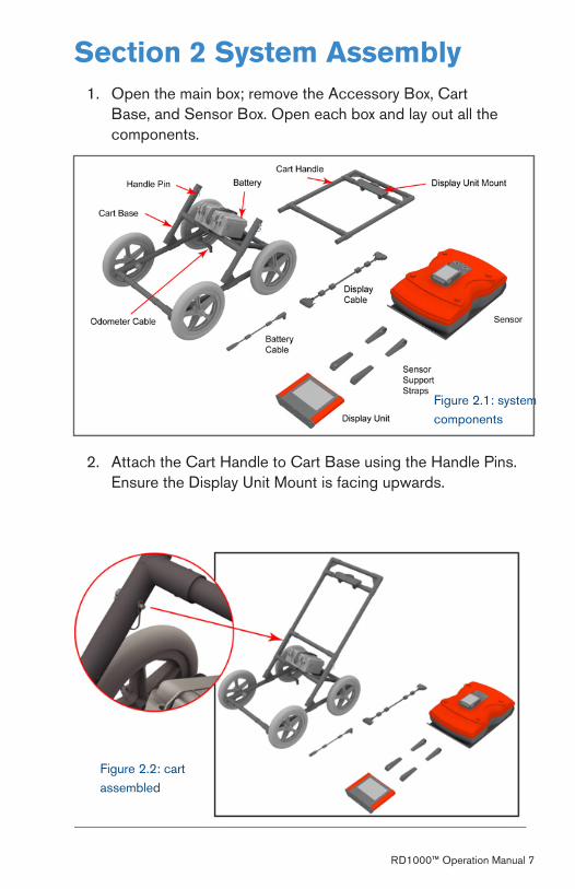
Section 2 System AssemblyOpen the main box; remove the Accessory Box, Cart Base, and Sensor Box. Open each box and lay out all the components.
1.
Figure �.1: system components
Attach the Cart Handle to Cart Base using the Handle Pins. Ensure the Display Unit Mount is facing upwards.
�.
Figure �.�: cart assembled

8 RD1000™ Operation Manual
Attach the Sensor to the Cart using the Sensor Support Straps. Ensure the Sensor is oriented the correct way with the connections toward the back of the Cart. Using the Sensor Support Straps, adjust the height of the Sensor so it’s 1-� cm (1/� – ¾ inch) above the ground.
�.
Figure �.�: sensor box installed
RD1000™ Operation Manual 9
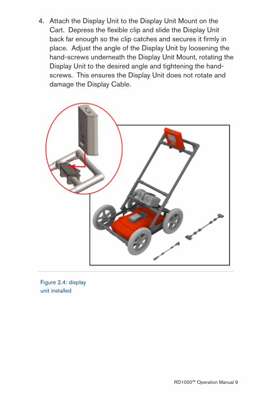
Figure �.4: display unit installed
Attach the Display Unit to the Display Unit Mount on the Cart. Depress the flexible clip and slide the Display Unit back far enough so the clip catches and secures it firmly in place. Adjust the angle of the Display Unit by loosening the hand-screws underneath the Display Unit Mount, rotating the Display Unit to the desired angle and tightening the hand-screws. This ensures the Display Unit does not rotate and damage the Display Cable.
4.
10 RD1000™ Operation Manual
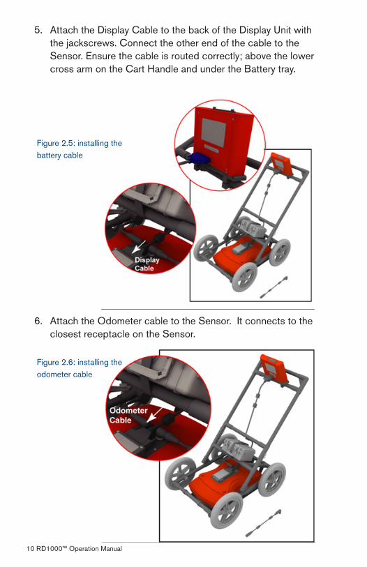
Attach the Display Cable to the back of the Display Unit with the jackscrews. Connect the other end of the cable to the Sensor. Ensure the cable is routed correctly; above the lower cross arm on the Cart Handle and under the Battery tray.
5.
Figure �.5: installing the battery cable
Attach the Odometer cable to the Sensor. It connects to the closest receptacle on the Sensor.
6.
Figure �.6: installing the odometer cable
RD1000™ Operation Manual 11
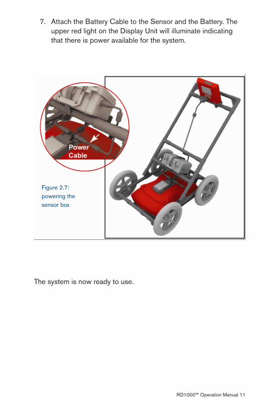
Attach the Battery Cable to the Sensor and the Battery. The upper red light on the Display Unit will illuminate indicating that there is power available for the system.
7.
Figure �.7: powering the sensor box
The system is now ready to use.
1� RD1000™ Operation Manual
Section 3 Getting Started
3.1 Using the Display Unit
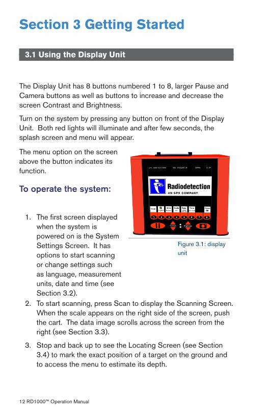
The Display Unit has 8 buttons numbered 1 to 8, larger Pause and Camera buttons as well as buttons to increase and decrease the screen Contrast and Brightness.
Turn on the system by pressing any button on front of the Display Unit. Both red lights will illuminate and after few seconds, the splash screen and menu will appear.
Figure �.1: display unit
The menu option on the screen above the button indicates its function.
To operate the system:
The first screen displayed when the system is powered on is the System Settings Screen. It has options to start scanning or change settings such as language, measurement units, date and time (see Section �.�).
1.
To start scanning, press Scan to display the Scanning Screen. When the scale appears on the right side of the screen, push the cart. The data image scrolls across the screen from the right (see Section �.�).
Stop and back up to see the Locating Screen (see Section �.4) to mark the exact position of a target on the ground and to access the menu to estimate its depth.
�.
�.

RD1000™ Operation Manual 1�
When you push the cart forward again and reach the point where you originally stopped and backed up, the system will automatically start scanning again. Or press Clear Screen to start fresh.
At any time press the Pause button to change Depth, Color, Gain etc. using the Image Settings Screen (see Section �.5) then press Scan (or Pause again) to continue.
If the Display Unit has Compact Flash disk, pressing the Camera button saves the current screen image to the Compact Flash. Later, transfer images to a PC for re-plotting and printing.
3.2 System Settings Screen
4.
5.
6.
Figure �.�: system settings screen
3.2.1 Scan
Press the Scan button to start scanning (see Section �.�).
3.2.2 Language
Select the language for the menus. Current options are English or Icons. This manual generally uses the English menus. See Section �.7 for a chart showing all the equivalent icons.
14 RD1000™ Operation Manual
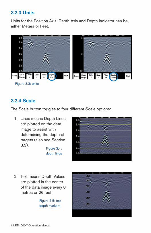
3.2.3 Units
Units for the Position Axis, Depth Axis and Depth Indicator can be either Meters or Feet.
3.2.4 Scale
The Scale button toggles to four different Scale options:
Figure �.�: units
Lines means Depth Lines are plotted on the data image to assist with determining the depth of targets (also see Section �.�).
Text means Depth Values are plotted in the center of the data image every 8 metres or �6 feet:
1.
�.
Figure �.4: depth lines
Figure �.5: text depth markers
RD1000™ Operation Manual 15
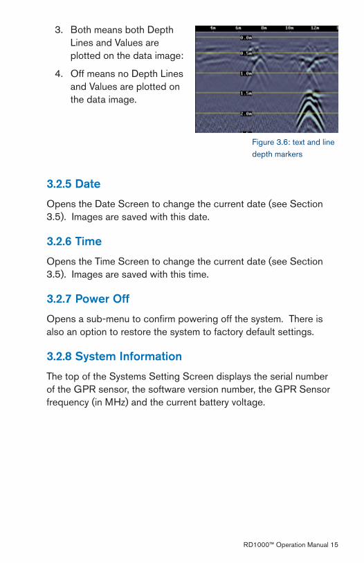
Both means both Depth Lines and Values are plotted on the data image:
Off means no Depth Lines and Values are plotted on the data image.
�.
4.
3.2.5 Date
Opens the Date Screen to change the current date (see Section �.5). Images are saved with this date.
3.2.6 Time
Opens the Time Screen to change the current date (see Section �.5). Images are saved with this time.
3.2.7 Power Off
Opens a sub-menu to confirm powering off the system. There is also an option to restore the system to factory default settings.
3.2.8 System Information
The top of the Systems Setting Screen displays the serial number of the GPR sensor, the software version number, the GPR Sensor frequency (in MHz) and the current battery voltage.
Figure �.6: text and line depth markers
16 RD1000™ Operation Manual
3.3 Scanning Screen
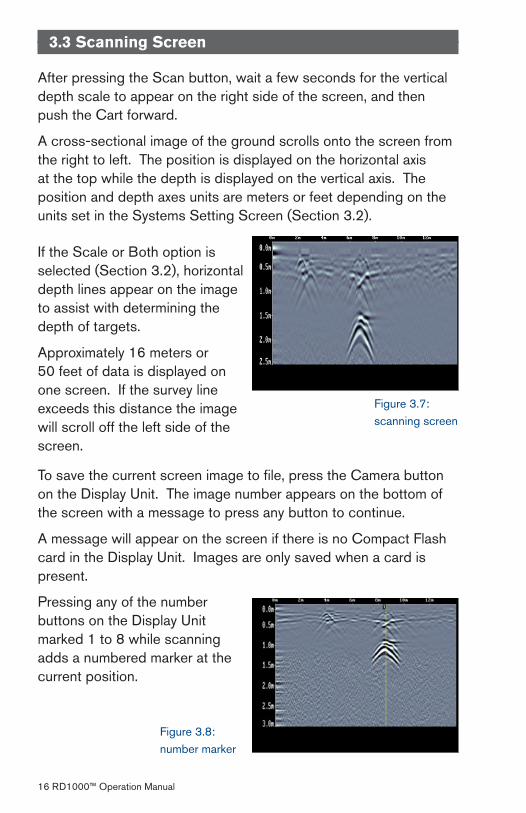
After pressing the Scan button, wait a few seconds for the vertical depth scale to appear on the right side of the screen, and then push the Cart forward.
A cross-sectional image of the ground scrolls onto the screen from the right to left. The position is displayed on the horizontal axis at the top while the depth is displayed on the vertical axis. The position and depth axes units are meters or feet depending on the units set in the Systems Setting Screen (Section �.�).
Figure �.7: scanning screen
If the Scale or Both option is selected (Section �.�), horizontal depth lines appear on the image to assist with determining the depth of targets.
Approximately 16 meters or 50 feet of data is displayed on one screen. If the survey line exceeds this distance the image will scroll off the left side of the screen.
To save the current screen image to file, press the Camera button on the Display Unit. The image number appears on the bottom of the screen with a message to press any button to continue.
A message will appear on the screen if there is no Compact Flash card in the Display Unit. Images are only saved when a card is present.
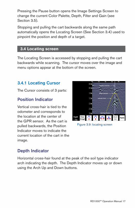
Pressing any of the number buttons on the Display Unit marked 1 to 8 while scanning adds a numbered marker at the current position.
Figure �.8: number marker
RD1000™ Operation Manual 17
Pressing the Pause button opens the Image Settings Screen to change the current Color Palette, Depth, Filter and Gain (see Section �.5).
Stopping and pulling the cart backwards along the same path automatically opens the Locating Screen (See Section �.4) used to pinpoint the position and depth of a target.
3.4 Locating screen
The Locating Screen is accessed by stopping and pulling the cart backwards while scanning. The cursor moves over the image and menu options appear at the bottom of the screen.
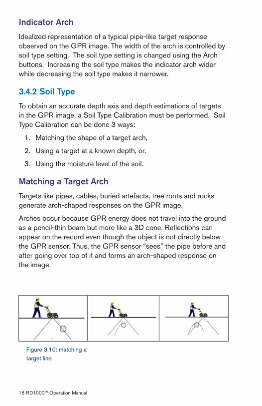
Figure �.9: locating screen
3.4.1 Locating Cursor
The Cursor consists of � parts:
Position Indicator
Vertical cross-hair is tied to the odometer and corresponds to the location at the center of the GPR sensor. As the cart is pulled backwards, the Position Indicator moves to indicate the current location of the cart in the image.
Depth Indicator
Horizontal cross-hair found at the peak of the soil type indicator arch indicating the depth. The Depth Indicator moves up or down using the Arch Up and Down buttons.
18 RD1000™ Operation Manual
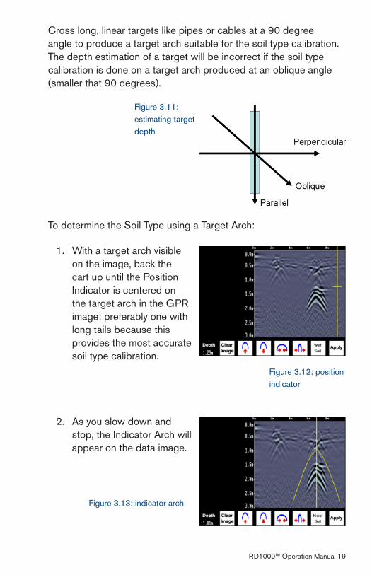
Figure �.10: matching a target line
Indicator Arch
Idealized representation of a typical pipe-like target response observed on the GPR image. The width of the arch is controlled by soil type setting. The soil type setting is changed using the Arch buttons. Increasing the soil type makes the indicator arch wider while decreasing the soil type makes it narrower.
3.4.2 Soil Type
To obtain an accurate depth axis and depth estimations of targets in the GPR image, a Soil Type Calibration must be performed. Soil Type Calibration can be done � ways:
Matching the shape of a target arch,
Using a target at a known depth, or,
Using the moisture level of the soil.
Matching a Target Arch
Targets like pipes, cables, buried artefacts, tree roots and rocks generate arch-shaped responses on the GPR image.
Arches occur because GPR energy does not travel into the ground as a pencil-thin beam but more like a �D cone. Reflections can appear on the record even though the object is not directly below the GPR sensor. Thus, the GPR sensor “sees” the pipe before and after going over top of it and forms an arch-shaped response on the image.
1.
�.
�.
RD1000™ Operation Manual 19
Figure �.11: estimating target depth
Cross long, linear targets like pipes or cables at a 90 degree angle to produce a target arch suitable for the soil type calibration. The depth estimation of a target will be incorrect if the soil type calibration is done on a target arch produced at an oblique angle (smaller that 90 degrees).
To determine the Soil Type using a Target Arch:
With a target arch visible on the image, back the cart up until the Position Indicator is centered on the target arch in the GPR image; preferably one with long tails because this provides the most accurate soil type calibration.
1.
As you slow down and stop, the Indicator Arch will appear on the data image.
�.
Figure �.1�: position indicator
Figure �.1�: indicator arch

�0 RD1000™ Operation Manual
Use the Up and Down Arrows to move the Indicator Arch shallower or deeper in the GPR image respectively, until it lies over the top of the target arch.
�.
Figure �.14: indicator arch cont.
Figure �.15: indicator arch cont.
Figure �.16: indicator arch cont.
Press the Soil Type button and toggle through the five different soil types to find the one that roughly fits the shape of the Indicator Arch to the shape of the Target Arch.
4.
Use the Wide and Narrow Arch buttons to change the shape of the Indicator Arch to match the shape of the Target Arch on the GPR image. The depth of the target is indicated on the bottom left.
5.
Press the Apply button to save the Soil Type and update the Depth Axis on the Scanning Screen. The Depth axis can now be used to estimate the depth of targets while scanning in the area.
6.
RD1000™ Operation Manual �1
Target at Known Depth
If there are no suitable arches visible in the image to perform the Target Arch Matching described above, there may be a target of known depth in the area being scanned.
To determine the Soil Type using a target at known depth:
With the target response visible on the image, use the Up and Down Arrows to move the Depth Indicator (and Indicator Arch) until it lies on top of the GPR response of the known target.
Use the Wide and Narrow Arch buttons to change the shape of the Indicator Arch until the depth of the target, displayed in red above the menu, is correct.
Once the depth is matched, save the Soil Type value by pressing the Save button.
Soil Moisture
If a good target arch or a target of known depth is not available, the user will have to estimate the Soil Type. The soil type is most strongly affected by water so the soil type options relate to the amount of water in the soil.
Change the soil type by pressing the Soil Moisture button until the option that best describes the soil in the area is displayed. The options are Very Dry, Dry, Moist, Wet and Very Wet Soil.
1.
�.
�.
�� RD1000™ Operation Manual
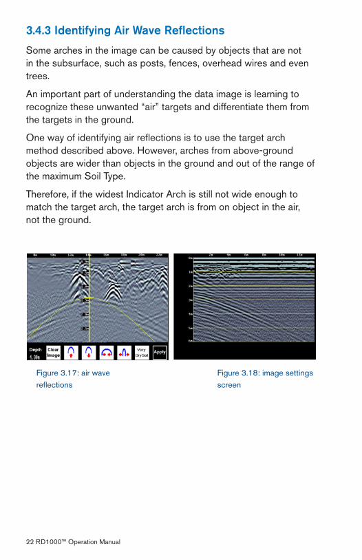
3.4.3 Identifying Air Wave Reflections
Some arches in the image can be caused by objects that are not in the subsurface, such as posts, fences, overhead wires and even trees.
An important part of understanding the data image is learning to recognize these unwanted “air” targets and differentiate them from the targets in the ground.
One way of identifying air reflections is to use the target arch method described above. However, arches from above-ground objects are wider than objects in the ground and out of the range of the maximum Soil Type.
Therefore, if the widest Indicator Arch is still not wide enough to match the target arch, the target arch is from on object in the air, not the ground.
Figure �.18: image settings screen
Figure �.17: air wave reflections
RD1000™ Operation Manual ��
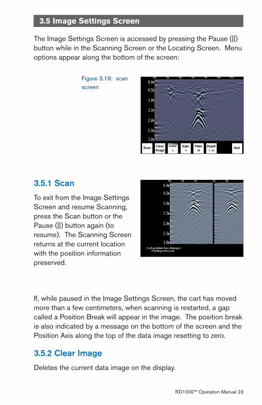
Figure �.19: scan screen
3.5 Image Settings Screen
The Image Settings Screen is accessed by pressing the Pause (||) button while in the Scanning Screen or the Locating Screen. Menu options appear along the bottom of the screen:
3.5.1 Scan
To exit from the Image Settings Screen and resume Scanning, press the Scan button or the Pause (||) button again (to resume). The Scanning Screen returns at the current location with the position information preserved.
If, while paused in the Image Settings Screen, the cart has moved more than a few centimeters, when scanning is restarted, a gap called a Position Break will appear in the image. The position break is also indicated by a message on the bottom of the screen and the Position Axis along the top of the data image resetting to zero.
3.5.2 Clear Image
Deletes the current data image on the display.
�4 RD1000™ Operation Manual
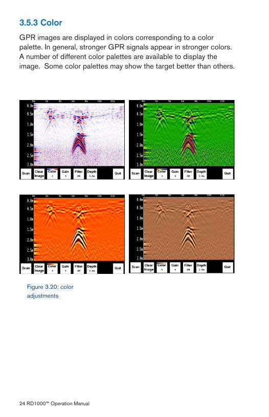
Figure �.�0: color adjustments
3.5.3 Color
GPR images are displayed in colors corresponding to a color palette. In general, stronger GPR signals appear in stronger colors. A number of different color palettes are available to display the image. Some color palettes may show the target better than others.
RD1000™ Operation Manual �5
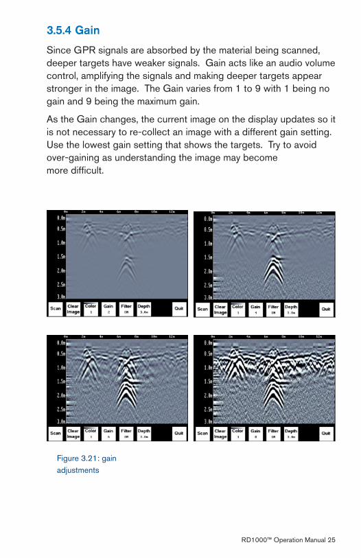
3.5.4 Gain
Since GPR signals are absorbed by the material being scanned, deeper targets have weaker signals. Gain acts like an audio volume control, amplifying the signals and making deeper targets appear stronger in the image. The Gain varies from 1 to 9 with 1 being no gain and 9 being the maximum gain.
As the Gain changes, the current image on the display updates so it is not necessary to re-collect an image with a different gain setting. Use the lowest gain setting that shows the targets. Try to avoid over-gaining as understanding the image may become more difficult.
Figure �.�1: gain adjustments
�6 RD1000™ Operation Manual
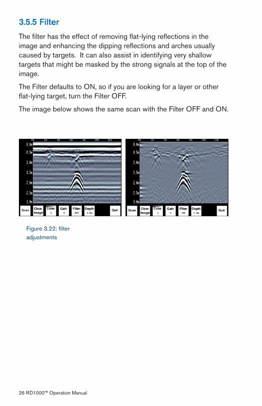
3.5.5 Filter
The filter has the effect of removing flat-lying reflections in the image and enhancing the dipping reflections and arches usually caused by targets. It can also assist in identifying very shallow targets that might be masked by the strong signals at the top of the image.
The Filter defaults to ON, so if you are looking for a layer or other flat-lying target, turn the Filter OFF.
The image below shows the same scan with the Filter OFF and ON.
Figure �.��: filter adjustments
RD1000™ Operation Manual �7
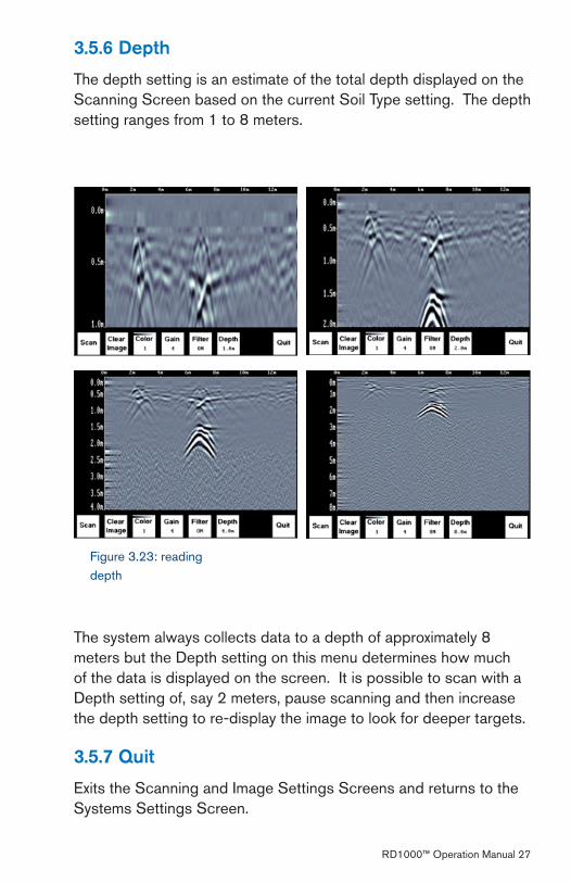
3.5.6 Depth
The depth setting is an estimate of the total depth displayed on the Scanning Screen based on the current Soil Type setting. The depth setting ranges from 1 to 8 meters.
The system always collects data to a depth of approximately 8 meters but the Depth setting on this menu determines how much of the data is displayed on the screen. It is possible to scan with a Depth setting of, say � meters, pause scanning and then increase the depth setting to re-display the image to look for deeper targets.
3.5.7 Quit
Exits the Scanning and Image Settings Screens and returns to the Systems Settings Screen.
Figure �.��: reading depth

�8 RD1000™ Operation Manual
3.6 Changing the Date and Time
To change the time:
From the System Settings Screen, select the Date option. The Time option is similar.
Use the Left and Right Arrow buttons to highlight the number to change in red.
Increase the number using the Up Arrow and decrease the number using the Down Arrow.
1.
�.
�. Figure �.�4: time and date adjustment screen
Pressing OK saves the new date or time and exits the screen.
Pressing Cancel exits the screen without saving the date or time.
4.
5.
RD1000™ Operation Manual �9
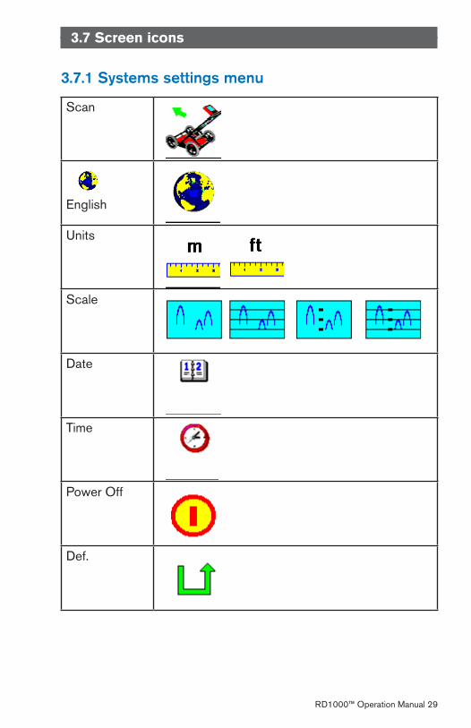
3.7 Screen icons
3.7.1 Systems settings menu
Scan
English
Units
Scale
Date
Time
Power Off
Def.
�0 RD1000™ Operation Manual
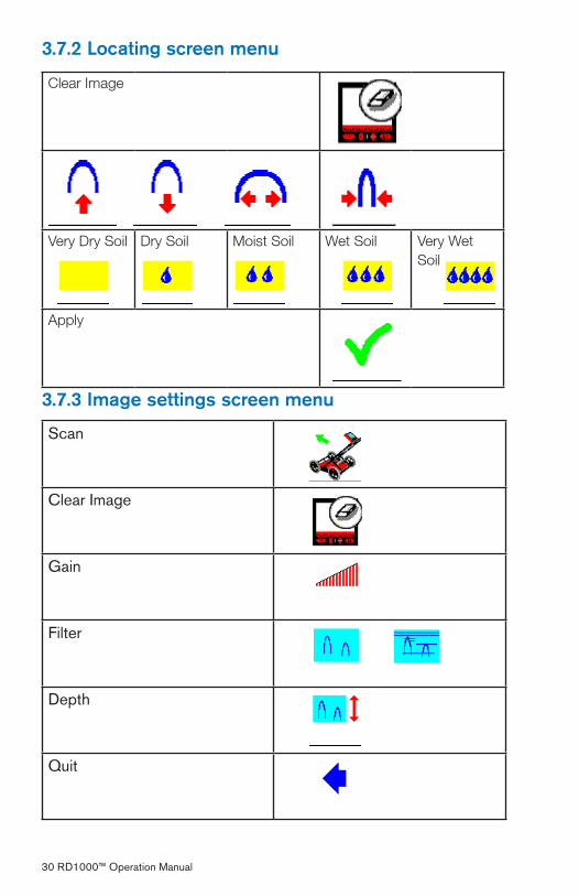
3.7.2 Locating screen menu
Clear Image
Very Dry Soil Dry Soil Moist Soil Wet Soil Very Wet Soil
Apply
3.7.3 Image settings screen menu
Scan
Clear Image
Gain
Filter
Depth
Quit
RD1000™ Operation Manual �1
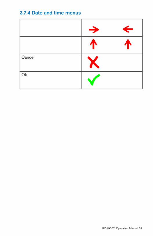
3.7.4 Date and time menus
Cancel
Ok
�� RD1000™ Operation Manual
Section 4 Surveying Techniques
4.1 Cross and mark
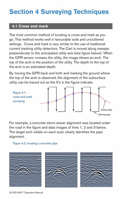
The most common method of locating is cross and mark as you go. This method works well in favourable soils and uncluttered settings. Cross and mark is very similar to the use of traditional current tracking utility detectors. The Cart is moved along sweeps perpendicular to the anticipated utility axis (see figure below). When the GPR sensor crosses the utility, the image shows an arch. The top of the arch is the position of the utility. The depth to the top of the arch is an estimated depth.
By moving the GPR back and forth and marking the ground where the top of the arch is observed, the alignment of the subsurface utility can be traced out as the X’s in the figure indicate.
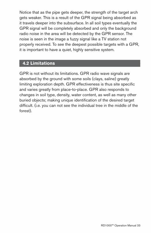
For example, a concrete storm sewer alignment was located under the road in the figure and data images of lines 1, � and � below. The target arch visible on each scan clearly identifies the pipe alignment.
Figure 4.1: cross and mark surveying
Figure 4.�: locating a concrete pipe
RD1000™ Operation Manual ��
Notice that as the pipe gets deeper, the strength of the target arch gets weaker. This is a result of the GPR signal being absorbed as it travels deeper into the subsurface. In all soil types eventually the GPR signal will be completely absorbed and only the background radio noise in the area will be detected by the GPR sensor. The noise is seen in the image a fuzzy signal like a TV station not properly received. To see the deepest possible targets with a GPR, it is important to have a quiet, highly sensitive system.
4.2 Limitations
GPR is not without its limitations. GPR radio wave signals are absorbed by the ground with some soils (clays, saline) greatly limiting exploration depth. GPR effectiveness is thus site specific and varies greatly from place-to-place. GPR also responds to changes in soil type, density, water content, as well as many other buried objects; making unique identification of the desired target difficult. (i.e. you can not see the individual tree in the middle of the forest).
�4 RD1000™ Operation Manual
Section 5 TroubleshootingThe system is designed to minimize user problems; however, all electronic devices are subject to possible failure. The following are troubleshooting hints in the likelihood of occurrence if your system fails to operate.
5.1 Power
The most common problem that can occur while trying to run the system is insufficient power. The battery may be dead, have a low voltage or the fuse may be blown.
If there is enough power to run the Display Unit, the upper red light on the front of the Display Unit will illuminate when the battery is plugged in.
If the battery voltage is less than about 10.� volts, the Display Unit may not turn on and the upper red light will flash or not illuminate at all.
Check that battery voltage with a voltmeter. Try to do this while the system is still attached to the Cart to get a true measure of the voltage while under load (it will be necessary to open the Cart battery case and connect the voltmeter to the positive and negative battery terminals). If the battery has a low voltage or seems dead, try the system with another battery (if available), or give the battery a good 1�-14 hour charge and try running the system again.
If the battery does not charge up to 1� Volts or more, it should be replaced.
Batteries are fused to protect the system. Open the battery case and check that the 10 Amp fuse is OK. If necessary, replace it with one of the spare fuses available inside the battery case.
If the battery seems OK but the system still does not power up, check the battery cable connections and inspect the battery cable for damage.

RD1000™ Operation Manual �5
5.2 System Communications
If the battery is OK and the Display Unit turns on but the GPR sensor does not scan, there may be a communication failure between the Display Unit and the GPR sensor. If an error occurs, an error message will appear. Power Off the system and disconnect the battery.
Make sure the display cable is not damaged; all pins are straight and blow out the connector sockets as small debris may block individual pin connections and disrupt communications. Ensure that the cable connections are tightly secured. Sometimes vibrations cause the cable connections to loosen just a bit and break contact and this can cause errors. Disconnecting the cable and reconnecting it may provide a better contact and solve the problem. Plug in the battery, turn on the system and try scanning again.
If the battery, Battery Cable and Display Cable are OK, the problem is either a failure of the Display Unit or the GPR sensor. These units have no user-serviceable parts so it will have to the vendor for inspection and possible repair.
5.3 System Overheating
The GPR system is designed to operate to a maximum internal temperature of 70 C or 158 F. In situations of high ambient temperatures or long exposure to direct sun, this maximum internal temperature may be exceeded and cause the system to fail.
If you suspect that the GPR sensor is overheating, shut it off and give it a chance to cool down in a shady location before trying to run it again. Placing a wet cloth on top of the GPR may help in cooling it down.
If the situation is such that the high temperatures or direct sun cannot be avoided, it may be a good idea to put some sort of shade over the GPR sensor.
�6 RD1000™ Operation Manual
5.4 Display Unit Problem
While the Display Unit is weatherproof and fairly rugged, it should be handled in much the same way a notebook computer is. If the Display Unit does not power up, there may be a problem with the CPU or the storage media. Always make sure that the access port on the top of the display unit is closed and sealed.
5.5 Test Line
One of the best ways of detecting problems with the system is, shortly after receiving the system and getting comfortable with its operation, collect a line of data at a convenient, easily accessible location. The line does not have to be too long but one screen (16 meters or 50 feet) is a good guide. This data line should be saved electronically and perhaps plotted out on paper and dated. The test line could be collected say, every 6 months and, by reviewing the previous data, system problems can be detected early. As well, if there is a suspected problem with the system, this test line could be collected and compared with earlier tests.
5.6 Contacting the Vendor for Service
When returning the Vendor, have the following information available:
GPR sensor Serial Number displayed at the top of the System Settings Screen.
A brief description of when the error is happening and the operating conditions (temperature, humidity, sunshine, system settings, etc.).
1.
�.
RD1000™ Operation Manual �7
Section 6 Care and Maintenance
6.1 Battery Care
The RD1000 uses a 9-Amp-hour, 1�-Volt sealed lead acid battery. It is fused with a 10 Amp fuse to protect it from short circuit damage.
The battery unit should run the Cart for 6-8 hours before recharging is necessary. If long days of data surveying are typical, a second battery unit may be a useful item.
The battery is strapped onto the cart base and is normally recharged without removing it from the cart. However, the battery can be easily removed for maintenance or for recharging, if required.
If batteries are maintained in a charged condition they will give long life and reliable service. Improper use and lack of maintenance will greatly reduce their life.
Sealed lead acid batteries should NEVER be left in a discharged condition for any period of time. Charge the batteries as soon as possible after use.
Charge the battery at room temperature whenever possible.
The RD1000 has a voltage monitoring circuit that will turn off the unit when the input voltage drops below 10.� volts.
If a battery has been deeply discharged or left in a discharged condition for some period of time it may not accept charge immediately when it is connected to the charger (The fast charge light will not illuminate). If the fast charge light does not come on within 6 hours the battery should be considered damaged and should be discarded.
Do not assume that a battery that is still charging after 8 hours is nearing the end of its charge cycle. Typical charging time for an empty battery is 1�-14 hours from start of fast charge.
�8 RD1000™ Operation Manual
Ensure that the batteries are fully charged before storing. If practical, store the batteries in a cool place, 10oc (a refrigerator is ideal), but make sure the temperature is not likely to drop below -�0oC or the electrolyte may freeze and possibly split the case.
6.2 Cable Care
The cable connectors as well as the connectors on the GPR Sensor and Display Unit need to stay clean and free of dust and moisture. Use a brush or air spray to clean dust, lint and other foreign particles from these connectors.
When the system is not being used, make sure the connections are done up to prevent dust and moisture from collecting inside. If the connectors are exposed, cover them with some sort of dust cap.
Cables are designed to be as tough as practical.
Careless use of cables making them carry loads that they are not designed for can cause internal damage.
Connectors are weak points in any system. With the use of this product in rough, dusty and outdoor environments, users can minimize potential down time if they care for cables and treat connectors with respect.
Cables and connectors are not designed to suspend or tow or otherwise carry the weight of systems. They are part of the electronic circuit and should be treated accordingly. When not in use they should be placed in their storage box.
1.
�.
�.
4.
5.
6.
RD1000™ Operation Manual �9
6.3 Skid Pad
The bottom of the GPR Sensor is covered with one large wear-resistant skid pad. The skid pad is designed to take the majority of the abrasive wear. If the pad wears down enough, the less-resistant plastic housing may start to wear. If this occurs, it is best to replace the skid pad. It is easily removed with a screwdriver and a new one can be purchased from the vendor.
6.4 Odometer
The odometer is factory calibrated and does not require maintenance.
40 RD1000™ Operation Manual
Appendix A
GPR Emissions, Interference and Regulations
All governments have regulations on the level of electromagnetic emissions that an electronic apparatus can emit. The objective is to assure that one apparatus or device does not interfere with any other apparatus or device in such a way as to make the other apparatus non-functional.
The manufacturer test their GPR products using independent professional testing houses and comply with latest regulations of the USA, Canada, European Community, and other major jurisdictions on the matter of emissions.
Electronic devices have not always been designed for proper immunity. If a GPR instrument is placed in close proximity to an electronic device, interference may occur. While there have been no substantiated reports of interference to date, if any unusual behavior is observed on nearby devices, test if the disturbance starts and stops when the GPR instrument is turned on and off. If interference is confirmed, stop using the GPR.
Where specific jurisdictions have specific GPR guidelines, these are described below.
FCC Regulations
This device complies with Part 15 of the USA Federal Communications Commission (FCC) Rules. Operation in the USA is subject to the following two conditions:
this device may not cause harmful interference and
this device must accept any interference received, including interference that may cause undesired operation.
Part 15 – User Information
This equipment has been tested and found to comply with the limits for a Class A digital device, where applicable, and for an ultrawide
1.
�.
RD1000™ Operation Manual 41
bandwidth (UWB) device where applicable, pursuant to Part 15 of the FCC Rules. These limits are designed to provide reasonable protection against harmful interference when the equipment is operated in a commercial environment. This equipment generates, uses and can radiate radio frequency energy and, if not installed and used in accordance with the instruction manual, may cause harmful interference to radio communications. Operation of this equipment in a residential area is likely to cause harmful interference in which case the user will be required to correct the interference at his own expense.
WARNING
Changes or Modifications not expressly approved by the manufacturer could void the user’s authority to operate the equipment.
Certification of this equipment has been carried out using approved cables and peripheral devices. The use of non-approved or modified cables and peripheral devices constitutes a Change or Modification outlined in the warning above.
Operating Restrictions
Operation of this device is limited to purposes associated with law enforcement, fire fighting, emergency rescue, scientific research, commercial mining, or construction. Parties operating this equipment must be eligible for licensing under the provisions of Part 90 of this chapter.
FCC Interpretation of Operation Restrictions issued July 12, 2002
(FCC Order DA0�-1658, paragraph 9)
The regulations contain restrictions on the parties that are eligible to operate imaging systems (See 47 C.F.R. §§15.509(b), 15.511(b), and 15.51�(b)). Under the new regulations, GPRs and wall imaging systems may be used only by law enforcement, fire and emergency rescue organizations, by scientific research institutes, by commercial mining companies, and by construction companies. Since the adoption of the Order, we have received several inquiries from the operators of GPRs and wall imaging systems noting
4� RD1000™ Operation Manual
that these devices often are not operated by the users listed in the regulations but are operated under contract by personnel specifically trained in the operation of these devices. We do not believe that the recent adoption of the UWB rules should disrupt the critical safety services that can be performed effectively only through the use of GPRs and wall imaging systems. We viewed these operating restrictions in the broadest of terms. For example, we believe that the limitation on the use of GPRs and wall imaging systems by construction companies encompasses the inspection of buildings, roadways, bridges and runways even if the inspection finds no damage to the structure and construction does not actually result from the inspection; the intended purpose of the operation of the UWB device is to determine if construction is required. We also believe that the GPRs and wall imaging systems may be operated for one of the purposes described in the regulations but need not be operated directly by one of the described parties. For example, a GPR may be operated by a private company investigating forensic evidence for a local police department.
FCC Permitted Mode of Usage
The GPR antenna must be kept on the surface to be in compliance with FCC regulations. Use of the antenna is not permitted if it is lifted off the surface. Use as a through-the-wall imaging device is prohibited.
GPR Use Coordination
FCC regulation 15.5�5(c) (updated in February �007) requires users of GPR equipment to coordinate the use of their GPR equipment as described below:
(a) UWB imaging systems require coordination through the FCC before the equipment may be used. The operator shall comply with any constraints on equipment usage resulting from this coordination.
(b) The users of UWB imaging devices shall supply operational areas to the FCC Office of Engineering and Technology, which shall coordinate this information with the Federal Government through the National Telecommunications and Information Administration. The information provided by the UWB operator shall include the
RD1000™ Operation Manual 4�
name, address and other pertinent contact information of the user, the desired geographical area(s) of operation, and the FCC ID number and other nomenclature of the UWB device. If the imaging device is intended to be used for mobile applications, the geographical area(s) of operation may be the state(s) or county(ies) in which the equipment will be operated. The operator of an imaging system used for fixed operation shall supply a specific geographical location or the address at which the equipment will be operated. This material shall be submitted to:
Frequency Coordination Branch, OET
Federal Communications Commission
445 1�th Street, SW,
Washington, D.C. �0554
Attn: UWB Coordination
The form given on the following page is a suggested format for performing the coordination.
44 RD1000™ Operation Manual
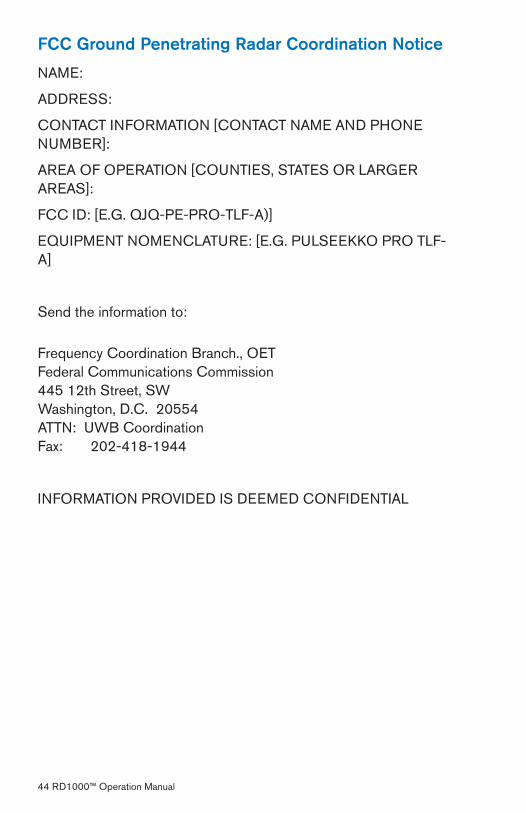
FCC Ground Penetrating Radar Coordination Notice
NAME:
ADDRESS:
CONTACT INFORMATION [CONTACT NAME AND PHONE NUMBER]:
AREA OF OPERATION [COUNTIES, STATES OR LARGER AREAS]:
FCC ID: [E.G. QJQ-PE-PRO-TLF-A)]
EQUIPMENT NOMENCLATURE: [E.G. PULSEEKKO PRO TLF-A]
Send the information to:
Frequency Coordination Branch., OETFederal Communications Commission445 1�th Street, SWWashington, D.C. �0554ATTN: UWB CoordinationFax: �0�-418-1944
INFORMATION PROVIDED IS DEEMED CONFIDENTIAL

RD1000™ Operation Manual 45
ETSI Regulations for the EC
In the European Community (EC), GPR instruments must conform to ETSI (European Technical Standards Institute) standard EN�0�066. Details on individual country requirements for licensing are coordinated with this standard. For more information, contact the GPR system vendor.
This GPR product offered for sale in European Community countries or countries adhering to ETSI standards is tested to comply with EN�0�066.

Radiodetection products are under continuous development and are subject to change, we reserve the right to alter or amend any published specification without notice.
RD1000 is a Trademark of Radiodetection Ltd.
Copyright 2008 Radiodetection Limited. All rights reserved. Radiodetection Ltd. is a subsidiary of SPX Corporation.