mcdonald, katrina and pearcy, mark j and adam, clayton j ...eprints.qut.edu.au/11300/1/11300.pdf ·...
TRANSCRIPT
McDonald, Katrina and Pearcy, Mark J and Adam, Clayton J (2007) The effect of trabecular micro-architecture on vertebra biomechanics: a finite element investigation. In Brebbia, CA, Eds. Proceedings 7th International conference on Modelling in Medicine and Biology (Biomed 2007) 12, pages pp. 103-112, Wessex Institute of Technology, New Forest, United Kingdom. This is the author-manuscript version of this work - accessed from http://eprints.qut.edu.au Copyright 2007 WIT Press
The effect of trabecular micro-architecture on vertebra biomechanics: A Finite Element investigation
K. McDonald, M. J. Pearcy, C. J. Adam Institute of Health and Biomedical Innovation, Queensland University of Technology, Brisbane, Australia
Abstract
700,000 vertebral fractures occur each year in the United States alone, 85% of which are associated with osteoporosis. This study presents the development of a microstructural model of an entire lumbar vertebral body to investigate the effects of osteoporotic changes in bone micro-architecture on vertebral biomechanics, specifically, the change in stiffness, stresses and load sharing capacity of the core and cortex. A finite element model of a trabecular microstructure was created using a lattice of 3D beam elements with age representative thickness and separation. The vertebral shell was created around the trabecular microarchitecture using 3D shell elements. Three trabecular microstructures were investigated: (i) age less than 50, (ii) age 50-75 and (iii) age over 75 years. A Young’s modulus of 13GPa and Poisson’s ratio of 0.3 were applied for parent bone material. Two loading cases were investigated; (i) a uniform pressure of 1MPa applied to the upper endplate, and (ii) an applied displacement of -1mm for the entire upper endplate in the vertical direction. Model results showed that, microstructural variations seen with aging decreased predicted vertebral stiffness from 23kN/mm (age <50) to 0.7kN/mm (age >75), increased maximum principal endplate stress from 5.4MPa (age <50) to 73MPa (age >75, for 1MPa applied pressure), and reduced the proportion of total load carried by the trabecular core from 52% (age <50) to 6% (age >75). The model exhibits realistic behaviour compared with experimental studies, and will be used in the future to explore the mechanics of vertebral compression fractures and treatments such as vertebroplasty Keywords: Vertebra, trabecular microarchitecture, FE modelling, osteoporosis
1 Introduction
The National Institute of Health (NIH) estimate that 30-50% of women and 20-30% of men will develop a vertebral fracture in their lifetime. 700,000 vertebral fractures occur each year in the United States alone, 85% of which are associated with osteoporosis. Osteoporosis is a disease which compromises bone mineral density and trabecular micro-architecture, resulting in increased fragility and susceptibility to fracture. The microarchitectural changes which occur in osteoporosis have been well documented. Osteoporosis results in thinning of the trabeculae, increased spacing between trabeculae, and thinning of the cortical shell of the vertebrae. Although the microarchitectural changes have been thoroughly explored, the effects of these changes on whole vertebra biomechanics are still not well understood. Finite element (FE) analysis is a tool which has been used to explore the effect of changes in trabecular microarchitecture on vertebra mechanics. Researchers have generally approached this problem using either micro-structural (meshing the trabecular architecture for a small region of bone), or macro-structural (meshing the entire vertebra using solid elements) models. Three dimensional macro-structural models are typically derived from CT scans which provide the external geometry of the vertebral body. In this case, the trabecular microstructure is not modelled, instead CT greyscale values are used to assign an apparent elastic modulus to each solid element throughout the model. While this provides a representation of the vertebra as a whole structure, it does not permit investigation of the effect of trabecular microstructure on overall vertebra mechanics. FE studies investigating trabecular bone microstructure have used either voxel based solid models derived from micro-CT scans of small regions of bone, or beam element representations of the trabecular bone network. While voxel based models realistically represent the actual trabecular structure in a specific bone sample, they are computationally intensive and do not allow systematic variation in trabecular microstructure. Conversely, three dimensional micro-beam models use a mathematical representation of the microstructure which allows systematic control of trabecular microarchitecture at much lower computational expense. Micro-beam models are created using an array of beams in which control of beam thickness, separation and orientation in three dimensions is permitted. The computational ease of these elements allows large structures to be created. To the authors’ knowledge however, previous micro-beam models have only been used to predict apparent properties of small regions of trabecular bone, rather than incorporating micro-beams into the macro models to investigate the effects of microarchitectural changes on the overall response of a vertebra. Accordingly, this study employs a combination of beam elements to represent the trabecular micro-architecture, and shell elements to represent the vertebral cortex, to create a realistic, micro-structural vertebra model. The paper presents the development of this microstructural model of an entire lumbar vertebral body and preliminary simulations to investigate the effects of changes in trabecular
bone micro-architecture on the vertebral stiffness, stresses around the cortex, and load carriage between the vertebral cortex and trabecular core.
2 Methods
A finite element model of an L3 human lumbar vertebral body was created using equations given by Mizrahi [1] for the vertebral body geometry. In Mizrahi’s study, a parametric approach was used to create an idealised cortex geometry that was a general population representation, and that did not have the computational difficulty associated with models derived from images. Four sets of equations were used to describe the nonuniform taper of the cortical shell, the endplate curvature and the “tear-drop” cross section geometry. This created a parametric vertebral body which did not include the posterior elements, as they have been shown to play a minor role in axial compression loading [2]. To ensure the cortex was an accurate representation of an L3 vertebra body, the geometry was compared with published values of human vertebral geometry in the literature [3-5]. The greatest geometric dimensional difference between the parametric model and a human vertebra was 15%, with an average variation of 7%. This was considered a reasonable approximation. The model was shelled to a thickness of 0.68mm to represent the thickness of the cortical wall [6]. The vertebral cortex was meshed using 2.5mm triangular shell elements. The internal trabecular microstructure was created by generating a three dimensional matrix of nodes. The spacing between nodes in each plane was determined using values published by Mosekilde [7] and the values used are shown in Table 1. Different spacing values were used for the transverse and longitudinal planes. Three models were produced with age representative trabecular spacings and diameters to characterize trabecular microarchitecture at age <50, age 50 to 75, and age >75 years. An additional perturbation was added to the coordinates of each node in the trabecular microstructure, to provide a degree of random irregularity in the structure, as occurs in real bone. The perturbation value defines how far each node is able to move along each plane from its original coordinate. Hence a low perturbation results in a relatively square matrix whilst a high perturbation gives an irregular matrix. Jenson [8] found perturbation values between 0.4 and 0.8 to be most appropriate for human trabecular bone, and therefore a perturbation value of 0.6 was employed for the model. This allowed each node point to move by ±30% of the original spacing value in each plane. Three dimensional beam elements were added between the node points to create a three dimensional lattice. The beam thickness values were set to correspond with the models of various ages. These values were again acquired from published values by Mosekilde [7] and are shown in Table 1.
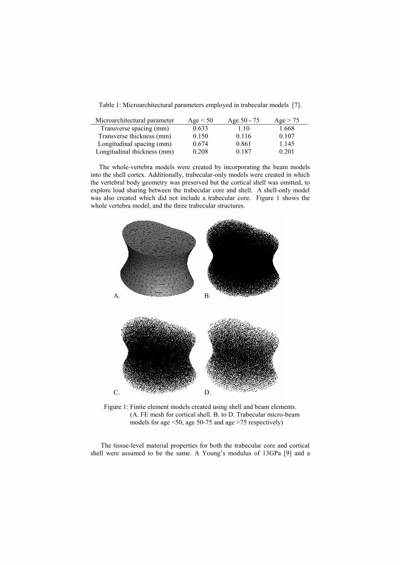
Table 1: Microarchitectural parameters employed in trabecular models [7].
Microarchitectural parameter Age < 50 Age 50 - 75 Age > 75 Transverse spacing (mm) 0.633 1.10 1.668
Transverse thickness (mm) 0.150 0.116 0.107 Longitudinal spacing (mm) 0.674 0.861 1.145
Longitudinal thickness (mm) 0.208 0.187 0.201 The whole-vertebra models were created by incorporating the beam models into the shell cortex. Additionally, trabecular-only models were created in which the vertebral body geometry was preserved but the cortical shell was omitted, to explore load sharing between the trabecular core and shell. A shell-only model was also created which did not include a trabecular core. Figure 1 shows the whole vertebra model, and the three trabecular structures.
Figure 1: Finite element models created using shell and beam elements.
(A. FE mesh for cortical shell. B. to D. Trabecular micro-beam models for age <50, age 50-75 and age >75 respectively)
The tissue-level material properties for both the trabecular core and cortical shell were assumed to be the same. A Young’s modulus of 13GPa [9] and a
A. B.
C. D.
Poisson’s ratio of 0.3 was applied for parent bone material. The models were solved using ABAQUS/Standard (version 6.6, Abaqus Inc, RI, USA). The ABAQUS nonlinear geometry capability was used to include the effects of large deformations and displacements in solving the model. Two loading cases were applied to each model. The first was a uniform distribution of pressure (1MPa) over the top end plate of the vertebrae. Given the area of the endplate was 1268 mm2 this pressure was equivalent to a force of 1268N on the vertebra body. This is approximately twice the normal load the vertebra experiences in relaxed standing for a 60kg individual, however the 1MPa pressure allows convenient interpretation of results. The second loading case was an applied displacement to the entire top endplate in the negative z direction by 1mm. This loading case simulates in-vitro compression testing, in which both endplates are rigidly potted in bone cement and an applied displacement is used to load the vertebra to assess compressive stiffness and/or strength. In both load cases, the bottom endplate was constrained in all three degrees of freedom.
3 Results
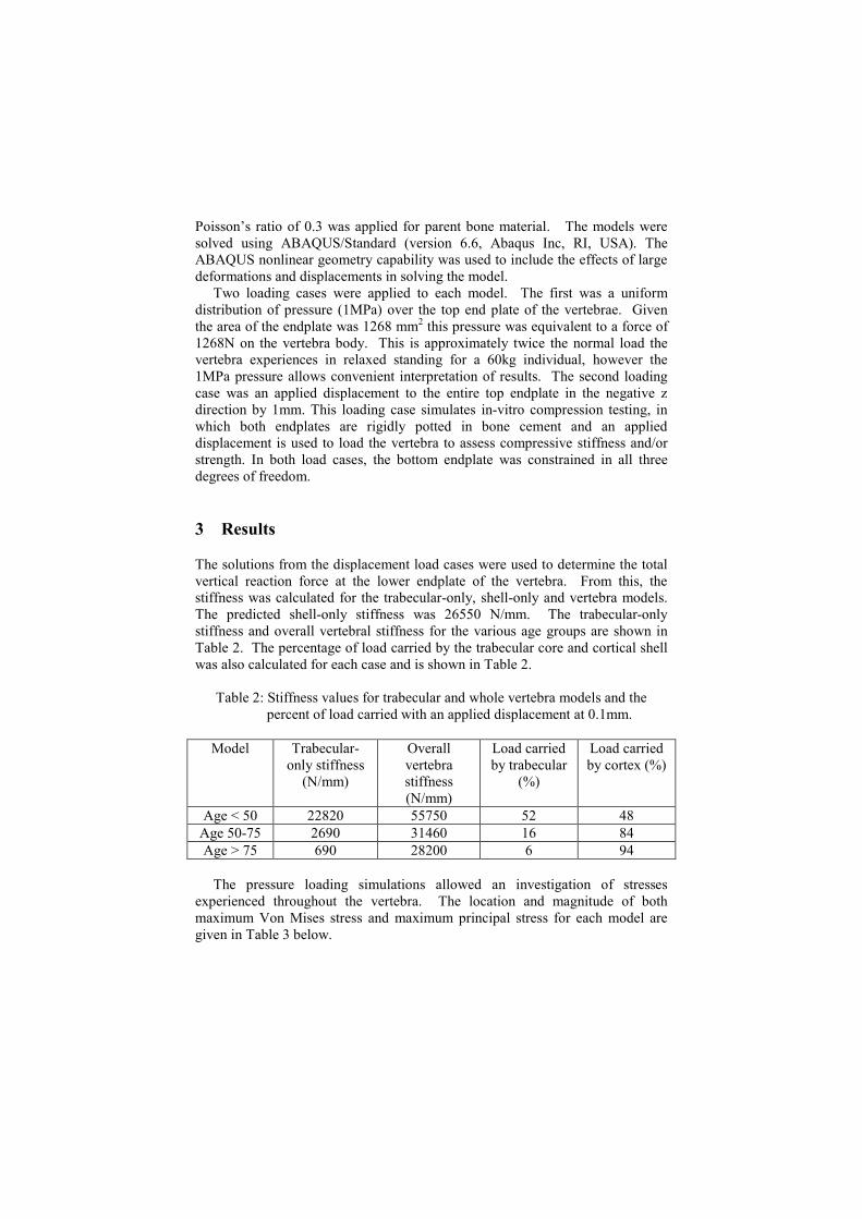
The solutions from the displacement load cases were used to determine the total vertical reaction force at the lower endplate of the vertebra. From this, the stiffness was calculated for the trabecular-only, shell-only and vertebra models. The predicted shell-only stiffness was 26550 N/mm. The trabecular-only stiffness and overall vertebral stiffness for the various age groups are shown in Table 2. The percentage of load carried by the trabecular core and cortical shell was also calculated for each case and is shown in Table 2.
Table 2: Stiffness values for trabecular and whole vertebra models and the percent of load carried with an applied displacement at 0.1mm.
Model Trabecular-
only stiffness (N/mm)
Overall vertebra stiffness (N/mm)
Load carried by trabecular
(%)
Load carried by cortex (%)
Age < 50 22820 55750 52 48 Age 50-75 2690 31460 16 84 Age > 75 690 28200 6 94
The pressure loading simulations allowed an investigation of stresses experienced throughout the vertebra. The location and magnitude of both maximum Von Mises stress and maximum principal stress for each model are given in Table 3 below.
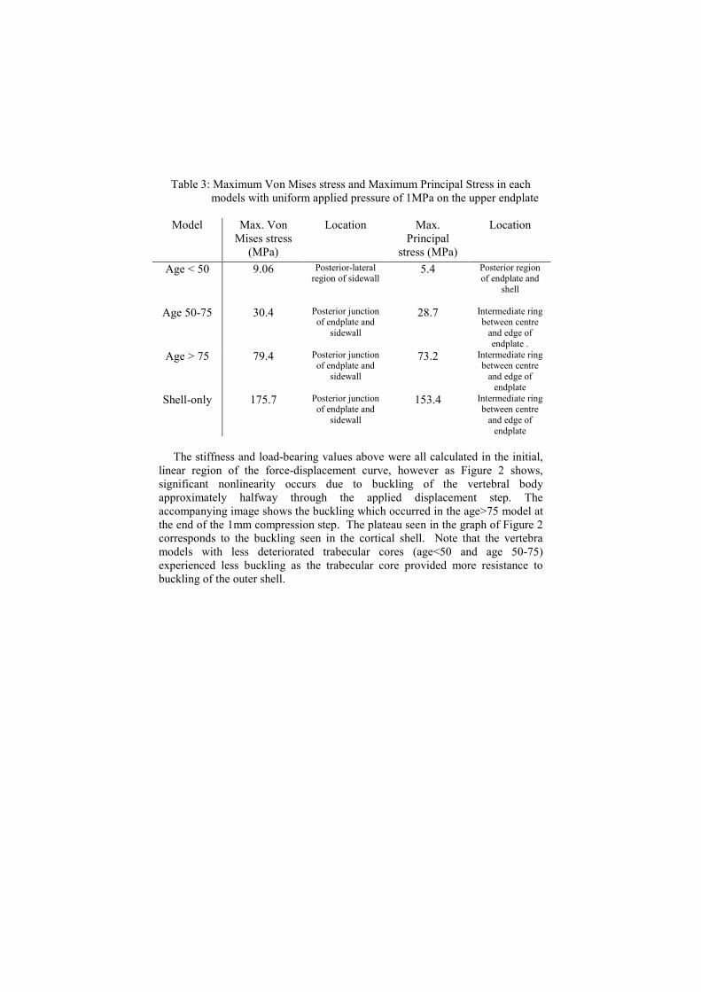
Table 3: Maximum Von Mises stress and Maximum Principal Stress in each models with uniform applied pressure of 1MPa on the upper endplate
Model Max. Von
Mises stress (MPa)
Location Max. Principal
stress (MPa)
Location
Age < 50 9.06 Posterior-lateral region of sidewall
5.4 Posterior region of endplate and
shell
Age 50-75 30.4 Posterior junction of endplate and
sidewall
28.7 Intermediate ring between centre
and edge of endplate .
Age > 75 79.4 Posterior junction of endplate and
sidewall
73.2 Intermediate ring between centre
and edge of endplate
Shell-only 175.7 Posterior junction of endplate and
sidewall
153.4 Intermediate ring between centre
and edge of endplate
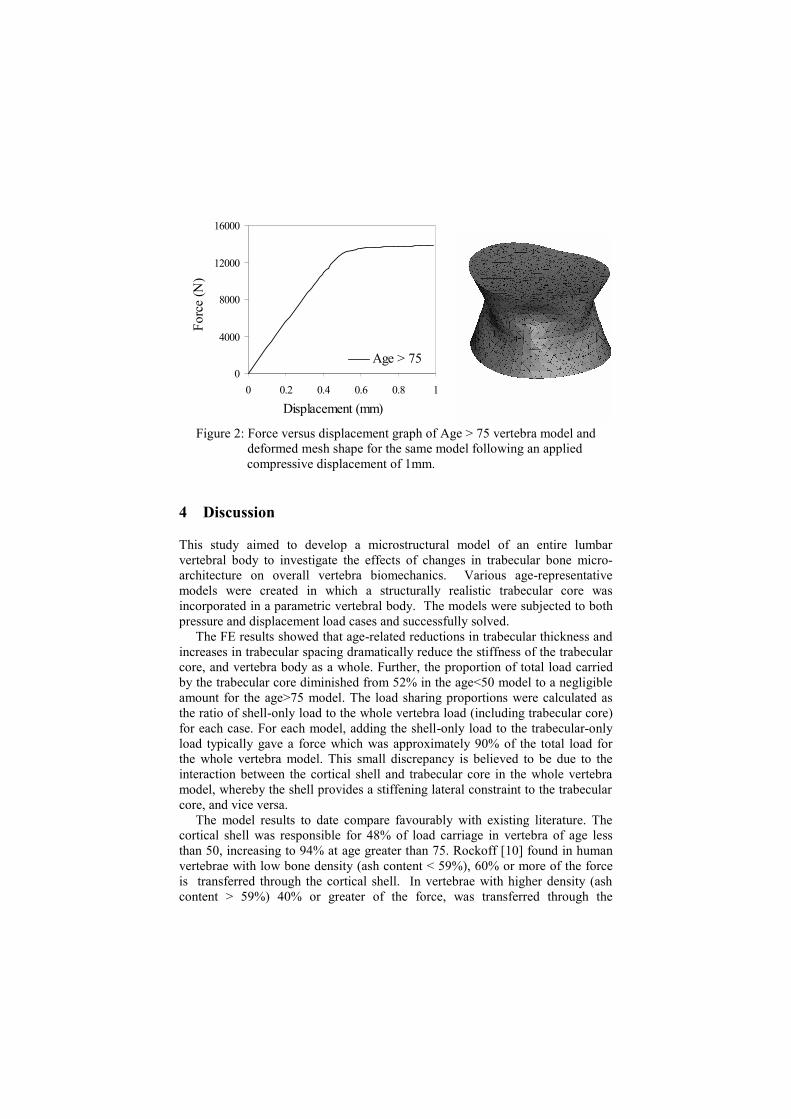
The stiffness and load-bearing values above were all calculated in the initial, linear region of the force-displacement curve, however as Figure 2 shows, significant nonlinearity occurs due to buckling of the vertebral body approximately halfway through the applied displacement step. The accompanying image shows the buckling which occurred in the age>75 model at the end of the 1mm compression step. The plateau seen in the graph of Figure 2 corresponds to the buckling seen in the cortical shell. Note that the vertebra models with less deteriorated trabecular cores (age<50 and age 50-75) experienced less buckling as the trabecular core provided more resistance to buckling of the outer shell.
0
4000
8000
12000
16000
0 0.2 0.4 0.6 0.8 1
Displacement (mm)
Forc
e (N
)
Age > 75
Figure 2: Force versus displacement graph of Age > 75 vertebra model and
deformed mesh shape for the same model following an applied compressive displacement of 1mm.
4 Discussion
This study aimed to develop a microstructural model of an entire lumbar vertebral body to investigate the effects of changes in trabecular bone micro-architecture on overall vertebra biomechanics. Various age-representative models were created in which a structurally realistic trabecular core was incorporated in a parametric vertebral body. The models were subjected to both pressure and displacement load cases and successfully solved. The FE results showed that age-related reductions in trabecular thickness and increases in trabecular spacing dramatically reduce the stiffness of the trabecular core, and vertebra body as a whole. Further, the proportion of total load carried by the trabecular core diminished from 52% in the age<50 model to a negligible amount for the age>75 model. The load sharing proportions were calculated as the ratio of shell-only load to the whole vertebra load (including trabecular core) for each case. For each model, adding the shell-only load to the trabecular-only load typically gave a force which was approximately 90% of the total load for the whole vertebra model. This small discrepancy is believed to be due to the interaction between the cortical shell and trabecular core in the whole vertebra model, whereby the shell provides a stiffening lateral constraint to the trabecular core, and vice versa. The model results to date compare favourably with existing literature. The cortical shell was responsible for 48% of load carriage in vertebra of age less than 50, increasing to 94% at age greater than 75. Rockoff [10] found in human vertebrae with low bone density (ash content < 59%), 60% or more of the force is transferred through the cortical shell. In vertebrae with higher density (ash content > 59%) 40% or greater of the force, was transferred through the
trabecular core. Yoganandan [11] stated similar values. That study showed the mean load bearing proportion for the cortical shell in human vertebrae was 35%. The study found the contribution of load bearing in an osteoporotic vertebra was 74%. These load sharing proportions are similar to those of the current model, as is the significant increase in load bearing responsibility of the cortical shell with a decrease in trabecular density. The force-displacement graph of Figure 2 showed strongly non linear behaviour due to buckling of the cortical shell in the vertebra models with less internal trabecular support (age>75 and the shell-only model). The buckling occurred at a compressive force of approximately 14kN, which is within the range of vertebral body strength data reported in the literature; however, it is likely that high endplate stresses would have caused localised fracturing of the cortex before this dramatic buckling occurred. The nonlinear behaviour seen in these models demonstrates the importance of performing finite strain analyses in FE simulations of vertebrae subjected to compressive loads. The models also predicted a large increase in maximum stress with the degraded trabecular structures. The maximum von Mises stress was almost 9 times greater, and the maximum principal stress almost 14 times greater, in the models of age > 75, compared to those of age < 50. The locations of the maximum von Mises and maximum principal stress also changed between the various aged models. The maximum von Mises stress was observed in the healthiest model to be along the sidewalls of the shell, whereas the older models presented the highest stress at the junction between the endplate and sidewalls. The location of peak maximum principal stress also changed with aging. The healthiest model predicted the highest principal stress in the posterior region of the shell and endplate. With aging, the highest principal stresses occurred in an annular ring in the endplate, located intermediately with respect to the centre and edge of the endplate. These maximum principal stress locations always occurred in the upper endplate for the uniform pressure loading case (Table 3), a finding in general agreement with the observation that endplate fracture tends to occur prior to cortical sidewall collapse in biomechanical testing of vertebral bodies. The 1MPa uniform pressure loading case which was applied to the vertebra is approximately double the axial load on the lumbar spine in relaxed standing, but loads of this magnitude are frequently experienced in daily activities. For example, a force of 1200N has been reported to occur in activities such as laughing and bending forwards [12]. In this study however, the 1MPa pressure was primarily used for ease of interpretation of resulting stresses throughout the model. The results presented in this paper are preliminary findings obtained during the early developmental stages of this model, and the limitations should be recognised. The cortical shell is an idealised geometry based on a mathematical description in the literature and not based on any real vertebral anatomy. In future work, vertebral body geometry will be generated from CT images of human vertebrae, and the trabecular structure will be inserted into the resulting cortical shell. The trabecular core representation is also idealised, in the sense that trabecular thickness and spacing are currently homogeneous throughout the
vertebral body. The trabecular core model will be further developed to allow thicker and denser trabecular microstructure closer to the shell, and a more sparse structure towards the centre, as is seen in human vertebra. The model loading and boundary conditions also need to be further refined to apply endplate pressure distributions analogous to those exerted on the vertebral body by both healthy and degenerate intervertebral discs. This study was conducted holding the lower endplate in all degrees of freedom, which is suitable for simulating in-vitro biomechanical tests but not a close representation of in-vivo conditions. This paper has presented a novel approach that has allowed an investigation of changes in vertebra mechanics with variations in trabecular micro-architecture. The individual trabeculae thickness and spacing were varied, and the result of these micro-structural changes were predicted for the entire vertebra. To the authors’ knowledge, this is the first model that has allowed a systematic investigation of the effect of trabecular micro-architecture on overall vertebra mechanics. While the initial results have been promising, and have been in general agreement with the literature, further development and validation of the model is required. To achieve this, CT and micro-CT imaging will be used to scan human lumbar vertebrae, measure the overall anatomy and internal micro-architecture, and determine the spatial distribution of trabecular thickness and spacing through the vertebral body. Mechanical testing will then be performed on the human vertebra and the model predictions will be validated against FE results for the same specimen. Once validated, the modelling techniques presented in this paper will be used to thoroughly investigate the effects of microarchitectural variations occurring in osteoporosis on vertebral mechanics, as well as the mechanics of current surgical techniques employed in the treatment of vertebral compression fractures such as vertebroplasty and kyphoplasty.
5 References
[1] Mizrahi, J., Silva, M.J., Keaveny, T.M., Edwards, W.T., Hayes, W.C., Finite-element stress analysis of the normal and osteoporotic lumbar vertebral body. Spine, 18(14), pp. 2088-2096. 1993.
[2] Hongo, M., Abe, E., Shimada, Y., Murai, H., Ishikawa, N., Sato, K.,
Surface strain distribution on thoracic and lumbar vertebrae under axial compression. The role in burst fractures. Spine, 24(12), pp. 1197-1202. 1999.
[3] Panjabi, M., Goel, V., Oxland, T., Takata, K., Duranceau, J., Krag, M.,
Price, M., Human lumbar vertebrae. Quantitative three-dimensional anatomy. Spine, 17(3), pp. 299-306. 1992.
[4] Zhou, S., McCarthy, I., McGregor, A., Coombs, R., Hughes, S., Geometrical dimensions of the lower lumbar vertebrae--analysis of data from digitised CT images. European Spine Journal: Official Publication Of The European Spine Society, The European Spinal Deformity Society, And The European Section Of The Cervical Spine Research Society, 9(3), pp. 242-248. 2000.
[5] Hall, L.T.E., Stephen I.; Noble, Philip C.; Kamaric, Emir, Morphology
of the lumbar vertebral endplates. Spine, 23(14), pp. 1517-1522. 1998. [6] Edwards, W.T.Z., Y; Ferrara, L A; Yuan, H A, Structural features and
thickness of the vertebral cortex in the thoracolumbar spine. Spine, 26(2), pp. 218-225. 2001.
[7] Mosekilde, L., Sex differences in age-related loss of vertebral
trabecular bone mass and structure--biomechanical consequences. Bone, 10(6), pp. 425-432. 1989.
[8] Jensen, K.S., Mosekilde, L., Mosekilde, L., A model of vertebral
trabecular bone architecture and its mechanical properties. Bone, 11(6), pp. 417-423. 1990.
[9] Rho, J.Y., T.Y. Tsui, and G.M. Pharr, Elastic properties of human
cortical and trabecular lamellar bone measured by nanoindentation. Biomaterials, 18(20), pp. 1325-1330. 1997.
[10] Rockoff, S.D., E. Sweet, and J. Bleustein, The relative contribution of
trabecular and cortical bone to the strength of human lumbar vertebrae. Calcified Tissue Research, 3(2), pp. 163-175. 1969.
[11] Yoganandan, N., et al., Functional biomechanics of the vertebral
cortex. Clinical Biomechnics, 3, pp. 11-18. 1988. [12] White, A. and M.M. Panjabi, Clinical Biomechnics of the spine (2nd
edition). Philadelphia: JB Lippincott Company. 1990.