international journal of engineering ... - p&r...
TRANSCRIPT
International Journal of Engineering Research and General Science Volume 4, Issue 2, March-April, 2016 ISSN 2091-2730
163 www.ijergs.org
Design and Development of Clamping Fixture for Drilling of Boiler Tube Plate
Amit V. Patil1, Sanjivani R. Bhosale
1, Sunny N. Shahane
1, Neha S. Shirodkar
1, Prof. Amol D. Lokhande
2
1Students, Savitribai Phule Pune University, MIT College of Engineering, Pune
2Assistant Professor, Savitribai Phule Pune University, MIT College of Engineering, Pune
Email ID:- [email protected] (8275749450)
Abstract— Present invention provides special design of clamping fixture for drilling of boiler tube plate. This clamping fixture is
necessary in order to self Centre the boiler tube plate. This self-centering can be done by using rack and pinion mechanism. This
fixture was designed and built to hold, support and locate fire tube boiler plate to ensure that it is drilled with accuracy. The fixture set
up for component is done manually. For that more cycle time required for loading and unloading the material so, there was a need to
develop a system which can help in improving productivity and time. Fixtures reduce operation time and increase productivity and
high quality of operation is possible.
Keywords— Boiler Tube Plate, Self Centering, Rack and Pinion, Hydraulic Clampers, Simulation in solidworks, Shaft,
INTRODUCTION
The present scenario is that for the purpose of drilling of fire tube boiler plate manual clamping method is used. This consumes
more time and due to which production rate affects. Hence clamping and declamping requires high manpower. Also during drilling
vibrations are induced. To remove that the conventional method of setting blocks is used. These blocks may obstruct the path of tool
and require constant relocating of the blocks. Fixture design plays an important role at the setup planning phase. Proper fixture design
is crucial for developing product quality in different terms of accuracy, surface finish and precision of the machined parts. In existing
design the fixture set up is done manually, so the aim of this project is to replace with hydraulic fixture to save time for loading and
unloading of component. Hydraulic fixture provides the manufacturer for flexibility in holding forces and to optimize design for
machine operation as well as process functionability.
Steps for Fixture Design
Successful fixture designs begin with a logical and systematic plan. With a complete analysis of the fixture's functional
requirements, very few design problems occur. The following is a detailed analysis of each step.
Step 1: Define Requirements
Step 2: Collect/Analyze Information
Step 3: Develop Several Options
Step 4: Choose the Best Option
Step 5: Implement the Design
Consideration Parameters
Designing of fixtures depends upon so many factors. These factors are analyzed to get design inputs for fixtures. The list of
such factors are mentioned below:
1. Study of work piece and finished component size and geometry.
2. Type and capacity of the machine, its extent of automation.
3. Provision of locating devices in the machine.
4. Available clamping arrangements in the machine.
5. Available indexing devices, their accuracy.
6. Evaluation of variability in the performance results of the machine.
7. Rigidity and of the machine tool under consideration.
8. Study of ejecting devices, safety devices, etc.
9. Required level of the accuracy in the work and quality to be produced
Fixture Design
To meet all design criteria for work holder is impossible, compromise is inevitable. The most important hint of optimal design
objectives is positioning, holding& supporting functions that fixtures must fulfill.
International Journal of Engineering Research and General Science Volume 4, Issue 2, March-April, 2016 ISSN 2091-2730
164 www.ijergs.org
1. Position: Fixture must above all else hold the work piece, precisely in place to prevent 12 degrees of freedom, linear
movement in the either direction about each axis.
2. Repeatability: Identical work piece specimens should be located by work holder in precisely the same space on repeated
loading & unloading cycles. It should be impossible to hold the work piece incorrectly.
3. Adequate clamping forces: The work holder must hold the work piece immobile against the forces of gravity. Centrifugal
force, inertia force, wetting force, milling & the design must calculate these machines forces against the fixture holding
capacity. The device must be rigid: clamping forces must be maintained.
4. Care during loading cycles: As the work holders usually receive more punishment during the loading & unloading cycle than
during the machining operation. The device must endure impact & aberration for at least the life of the job.
Literature Survey
Shailesh S. Pachbhai, Laukik P. Raut (2014) have described that in machining fixtures, minimizing work piece deformation
due to clamping and cutting forces is essential to maintain the machining accuracy. This can be achieved by selecting the optimal
location of fixturing elements such as locators and clamps. The fixture set up for component is done manually. For that more cycle
time required for loading and unloading the material. So, there is need to develop system which can help in improving productivity
and time.
T. Papastathisa, O. Bakkera , S. Ratcheva, A. Popova (2012) have described that instead of using passive fixture element use
active fixture element because it reduce the dynamic deformation of the work piece by 84.2%.
Chetankumar M. Patel, Dr. G. D. Acharya (2014) have discussed that Paper proves utility of hydraulics in fixture design in
three different ways: (i) reduces cycle time, (ii) reduces operator fatigue and increases productivity and (iii) reduces wear and tear of
fixture components.
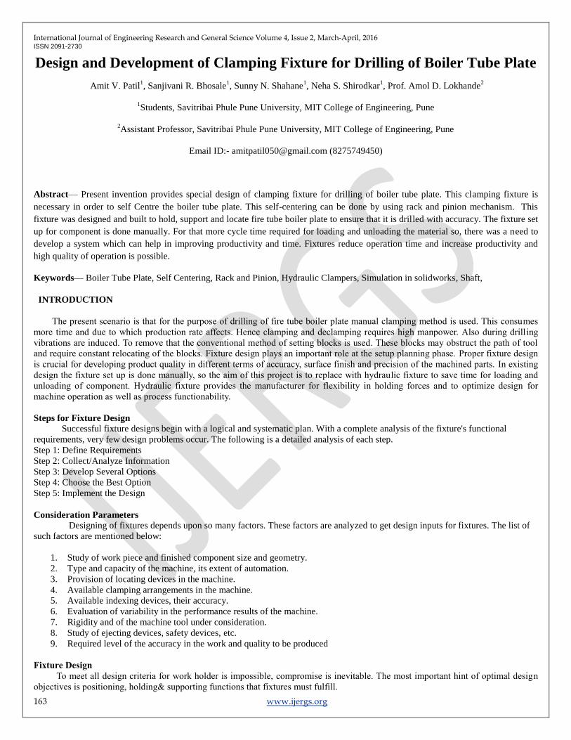
CENTERING OF TUBE PLATE
Initially centering of the plate is done manually. Perpendicular diameters are drawn approximately and center is plotted. Now the
plate is loosely clamped and tool is allowed to move from one end point of diameter towards the other and then the tool moves half of
the distance backward to obtain the center. If this center matches with the manually obtained center then machining is done by
tightening the clamping or else procedure is repeated unless and until exact center is obtained. During the drilling operation vibrations
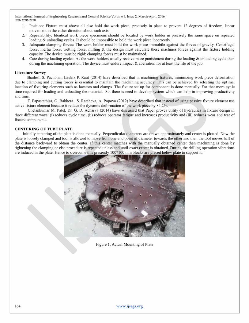
are induced in the plate. Hence to overcome this presently 100*100 mm blocks are placed below plate to support it.
Figure 1. Actual Mounting of Plate
International Journal of Engineering Research and General Science Volume 4, Issue 2, March-April, 2016 ISSN 2091-2730
165 www.ijergs.org
Figure 2. Manually adjusted Clamps
MAJOR PARTS OF THE SYSTEM
The following major parts are used in this system
1. Rack and Pinion
2. Shaft
3. Bearing
4. Coupling
5. Stand
6. Base plate
7. Clampers
DESIGN PROCEDURE
1. Design of Rack and Pinion: [7]
We have the standard rack and pinion pair available from ATALANTA RACK AND PINION Company.
Selection criteria are as follow:
Force required to pull the plate = weight of 2m diameter plate
W = volume × density × 9.81
W = ×7850×9.81= 5320 N
Step 1: Determining the Tangential Force
a =
[m/s²]
F = ((m×g×μ) + (m×a)) N
Step 2: From the given force select the standard rack and pinion pair and calculate Fperm.
F perm. =
The Condition F < F perm. Must be fulfilled.
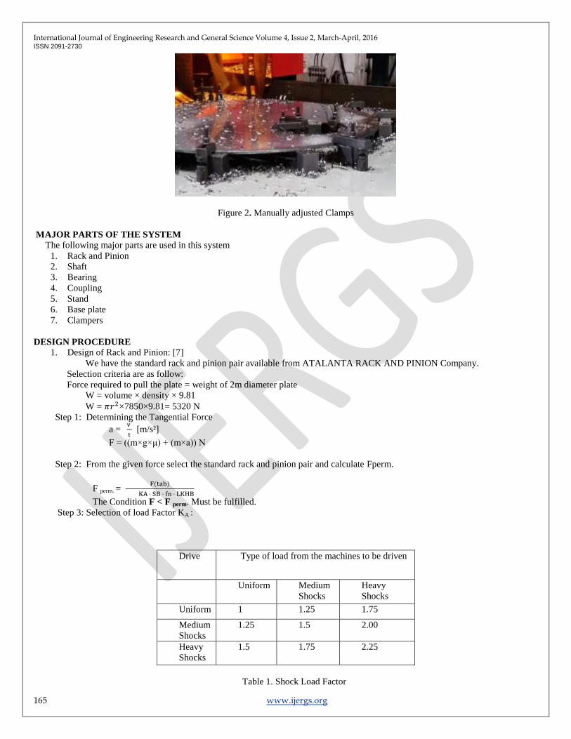
Step 3: Selection of load Factor KA :
Drive Type of load from the machines to be driven
Uniform Medium
Shocks
Heavy
Shocks
Uniform 1 1.25 1.75
Medium
Shocks
1.25 1.5 2.00
Heavy
Shocks
1.5 1.75 2.25
Table 1. Shock Load Factor
International Journal of Engineering Research and General Science Volume 4, Issue 2, March-April, 2016 ISSN 2091-2730
166 www.ijergs.org
Step 4: Safety Coefficient SB:
The safety coefficient should be taken as 1.1 to 1.4
(SB = 1.1 to 1.4).
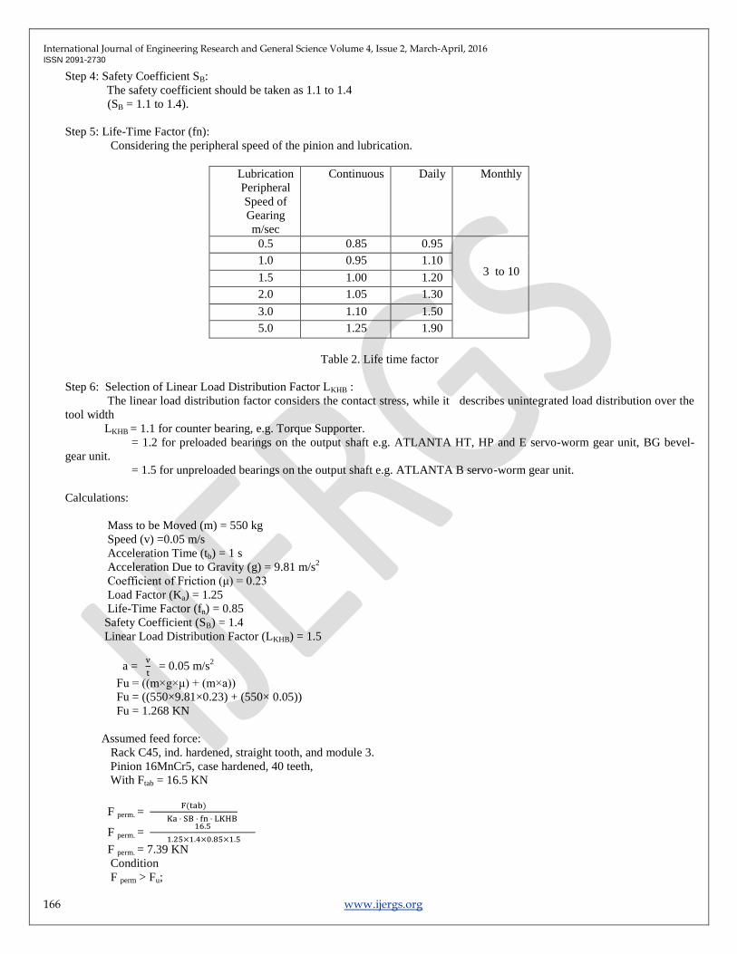
Step 5: Life-Time Factor (fn):
Considering the peripheral speed of the pinion and lubrication.
Lubrication
Peripheral
Speed of
Gearing
m/sec
Continuous Daily Monthly
0.5 0.85 0.95
3 to 10 1.0 0.95 1.10
1.5 1.00 1.20
2.0 1.05 1.30
3.0 1.10 1.50
5.0 1.25 1.90
Table 2. Life time factor
Step 6: Selection of Linear Load Distribution Factor LKHB :
The linear load distribution factor considers the contact stress, while it describes unintegrated load distribution over the
tool width
LKHB = 1.1 for counter bearing, e.g. Torque Supporter.
= 1.2 for preloaded bearings on the output shaft e.g. ATLANTA HT, HP and E servo-worm gear unit, BG bevel-
gear unit.
= 1.5 for unpreloaded bearings on the output shaft e.g. ATLANTA B servo-worm gear unit.
Calculations:
Mass to be Moved (m) = 550 kg
Speed (v) =0.05 m/s
Acceleration Time (tb) = 1 s
Acceleration Due to Gravity (g) = 9.81 m/s2
Coefficient of Friction (μ) = 0.23
Load Factor (Ka) = 1.25
Life-Time Factor (fn) = 0.85
Safety Coefficient (SB) = 1.4
Linear Load Distribution Factor (LKHB) = 1.5
a =
= 0.05 m/s
2
Fu = ((m×g×μ) + (m×a))
Fu = ((550×9.81×0.23) + (550× 0.05))
Fu = 1.268 KN
Assumed feed force:
Rack C45, ind. hardened, straight tooth, and module 3.
Pinion 16MnCr5, case hardened, 40 teeth,
With Ftab = 16.5 KN
F perm. =
F perm. =
F perm. = 7.39 KN
Condition
F perm > Fu;
International Journal of Engineering Research and General Science Volume 4, Issue 2, March-April, 2016 ISSN 2091-2730
167 www.ijergs.org
1.268 KN > 7.39 KN = > fulfilled
Result:
Rack 27 30 1001
Pinion 24 35 240 (case hardened). [4]
2. Design of Shaft
The shaft is designed using ASME code. According to this code, the permissible shear stress Ʈmax for the shaft without
keyways is taken as 30% of yield strength in tension or 18% of the ultimate tensile strength of the material, whichever is
minimum. If keyways are present, the above are reduced by 25%. Also, the bending and torsional moments are to be
multiplied by factors Kb and Kt respectively, to account for shock and fatigue.
Thus,
Ʈmax =
√ [(KB × M)
2 + (Kt
× T)
2]
Where,
Kb = combined shock and fatigue factor applied to bending moment
Kt = combined shock and fatigue factor applied to torsional moment
Step 1: Selection of material for shaft.
The material selected for the shaft is C40 [7]
The values of the ultimate tensile strength and yield strength are as follows:
Sut = 640N/mm2
Syt = 380N/mm2
Step 2: Calculation of permissible shear stress
Allowable stress = .75×.3×Syt or .75×.18×Sut
= 85.5 N/mm2 or 86.4 N/mm
2
Hence, permissible shear stress is 85.5 N/mm2 …. Minimum value is taken.
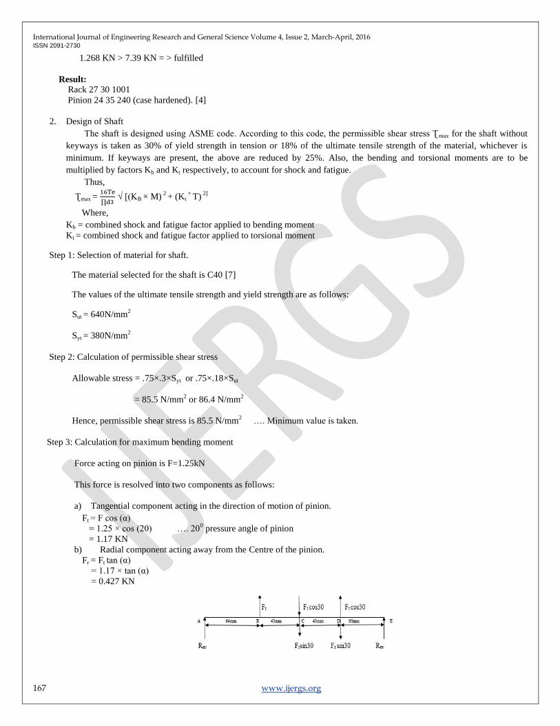
Step 3: Calculation for maximum bending moment
Force acting on pinion is F=1.25kN
This force is resolved into two components as follows:
a) Tangential component acting in the direction of motion of pinion.
Ft = F cos (α)
= 1.25 × cos (20) …. 200 pressure angle of pinion
= 1.17 KN
b) Radial component acting away from the Centre of the pinion.
Fr = Ft tan (α)
= 1.17 × tan (α)
= 0.427 KN
International Journal of Engineering Research and General Science Volume 4, Issue 2, March-April, 2016 ISSN 2091-2730
168 www.ijergs.org
Figure 3. Vertical force diagram
∑Fy=0
Therefore, from vertical force diagram,
Fr - Frsin30 - Frsin30 + Ftcos30 – Ftcos30 + RAV + REV = 0
0.427- 2×(0.427)×sin30 + RAV + REV = 0
RAV + REV = 0 …. (1)
Consider the moments about ‘A’.
∑Ma = 0
Fr × 64 – (Ftcos30 + Frsin30) × 107 + (Ftcos30 - Frsin30) × 150 + REV ×210 = 0
Thus,
REV = -0.076 kN
RAV = 0.076 kN
Bending moments at different points are as follows:
MBV = RAV × 64
= 4.864 kN-mm
MCV = RAV × 107 + Fr × 43
= 26.514 kN-mm
MDV = REV × 60
= - 4.595 kN-mm
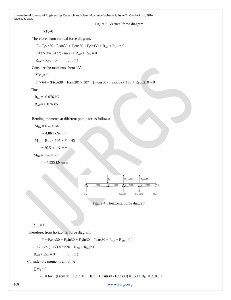
Figure 4. Horizontal force diagram
∑Fy=0
Therefore, from horizontal force diagram,
-Ft + Frcos30 + Ftsin30 + Ftsin30 – Frcos30 + RAH + REH = 0
-1.17 - 2× (1.17) × sin30 + RAH + REH = 0
RAH + REH = 0 …. (1)
Consider the moments about ‘A’.
∑Ma = 0
-Ft × 64 + (Frcos30 + Ftsin30) × 107 + (Ftsin30 - Frcos30) × 150 + REH × 210 = 0
International Journal of Engineering Research and General Science Volume 4, Issue 2, March-April, 2016 ISSN 2091-2730
169 www.ijergs.org
Thus,
REH = -0.28 KN
RAH = 0.28 KN
Bending moments at different points are as follows:
MBH = RAH × 64
= 17.92 kN-mm
MCH = RAH × 107 - Ft × 43
= -20.35 kN-mm
MDH = REH × 60
= - 16.8 kN-mm
Resultant bending moments
MB = √ [(MBH) 2
+ (MBV) 2]
= 1.856 kN-mm
MC = √ [(MCH) 2
+ (MCV) 2]
= 33.42 kN-mm
MD = √ [(MDH) 2
+ (MDV) 2]
= 17.41 kN-mm
Therefore the highest total bending moment is occurring at point ‘C’.
Hence M = 33.42 kN-mm
Step 4: Calculation of torsional moment
Torque acting on the shaft is
T = Ft × r
= 0.0702 × 10³ KN-mm
Step 5: Calculation of equivalent torsional moment
For gradually loaded rotating shaft
Kb = 1.5 and Kt = 1 …. V. B. Bhandari Pg. No.334
Thus the equivalent torque is
Te = √ [(KB × M) 2
+ (Kt × T) 2]
= 86.26 kN-mm
Step 6: Verification of safety of shaft
International Journal of Engineering Research and General Science Volume 4, Issue 2, March-April, 2016 ISSN 2091-2730
170 www.ijergs.org
The allowable torsional stress is given as
Ʈall =
= 10.24 N/mm2 > 85.5
Therefore design is safe.
3. Design of key
Step 1: Selection of material
C50 is selected as material for key
Sut = 520 N/mm2
Syt = 340 N/mm2
Step 2: Determination of dimensions of the key
For diameter of 35mm, the dimensions of keys are 10mm × 8 mm. [8]
Step 3: Permissible compressive and shear stresses
σc =
= 340/3
= 113.33 N/mm2
According to maximum shear stress theory of failure,
Ssy = 0.5 Syt
= 0.5 × 340
= 170 N/mm2
Ʈ =
= 170/3
= 56.67 N/mm2
Step 4: Determination of induced compressive and shear stress
σc =
=
= 33.42 N/mm2 < 113.33 N/mm
2
Ʈ =
=
= 13.37 N/mm2 < 56.67 N/mm
2
Hence, the design of key is safe.
4. Design of Bearings:
International Journal of Engineering Research and General Science Volume 4, Issue 2, March-April, 2016 ISSN 2091-2730
171 www.ijergs.org
Procedure for selection of bearing from manufacturing catalogue
Step 1:
Calculate i) radial (fr) and axial forces (fa) acting on the bearings
ii) Diameter of shaft (d)
iii) Speed of shaft (n)
Step 2:
Select the type of bearing for the given application.
Step 3:
Calculate the values of X and Y , the radial and thrust factors, from the catalogue. These values depends upon ratios,(fa/fr)
and (fa/C0).The selection therefore, done by trial and error method.
To begin with, a bearing of light series, such as 60,is selected for the given diameter of the shaft and the values of C0 is
found from the catalogue.
Step 4:
Calculate the equivalent dynamic load from the equation.
P=X × fr +Y × fa
Step 5:
Make a decision about the expected bearing life and express the life L10 in million revolutions.
L10 = 60 ×n ×L10h
106
L10 = 60 ×10 ×30000
106
=18 millions
Step 6:
C = P × (L10)1/a
a=3 (ball bearing)
C= 360.49 × (18)1/3
=944.7525 N
Cr =19613.3
So, Cr > C
So selected bearing is safe
Step 7:
Referring the SKF manufacturing catalogue the selected bearing no is 6207[6]
Dimensions of the bearing
Inner diameter of shaft =35mm
Outer diameter of shaft=72mm
International Journal of Engineering Research and General Science Volume 4, Issue 2, March-April, 2016 ISSN 2091-2730
172 www.ijergs.org
Thickness of bearing =17mm
5. Design of coupling:[7]
The basic procedure for finding out the dimensions of the rigid flange coupling consists of the following steps:
Shaft diameter: Calculate the shaft diameter
Dimensions of flanges: Calculate the dimensions of the flange by the following empirical equations:
dh = 2d
Lh = 1.5 d
D = 3 d
t =.5 d
t1 = .25 d
dr = 1.5 d
Do = (4d +2t1)
The torsional shear stress in the hub can be calculated by considering it as a hollow shaft subjected to torsional moment M t.
The inner and outer diameters of the hub are d and dh respectively. The torsional shear stress in the hub is given by,
Ʈ =
J = ∏ (dh4-d
4)/32
r = dh/2
Shaft diameter = 35 mm
Dimensions of flange are given by following empirical equations:
dh = 2d = 70mm
Lh = 1.5 d =52.5mm
D = 3 d = 105mm
t = .5 d = 17.5 mm
t1 = .25 d = 8.75 mm
dr = 1.5 d = 52.5 mm
Do = (4d +2t1) = 157.5 mm
For d < 40mm, N = 3
6. Design of hydraulic clampers [8]
International Journal of Engineering Research and General Science Volume 4, Issue 2, March-April, 2016 ISSN 2091-2730
173 www.ijergs.org
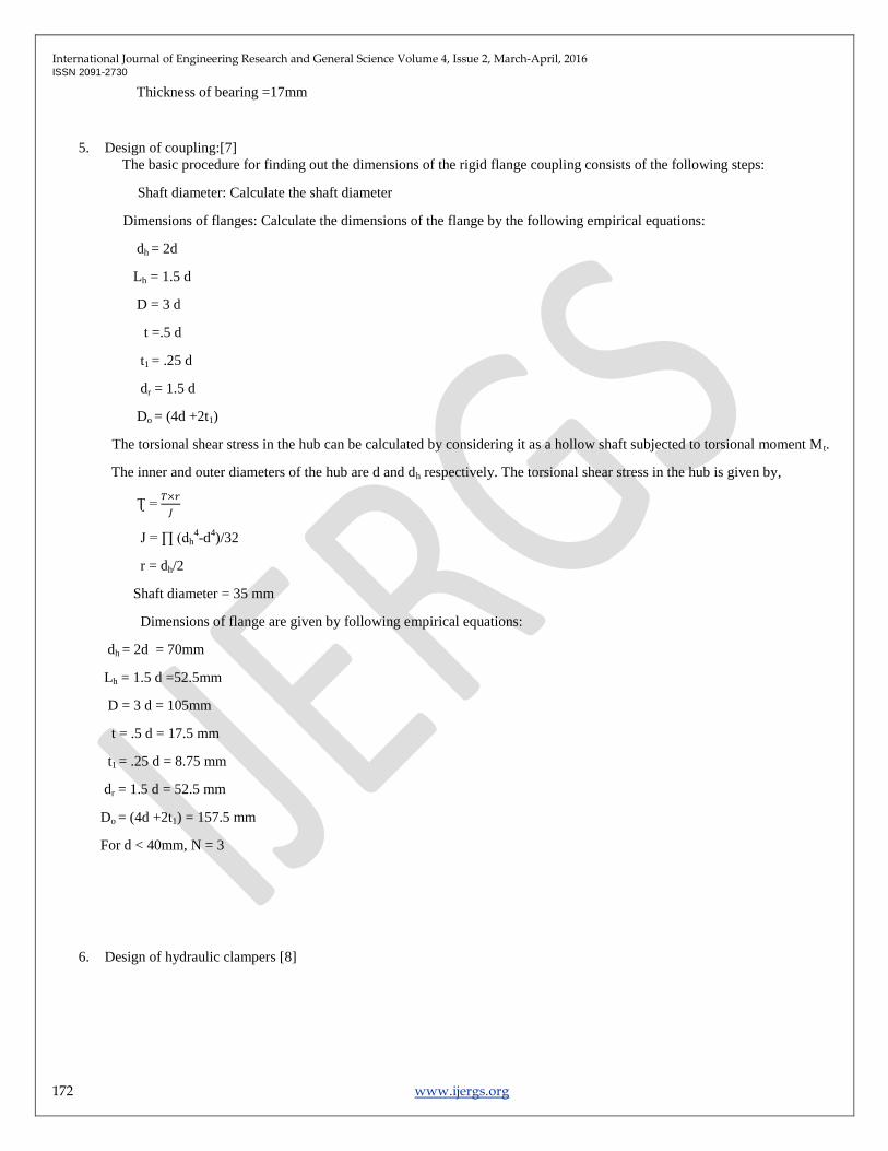
Figure 5. Design of hydraulic clampers
Table 3. Clamper Specifications
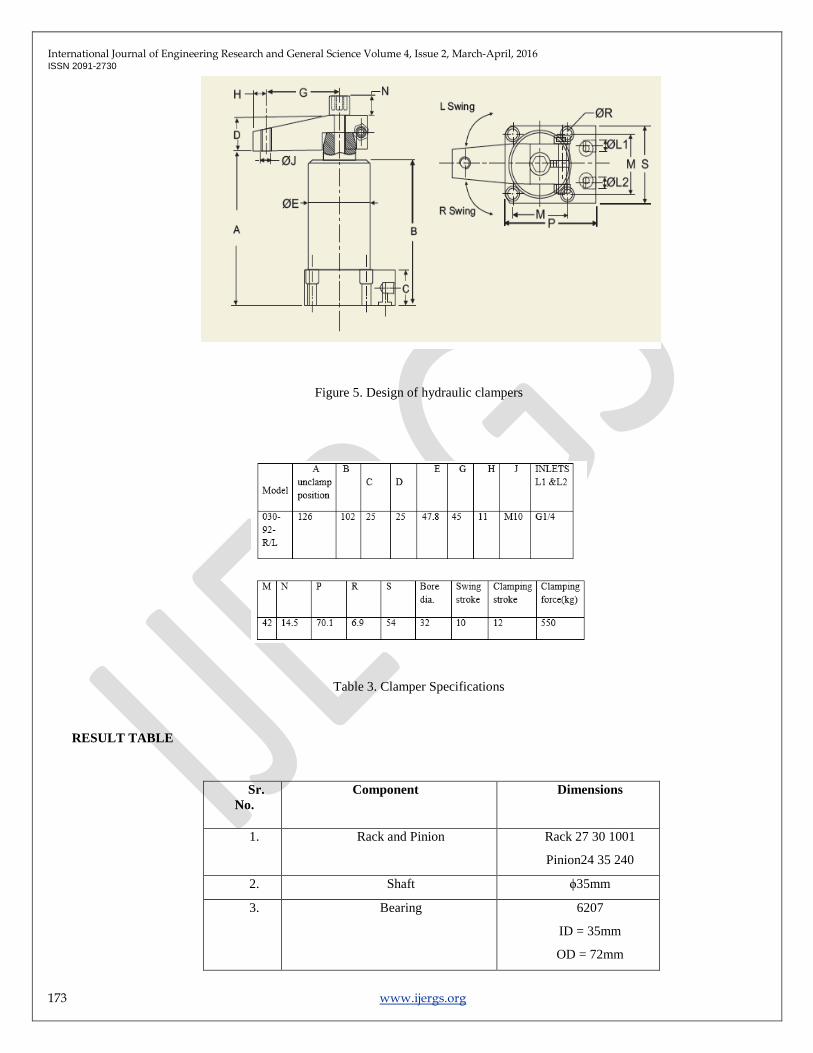
RESULT TABLE
Sr.
No.
Component
Dimensions
1. Rack and Pinion Rack 27 30 1001
Pinion24 35 240
2. Shaft ϕ35mm
3. Bearing 6207
ID = 35mm
OD = 72mm
International Journal of Engineering Research and General Science Volume 4, Issue 2, March-April, 2016 ISSN 2091-2730
174 www.ijergs.org
Thickness=17mm
4. Coupling dh=70mm,Lh=52.5mm
D=105mm,t=17.5 mm
t1 = 8.75 mm
5. Stand 15mm
Table 4. Component Specification
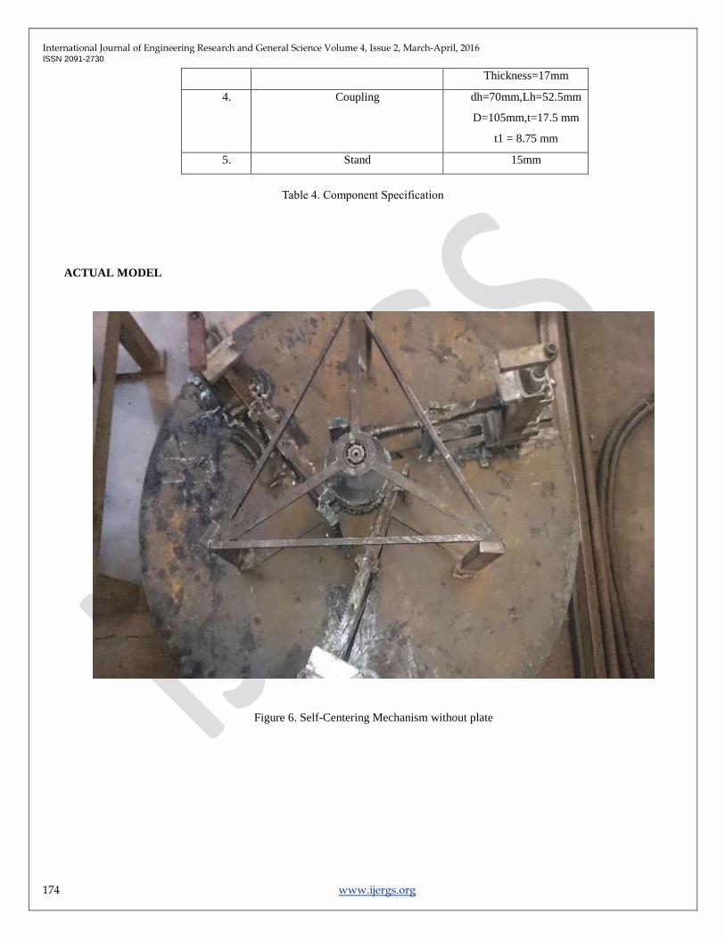
ACTUAL MODEL
Figure 6. Self-Centering Mechanism without plate
International Journal of Engineering Research and General Science Volume 4, Issue 2, March-April, 2016 ISSN 2091-2730
175 www.ijergs.org
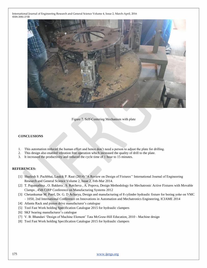
Figure 7. Self-Centering Mechanism with plate
CONCLUSIONS
1. This automation reduced the human effort and hence don’t need a person to adjust the plate for drilling.
2. This design also enabled vibration free operation which increased the quality of drill to the plate.
3. It increased the productivity and reduced the cycle time of 1 hour to 15 minutes.
REFERENCES:
[1] Shailesh S .Pachbhai, Laukik P. Raut (2014) ―A Review on Design of Fixtures’’ International Journal of Engineering
Research and General Science Volume 2, Issue 2, Feb-Mar 2014.
[2] T. Papastathisa , O. Bakkera , S. Ratcheva , A. Popova, Design Methodology for Mechatronic Active Fixtures with Movable
Clamps , 45th CIRP Conference on Manufacturing Systems 2012
[3] Chetankumar M. Patel, Dr. G. D Acharya, Design and manufacturing of 8 cylinder hydraulic fixture for boring yoke on VMC
– 1050, 2nd International Conference on Innovations in Automation and Mechatronics Engineering, ICIAME 2014
[4] Atlanta Rack and pinion drive manufacturer’s catalogue
[5] Tool Fast Work holding Specification Catalogue 2015 for hydraulic clampers
[6] SKF bearing manufacturer’s catalogue
[7] V. B. Bhandari ‘Design of Machine Element’ Tata McGraw-Hill Education, 2010 - Machine design
[8] Tool Fast Work holding Specification Catalogue 2015 for hydraulic clampers