indiana geospatial coordinate system (ingcs) · the indiana geospatial coordinate system (ingcs)...
TRANSCRIPT

Indiana Geospatial Coordinate System (InGCS)
Matthew G. Badger, PS Survey Project Manager, Lochmueller Group
INDOT Consultant
July 29, 2015

The Indiana Geospatial Coordinate System (InGCS)
Bridging the data gap between Land Surveying and the larger geospatial community.
…like having your cake, and eating it too.

Indiana Geospatial Coordinate System
Indiana’s Geospatial Community Photogrammetry, Remote Sensing and GIS Professionals Land Surveyors Civil Engineers Construction Industry Military Police, Fire Departments Emergency Medical Staff Agriculture The General Public (on-board GPS, OnStar, etc.) Geocachers Etc., etc.

Indiana Geospatial Coordinate System
Geospatially Friendly Work Environment
At the end of the (work) day, all sectors/industries have their own different “needs”, necessitating different map projections. Being geospatially-friendly involves the ability to accurately, precisely, quickly and seamlessly share georeferenced data with the rest of the community.

Indiana Geospatial Coordinate System
Geospatially Friendly Work Environment
Consider the following: What’s the benefit to the geospatial community of having Land
Surveying data that’s very representative of ground-measured distances, if it’s difficult or cumbersome to replicate the results?
What is the benefit to Land Surveying or Civil Engineering projects having geospatial data that is very neat, clean, has well-documented metadata and can easily be transformed or reprojected from one reference frame to another if it is not representative of ground surface/terrestrial-based measurements?

Indiana Geospatial Coordinate System
Land Surveying and the larger Geospatial Community
Can we all really work well together, without sacrificing our respective roles or identities or the quality of our work?
YES! …but how? (published) Map Projections!

Indiana Geospatial Coordinate System
Map Projections
Emphasis placed on the plural case of “Projection(s)” Why do we have more than one map projection? Isn’t the Earth flat???

Indiana Geospatial Coordinate System
Map Projection-Flat Earth
If the Earth were indeed flat, a single map design could satisfy all mapping applications.
No distortion! One bearing system!
Convergence Angles One system of grid coordinates! Grid=Ground
Grid Scale Factor Elevation Scale Factor Combined Scale Factor

Indiana Geospatial Coordinate System
Map Projection-Flat Earth (?)
But, nevertheless…
It seems that the Earth isn’t flat after all.

Indiana Geospatial Coordinate System
Map Projections-Round Earth
With the Earth being round (oblate spheroid), we turn to map projections to provide us with flat, developed surfaces to represent our products: Aerial Photography Topographic Maps Land Survey Plats Design Plans Tax maps Etc., etc.
Indiana Geospatial Coordinate System
Existing Map Projections
Breakthroughs in positioning technology have indeed increased the ease of accurately determining the geographic positions of points on, above or below the surface of the Earth.
Many users outside of Land Surveying and Civil Engineering may only be concerned with absolute positioning, rather than relative positioning (other than the selecting the quickest route from “here” to “there”).
Indiana Geospatial Coordinate System
Existing Map Projections
So with all the different sectors/industries different needs, what’s the best map projection for each within Indiana?
As the saying goes, one man’s trash is another man’s treasure

Indiana Geospatial Coordinate System
Existing Map Projections
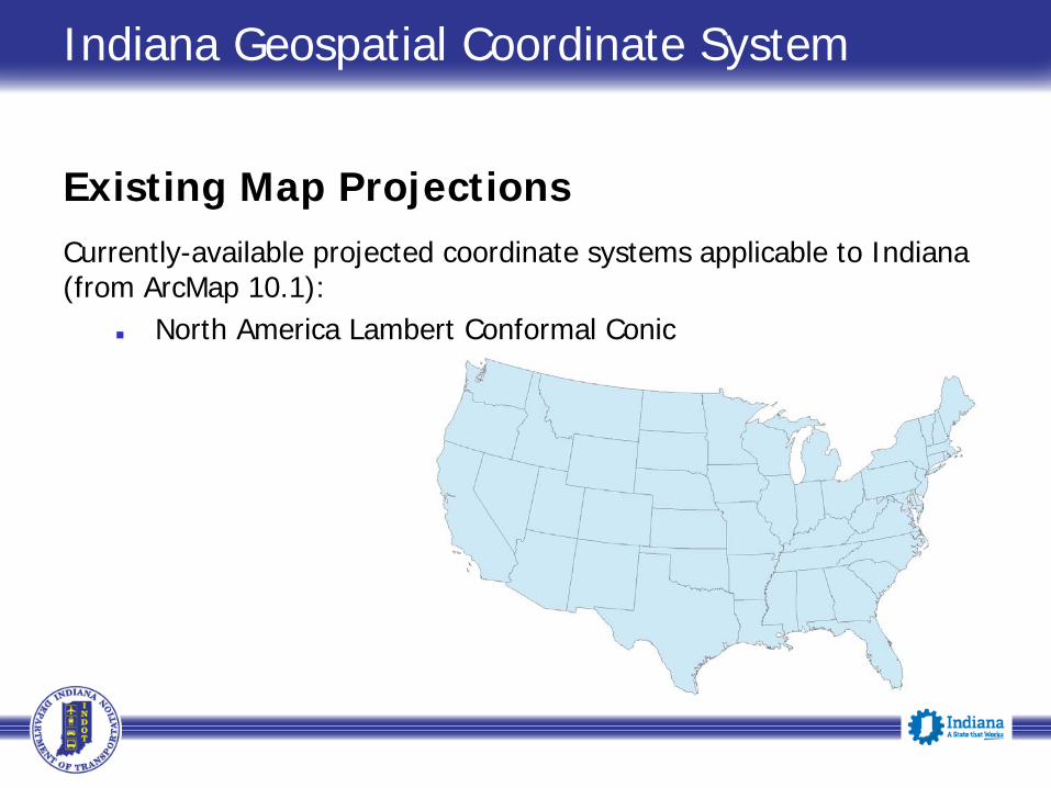
Currently-available projected coordinate systems applicable to Indiana (from ArcMap 10.1):
World Mercator
Indiana Geospatial Coordinate System
Existing Map Projections
Currently-available projected coordinate systems applicable to Indiana (from ArcMap 10.1):
North America Lambert Conformal Conic
Indiana Geospatial Coordinate System
Existing Map Projections
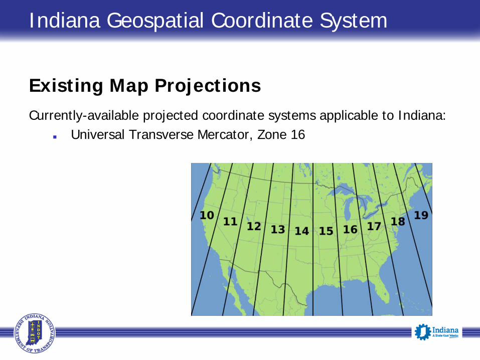
Currently-available projected coordinate systems applicable to Indiana: Universal Transverse Mercator, Zone 16

Indiana Geospatial Coordinate System
Existing Map Projections
Currently-available projected coordinate systems applicable to Indiana:
Indiana State Plane East Zone (1301) Indiana State Plane West Zone (1302)

Indiana Geospatial Coordinate System
Existing Map Projections
Currently-available projected coordinate systems applicable to Indiana: Illinois East Zone Kentucky Single Zone Kentucky South Zone Kentucky North Zone Ohio South Zone Ohio North Zone Michigan South Zone
There are no GNSS signal jammers or Zone walls at State Lines!
The software in data collectors keep on calculating…

Indiana Geospatial Coordinate System
Map Projections
In the United States, we typically think of three types of map projections for our industry’s workflow
Transverse Mercator Lambert Conformal Conic Oblique Mercator (Hotine)

Indiana Geospatial Coordinate System
Map Projections
Examples: Universal Transverse Mercator
Developed in the 1940’s by the Corps of Engineers, U.S. Army, primarily for artillery use
All Zones were Transverse Mercator
6° of Longitude per Zone Maximum grid scale factor
of 1:2,500 Indiana lies within Zone 16

Indiana Geospatial Coordinate System
Map Projections
Examples: U.S. State Plane Coordinate System
Developed in the 1930’s by the USC&GS
Maximum grid scale factor of 1:10,000 Indiana’s SPC System grid
scale factors were set to 1:30,000

Indiana Geospatial Coordinate System
Map Projections
Both of these systems achieved their grid scale factor goals.
What is a grid scale factor and how does it apply to measurements made on/along the terrain surface?

Indiana Geospatial Coordinate System
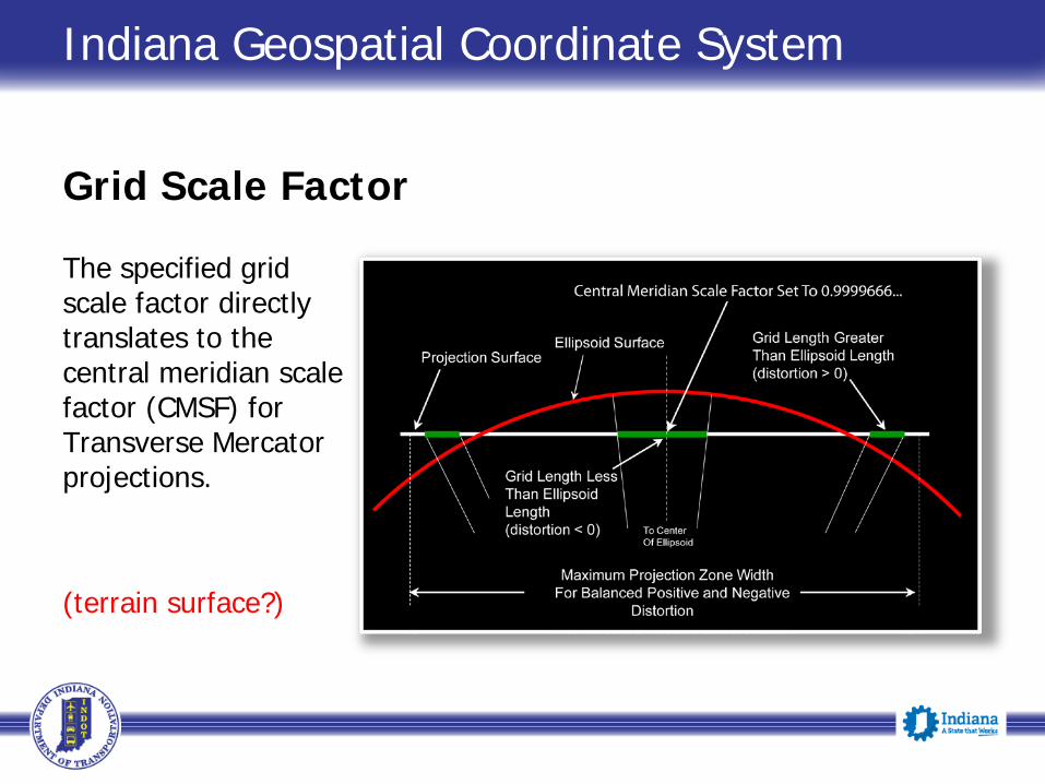
Grid Scale Factor
A grid scale factor is the relationship of the length of a line on the ellipsoid and its extent when projected on to the developed mapping surface. UTM: 1’ in 2,500’ (ellipsoid vs. map) SPCS: 1’ in 10,000 (ellipsoid vs. map) (terrain surface unaccounted for)
Indiana Geospatial Coordinate System
Grid Scale Factor
The specified grid scale factor directly translates to the central meridian scale factor (CMSF) for Transverse Mercator projections. (terrain surface?)

Indiana Geospatial Coordinate System
Grid Scale Factor
UTM Grid Scale Factor 1:2,500 = (1-(1/2,500)) = 0.9996 (exact)(CMSF) IN State Planes Grid Scale Factor (both zones have same GSF) 1:10,000 = (1-(1/30,000)) = 0.999966…(CMSF)
(still no mention of terrain surface…)

Indiana Geospatial Coordinate System
Grid Scale Factor
Remember, the designers of the U.S. State Plane Coordinate System in the 1930’s and the UTM System in the 1940’s did not have the latest and greatest in solid state drives, high-end graphics cards, 5th Generation Intel Core Processors, dual or triple monitors, etc., etc.

Indiana Geospatial Coordinate System
Grid Scale Factor
The designers of the U.S. State Plane Coordinate System in the 1930’s and the UTM System in the 1940’s only had desks, pencils, paper, slide rules, logarithm table books, etc. to perform the necessary computations! They rightfully made use of the global terrain surface available at that time (Clarke ellipsoid/spheroid of 1866) to compute map projections that provided the desired results for the projects of that era.

Indiana Geospatial Coordinate System
Current Date: 2015 A.D.
Here we are now, approximately 80 years after the inception of the State Plane Coordinate System.
Still driving automobiles on roads (no Jetsons-style flying auto’s) Still using the bench marks established by the USC&GS Not really making use of steel chains anymore Not climbing up in any of Jasper Bilby’s towers anymore

Indiana Geospatial Coordinate System
Current Date: 2015 A.D.
Technological advancements in measurement techniques and processing of network adjustments since the 1930’s and 40’s have increased dramatically!
Computers Digital Levels Total Stations with “lasers” Global Positioning System/Global Navigation Satellite System LIDAR (airborne, marine, mobile & terrestrial) UAS Close-range photogrammetry Next???
Indiana Geospatial Coordinate System
Geospatial Projects: Present & Future
For the geospatial projects that have yet to begin, many of them have requirements, guidelines or preferences that the existing UTM System or SPC System can satisfy.
U.S. Army Corps of Engineers U.S. Department of the Interior/BLM U.S. Department of Agriculture U.S. Forest Service Federal Emergency Management Agency Indiana Department of Natural Resources Indiana Statewide Orthophotography
Indiana Geospatial Coordinate System
Geospatial Projects: Present & Future
There are many other types of geospatial projects that have yet to begin that may have requirements, guidelines or preferences that the existing UTM System or SPC System cannot satisfy.
? Now what?
What have we done in the somewhat recent past…since GPS?

Indiana Geospatial Coordinate System
Geospatial Projects: Past, Present & Future
Focus Land Surveying and Civil Engineering

Indiana Geospatial Coordinate System
Land Surveying and Civil Engineering in Indiana, pre- GPS/GNSS
Before the availability of High Accuracy Reference Networks (HARN) or Real-Time (GNSS) Networks (RTNs) and the widespread use of Survey-grade GPS/GNSS equipment, it was NOT easy or cost effective for Land Surveyors to be able to either accurately or precisely relate their projects to Geodetic Datums, such as NAD 83.

Indiana Geospatial Coordinate System
Land Surveying and Civil Engineering in Indiana, pre- GPS/GNSS
Most projects were based upon “local” or arbitrary coordinate systems. Origin of coordinates: N 5,000 E 5,000 at a certain physical
monument (Section Corner, highway alignment, etc.) Bearings based upon the direction to another certain physical
monument (assumed bearing, pocket compass, deed, etc.) Terrestrial measurements (total station traversing) May not have matched any other adjacent project in bearings or
coordinate values

Indiana Geospatial Coordinate System
Land Surveying and Civil Engineering in Indiana, post- GPS/GNSS
With the advent of GPS/GNSS, High-Accuracy Reference Networks and Real-Time (GNSS) Networks, Land Surveyors have the ability to quickly and accurately tie to Geodetic Datums (e.g., NAD 83) and available map projections (State Plane systems, UTM, etc.).
(Work) life should be great now, right? Maybe…maybe not.

Indiana Geospatial Coordinate System
Land Surveying and Civil Engineering in Indiana, post- GPS/GNSS
Another issue is at hand.
Indiana State Plane East or West Zone or UTM 16 Grid Inverses ≠ Horizontal ground distances (in most cases)
(a.k.a., “Grid versus Ground”)

Indiana Geospatial Coordinate System
Land Surveying and Civil Engineering in Indiana, post- GPS/GNSS
Grid versus Ground in Indiana:
UTM 16: +/- 400 ppm (2.1’ per mile)(1:2,500) IN SPCS: Upwards of 75 ppm (0.4’ per mile)(1:13,300)

Indiana Geospatial Coordinate System
Land Surveying and Civil Engineering in Indiana, post- GPS/GNSS
The magnitude of these “Grid versus Ground” differences does not make it impossible to perform the typical Land Surveying, Civil Engineering or Construction projects encountered by practitioners in the Government and Private Sector.

Indiana Geospatial Coordinate System
Land Surveying and Civil Engineering in Indiana, post- GPS/GNSS
BUT, basing projects upon these systems, while working with the advanced measuring equipment available today and using prudent measurement techniques and network adjustments, is somewhat like walking around with boots a few sizes too big.

Indiana Geospatial Coordinate System
Land Surveying and Civil Engineering in Indiana, post- GPS/GNSS
A widely-used methodology by Land Surveyors to utilize GPS/GNSS but still have “acceptable” grid-versus-ground differences…
Scale Each Project To Ground

Indiana Geospatial Coordinate System
Scaling Each Project to Ground
What are the advantages of scaling each project to ground?
The mapping planes are effectively raised or lowered to approximate the (local) terrain surfaces across the limits of each project
(Scaled) Grid Inverses ≈ Horizontal ground distances

Indiana Geospatial Coordinate System
Scaling Each Project to Ground
Typically has been prepared in two different methods:
Local or Arbitrary Systems Tied to NSRS?…maybe just an autonomous/”here” position
at the base station Assign random coordinate values (N 5,000 E 5,000) at a
certain physical monument Bearings based upon ??? Still might not match other adjacent projects Works well within itself!
Indiana Geospatial Coordinate System
Scaling Each Project to Ground
Typically has been prepared in two different methods:
Modify existing defined system (UTM, State Plane) Still may not be tied to NSRS…but more likely so. Coordinate values
Scale from origin (0,0) Reassign random values at physical monument Truncate coordinates at physical monument
Bearings typically left alone (not rotated) Still might not match other adjacent projects Works well within itself!

Indiana Geospatial Coordinate System
Scaling Each Project to Ground
What are the disadvantages of scaling each project to ground?
Time consuming! Designing each and every new site Checking computations Making sure all office & field devices have the calibration file Documenting calibration (internal filing and public record) Subsequent practitioners:
Discovery of the system Recreate the calibration in their own software and
distribute to office & field devices Field verifications

Indiana Geospatial Coordinate System
Scaling Each Project to Ground
What are the disadvantages of scaling each project to ground?
It’s typically only effective for smaller, site-specific projects Parameters for each STG project are not made commercially-
available in geospatial software platforms Parameters may have been incorrectly documented, or not
documented at all What happens if all local control is disturbed or destroyed?

Indiana Geospatial Coordinate System
Scaling Each Project to Ground
What are the disadvantages of scaling each project to ground?
Numerous!...and increasing. Small regions (Section, Town, City) Counties Statewide Nationwide
Overlaying aerial photography?! Arbitrary systems may resort to fitting to photo-id features Modified UTM or SPC systems (scale, translate, rotate?)

Indiana Geospatial Coordinate System
Scaling Each Project to Ground The disadvantages of scaling each project to ground seem to far outweigh the advantages. Let’s stop scaling each project to ground! Let’s start using Low Distortion Projections (LDP’s)!
Indiana Geospatial Coordinate System
Low Distortion Projections
What are LDP’s?
LDP’s have the same general flavor/purpse of their projection siblings (State Plane, UTM, Continental, World):
To portray the curved surface of the Earth on a flat surface To satisfy the stated goals of the target users

Indiana Geospatial Coordinate System
Low Distortion Projections
As the name itself implies, LDP’s are map projections that have low or minimized distortion across the design region.
Distortion in still unavoidable…but LDP’s can provide more tolerable distortions to geospatial projects.
Transverse Mercator Lambert Conformal Conic Oblique Mercator

Indiana Geospatial Coordinate System
Low Distortion Projections
Two types of Distortion Angular: Convergence angle for conformal projections Linear: Difference between grid inverses (map distance) and
corresponding ground/horizontal distances
Transverse Mercator Lambert Conformal Conic Oblique Mercator

Indiana Geospatial Coordinate System
Low Distortion Projections
Distortions less that UTM or SPCS Angular: Central Meridians are typically closer to the design
regions than the CM’s of UTM or SPCS Linear: The mapping surface is designed to approximate the
design region’s terrain surface
Transverse Mercator Lambert Conformal Conic Oblique Mercator

Indiana Geospatial Coordinate System
Low Distortion Projections If we limit our selection of the conformal map projections Transverse Mercator, Oblique Mercator or the Lambert Conformal conic projection, conformal map projections, we will be making use of the three projection types used by the USC&GS to develop the United States’ State Plane Coordinate System…what most all geospatial users are accustomed to.
Transverse Mercator Lambert Conformal Conic Oblique Mercator

Indiana Geospatial Coordinate System
Low Distortion Projections Yes, they’re like mini-State Plane Zones.
Transverse Mercator Lambert Conformal Conic Oblique Mercator

Indiana Geospatial Coordinate System
Low Distortion Projections LDP’s versus Scaling Each Project to Ground?
The concept of LDP’s and “scaling each project to ground” are similar in that both developed mapping surfaces have been lowered or raised to approximate the terrain surface across the designated region.

Indiana Geospatial Coordinate System
Low Distortion Projections
Advantages of LDP’s over “scaling each project to ground”: Time savings
Quick selection of system in software No design time No design-validation time Not constantly verifying office & field devices are up-to-date Documentation (internal and public record) time reduced to
the same as documenting UTM or State Plane Subsequent practitioners time reduced to the same as
following UTM or State Plane projects

Indiana Geospatial Coordinate System
Low Distortion Projections
Advantages of LDP’s over “scaling each project to ground”: Directly tied to the National Spatial Reference System (NSRS) Not anchored/dependent upon local, physical monuments Intended to cover much larger regions Can be commercially available With software platforms that provide for “reprojections on-the-
fly”, files can be quickly imported from different, published coordinate systems and/or files can be exported and reprojected by other users in their software Aerial photography Polygons, Polylines, Points Etc.

Indiana Geospatial Coordinate System
Low Distortion Projections
MAJOR ADVANTAGE OF LDP’s TO THE GEOSPATIAL COMMUNITY As long as the LDP-based (source) Survey data has been properly georeferenced and the data-sharing parties have geospatial software that supports reprojections on-the-fly, data can be seamlessly shared across industries and sectors (Government and Private), regardless of the destination predefined coordinate system (UTM, State Plane).

Indiana Geospatial Coordinate System
Low Distortion Projections
What other States and Departments of Transportation are using Low Distortion Projections (LDPs)?:
Minnesota Wisconsin Oregon Iowa ???
Indiana Geospatial Coordinate System
InGCS: Design Goals
Summary of the stated goals of the InGCS: Geodetic Datum: reference all projections to the National Spatial
Reference System, NAD 83 (2011, +)… Projection Type: Transverse Mercator (all)

Indiana Geospatial Coordinate System
InGCS: Design Goals
Summary of the stated goals of the InGCS: Linear Units: define all False Northings and Easting in meters that
coincide with even-foot U.S. Survey Foot conversions False Northing: 36,000 m=118,110- U.S. Survey Feet False Easting: 240,000 m=787,400- U.S. Survey Feet
Indiana Geospatial Coordinate System
InGCS: Design Goals
Summary of the stated goals of the InGCS: Angular Units: define latitude of grid origin and central meridians at
even 3-minute intervals for exact conversion to decimal degrees at two decimal places Marion County Example:
Lat. of Grid Origin: 39°18'00" N=39.30°N Central Meridian: 86°09'00" W=86.15°W

Indiana Geospatial Coordinate System
InGCS: Design Goals
Summary of the stated goals of the InGCS: Central Meridian Scale Factors: Define to exactly six decimal places
Marion County Example: CMSF=1.000031

Indiana Geospatial Coordinate System
InGCS: Design Goals
Summary of the stated goals of the InGCS: Preferred Linear Distortion Budget:
5 ppm’s (≈0.03’/mile) at the 95% level 10 ppm’s (≈0.05’/mile) at the 99% level

Indiana Geospatial Coordinate System
InGCS: Design Goals
Summary of the stated goals of the InGCS: Zone Limits/Boundaries: Each County will be its own “zone” Attempt to group as many Counties together
Keep a County autonomous if combining an adjacent County would otherwise cause it to exceed the distortion budget
Even if an autonomous County already exceeded distortion budget, keep it autonomous if combining an adjacent County would otherwise cause the distortion to “substantially” increase
Numerical Definitions: (see Handbook when published)

Indiana Geospatial Coordinate System
InGCS: Design Results
Indiana has 92 Counties. From stated goals, this yields 92 zones.
When comparing the projection parameters of the 92 Zones, there are 57 distinct sets of projection parameters.
InGCS Linear Distortion Statistics Average ≈ 2.6 ppm’s (0.014’/mile) Worst sampled linear distortion:
23.4 ppm (≈0.12’/mile)

Indiana Geospatial Coordinate System
What’s next???
INDOT is working towards the following roll-out of the InGCS: Having the parameters included in the European Petroleum Survey
Groups (EPSG’s) Geodetic Parameter Dataset Making the projection parameters available on INDOT’s website for
geospatial software providers and other users to view and download Coordinating with many geospatial software providers to include the
InGCS in their platforms Writing a “Handbook and User Guide” Rewriting the appropriate Sections of the INDOT Design Manual Seminars, workshops, conferences, etc.

Indiana Geospatial Coordinate System
Questions?