exercise 1: introduction to transducers - lab-volt manual facet by lab-volt 11 transducer...
TRANSCRIPT
Student Manual
10 FACET by Lab-Volt
Familiarization Transducer Fundamentals
Exercise 1: Introduction to Transducers
EXERCISE OBJECTIVE
When you have completed this exercise, you will be able to describe the basic operation of transducer
devices. You will verify your results by measuring basic transducer output parameters.
DISCUSSION
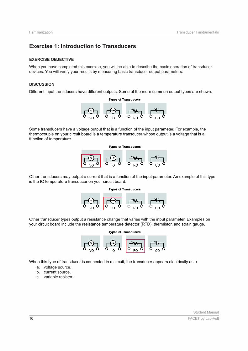
Different input transducers have different outputs. Some of the more common output types are shown.
Some transducers have a voltage output that is a function of the input parameter. For example, the
thermocouple on your circuit board is a temperature transducer whose output is a voltage that is a
function of temperature.
Other transducers may output a current that is a function of the input parameter. An example of this type
is the IC temperature transducer on your circuit board.
Other transducer types output a resistance change that varies with the input parameter. Examples on
your circuit board include the resistance temperature detector (RTD), thermistor, and strain gauge.
When this type of transducer is connected in a circuit, the transducer appears electrically as a
a. voltage source.
b. current source.
c. variable resistor.
Student Manual
FACET by Lab-Volt 11
Transducer Fundamentals Familiarization
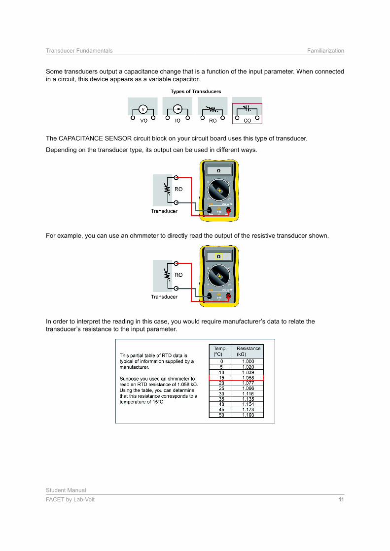
Some transducers output a capacitance change that is a function of the input parameter. When connected
in a circuit, this device appears as a variable capacitor.
The CAPACITANCE SENSOR circuit block on your circuit board uses this type of transducer.
Depending on the transducer type, its output can be used in different ways.
For example, you can use an ohmmeter to directly read the output of the resistive transducer shown.
Student Manual
12 FACET by Lab-Volt
Familiarization Transducer Fundamentals
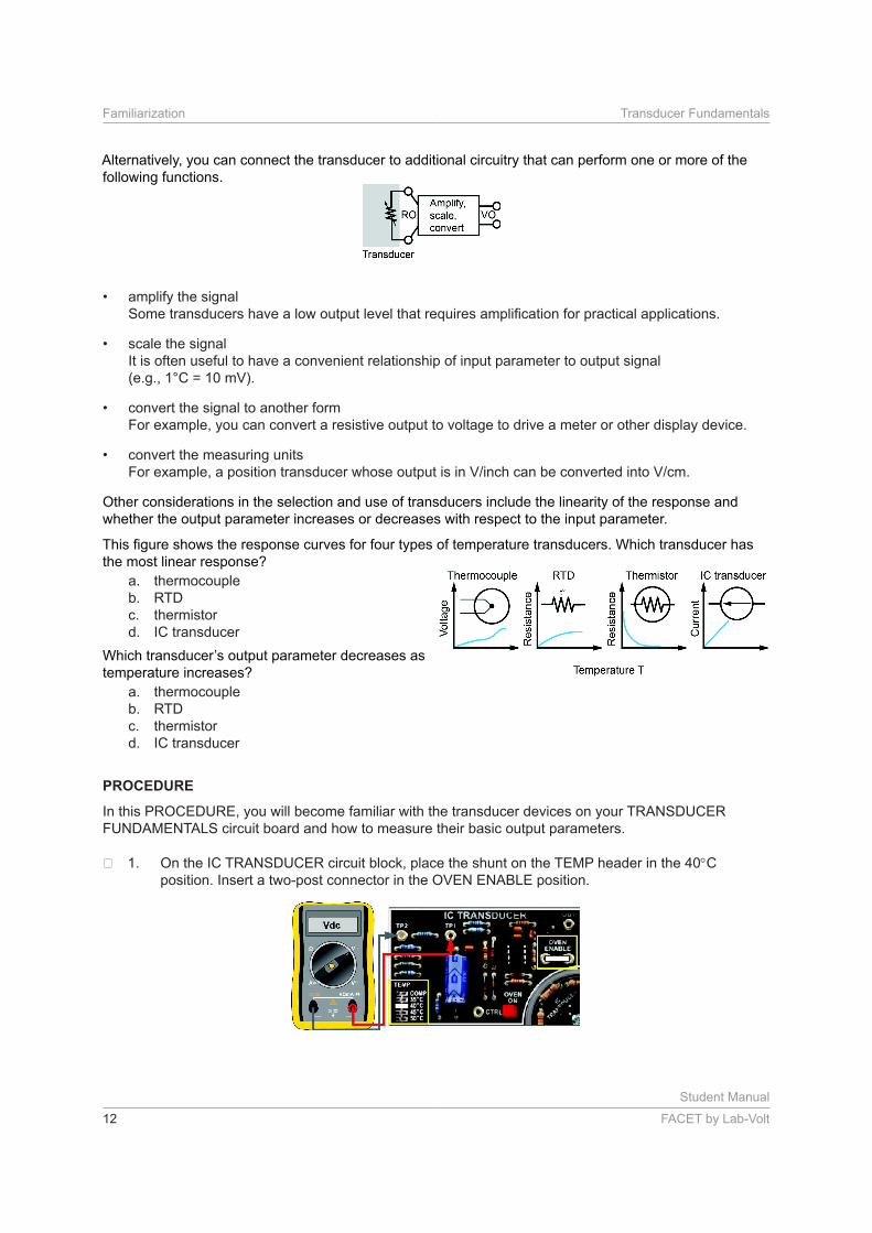
Alternatively, you can connect the transducer to additional circuitry that can perform one or more of the
following functions.
• amplify the signal
• scale the signal
It is often useful to have a convenient relationship of input parameter to output signal
(e.g., 1°C = 10 mV).
• convert the signal to another form
For example, you can convert a resistive output to voltage to drive a meter or other display device.
• convert the measuring units
Other considerations in the selection and use of transducers include the linearity of the response and
whether the output parameter increases or decreases with respect to the input parameter.
the most linear response?
a. thermocouple
b. RTD
c. thermistor
d. IC transducer
temperature increases?
a. thermocouple
b. RTD
c. thermistor
d. IC transducer
PROCEDURE
In this PROCEDURE, you will become familiar with the transducer devices on your TRANSDUCER
FUNDAMENTALS circuit board and how to measure their basic output parameters.
On the IC TRANSDUCER circuit block, place the shunt on the TEMP header in the 40 C
position. Insert a two-post connector in the OVEN ENABLE position.
Student Manual
FACET by Lab-Volt 13
Transducer Fundamentals Familiarization
These connections tell the oven controller circuitry to regulate the oven temperature at 40 C.
Since you started at room temperature (typically 25 C), the oven needs a minute or two to rise to
40 C.
Complete the following steps as you wait for the oven to reach the new temperature.
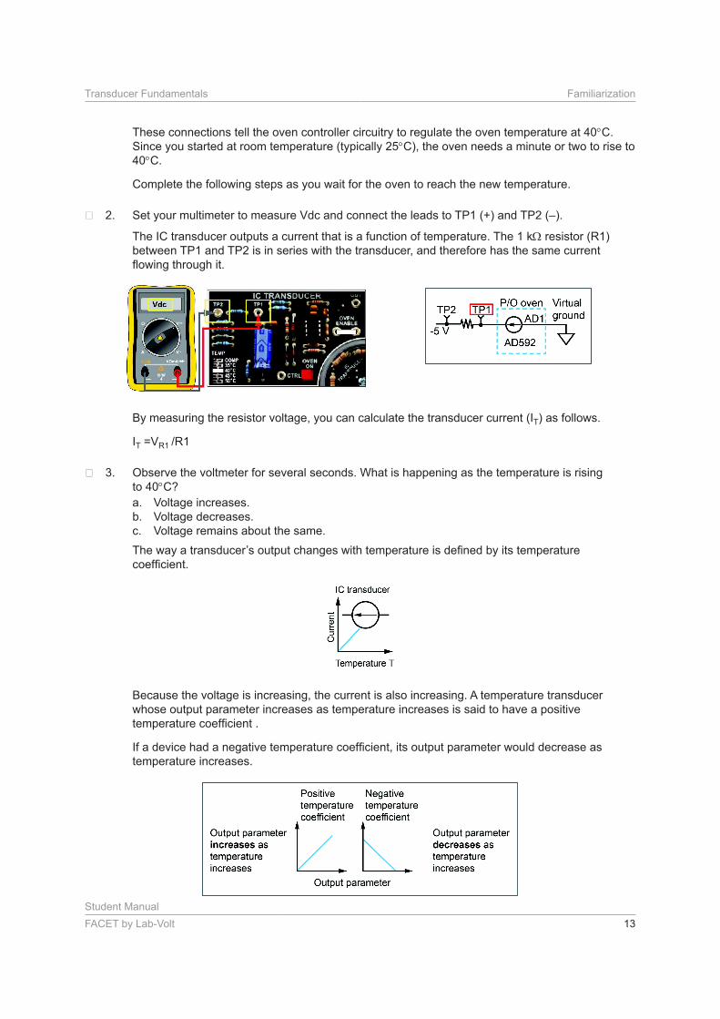
Set your multimeter to measure Vdc and connect the leads to TP1 (+) and TP2 (–).
The IC transducer outputs a current that is a function of temperature. The 1 k resistor (R1)
between TP1 and TP2 is in series with the transducer, and therefore has the same current
By measuring the resistor voltage, you can calculate the transducer current (IT) as follows.
IT =VR1
Observe the voltmeter for several seconds. What is happening as the temperature is rising
to 40 C?
a. Voltage increases.
b. Voltage decreases.
c. Voltage remains about the same.
Because the voltage is increasing, the current is also increasing. A temperature transducer
whose output parameter increases as temperature increases is said to have a positive
temperature increases.
Student Manual
14 FACET by Lab-Volt
Familiarization Transducer Fundamentals
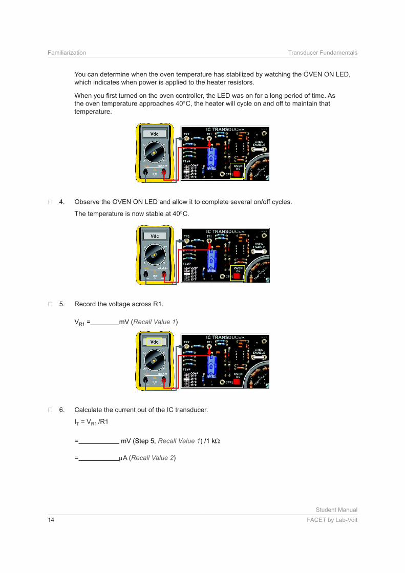
You can determine when the oven temperature has stabilized by watching the OVEN ON LED,
which indicates when power is applied to the heater resistors.
the oven temperature approaches 40 C, the heater will cycle on and off to maintain that
temperature.
The temperature is now stable at 40 C.
Record the voltage across R1.
VR1 = mV (Recall Value 1)
Calculate the current out of the IC transducer.
IT = VR1
= mV (Step 5, Recall Value 1
= A (Recall Value 2)
Student Manual
FACET by Lab-Volt 15
Transducer Fundamentals Familiarization
A. Is your
calculation of A (Step 6, Recall Value 2) close to this value?
a. yes
b. no
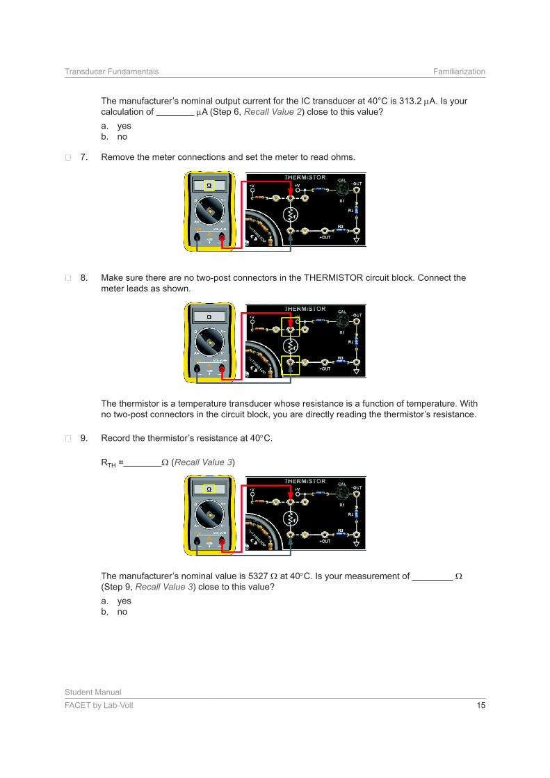
Remove the meter connections and set the meter to read ohms.
Make sure there are no two-post connectors in the THERMISTOR circuit block. Connect the
meter leads as shown.
The thermistor is a temperature transducer whose resistance is a function of temperature. With
C.
RTH = (Recall Value 3)
at 40 C. Is your measurement of
(Step 9, Recall Value 3) close to this value?
a. yes
b. no
Student Manual
16 FACET by Lab-Volt
Familiarization Transducer Fundamentals
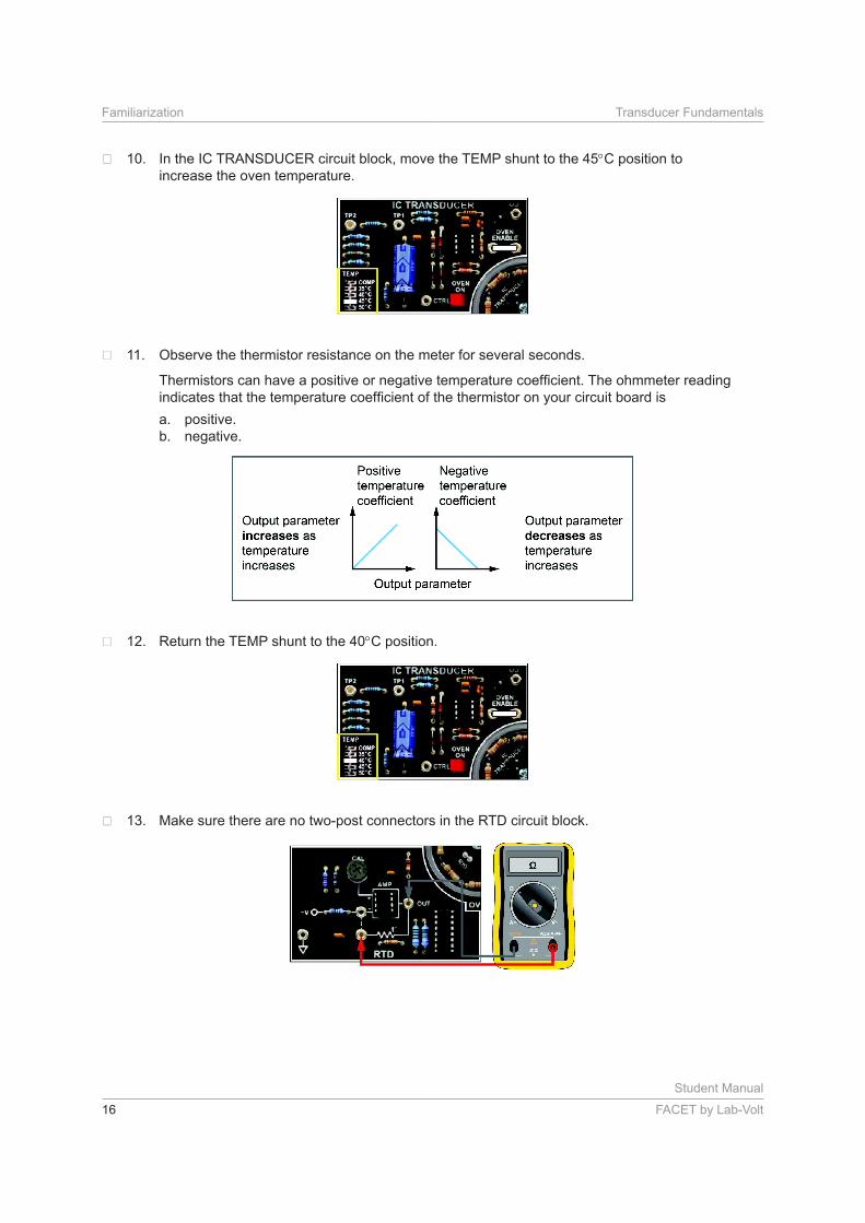
In the IC TRANSDUCER circuit block, move the TEMP shunt to the 45 C position to
increase the oven temperature.
Observe the thermistor resistance on the meter for several seconds.
a. positive.
b. negative.
Return the TEMP shunt to the 40 C position.
Make sure there are no two-post connectors in the RTD circuit block.

Student Manual
FACET by Lab-Volt 17
Transducer Fundamentals Familiarization
Remove the ohmmeter leads from the THERMISTOR circuit block and connect them across
the RTD as shown. Make sure the negative meter lead is in the OUT jack.
The RTD (resistance temperature detector) is a transducer whose resistance is a function of
temperature. What other temperature transducer has a temperature-dependent resistance
output?
a. IC transducer
b. thermistor
c. thermocouple
Observe the OVEN ON LED and allow it to complete several cycles to make sure the oven
temperature has returned to 40 C.
Record the RTD resistance at 40 C.
RRTD = (Recall Value 4)
Student Manual
18 FACET by Lab-Volt
Familiarization Transducer Fundamentals
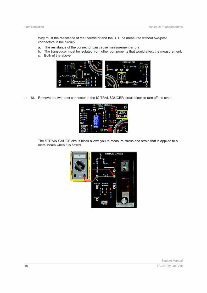
Why must the resistance of the thermistor and the RTD be measured without two-post
connectors in the circuit?
a. The resistance of the connector can cause measurement errors.
b. The transducer must be isolated from other components that would affect the measurement.
c. Both of the above
Remove the two-post connector in the IC TRANSDUCER circuit block to turn off the oven.
The STRAIN GAUGE circuit block allows you to measure stress and strain that is applied to a
Student Manual
FACET by Lab-Volt 19
Transducer Fundamentals Familiarization
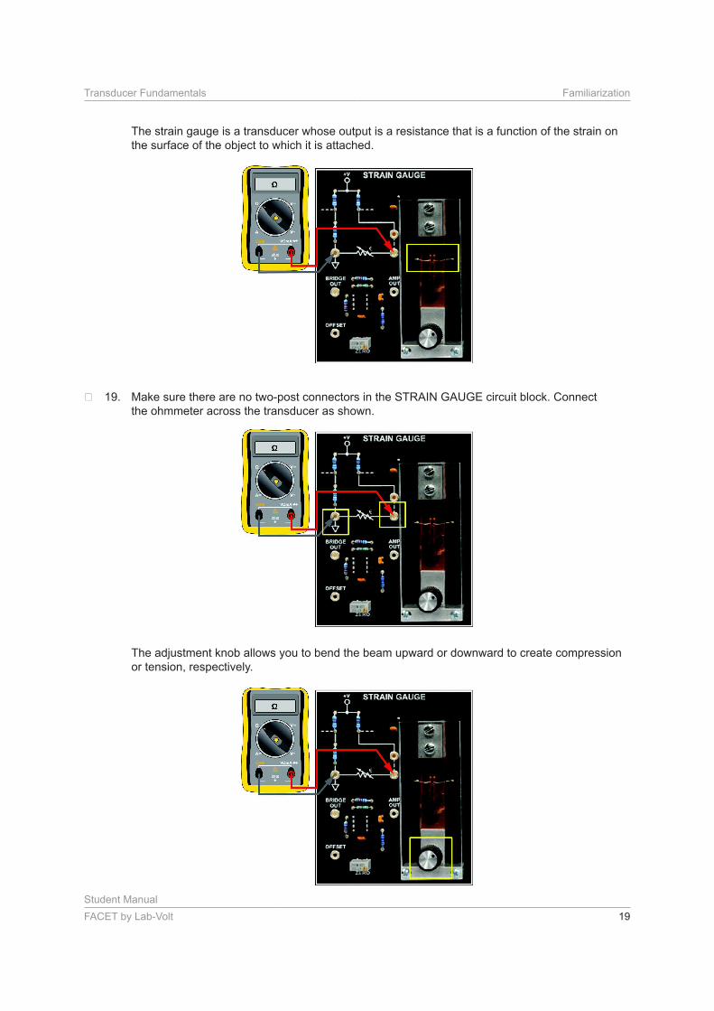
The strain gauge is a transducer whose output is a resistance that is a function of the strain on
the surface of the object to which it is attached.
Make sure there are no two-post connectors in the STRAIN GAUGE circuit block. Connect
the ohmmeter across the transducer as shown.
The adjustment knob allows you to bend the beam upward or downward to create compression
or tension, respectively.
Student Manual
20 FACET by Lab-Volt
Familiarization Transducer Fundamentals
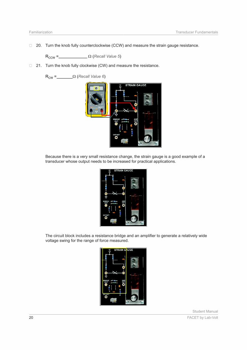
Turn the knob fully counterclockwise (CCW) and measure the strain gauge resistance.
RCCW = (Recall Value 5)
Turn the knob fully clockwise (CW) and measure the resistance.
RCW = (Recall Value 6)
Because there is a very small resistance change, the strain gauge is a good example of a
transducer whose output needs to be increased for practical applications.
voltage swing for the range of force measured.
Student Manual
FACET by Lab-Volt 21
Transducer Fundamentals Familiarization
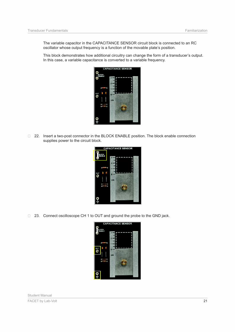
The variable capacitor in the CAPACITANCE SENSOR circuit block is connected to an RC
In this case, a variable capacitance is converted to a variable frequency.
Insert a two-post connector in the BLOCK ENABLE position. The block enable connection
supplies power to the circuit block.
Connect oscilloscope CH 1 to OUT and ground the probe to the GND jack.
Student Manual
22 FACET by Lab-Volt
Familiarization Transducer Fundamentals
Adjust the scope controls to view a square wave output from the CAPACITANCE SENSOR
circuit block.
Slide the movable plate up and down while observing the scope.
What happens to the waveform?
a. The frequency changes.
b. The amplitude changes.
c. Both of the above
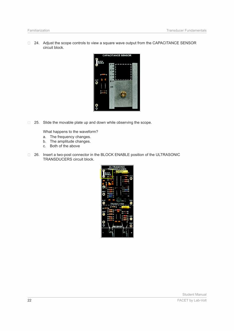
Insert a two-post connector in the BLOCK ENABLE position of the ULTRASONIC
TRANSDUCERS circuit block.
Student Manual
FACET by Lab-Volt 23
Transducer Fundamentals Familiarization
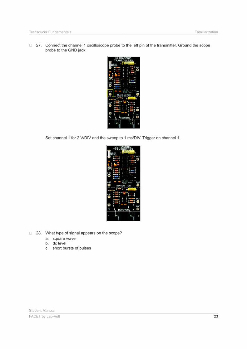
Connect the channel 1 oscilloscope probe to the left pin of the transmitter. Ground the scope
probe to the GND jack.
What type of signal appears on the scope?
a. square wave
b. dc level
c. short bursts of pulses
Student Manual
24 FACET by Lab-Volt
Familiarization Transducer Fundamentals
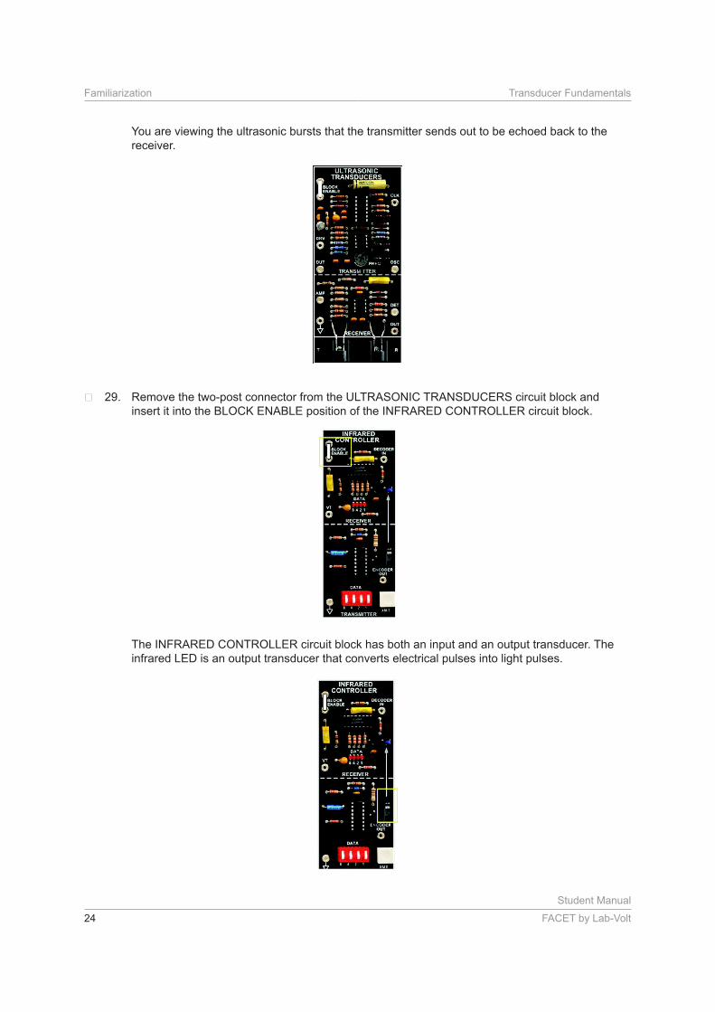
You are viewing the ultrasonic bursts that the transmitter sends out to be echoed back to the
receiver.
Remove the two-post connector from the ULTRASONIC TRANSDUCERS circuit block and
insert it into the BLOCK ENABLE position of the INFRARED CONTROLLER circuit block.
The INFRARED CONTROLLER circuit block has both an input and an output transducer. The
infrared LED is an output transducer that converts electrical pulses into light pulses.
Student Manual
FACET by Lab-Volt 25
Transducer Fundamentals Familiarization
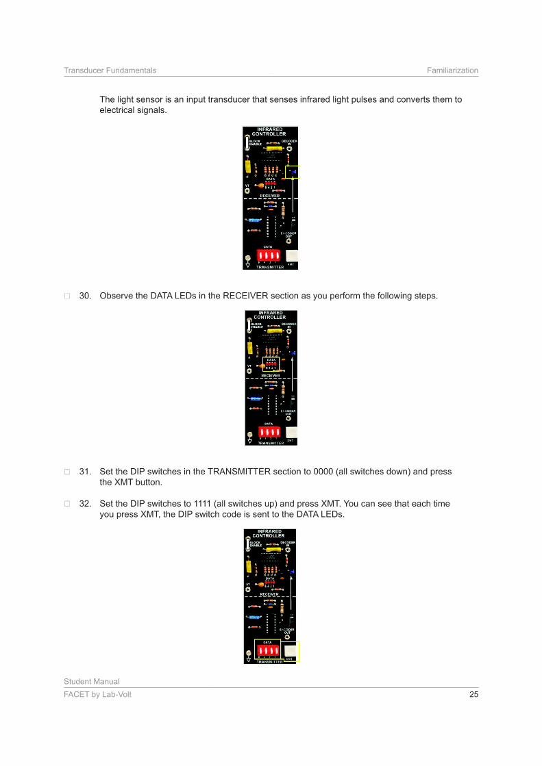
The light sensor is an input transducer that senses infrared light pulses and converts them to
electrical signals.
Observe the DATA LEDs in the RECEIVER section as you perform the following steps.
Set the DIP switches in the TRANSMITTER section to 0000 (all switches down) and press
the XMT button.
Set the DIP switches to 1111 (all switches up) and press XMT. You can see that each time
you press XMT, the DIP switch code is sent to the DATA LEDs.
Student Manual
26 FACET by Lab-Volt
Familiarization Transducer Fundamentals
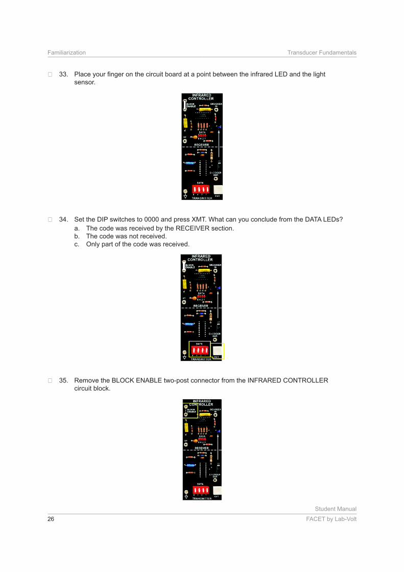
sensor.
Set the DIP switches to 0000 and press XMT. What can you conclude from the DATA LEDs?
a. The code was received by the RECEIVER section.
b. The code was not received.
c. Only part of the code was received.
Remove the BLOCK ENABLE two-post connector from the INFRARED CONTROLLER
circuit block.
Student Manual
FACET by Lab-Volt 27
Transducer Fundamentals Familiarization
CONCLUSION
• Input transducers (sensors) convert a physical quantity into a proportional electrical signal.
• Output transducers convert an electrical signal into a physical quantity that can be detected or used
externally.
•
• Transducers often require additional circuitry to amplify the output or to convert the output parameter
to another form.
REVIEW QUESTIONS
1. A transducer converts
a. temperature to resistance.
b. force into current.
c. position into voltage.
d. one form of energy to another.
2. Which circuit block on the TRANSDUCER FUNDAMENTALS circuit board shows a schematic symbol
of a transducer whose output is a change in resistance?
a. THERMISTOR
b. RTD
c. STRAIN GAUGE
d. All of the above
3. Which device on the TRANSDUCER FUNDAMENTALS circuit board is an output transducer?
a. strain gauge
b. infrared LED
c. RTD
d. thermistor
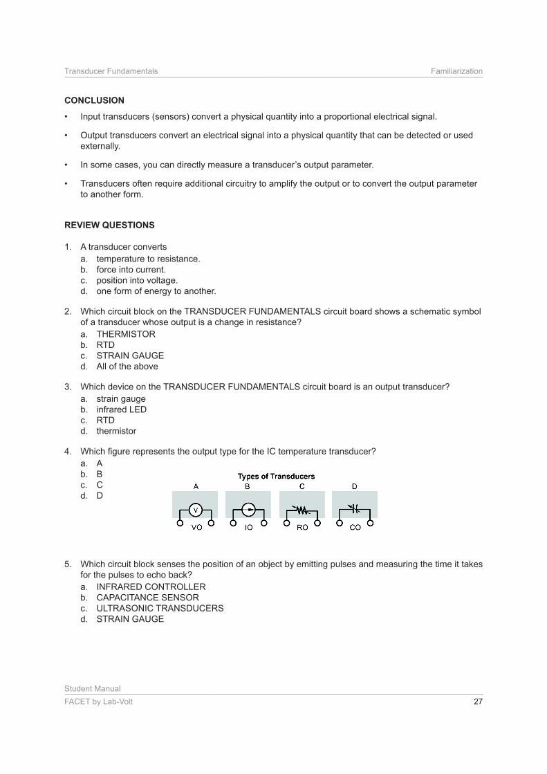
4.
a. A
b. B
c. C
d. D
5. Which circuit block senses the position of an object by emitting pulses and measuring the time it takes
for the pulses to echo back?
a. INFRARED CONTROLLER
b. CAPACITANCE SENSOR
c. ULTRASONIC TRANSDUCERS
d. STRAIN GAUGE