exercise 2: ir remote control - lab-volt manual 334 facet by lab-volt the infrared controller...
TRANSCRIPT
Student Manual
334 FACET by Lab-Volt
The Infrared Controller Transducer Fundamentals
Exercise 2: IR Remote Control
EXERCISE OBJECTIVE
When you have completed this exercise, you will be able to describe how digital data is transferred via
infrared light, demonstrate typical data encoding and decoding techniques used in IR remote control
applications, and explain how infrared light can be used to remotely control electronic equipment. You will
use an oscilloscope to make observations and measurements.
DISCUSSION
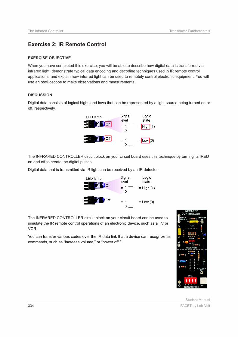
Digital data consists of logical highs and lows that can be represented by a light source being turned on or
off, respectively.
The INFRARED CONTROLLER circuit block on your circuit board uses this technique by turning its IRED
on and off to create the digital pulses.
Digital data that is transmitted via IR light can be received by an IR detector.
The INFRARED CONTROLLER circuit block on your circuit board can be used to
simulate the IR remote control operations of an electronic device, such as a TV or
VCR.
You can transfer various codes over the IR data link that a device can recognize as
commands, such as “increase volume,” or “power off.”
Student Manual
FACET by Lab-Volt 335
Transducer Fundamentals The Infrared Controller
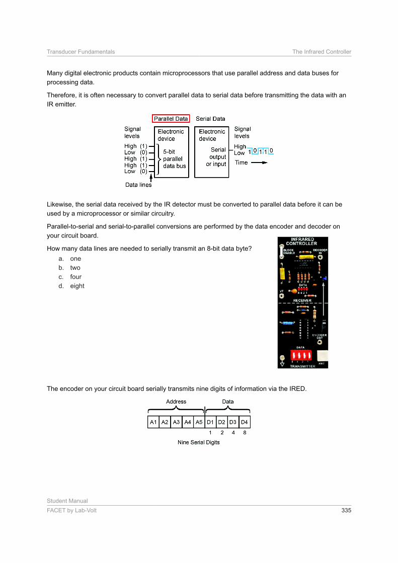
Many digital electronic products contain microprocessors that use parallel address and data buses for
processing data.
Therefore, it is often necessary to convert parallel data to serial data before transmitting the data with an
IR emitter.
Likewise, the serial data received by the IR detector must be converted to parallel data before it can be
used by a microprocessor or similar circuitry.
Parallel-to-serial and serial-to-parallel conversions are performed by the data encoder and decoder on
your circuit board.
How many data lines are needed to serially transmit an 8-bit data byte?
a. one
b. two
c. four
d. eight
The encoder on your circuit board serially transmits nine digits of information via the IRED.
Student Manual
336 FACET by Lab-Volt
The Infrared Controller Transducer Fundamentals
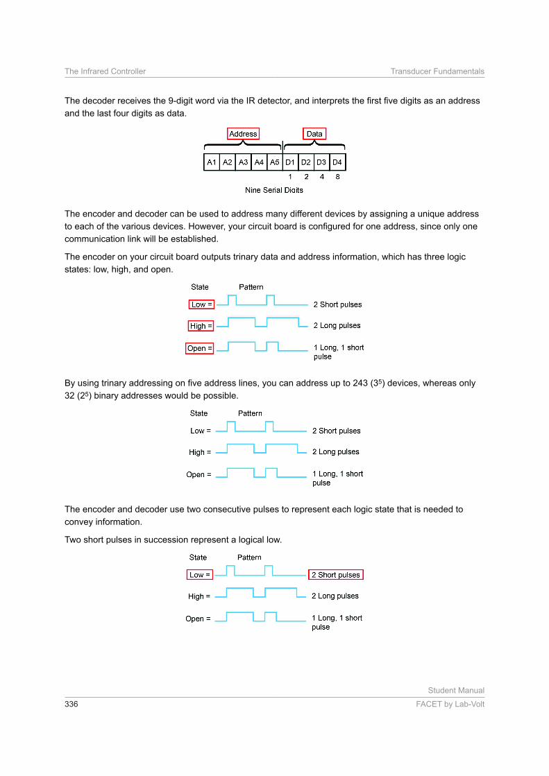
and the last four digits as data.
The encoder and decoder can be used to address many different devices by assigning a unique address
communication link will be established.
The encoder on your circuit board outputs trinary data and address information, which has three logic
states: low, high, and open.
5) devices, whereas only
32 (25) binary addresses would be possible.
The encoder and decoder use two consecutive pulses to represent each logic state that is needed to
convey information.
Two short pulses in succession represent a logical low.
Student Manual
FACET by Lab-Volt 337
Transducer Fundamentals The Infrared Controller
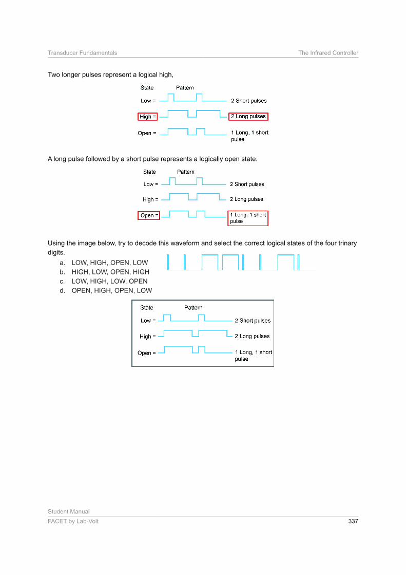
Two longer pulses represent a logical high,
A long pulse followed by a short pulse represents a logically open state.
Using the image below, try to decode this waveform and select the correct logical states of the four trinary
digits.
a. LOW, HIGH, OPEN, LOW
b. HIGH, LOW, OPEN, HIGH
c. LOW, HIGH, LOW, OPEN
d. OPEN, HIGH, OPEN, LOW
Student Manual
338 FACET by Lab-Volt
The Infrared Controller Transducer Fundamentals
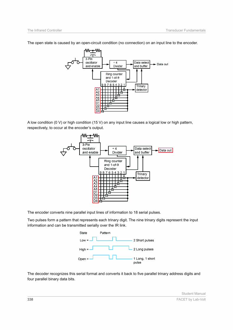
The open state is caused by an open-circuit condition (no connection) on an input line to the encoder.
A low condition (0 V) or high condition (15 V) on any input line causes a logical low or high pattern,
The encoder converts nine parallel input lines of information to 18 serial pulses.
Two pulses form a pattern that represents each trinary digit. The nine trinary digits represent the input
information and can be transmitted serially over the IR link.
four parallel binary data bits.
Student Manual
FACET by Lab-Volt 339
Transducer Fundamentals The Infrared Controller
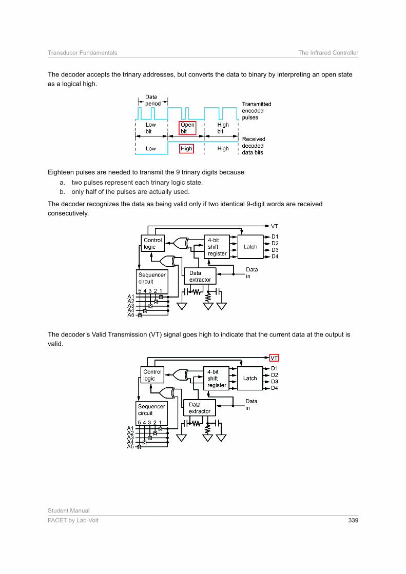
The decoder accepts the trinary addresses, but converts the data to binary by interpreting an open state
as a logical high.
Eighteen pulses are needed to transmit the 9 trinary digits because
a. two pulses represent each trinary logic state.
b. only half of the pulses are actually used.
The decoder recognizes the data as being valid only if two identical 9-digit words are received
consecutively.
valid.
Student Manual
340 FACET by Lab-Volt
The Infrared Controller Transducer Fundamentals
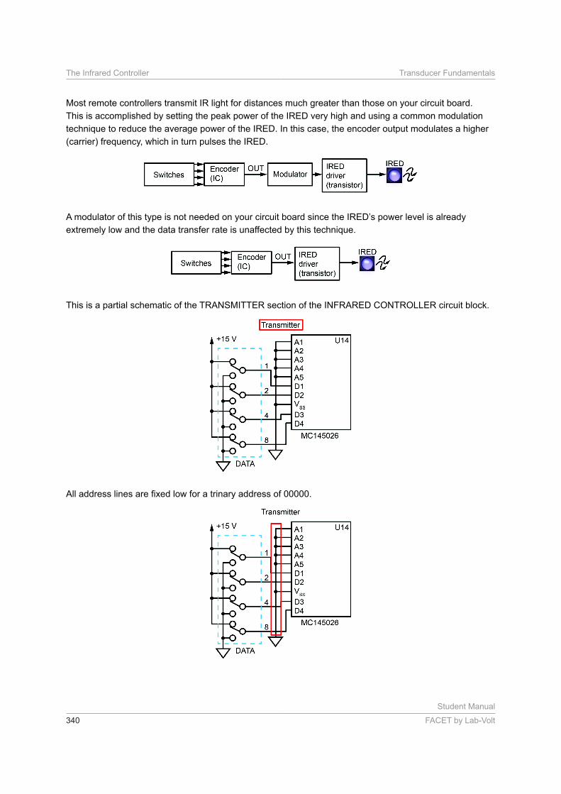
Most remote controllers transmit IR light for distances much greater than those on your circuit board.
This is accomplished by setting the peak power of the IRED very high and using a common modulation
technique to reduce the average power of the IRED. In this case, the encoder output modulates a higher
(carrier) frequency, which in turn pulses the IRED.
extremely low and the data transfer rate is unaffected by this technique.
This is a partial schematic of the TRANSMITTER section of the INFRARED CONTROLLER circuit block.
Student Manual
FACET by Lab-Volt 341
Transducer Fundamentals The Infrared Controller
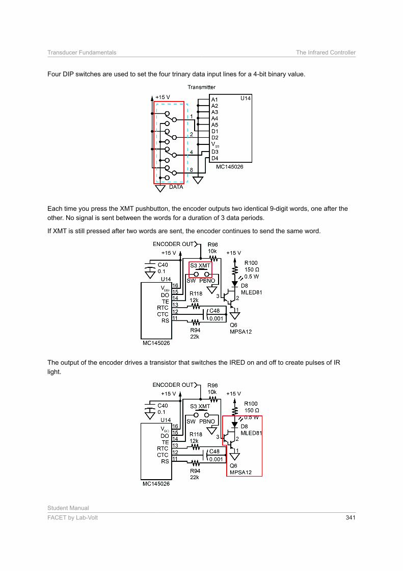
Four DIP switches are used to set the four trinary data input lines for a 4-bit binary value.
Each time you press the XMT pushbutton, the encoder outputs two identical 9-digit words, one after the
other. No signal is sent between the words for a duration of 3 data periods.
If XMT is still pressed after two words are sent, the encoder continues to send the same word.
The output of the encoder drives a transistor that switches the IRED on and off to create pulses of IR
light.

Student Manual
342 FACET by Lab-Volt
The Infrared Controller Transducer Fundamentals
If you hold down the XMT button on your circuit board, the encoder will continue to send
a.
b. spaces after two words are sent.
c. two sets of identical words.
This is a schematic of the RECEIVER section of the INFRARED CONTROLLER circuit block.
Student Manual
FACET by Lab-Volt 343
Transducer Fundamentals The Infrared Controller
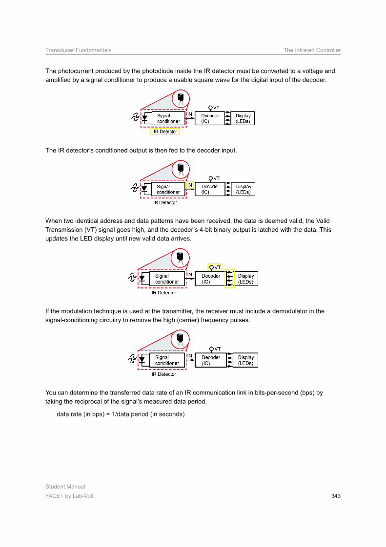
The photocurrent produced by the photodiode inside the IR detector must be converted to a voltage and
When two identical address and data patterns have been received, the data is deemed valid, the Valid
updates the LED display until new valid data arrives.
If the modulation technique is used at the transmitter, the receiver must include a demodulator in the
signal-conditioning circuitry to remove the high (carrier) frequency pulses.
You can determine the transferred data rate of an IR communication link in bits-per-second (bps) by
Student Manual
344 FACET by Lab-Volt
The Infrared Controller Transducer Fundamentals
Digital instruction codes are commonly sent via IR light to a device to perform a task or to provide a
For example, a TV may have several different codes to control the power, set the volume, and change the
channels.
off the TV set.
PROCEDURE
In this PROCEDURE, you will make observations and measurements on IR remote control circuitry by
using your oscilloscope.
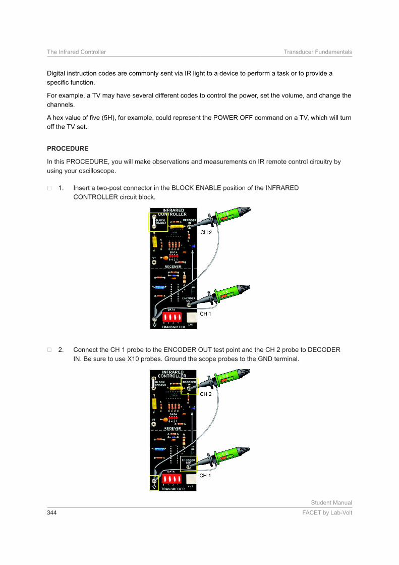
Insert a two-post connector in the BLOCK ENABLE position of the INFRARED
CONTROLLER circuit block.
Connect the CH 1 probe to the ENCODER OUT test point and the CH 2 probe to DECODER
IN. Be sure to use X10 probes. Ground the scope probes to the GND terminal.
Student Manual
FACET by Lab-Volt 345
Transducer Fundamentals The Infrared Controller
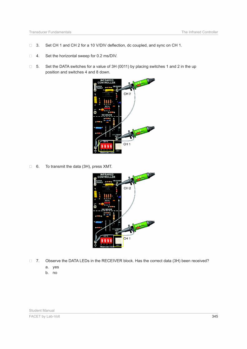
Set the DATA switches for a value of 3H (0011) by placing switches 1 and 2 in the up
position and switches 4 and 8 down.
To transmit the data (3H), press XMT.
Observe the DATA LEDs in the RECEIVER block. Has the correct data (3H) been received?
a. yes
b. no
Student Manual
346 FACET by Lab-Volt
The Infrared Controller Transducer Fundamentals
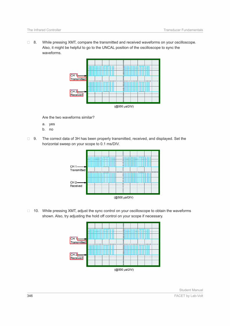
While pressing XMT, compare the transmitted and received waveforms on your oscilloscope.
Also, it might be helpful to go to the UNCAL position of the oscilloscope to sync the
waveforms.
Are the two waveforms similar?
a. yes
b. no
The correct data of 3H has been properly transmitted, received, and displayed. Set the
While pressing XMT, adjust the sync control on your oscilloscope to obtain the waveforms
shown. Also, try adjusting the hold off control on your scope if necessary.
Student Manual
FACET by Lab-Volt 347
Transducer Fundamentals The Infrared Controller
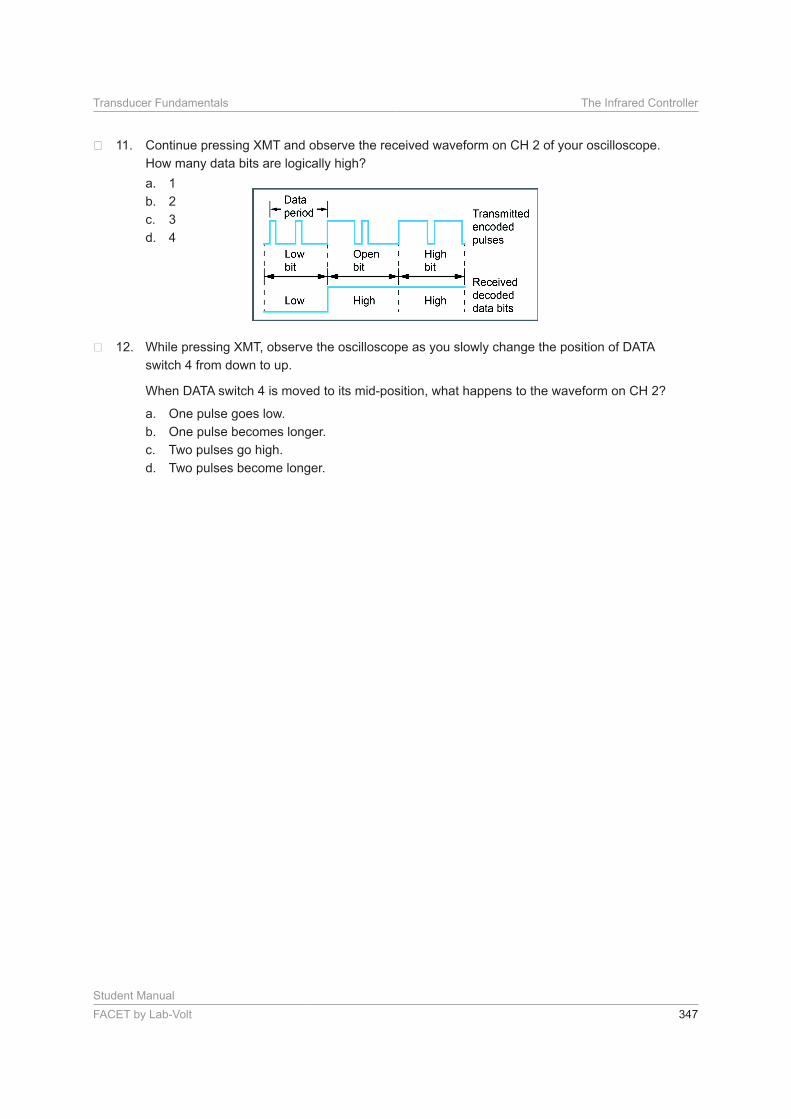
Continue pressing XMT and observe the received waveform on CH 2 of your oscilloscope.
How many data bits are logically high?
a. 1
b. 2
c. 3
d. 4
While pressing XMT, observe the oscilloscope as you slowly change the position of DATA
switch 4 from down to up.
When DATA switch 4 is moved to its mid-position, what happens to the waveform on CH 2?
a. One pulse goes low.
b. One pulse becomes longer.
c. Two pulses go high.
d. Two pulses become longer.
Student Manual
348 FACET by Lab-Volt
The Infrared Controller Transducer Fundamentals
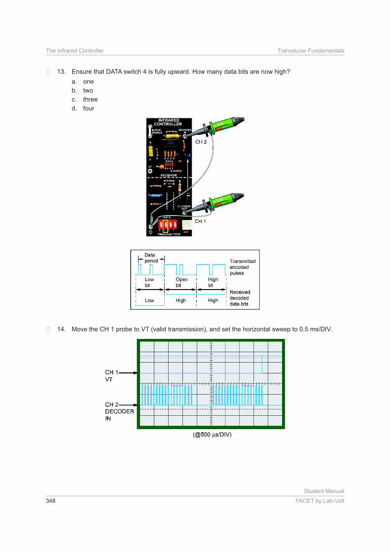
Ensure that DATA switch 4 is fully upward. How many data bits are now high?
a. one
b. two
c. three
d. four

Student Manual
FACET by Lab-Volt 349
Transducer Fundamentals The Infrared Controller
Set the vertical mode to CHOP and the trigger mode to NORMAL. Trigger the scope on
CH 2, with a positive slope.
While pressing XMT, adjust the sync control on your scope for the waveforms shown.
NOTE: The low pulse on CH 1 appears only at the instant you press XMT.
Press XMT several times as you observe the waveform (VT) on CH 1.
NOTE: If your oscilloscope has a single-sweep trigger mode, use it to perform this step.
With each depression of XMT, is the waveform on CH 1 similar to the one shown?
a. yes
b. no
Place all DATA switches down, for 0H.
Set the horizontal sweep on your oscilloscope to 50
Student Manual
350 FACET by Lab-Volt
The Infrared Controller Transducer Fundamentals
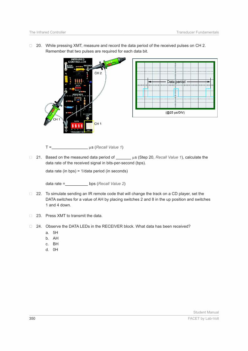
While pressing XMT, measure and record the data period of the received pulses on CH 2.
Remember that two pulses are required for each data bit.
T = s (Recall Value 1)
Based on the measured data period of s (Step 20, Recall Value 1), calculate the
data rate of the received signal in bits-per-second (bps).
data rate = bps (Recall Value 2)
To simulate sending an IR remote code that will change the track on a CD player, set the
DATA switches for a value of AH by placing switches 2 and 8 in the up position and switches
1 and 4 down.
Press XMT to transmit the data.
Observe the DATA LEDs in the RECEIVER block. What data has been received?
a. 5H
b. AH
c. BH
d. 0H
Student Manual
FACET by Lab-Volt 351
Transducer Fundamentals The Infrared Controller
CONCLUSION
• Digital data is transferred serially over an IR link.
• Parallel-to-serial and serial-to-parallel conversions are often required by controller circuitry.
• Encoding and decoding techniques are used to exchange information, such as device address and
control data.
• Numerous instruction codes can be sent over an IR link to remotely select different functions and
perform various tasks.
• Many different address codes can be sent over an IR link to remotely select and control several
devices.
• Trinary addressing provides a wider address range than binary for the same amount of address lines.
REVIEW QUESTIONS
1. To convert trinary data to binary, the decoder on your circuit board interprets logical
a. lows as highs.
b. highs as lows.
c. opens as highs.
d. opens as lows.
2. What conversion must the encoder perform before it can transmit the data that is set by the four DATA
switches on your circuit board?
a. serial-to-parallel
b. parallel-to-serial
c. binary-to-trinary
d. trinary-to-binary
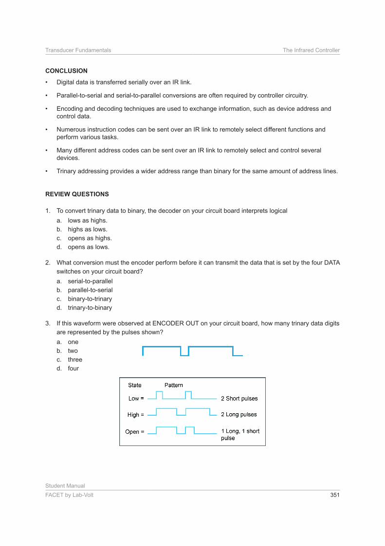
3. If this waveform were observed at ENCODER OUT on your circuit board, how many trinary data digits
are represented by the pulses shown?
a. one
b. two
c. three
d. four
Student Manual
352 FACET by Lab-Volt
The Infrared Controller Transducer Fundamentals
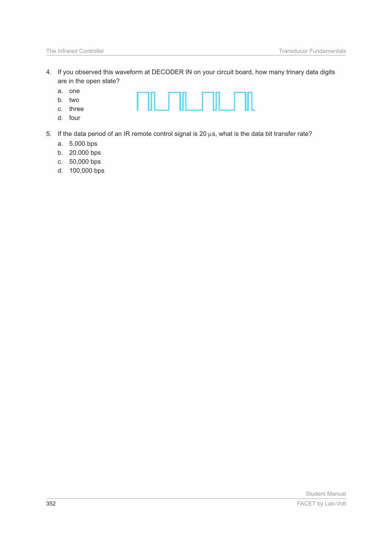
4. If you observed this waveform at DECODER IN on your circuit board, how many trinary data digits
are in the open state?
a. one
b. two
c. three
d. four
5. If the data period of an IR remote control signal is 20 s, what is the data bit transfer rate?
a. 5,000 bps
b. 20,000 bps
c. 50,000 bps
d. 100,000 bps