automation and robotics, robot system, series 5150 - lab-volt
TRANSCRIPT
(732) 938-2000 / 800-LAB-VOLT, FAX: (732) 774-8573, E-MAIL: [email protected](418) 849-1000 / 800-LAB-VOLT, FAX: (418) 849-1666, E-MAIL: [email protected]
INTERNET: http://www.labvolt.com
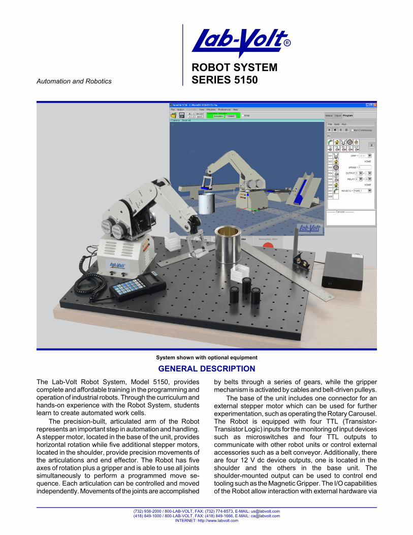
System shown with optional equipment
AAutomation and Robotics
ROBOT SYSTEMSERIES 5150
GENERAL DESCRIPTION
The Lab-Volt Robot System, Model 5150, providescomplete and affordable training in the programming andoperation of industrial robots. Through the curriculum andhands-on experience with the Robot System, studentslearn to create automated work cells.
The precision-built, articulated arm of the Robotrepresents an important step in automation and handling.A stepper motor, located in the base of the unit, provideshorizontal rotation while five additional stepper motors,located in the shoulder, provide precision movements ofthe articulations and end effector. The Robot has fiveaxes of rotation plus a gripper and is able to use all jointssimultaneously to perform a programmed move se-quence. Each articulation can be controlled and movedindependently. Movements of the joints are accomplished
by belts through a series of gears, while the grippermechanism is activated by cables and belt-driven pulleys.
The base of the unit includes one connector for anexternal stepper motor which can be used for furtherexperimentation, such as operating the Rotary Carousel.The Robot is equipped with four TTL (Transistor-Transistor Logic) inputs for the monitoring of input devicessuch as microswitches and four TTL outputs tocommunicate with other robot units or control externalaccessories such as a belt conveyor. Additionally, thereare four 12 V dc device outputs, one is located in theshoulder and the others in the base unit. Theshoulder-mounted output can be used to control endtooling such as the Magnetic Gripper. The I/O capabilitiesof the Robot allow interaction with external hardware via
ROBOT SYSTEMSERIES 5150
2
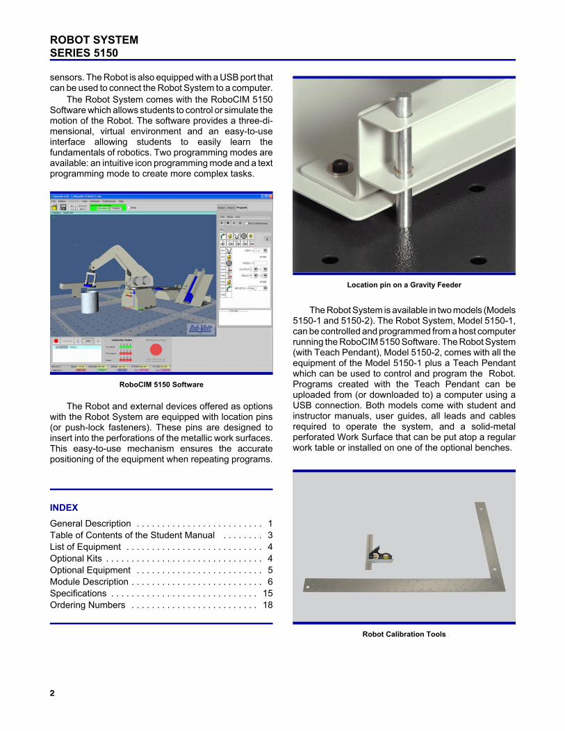
RoboCIM 5150 Software
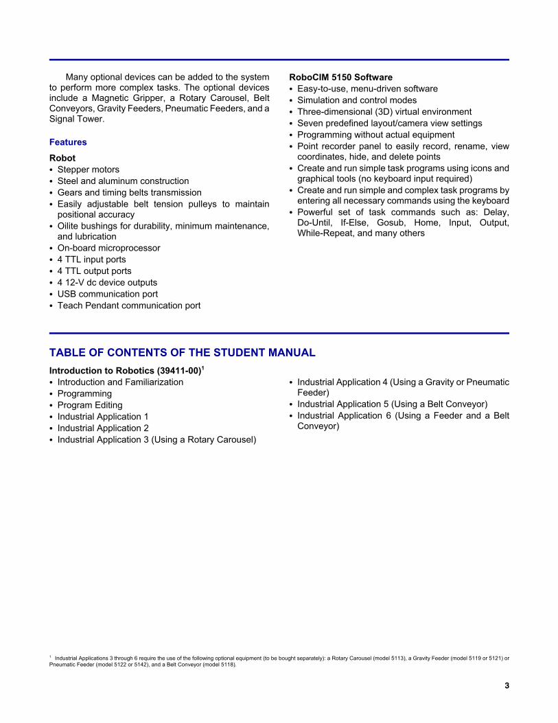
Location pin on a Gravity Feeder
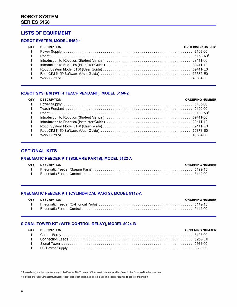
Robot Calibration Tools
sensors. The Robot is also equipped with a USB port thatcan be used to connect the Robot System to a computer.
The Robot System comes with the RoboCIM 5150Software which allows students to control or simulate themotion of the Robot. The software provides a three-di-mensional, virtual environment and an easy-to-useinterface allowing students to easily learn thefundamentals of robotics. Two programming modes areavailable: an intuitive icon programming mode and a textprogramming mode to create more complex tasks.
The Robot and external devices offered as optionswith the Robot System are equipped with location pins(or push-lock fasteners). These pins are designed toinsert into the perforations of the metallic work surfaces.This easy-to-use mechanism ensures the accuratepositioning of the equipment when repeating programs.
INDEX
General Description . . . . . . . . . . . . . . . . . . . . . . . . . 1Table of Contents of the Student Manual . . . . . . . . 3List of Equipment . . . . . . . . . . . . . . . . . . . . . . . . . . . 4Optional Kits . . . . . . . . . . . . . . . . . . . . . . . . . . . . . . . 4Optional Equipment . . . . . . . . . . . . . . . . . . . . . . . . . 5Module Description . . . . . . . . . . . . . . . . . . . . . . . . . . 6Specifications . . . . . . . . . . . . . . . . . . . . . . . . . . . . . 15Ordering Numbers . . . . . . . . . . . . . . . . . . . . . . . . . 18
The Robot System is available in two models (Models5150-1 and 5150-2). The Robot System, Model 5150-1,can be controlled and programmed from a host computerrunning the RoboCIM 5150 Software. The Robot System(with Teach Pendant), Model 5150-2, comes with all theequipment of the Model 5150-1 plus a Teach Pendantwhich can be used to control and program the Robot.Programs created with the Teach Pendant can beuploaded from (or downloaded to) a computer using aUSB connection. Both models come with student andinstructor manuals, user guides, all leads and cablesrequired to operate the system, and a solid-metalperforated Work Surface that can be put atop a regularwork table or installed on one of the optional benches.
1 Industrial Applications 3 through 6 require the use of the following optional equipment (to be bought separately): a Rotary Carousel (model 5113), a Gravity Feeder (model 5119 or 5121) orPneumatic Feeder (model 5122 or 5142), and a Belt Conveyor (model 5118).
3
Many optional devices can be added to the systemto perform more complex tasks. The optional devicesinclude a Magnetic Gripper, a Rotary Carousel, BeltConveyors, Gravity Feeders, Pneumatic Feeders, and aSignal Tower.
Features
RobotC Stepper motorsC Steel and aluminum constructionC Gears and timing belts transmissionC Easily adjustable belt tension pulleys to maintain
positional accuracyC Oilite bushings for durability, minimum maintenance,
and lubricationC On-board microprocessorC 4 TTL input portsC 4 TTL output portsC 4 12-V dc device outputsC USB communication portC Teach Pendant communication port
RoboCIM 5150 SoftwareC Easy-to-use, menu-driven softwareC Simulation and control modesC Three-dimensional (3D) virtual environmentC Seven predefined layout/camera view settingsC Programming without actual equipmentC Point recorder panel to easily record, rename, view
coordinates, hide, and delete pointsC Create and run simple task programs using icons and
graphical tools (no keyboard input required)C Create and run simple and complex task programs by
entering all necessary commands using the keyboardC Powerful set of task commands such as: Delay,
Do-Until, If-Else, Gosub, Home, Input, Output,While-Repeat, and many others
TABLE OF CONTENTS OF THE STUDENT MANUAL
Introduction to Robotics (39411-00)1
C Introduction and FamiliarizationC ProgrammingC Program EditingC Industrial Application 1C Industrial Application 2C Industrial Application 3 (Using a Rotary Carousel)
C Industrial Application 4 (Using a Gravity or PneumaticFeeder)
C Industrial Application 5 (Using a Belt Conveyor)C Industrial Application 6 (Using a Feeder and a Belt
Conveyor)
ROBOT SYSTEMSERIES 5150
2 The ordering numbers shown apply to the English 120-V version. Other versions are available. Refer to the Ordering Numbers section.
3 Includes the RoboCIM 5150 Software, Robot calibration tools, and all the leads and cables required to operate the system.
4
LISTS OF EQUIPMENT
ROBOT SYSTEM, MODEL 5150-1
QTY DESCRIPTION ORDERING NUMBER2
1 Power Supply . . . . . . . . . . . . . . . . . . . . . . . . . . . . . . . . . . . . . . . . . . . . . . . . . . . . . . . . . . . . . . . . . . 5105-001 Robot . . . . . . . . . . . . . . . . . . . . . . . . . . . . . . . . . . . . . . . . . . . . . . . . . . . . . . . . . . . . . . . . . . . . . . . . 5150-A03
1 Introduction to Robotics (Student Manual) . . . . . . . . . . . . . . . . . . . . . . . . . . . . . . . . . . . . . . . . . . . 39411-001 Introduction to Robotics (Instructor Guide) . . . . . . . . . . . . . . . . . . . . . . . . . . . . . . . . . . . . . . . . . . . 39411-101 Robot System Model 5150 (User Guide) . . . . . . . . . . . . . . . . . . . . . . . . . . . . . . . . . . . . . . . . . . . . . 39411-E01 RoboCIM 5150 Software (User Guide) . . . . . . . . . . . . . . . . . . . . . . . . . . . . . . . . . . . . . . . . . . . . . . 39376-E01 Work Surface . . . . . . . . . . . . . . . . . . . . . . . . . . . . . . . . . . . . . . . . . . . . . . . . . . . . . . . . . . . . . . . . . 46604-00
ROBOT SYSTEM (WITH TEACH PENDANT), MODEL 5150-2
QTY DESCRIPTION ORDERING NUMBER
1 Power Supply . . . . . . . . . . . . . . . . . . . . . . . . . . . . . . . . . . . . . . . . . . . . . . . . . . . . . . . . . . . . . . . . . . 5105-001 Teach Pendant . . . . . . . . . . . . . . . . . . . . . . . . . . . . . . . . . . . . . . . . . . . . . . . . . . . . . . . . . . . . . . . . . 5106-001 Robot . . . . . . . . . . . . . . . . . . . . . . . . . . . . . . . . . . . . . . . . . . . . . . . . . . . . . . . . . . . . . . . . . . . . . . . . 5150-A03
1 Introduction to Robotics (Student Manual) . . . . . . . . . . . . . . . . . . . . . . . . . . . . . . . . . . . . . . . . . . . 39411-001 Introduction to Robotics (Instructor Guide) . . . . . . . . . . . . . . . . . . . . . . . . . . . . . . . . . . . . . . . . . . . 39411-101 Robot System Model 5150 (User Guide) . . . . . . . . . . . . . . . . . . . . . . . . . . . . . . . . . . . . . . . . . . . . . 39411-E01 RoboCIM 5150 Software (User Guide) . . . . . . . . . . . . . . . . . . . . . . . . . . . . . . . . . . . . . . . . . . . . . . 39376-E01 Work Surface . . . . . . . . . . . . . . . . . . . . . . . . . . . . . . . . . . . . . . . . . . . . . . . . . . . . . . . . . . . . . . . . . 46604-00
OPTIONAL KITS
PNEUMATIC FEEDER KIT (SQUARE PARTS), MODEL 5122-A
QTY DESCRIPTION ORDERING NUMBER
1 Pneumatic Feeder (Square Parts) . . . . . . . . . . . . . . . . . . . . . . . . . . . . . . . . . . . . . . . . . . . . . . . . . . . 5122-101 Pneumatic Feeder Controller . . . . . . . . . . . . . . . . . . . . . . . . . . . . . . . . . . . . . . . . . . . . . . . . . . . . . . 5149-00
PNEUMATIC FEEDER KIT (CYLINDRICAL PARTS), MODEL 5142-A
QTY DESCRIPTION ORDERING NUMBER
1 Pneumatic Feeder (Cylindrical Parts) . . . . . . . . . . . . . . . . . . . . . . . . . . . . . . . . . . . . . . . . . . . . . . . . 5142-101 Pneumatic Feeder Controller . . . . . . . . . . . . . . . . . . . . . . . . . . . . . . . . . . . . . . . . . . . . . . . . . . . . . . 5149-00
SIGNAL TOWER KIT (WITH CONTROL RELAY), MODEL 5924-B
QTY DESCRIPTION ORDERING NUMBER
1 Control Relay . . . . . . . . . . . . . . . . . . . . . . . . . . . . . . . . . . . . . . . . . . . . . . . . . . . . . . . . . . . . . . . . . . 5125-001 Connection Leads . . . . . . . . . . . . . . . . . . . . . . . . . . . . . . . . . . . . . . . . . . . . . . . . . . . . . . . . . . . . . . . 5259-C01 Signal Tower . . . . . . . . . . . . . . . . . . . . . . . . . . . . . . . . . . . . . . . . . . . . . . . . . . . . . . . . . . . . . . . . . . . 5924-001 DC Power Supply . . . . . . . . . . . . . . . . . . . . . . . . . . . . . . . . . . . . . . . . . . . . . . . . . . . . . . . . . . . . . . . 6360-00
4 The Acoustic Alarm must be installed on a fully functional Signal Tower.
5 The Work Surfaces are not included with the Bench.
5
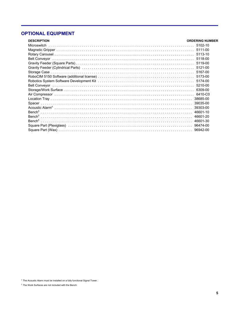
OPTIONAL EQUIPMENT
DESCRIPTION ORDERING NUMBER
Microswitch . . . . . . . . . . . . . . . . . . . . . . . . . . . . . . . . . . . . . . . . . . . . . . . . . . . . . . . . . . . . . . . . . . . . . . . . . . 5102-10Magnetic Gripper . . . . . . . . . . . . . . . . . . . . . . . . . . . . . . . . . . . . . . . . . . . . . . . . . . . . . . . . . . . . . . . . . . . . . . 5111-00Rotary Carousel . . . . . . . . . . . . . . . . . . . . . . . . . . . . . . . . . . . . . . . . . . . . . . . . . . . . . . . . . . . . . . . . . . . . . . . 5113-10Belt Conveyor . . . . . . . . . . . . . . . . . . . . . . . . . . . . . . . . . . . . . . . . . . . . . . . . . . . . . . . . . . . . . . . . . . . . . . . . 5118-00Gravity Feeder (Square Parts) . . . . . . . . . . . . . . . . . . . . . . . . . . . . . . . . . . . . . . . . . . . . . . . . . . . . . . . . . . . . 5119-00Gravity Feeder (Cylindrical Parts) . . . . . . . . . . . . . . . . . . . . . . . . . . . . . . . . . . . . . . . . . . . . . . . . . . . . . . . . . 5121-00Storage Case . . . . . . . . . . . . . . . . . . . . . . . . . . . . . . . . . . . . . . . . . . . . . . . . . . . . . . . . . . . . . . . . . . . . . . . . . 5167-00RoboCIM 5150 Software (additional license) . . . . . . . . . . . . . . . . . . . . . . . . . . . . . . . . . . . . . . . . . . . . . . . . . 5173-00Robotics System Software Development Kit . . . . . . . . . . . . . . . . . . . . . . . . . . . . . . . . . . . . . . . . . . . . . . . . . 5174-00Belt Conveyor . . . . . . . . . . . . . . . . . . . . . . . . . . . . . . . . . . . . . . . . . . . . . . . . . . . . . . . . . . . . . . . . . . . . . . . . 5210-00Storage/Work Surface . . . . . . . . . . . . . . . . . . . . . . . . . . . . . . . . . . . . . . . . . . . . . . . . . . . . . . . . . . . . . . . . . . 6309-00Air Compressor . . . . . . . . . . . . . . . . . . . . . . . . . . . . . . . . . . . . . . . . . . . . . . . . . . . . . . . . . . . . . . . . . . . . . . . 6410-C0Location Tray . . . . . . . . . . . . . . . . . . . . . . . . . . . . . . . . . . . . . . . . . . . . . . . . . . . . . . . . . . . . . . . . . . . . . . . . 38685-00Spacer . . . . . . . . . . . . . . . . . . . . . . . . . . . . . . . . . . . . . . . . . . . . . . . . . . . . . . . . . . . . . . . . . . . . . . . . . . . . . 39035-00Acoustic Alarm4 . . . . . . . . . . . . . . . . . . . . . . . . . . . . . . . . . . . . . . . . . . . . . . . . . . . . . . . . . . . . . . . . . . . . . . 39303-00Bench5 . . . . . . . . . . . . . . . . . . . . . . . . . . . . . . . . . . . . . . . . . . . . . . . . . . . . . . . . . . . . . . . . . . . . . . . . . . . . . 46601-10Bench5 . . . . . . . . . . . . . . . . . . . . . . . . . . . . . . . . . . . . . . . . . . . . . . . . . . . . . . . . . . . . . . . . . . . . . . . . . . . . . 46601-20Bench5 . . . . . . . . . . . . . . . . . . . . . . . . . . . . . . . . . . . . . . . . . . . . . . . . . . . . . . . . . . . . . . . . . . . . . . . . . . . . . 46601-30Square Part (Plexiglass) . . . . . . . . . . . . . . . . . . . . . . . . . . . . . . . . . . . . . . . . . . . . . . . . . . . . . . . . . . . . . . . 96474-00Square Part (Wax) . . . . . . . . . . . . . . . . . . . . . . . . . . . . . . . . . . . . . . . . . . . . . . . . . . . . . . . . . . . . . . . . . . . . 96942-00
ROBOT SYSTEMSERIES 5150
6
MODULE DESCRIPTION
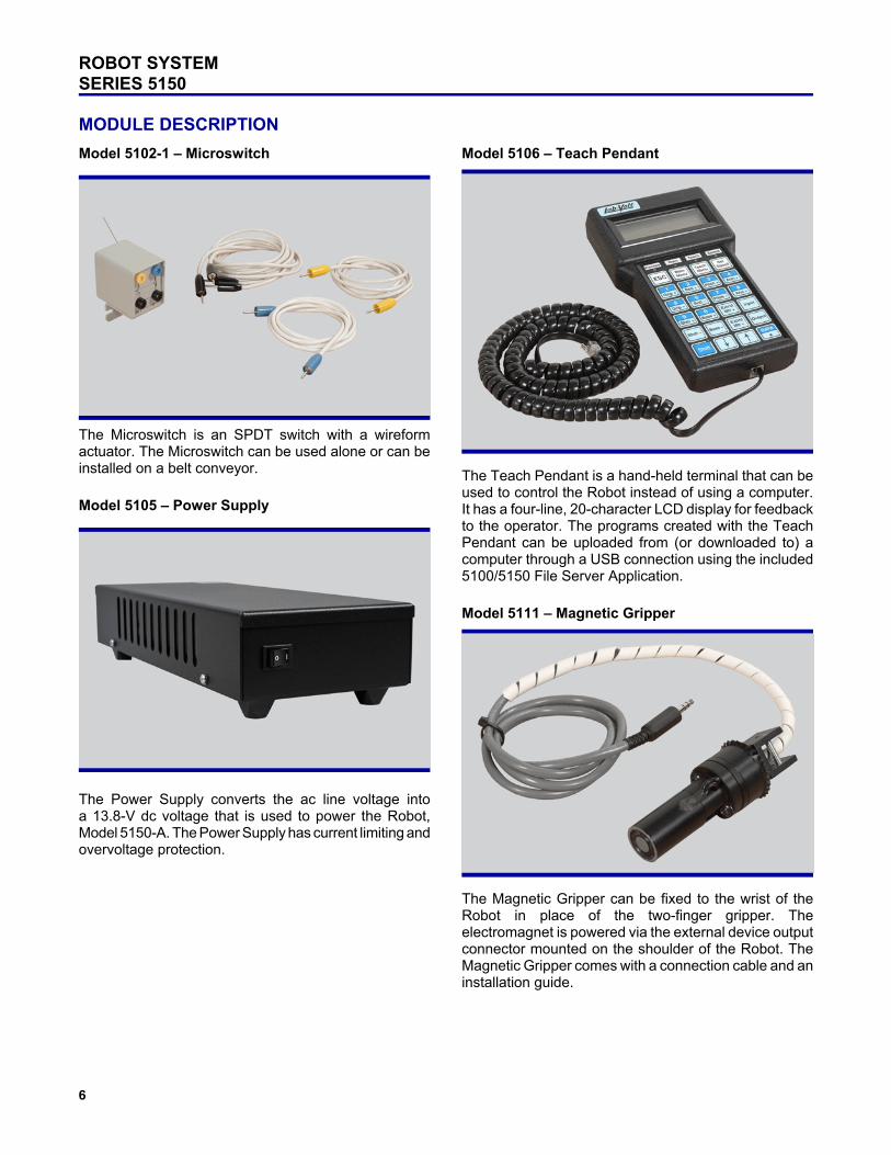
Model 5102-1 – Microswitch
The Microswitch is an SPDT switch with a wireformactuator. The Microswitch can be used alone or can beinstalled on a belt conveyor.
Model 5105 – Power Supply
The Power Supply converts the ac line voltage intoa 13.8-V dc voltage that is used to power the Robot,Model 5150-A. The Power Supply has current limiting andovervoltage protection.
Model 5106 – Teach Pendant
The Teach Pendant is a hand-held terminal that can beused to control the Robot instead of using a computer.It has a four-line, 20-character LCD display for feedbackto the operator. The programs created with the TeachPendant can be uploaded from (or downloaded to) acomputer through a USB connection using the included5100/5150 File Server Application.
Model 5111 – Magnetic Gripper
The Magnetic Gripper can be fixed to the wrist of theRobot in place of the two-finger gripper. Theelectromagnet is powered via the external device outputconnector mounted on the shoulder of the Robot. TheMagnetic Gripper comes with a connection cable and aninstallation guide.
7
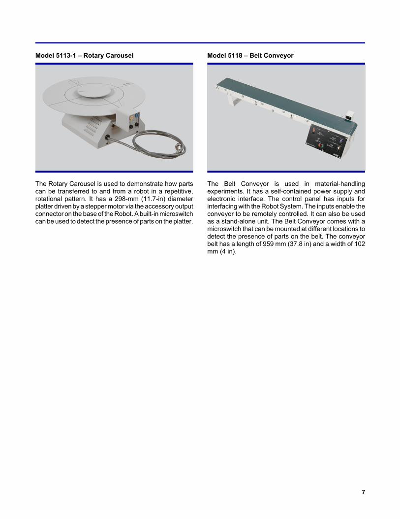
Model 5113-1 – Rotary Carousel
The Rotary Carousel is used to demonstrate how partscan be transferred to and from a robot in a repetitive,rotational pattern. It has a 298-mm (11.7-in) diameterplatter driven by a stepper motor via the accessory outputconnector on the base of the Robot. A built-in microswitchcan be used to detect the presence of parts on the platter.
Model 5118 – Belt Conveyor
The Belt Conveyor is used in material-handlingexperiments. It has a self-contained power supply andelectronic interface. The control panel has inputs forinterfacing with the Robot System. The inputs enable theconveyor to be remotely controlled. It can also be usedas a stand-alone unit. The Belt Conveyor comes with amicroswitch that can be mounted at different locations todetect the presence of parts on the belt. The conveyorbelt has a length of 959 mm (37.8 in) and a width of 102mm (4 in).
ROBOT SYSTEMSERIES 5150
8
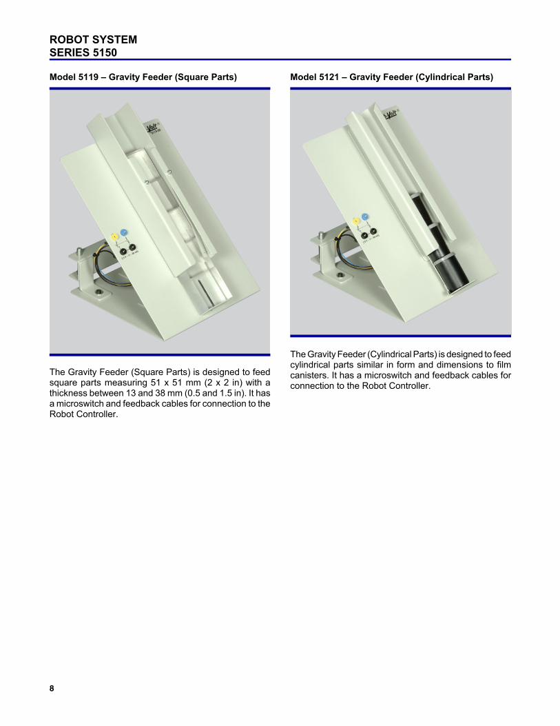
Model 5119 – Gravity Feeder (Square Parts)
The Gravity Feeder (Square Parts) is designed to feedsquare parts measuring 51 x 51 mm (2 x 2 in) with athickness between 13 and 38 mm (0.5 and 1.5 in). It hasa microswitch and feedback cables for connection to theRobot Controller.
Model 5121 – Gravity Feeder (Cylindrical Parts)
The Gravity Feeder (Cylindrical Parts) is designed to feedcylindrical parts similar in form and dimensions to filmcanisters. It has a microswitch and feedback cables forconnection to the Robot Controller.
9
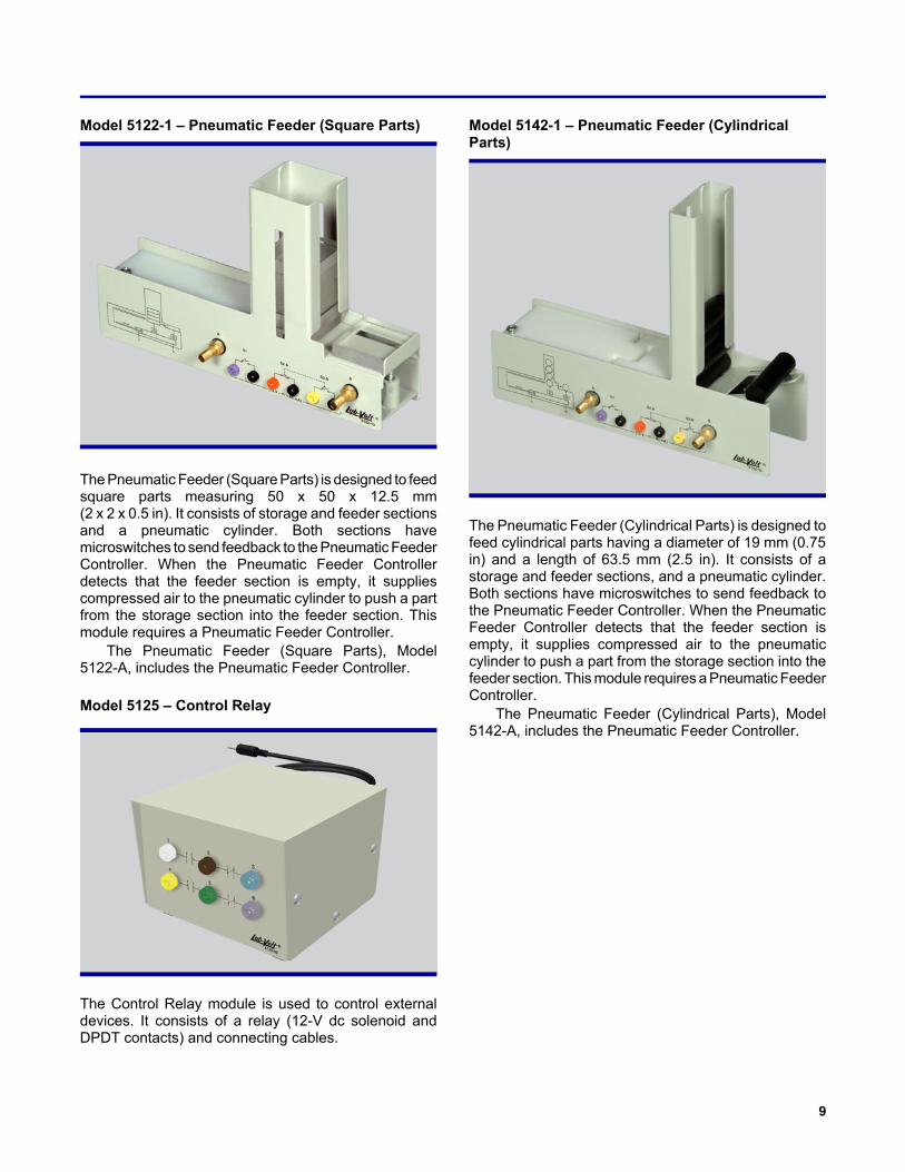
Model 5122-1 – Pneumatic Feeder (Square Parts)
The Pneumatic Feeder (Square Parts) is designed to feedsquare parts measuring 50 x 50 x 12.5 mm(2 x 2 x 0.5 in). It consists of storage and feeder sectionsand a pneumatic cylinder. Both sections havemicroswitches to send feedback to the Pneumatic FeederController. When the Pneumatic Feeder Controllerdetects that the feeder section is empty, it suppliescompressed air to the pneumatic cylinder to push a partfrom the storage section into the feeder section. Thismodule requires a Pneumatic Feeder Controller.
The Pneumatic Feeder (Square Parts), Model5122-A, includes the Pneumatic Feeder Controller.
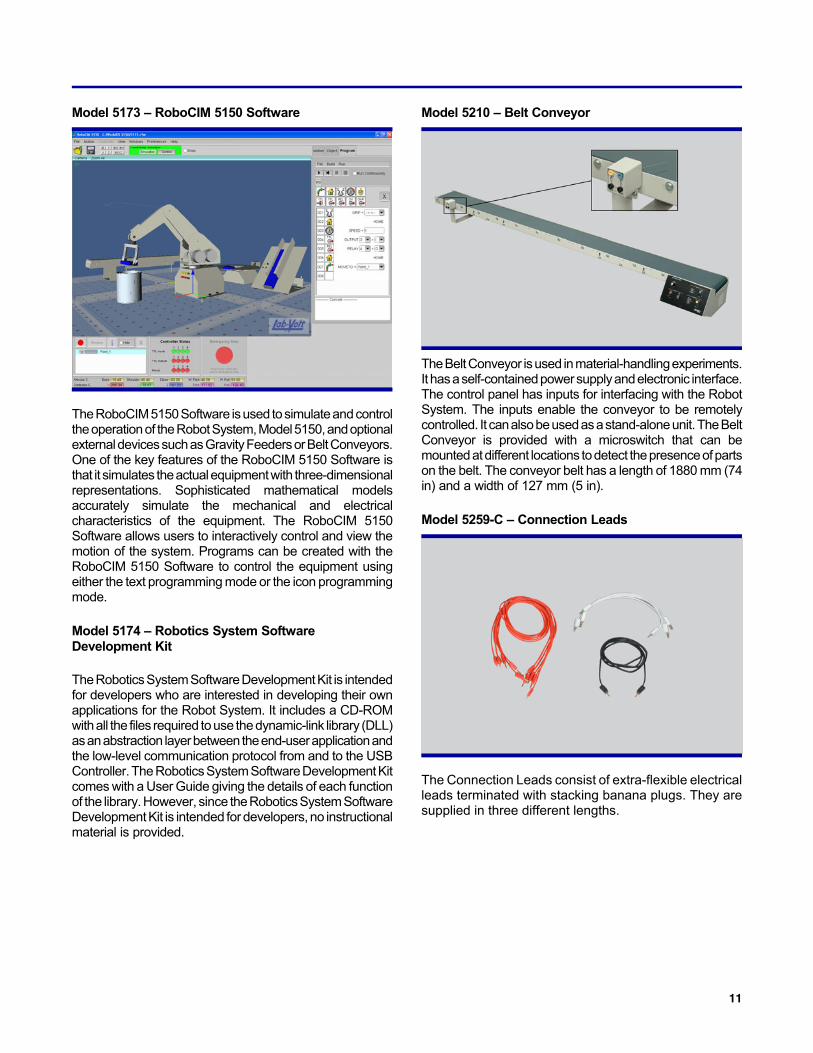
Model 5125 – Control Relay
The Control Relay module is used to control externaldevices. It consists of a relay (12-V dc solenoid andDPDT contacts) and connecting cables.
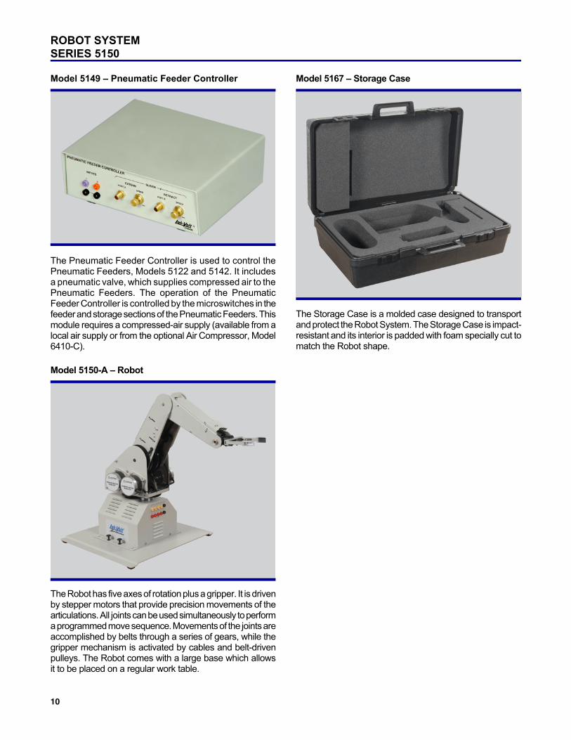
Model 5142-1 – Pneumatic Feeder (CylindricalParts)
The Pneumatic Feeder (Cylindrical Parts) is designed tofeed cylindrical parts having a diameter of 19 mm (0.75in) and a length of 63.5 mm (2.5 in). It consists of astorage and feeder sections, and a pneumatic cylinder.Both sections have microswitches to send feedback tothe Pneumatic Feeder Controller. When the PneumaticFeeder Controller detects that the feeder section isempty, it supplies compressed air to the pneumaticcylinder to push a part from the storage section into thefeeder section. This module requires a Pneumatic FeederController.
The Pneumatic Feeder (Cylindrical Parts), Model5142-A, includes the Pneumatic Feeder Controller.
ROBOT SYSTEMSERIES 5150
10
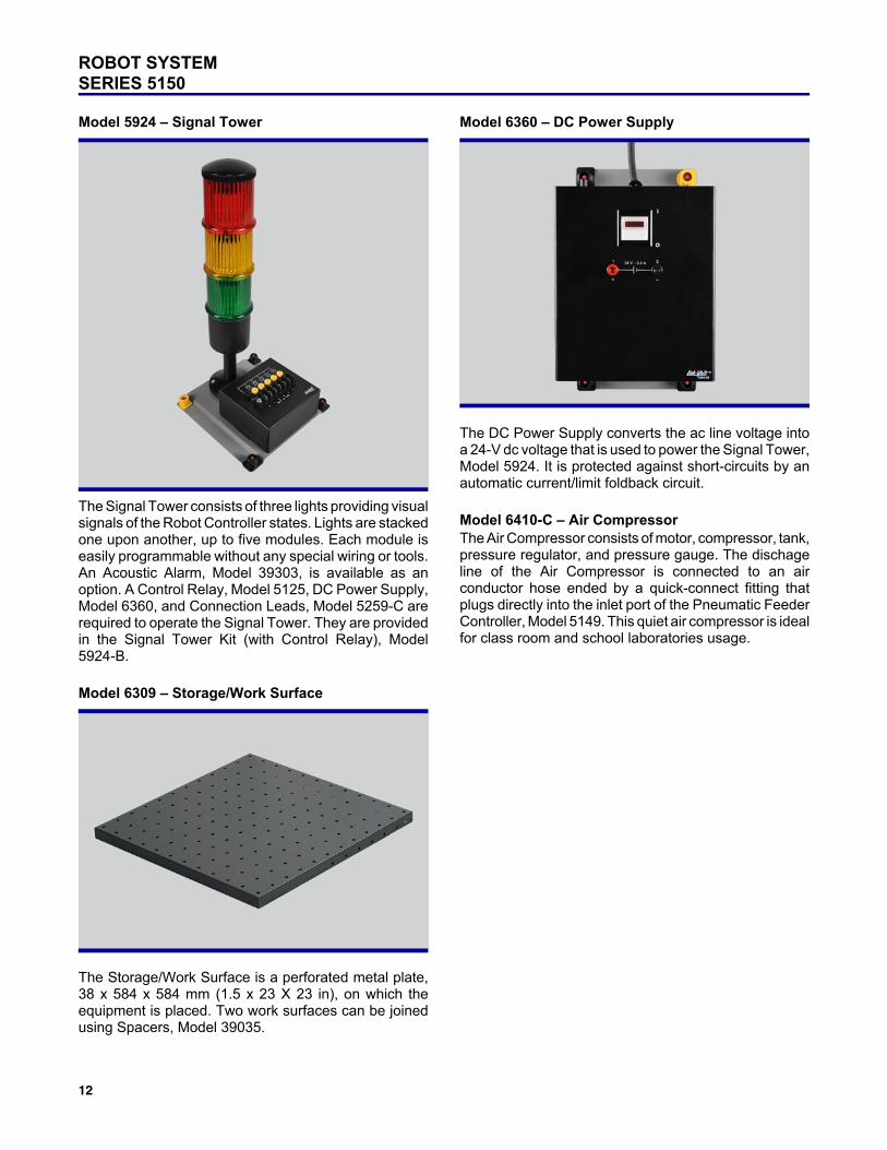
Model 5149 – Pneumatic Feeder Controller
The Pneumatic Feeder Controller is used to control thePneumatic Feeders, Models 5122 and 5142. It includesa pneumatic valve, which supplies compressed air to thePneumatic Feeders. The operation of the PneumaticFeeder Controller is controlled by the microswitches in thefeeder and storage sections of the Pneumatic Feeders. Thismodule requires a compressed-air supply (available from alocal air supply or from the optional Air Compressor, Model6410-C).
Model 5150-A – Robot
The Robot has five axes of rotation plus a gripper. It is drivenby stepper motors that provide precision movements of thearticulations. All joints can be used simultaneously to performa programmed move sequence. Movements of the joints areaccomplished by belts through a series of gears, while thegripper mechanism is activated by cables and belt-drivenpulleys. The Robot comes with a large base which allowsit to be placed on a regular work table.
Model 5167 – Storage Case
The Storage Case is a molded case designed to transportand protect the Robot System. The Storage Case is impact-resistant and its interior is padded with foam specially cut tomatch the Robot shape.
11
Model 5173 – RoboCIM 5150 Software
The RoboCIM 5150 Software is used to simulate and controlthe operation of the Robot System, Model 5150, and optionalexternal devices such as Gravity Feeders or Belt Conveyors.One of the key features of the RoboCIM 5150 Software isthat it simulates the actual equipment with three-dimensionalrepresentations. Sophisticated mathematical modelsaccurately simulate the mechanical and electricalcharacteristics of the equipment. The RoboCIM 5150Software allows users to interactively control and view themotion of the system. Programs can be created with theRoboCIM 5150 Software to control the equipment usingeither the text programming mode or the icon programmingmode.
Model 5174 – Robotics System SoftwareDevelopment Kit
The Robotics System Software Development Kit is intendedfor developers who are interested in developing their ownapplications for the Robot System. It includes a CD-ROMwith all the files required to use the dynamic-link library (DLL)as an abstraction layer between the end-user application andthe low-level communication protocol from and to the USBController. The Robotics System Software Development Kitcomes with a User Guide giving the details of each functionof the library. However, since the Robotics System SoftwareDevelopment Kit is intended for developers, no instructionalmaterial is provided.
Model 5210 – Belt Conveyor
The Belt Conveyor is used in material-handling experiments.It has a self-contained power supply and electronic interface.The control panel has inputs for interfacing with the RobotSystem. The inputs enable the conveyor to be remotelycontrolled. It can also be used as a stand-alone unit. The BeltConveyor is provided with a microswitch that can bemounted at different locations to detect the presence of partson the belt. The conveyor belt has a length of 1880 mm (74in) and a width of 127 mm (5 in).
Model 5259-C – Connection Leads
The Connection Leads consist of extra-flexible electricalleads terminated with stacking banana plugs. They aresupplied in three different lengths.
ROBOT SYSTEMSERIES 5150
12
Model 5924 – Signal Tower
The Signal Tower consists of three lights providing visualsignals of the Robot Controller states. Lights are stackedone upon another, up to five modules. Each module iseasily programmable without any special wiring or tools.An Acoustic Alarm, Model 39303, is available as anoption. A Control Relay, Model 5125, DC Power Supply,Model 6360, and Connection Leads, Model 5259-C arerequired to operate the Signal Tower. They are providedin the Signal Tower Kit (with Control Relay), Model5924-B.
Model 6309 – Storage/Work Surface
The Storage/Work Surface is a perforated metal plate,38 x 584 x 584 mm (1.5 x 23 X 23 in), on which theequipment is placed. Two work surfaces can be joinedusing Spacers, Model 39035.
Model 6360 – DC Power Supply
The DC Power Supply converts the ac line voltage intoa 24-V dc voltage that is used to power the Signal Tower,Model 5924. It is protected against short-circuits by anautomatic current/limit foldback circuit.
Model 6410-C – Air CompressorThe Air Compressor consists of motor, compressor, tank,pressure regulator, and pressure gauge. The dischageline of the Air Compressor is connected to an airconductor hose ended by a quick-connect fitting thatplugs directly into the inlet port of the Pneumatic FeederController, Model 5149. This quiet air compressor is idealfor class room and school laboratories usage.
13
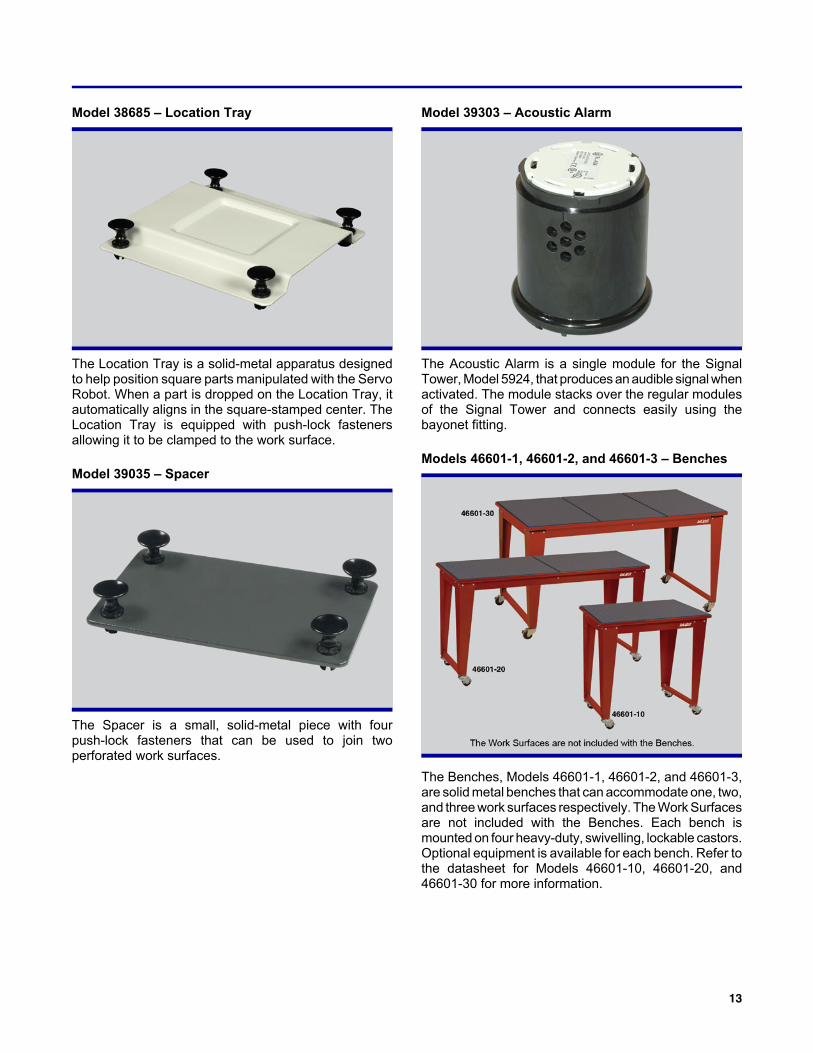
Model 38685 – Location Tray
The Location Tray is a solid-metal apparatus designedto help position square parts manipulated with the ServoRobot. When a part is dropped on the Location Tray, itautomatically aligns in the square-stamped center. TheLocation Tray is equipped with push-lock fastenersallowing it to be clamped to the work surface.
Model 39035 – Spacer
The Spacer is a small, solid-metal piece with fourpush-lock fasteners that can be used to join twoperforated work surfaces.
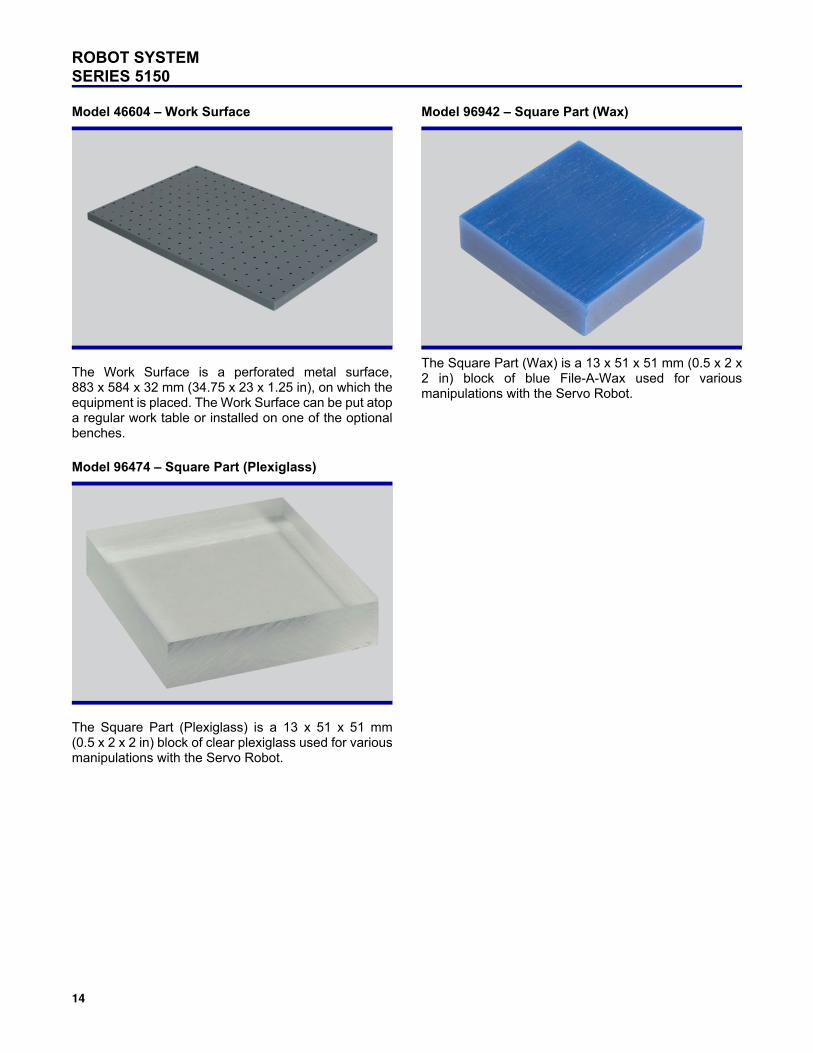
Model 39303 – Acoustic Alarm
The Acoustic Alarm is a single module for the SignalTower, Model 5924, that produces an audible signal whenactivated. The module stacks over the regular modulesof the Signal Tower and connects easily using thebayonet fitting.
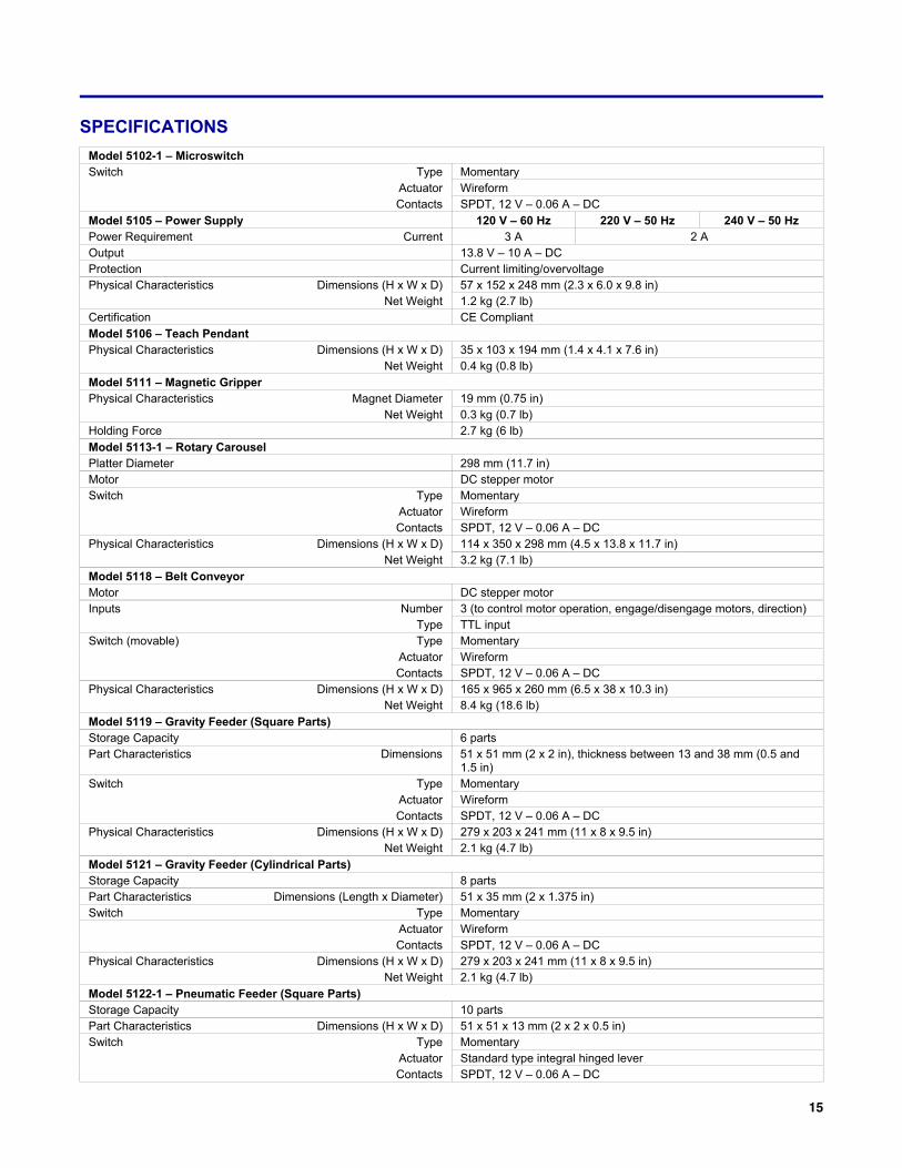
Models 46601-1, 46601-2, and 46601-3 – Benches
The Benches, Models 46601-1, 46601-2, and 46601-3,are solid metal benches that can accommodate one, two,and three work surfaces respectively. The Work Surfacesare not included with the Benches. Each bench ismounted on four heavy-duty, swivelling, lockable castors.Optional equipment is available for each bench. Refer tothe datasheet for Models 46601-10, 46601-20, and46601-30 for more information.
ROBOT SYSTEMSERIES 5150
14
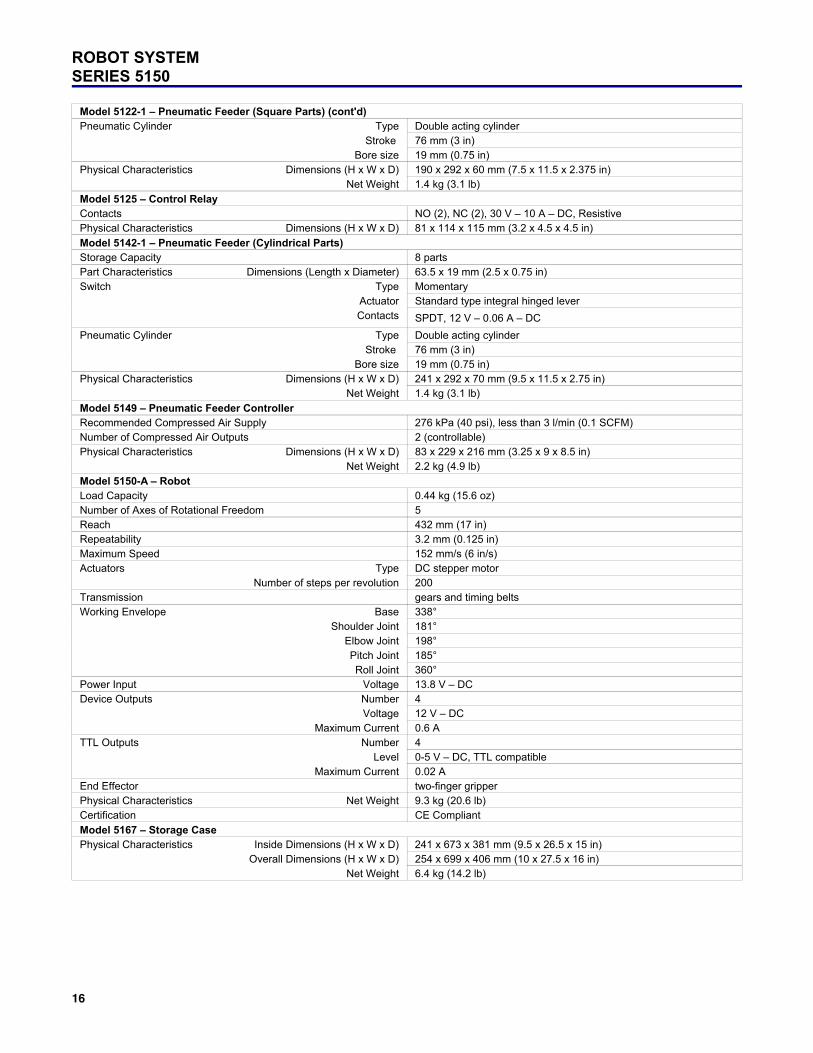
Model 46604 – Work Surface
The Work Surface is a perforated metal surface,883 x 584 x 32 mm (34.75 x 23 x 1.25 in), on which theequipment is placed. The Work Surface can be put atopa regular work table or installed on one of the optionalbenches.
Model 96474 – Square Part (Plexiglass)
The Square Part (Plexiglass) is a 13 x 51 x 51 mm(0.5 x 2 x 2 in) block of clear plexiglass used for variousmanipulations with the Servo Robot.
Model 96942 – Square Part (Wax)
The Square Part (Wax) is a 13 x 51 x 51 mm (0.5 x 2 x2 in) block of blue File-A-Wax used for variousmanipulations with the Servo Robot.
15
SPECIFICATIONS
Model 5102-1 – MicroswitchSwitch Type Momentary
Actuator WireformContacts SPDT, 12 V – 0.06 A – DC
Model 5105 – Power Supply 120 V – 60 Hz 220 V – 50 Hz 240 V – 50 HzPower Requirement Current 3 A 2 AOutput 13.8 V – 10 A – DCProtection Current limiting/overvoltagePhysical Characteristics Dimensions (H x W x D) 57 x 152 x 248 mm (2.3 x 6.0 x 9.8 in)
Net Weight 1.2 kg (2.7 lb)Certification CE Compliant
Model 5106 – Teach PendantPhysical Characteristics Dimensions (H x W x D) 35 x 103 x 194 mm (1.4 x 4.1 x 7.6 in)
Net Weight 0.4 kg (0.8 lb)
Model 5111 – Magnetic GripperPhysical Characteristics Magnet Diameter 19 mm (0.75 in)
Net Weight 0.3 kg (0.7 lb)Holding Force 2.7 kg (6 lb)
Model 5113-1 – Rotary CarouselPlatter Diameter 298 mm (11.7 in)Motor DC stepper motorSwitch Type Momentary
Actuator WireformContacts SPDT, 12 V – 0.06 A – DC
Physical Characteristics Dimensions (H x W x D) 114 x 350 x 298 mm (4.5 x 13.8 x 11.7 in)Net Weight 3.2 kg (7.1 lb)
Model 5118 – Belt ConveyorMotor DC stepper motor Inputs Number 3 (to control motor operation, engage/disengage motors, direction)
Type TTL inputSwitch (movable) Type Momentary
Actuator WireformContacts SPDT, 12 V – 0.06 A – DC
Physical Characteristics Dimensions (H x W x D) 165 x 965 x 260 mm (6.5 x 38 x 10.3 in)Net Weight 8.4 kg (18.6 lb)
Model 5119 – Gravity Feeder (Square Parts)Storage Capacity 6 partsPart Characteristics Dimensions 51 x 51 mm (2 x 2 in), thickness between 13 and 38 mm (0.5 and
1.5 in)Switch Type Momentary
Actuator WireformContacts SPDT, 12 V – 0.06 A – DC
Physical Characteristics Dimensions (H x W x D) 279 x 203 x 241 mm (11 x 8 x 9.5 in)Net Weight 2.1 kg (4.7 lb)
Model 5121 – Gravity Feeder (Cylindrical Parts)Storage Capacity 8 partsPart Characteristics Dimensions (Length x Diameter) 51 x 35 mm (2 x 1.375 in)Switch Type Momentary
Actuator WireformContacts SPDT, 12 V – 0.06 A – DC
Physical Characteristics Dimensions (H x W x D) 279 x 203 x 241 mm (11 x 8 x 9.5 in)Net Weight 2.1 kg (4.7 lb)
Model 5122-1 – Pneumatic Feeder (Square Parts)Storage Capacity 10 partsPart Characteristics Dimensions (H x W x D) 51 x 51 x 13 mm (2 x 2 x 0.5 in)Switch Type Momentary
Actuator Standard type integral hinged leverContacts SPDT, 12 V – 0.06 A – DC
ROBOT SYSTEMSERIES 5150
16
Model 5122-1 – Pneumatic Feeder (Square Parts) (cont'd)Pneumatic Cylinder Type Double acting cylinder
Stroke 76 mm (3 in)Bore size 19 mm (0.75 in)
Physical Characteristics Dimensions (H x W x D) 190 x 292 x 60 mm (7.5 x 11.5 x 2.375 in)Net Weight 1.4 kg (3.1 lb)
Model 5125 – Control RelayContacts NO (2), NC (2), 30 V – 10 A – DC, ResistivePhysical Characteristics Dimensions (H x W x D) 81 x 114 x 115 mm (3.2 x 4.5 x 4.5 in)
Model 5142-1 – Pneumatic Feeder (Cylindrical Parts)Storage Capacity 8 partsPart Characteristics Dimensions (Length x Diameter) 63.5 x 19 mm (2.5 x 0.75 in)Switch Type Momentary
Actuator Standard type integral hinged leverContacts SPDT, 12 V – 0.06 A – DC
Pneumatic Cylinder Type Double acting cylinderStroke 76 mm (3 in)
Bore size 19 mm (0.75 in)Physical Characteristics Dimensions (H x W x D) 241 x 292 x 70 mm (9.5 x 11.5 x 2.75 in)
Net Weight 1.4 kg (3.1 lb)
Model 5149 – Pneumatic Feeder ControllerRecommended Compressed Air Supply 276 kPa (40 psi), less than 3 l/min (0.1 SCFM)Number of Compressed Air Outputs 2 (controllable)Physical Characteristics Dimensions (H x W x D) 83 x 229 x 216 mm (3.25 x 9 x 8.5 in)
Net Weight 2.2 kg (4.9 lb)
Model 5150-A – RobotLoad Capacity 0.44 kg (15.6 oz)Number of Axes of Rotational Freedom 5Reach 432 mm (17 in)Repeatability 3.2 mm (0.125 in)Maximum Speed 152 mm/s (6 in/s)Actuators Type DC stepper motor
Number of steps per revolution 200Transmission gears and timing beltsWorking Envelope Base 338°
Shoulder Joint 181°Elbow Joint 198°Pitch Joint 185°Roll Joint 360°
Power Input Voltage 13.8 V – DC Device Outputs Number 4
Voltage 12 V – DC Maximum Current 0.6 A
TTL Outputs Number 4Level 0-5 V – DC, TTL compatible
Maximum Current 0.02 AEnd Effector two-finger gripperPhysical Characteristics Net Weight 9.3 kg (20.6 lb)Certification CE Compliant
Model 5167 – Storage CasePhysical Characteristics Inside Dimensions (H x W x D) 241 x 673 x 381 mm (9.5 x 26.5 x 15 in)
Overall Dimensions (H x W x D) 254 x 699 x 406 mm (10 x 27.5 x 16 in)Net Weight 6.4 kg (14.2 lb)
17
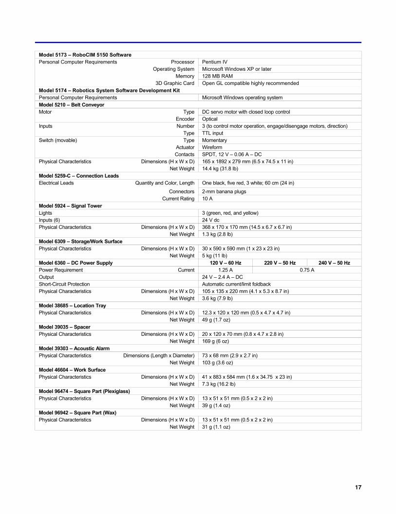
Model 5173 – RoboCIM 5150 SoftwarePersonal Computer Requirements Processor Pentium IV
Operating System Microsoft Windows XP or laterMemory 128 MB RAM
3D Graphic Card Open GL compatible highly recommended
Model 5174 – Robotics System Software Development KitPersonal Computer Requirements Microsoft Windows operating system
Model 5210 – Belt ConveyorMotor Type DC servo motor with closed loop control
Encoder OpticalInputs Number 3 (to control motor operation, engage/disengage motors, direction)
Type TTL inputSwitch (movable) Type Momentary
Actuator WireformContacts SPDT, 12 V – 0.06 A – DC
Physical Characteristics Dimensions (H x W x D) 165 x 1892 x 279 mm (6.5 x 74.5 x 11 in)Net Weight 14.4 kg (31.8 lb)
Model 5259-C – Connection LeadsElectrical Leads Quantity and Color, Length One black, five red, 3 white; 60 cm (24 in)
Connectors 2-mm banana plugsCurrent Rating 10 A
Model 5924 – Signal TowerLights 3 (green, red, and yellow)Inputs (6) 24 V dcPhysical Characteristics Dimensions (H x W x D) 368 x 170 x 170 mm (14.5 x 6.7 x 6.7 in)
Net Weight 1.3 kg (2.8 lb)
Model 6309 – Storage/Work SurfacePhysical Characteristics Dimensions (H x W x D) 30 x 590 x 590 mm (1 x 23 x 23 in)
Net Weight 5 kg (11 lb)
Model 6360 – DC Power Supply 120 V – 60 Hz 220 V – 50 Hz 240 V – 50 HzPower Requirement Current 1.25 A 0.75 AOutput 24 V – 2.4 A – DCShort-Circuit Protection Automatic current/limit foldbackPhysical Characteristics Dimensions (H x W x D) 105 x 135 x 220 mm (4.1 x 5.3 x 8.7 in)
Net Weight 3.6 kg (7.9 lb)
Model 38685 – Location TrayPhysical Characteristics Dimensions (H x W x D) 12.3 x 120 x 120 mm (0.5 x 4.7 x 4.7 in)
Net Weight 49 g (1.7 oz)
Model 39035 – SpacerPhysical Characteristics Dimensions (H x W x D) 20 x 120 x 70 mm (0.8 x 4.7 x 2.8 in)
Net Weight 169 g (6 oz)
Model 39303 – Acoustic AlarmPhysical Characteristics Dimensions (Length x Diameter) 73 x 68 mm (2.9 x 2.7 in)
Net Weight 103 g (3.6 oz)
Model 46604 – Work SurfacePhysical Characteristics Dimensions (H x W x D) 41 x 883 x 584 mm (1.6 x 34.75 x 23 in)
Net Weight 7.3 kg (16.2 lb)
Model 96474 – Square Part (Plexiglass)Physical Characteristics Dimensions (H x W x D) 13 x 51 x 51 mm (0.5 x 2 x 2 in)
Net Weight 39 g (1.4 oz)
Model 96942 – Square Part (Wax)Physical Characteristics Dimensions (H x W x D) 13 x 51 x 51 mm (0.5 x 2 x 2 in)
Net Weight 31 g (1.1 oz)
ROBOT SYSTEMSERIES 5150
18
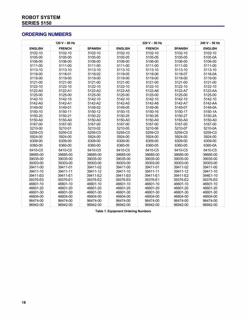
ORDERING NUMBERS
120 V – 60 Hz 220 V – 50 Hz 240 V – 50 Hz
ENGLISH FRENCH SPANISH ENGLISH FRENCH SPANISH ENGLISH
5102-10 5102-10 5102-10 5102-10 5102-10 5102-10 5102-105105-00 5105-00 5105-00 5105-05 5105-05 5105-05 5105-0A5106-00 5106-00 5106-00 5106-00 5106-00 5106-00 5106-005111-00 5111-00 5111-00 5111-00 5111-00 5111-00 5111-005113-10 5113-10 5113-10 5113-10 5113-10 5113-10 5113-105118-00 5118-01 5118-02 5118-05 5118-06 5118-07 5118-0A5119-00 5119-00 5119-00 5119-00 5119-00 5119-00 5119-005121-00 5121-00 5121-00 5121-00 5121-00 5121-00 5121-005122-10 5122-10 5122-10 5122-10 5122-10 5122-10 5122-105122-A0 5122-A1 5122-A2 5122-A5 5122-A6 5122-A7 5122-AA5125-00 5125-00 5125-00 5125-00 5125-00 5125-00 5125-005142-10 5142-10 5142-10 5142-10 5142-10 5142-10 5142-105142-A0 5142-A1 5142-A2 5142-A5 5142-A6 5142-A7 5142-AA5149-00 5149-01 5149-02 5149-05 5149-06 5149-07 5149-0A5150-10 5150-11 5150-12 5150-15 5150-16 5150-17 5150-1A5150-20 5150-21 5150-22 5150-25 5150-26 5150-27 5150-2A5150-A0 5150-A0 5150-A0 5150-A0 5150-A0 5150-A0 5150-A05167-00 5167-00 5167-00 5167-00 5167-00 5167-00 5167-005210-00 5210-01 5210-02 5210-05 5210-06 5210-07 5210-0A5259-C0 5259-C0 5259-C0 5259-C0 5259-C0 5259-C0 5259-C05924-00 5924-00 5924-00 5924-00 5924-00 5924-00 5924-006309-00 6309-00 6309-00 6309-00 6309-00 6309-00 6309-006360-00 6360-00 6360-00 6360-05 6360-05 6360-05 6360-0A6410-C0 6410-C0 6410-C0 6410-C5 6410-C5 6410-C5 6410-C538685-00 38685-00 38685-00 38685-00 38685-00 38685-00 38685-0039035-00 39035-00 39035-00 39035-00 39035-00 39035-00 39035-0039303-00 39303-00 39303-00 39303-00 39303-00 39303-00 39303-0039411-00 39411-01 39411-02 39411-00 39411-01 39411-02 39411-0039411-10 39411-11 39411-12 39411-10 39411-11 39411-12 39411-1039411-E0 39411-E1 39411-E2 39411-E0 39411-E1 39411-E2 394E1-1039376-E0 39376-E1 39376-E2 39376-E0 39376-E1 39376-E2 39376-E046601-10 46601-10 46601-10 46601-10 46601-10 46601-10 46601-1046601-20 46601-20 46601-20 46601-20 46601-20 46601-20 46601-2046601-30 46601-30 46601-30 46601-30 46601-30 46601-30 46601-3046604-00 46604-00 46604-00 46604-00 46604-00 46604-00 46604-0096474-00 96474-00 96474-00 96474-00 96474-00 96474-00 96474-0096942-00 96942-00 96942-00 96942-00 96942-00 96942-00 96942-00
Table 1. Equipment Ordering Numbers
19
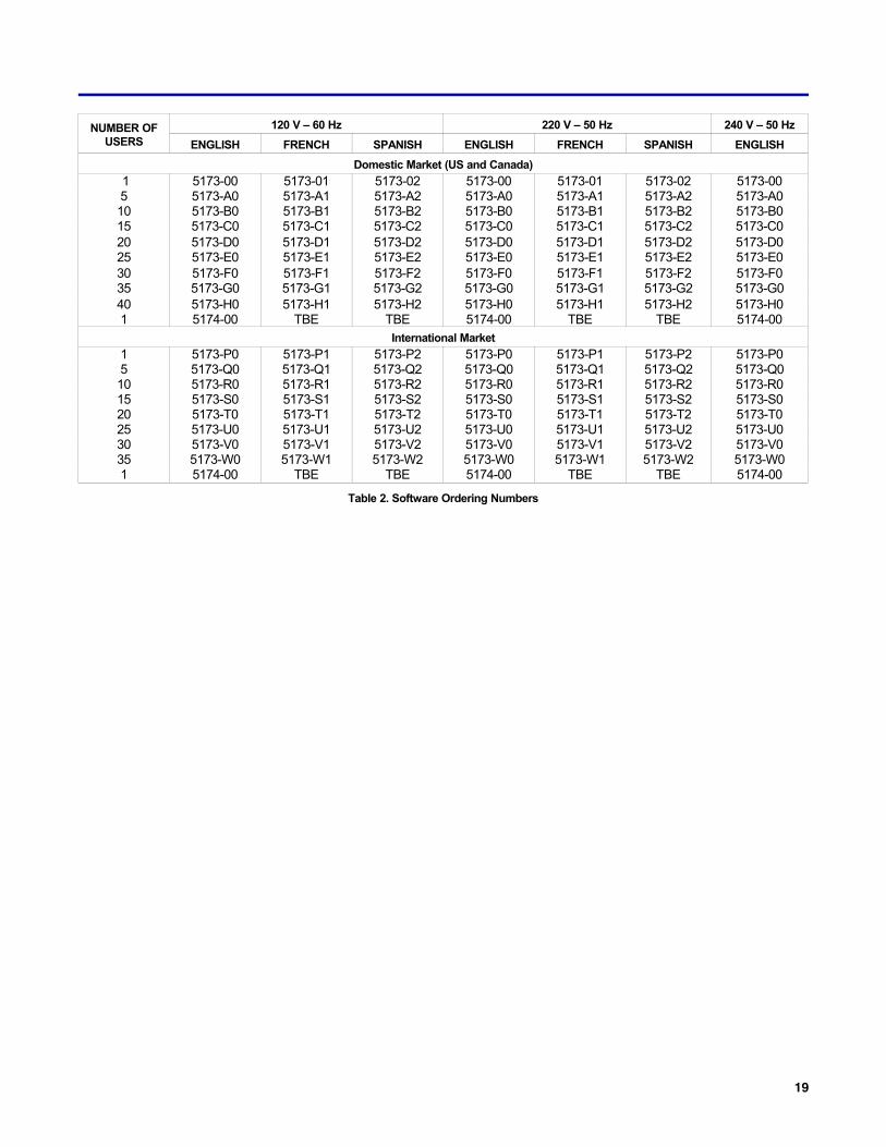
NUMBER OFUSERS
120 V – 60 Hz 220 V – 50 Hz 240 V – 50 Hz
ENGLISH FRENCH SPANISH ENGLISH FRENCH SPANISH ENGLISH
Domestic Market (US and Canada)
1 5173-00 5173-01 5173-02 5173-00 5173-01 5173-02 5173-005 5173-A0 5173-A1 5173-A2 5173-A0 5173-A1 5173-A2 5173-A010 5173-B0 5173-B1 5173-B2 5173-B0 5173-B1 5173-B2 5173-B015 5173-C0 5173-C1 5173-C2 5173-C0 5173-C1 5173-C2 5173-C020 5173-D0 5173-D1 5173-D2 5173-D0 5173-D1 5173-D2 5173-D025 5173-E0 5173-E1 5173-E2 5173-E0 5173-E1 5173-E2 5173-E030 5173-F0 5173-F1 5173-F2 5173-F0 5173-F1 5173-F2 5173-F035 5173-G0 5173-G1 5173-G2 5173-G0 5173-G1 5173-G2 5173-G040 5173-H0 5173-H1 5173-H2 5173-H0 5173-H1 5173-H2 5173-H01 5174-00 TBE TBE 5174-00 TBE TBE 5174-00
International Market
1 5173-P0 5173-P1 5173-P2 5173-P0 5173-P1 5173-P2 5173-P05 5173-Q0 5173-Q1 5173-Q2 5173-Q0 5173-Q1 5173-Q2 5173-Q010 5173-R0 5173-R1 5173-R2 5173-R0 5173-R1 5173-R2 5173-R015 5173-S0 5173-S1 5173-S2 5173-S0 5173-S1 5173-S2 5173-S020 5173-T0 5173-T1 5173-T2 5173-T0 5173-T1 5173-T2 5173-T025 5173-U0 5173-U1 5173-U2 5173-U0 5173-U1 5173-U2 5173-U030 5173-V0 5173-V1 5173-V2 5173-V0 5173-V1 5173-V2 5173-V035 5173-W0 5173-W1 5173-W2 5173-W0 5173-W1 5173-W2 5173-W01 5174-00 TBE TBE 5174-00 TBE TBE 5174-00
Table 2. Software Ordering Numbers

Reflecting Lab-Volt's commitment to high quality standards in product, design, development, production, installation and service, our manufacturing and distributionfacility has received the ISO 9001 certification.
Lab-Volt reserves the right to make product improvements at any time and without notice and is not responsible for typographical errors. Lab-Volt recognizes all productnames used herein as trademarks or registered trademarks of their respective holders. © Lab-Volt 2013. All rights reserved.
94077-00 Rev. A4