transistor amplifier circuits, 4-1 - lab-volt · student manual 114 facet by lab-volt common...
TRANSCRIPT
Student Manual
112 FACET by Lab-Volt
Common Collector Circuit
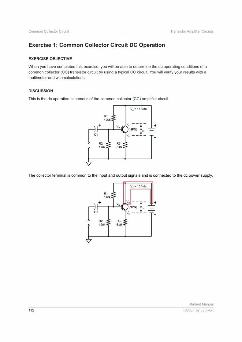
When you have completed this exercise, you will be able to determine the dc operating conditions of a
common collector (CC) transistor circuit by using a typical CC circuit. You will verify your results with a
multimeter and with calculations.
The collector terminal is common to the input and output signals and is connected to the dc power supply.
Student Manual
FACET by Lab-Volt 113
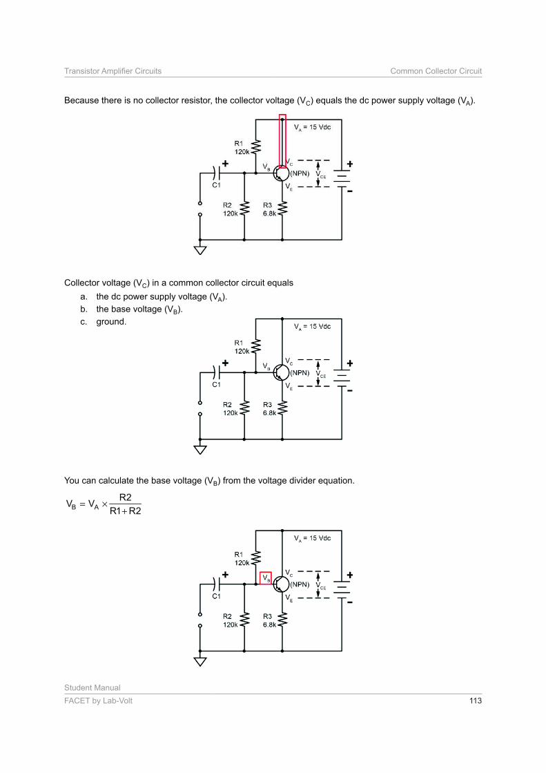
Because there is no collector resistor, the collector voltage (VC) equals the dc power supply voltage (VA).
Collector voltage (VC) in a common collector circuit equals
a. the dc power supply voltage (VA).
b. the base voltage (VB).
c. ground.
You can calculate the base voltage (VB) from the voltage divider equation.
B A
R2V V
R1 R2= ×
+

Student Manual
114 FACET by Lab-Volt
Common Collector Circuit
The emitter voltage (VE) is about 0.6 Vdc less than the base voltage when the transistor is operating
normally.
VE = VB – 0.6
To calculate emitter current (IE), use the values of emitter voltage and the emitter resistor in Ohm’s law.
EE
VI
R3=
The collector current is the difference between the emitter and base currents.
IC = IE – IB
Student Manual
FACET by Lab-Volt 115
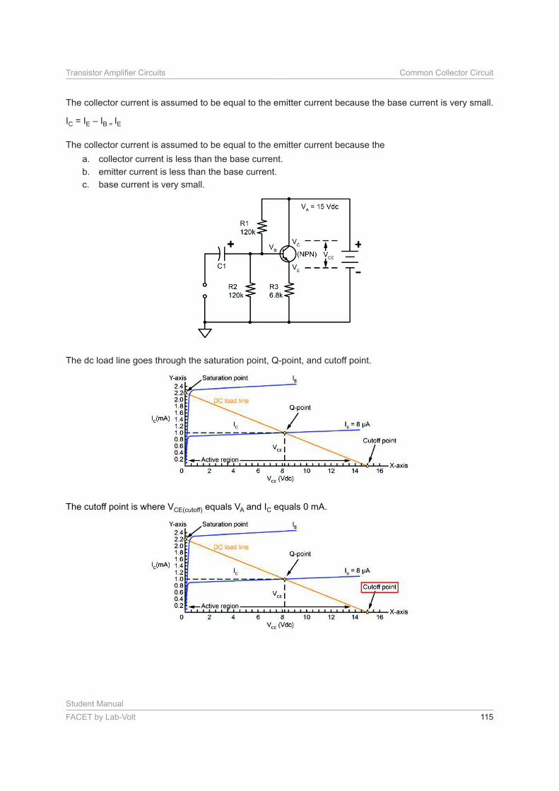
The collector current is assumed to be equal to the emitter current because the base current is very small.
IC = IE – IB = IE
The collector current is assumed to be equal to the emitter current because the
a. collector current is less than the base current.
b. emitter current is less than the base current.
c. base current is very small.
The dc load line goes through the saturation point, Q-point, and cutoff point.
The cutoff point is where VCE(cutoff) equals VA and IC equals 0 mA.

Student Manual
116 FACET by Lab-Volt
Common Collector Circuit
The saturation point is where IC(sat) equals VA CE equals 0.0 Vdc.
The cutoff point is where
a. VCE(cutoff) equals VA.
b. IC is 0 mA.
c. Both of the above.
Locate the COMMON COLLECTOR circuit block, and connect the circuit shown.
Measure the supply voltage (VA) with reference to ground.
VA = Vdc (Recall Value 1)
Student Manual
FACET by Lab-Volt 117
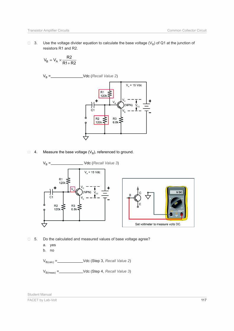
Use the voltage divider equation to calculate the base voltage (VB) of Q1 at the junction of
resistors R1 and R2.
B A
R2V V
R1 R2= ×
+
VB = Vdc (Recall Value 2)
Measure the base voltage (VB), referenced to ground.
VB = Vdc (Recall Value 3)
Do the calculated and measured values of base voltage agree?
a. yes
b. no
VB(calc) = Vdc (Step 3, Recall Value 2)
VB(meas) = Vdc (Step 4, Recall Value 3)
Student Manual
118 FACET by Lab-Volt
Common Collector Circuit
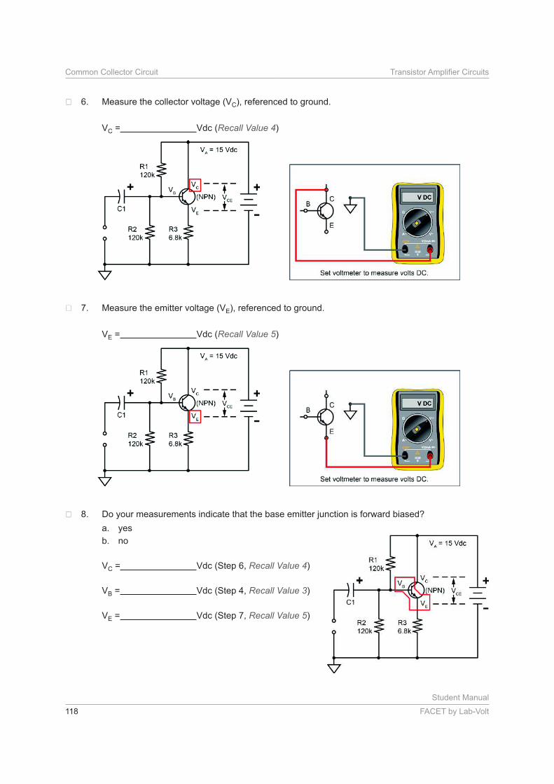
Measure the collector voltage (VC), referenced to ground.
VC = Vdc (Recall Value 4)
Measure the emitter voltage (VE), referenced to ground.
VE = Vdc (Recall Value 5)
Do your measurements indicate that the base emitter junction is forward biased?
a. yes
b. no
VC = Vdc (Step 6, Recall Value 4)
VB = Vdc (Step 4, Recall Value 3)
VE = Vdc (Step 7, Recall Value 5)
Student Manual
FACET by Lab-Volt 119
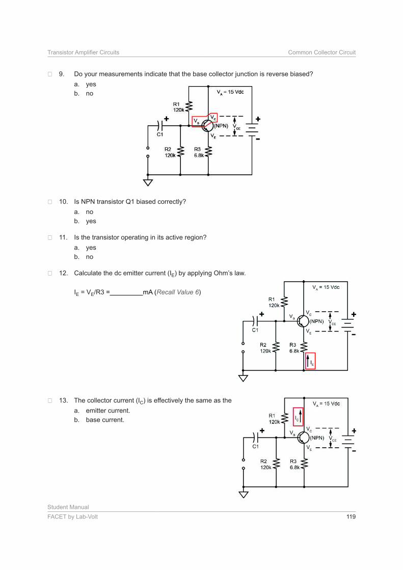
Do your measurements indicate that the base collector junction is reverse biased?
a. yes
b. no
Is NPN transistor Q1 biased correctly?
a. no
b. yes
Is the transistor operating in its active region?
a. yes
b. no
Calculate the dc emitter current (IE) by applying Ohm’s law.
IE = VE = mA (Recall Value 6)
The collector current (IC) is effectively the same as the
a. emitter current.
b. base current.
Student Manual
120 FACET by Lab-Volt
Common Collector Circuit
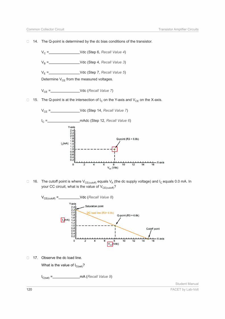
The Q-point is determined by the dc bias conditions of the transistor.
VC = Vdc (Step 6, Recall Value 4)
VB = Vdc (Step 4, Recall Value 3)
VE = Vdc (Step 7, Recall Value 5)
Determine VCE from the measured voltages.
VCE = Vdc (Recall Value 7)
The Q-point is at the intersection of IC on the Y-axis and VCE on the X-axis.
VCE = Vdc (Step 14, Recall Value 7)
IC = mAdc (Step 12, Recall Value 6)
The cutoff point is where VCE(cutoff) equals VA (the dc supply voltage) and IC equals 0.0 mA. In
your CC circuit, what is the value of VCE(cutoff)?
VCE(cutoff) = Vdc (Recall Value 8)
Observe the dc load line.
What is the value of IC(sat)?
IC(sat) = mA (Recall Value 9)
Student Manual
FACET by Lab-Volt 121
• A voltage divider circuit provides a constant dc base voltage to properly bias the transistor.
• Because there is no collector resistor, the collector voltage (VC) equals the dc supply voltage (VA).
• The emitter voltage (VE) is about 0.6 V less than the base voltage (VB) when the NPN transistor is
operating normally.
• The emitter and collector currents are considered essentially equal.
• For operation in the active region, the base-emitter junction is forward biased, and the base-collector
junction is reverse biased.
• The slope of the dc load line depends on the value of the emitter resistor (R3).
• The Q-point on the dc load line is the intersection of the operating collector current (IC) and the
collector-emitter voltage (VCE).
• The intersection of the dc load line and the Y-axis (IC) is the saturation point.
• The intersection of the dc load line and the X-axis (VCE) is the cutoff point (zero current).
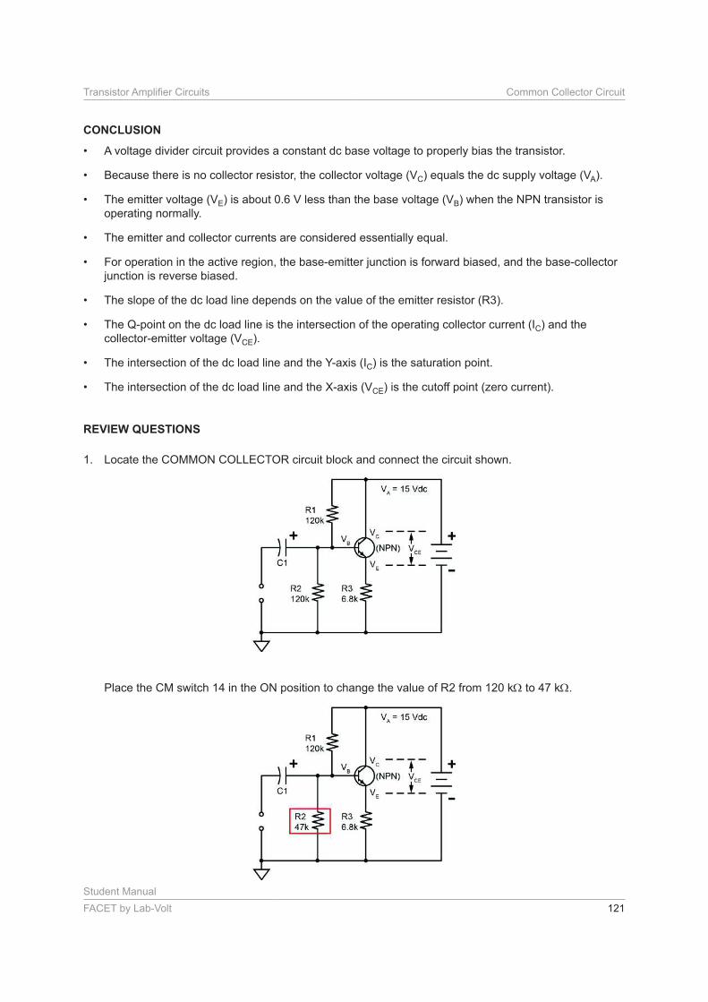
1. Locate the COMMON COLLECTOR circuit block and connect the circuit shown.
Place the CM switch 14 in the ON position to change the value of R2 from 120 k to 47 k .
Student Manual
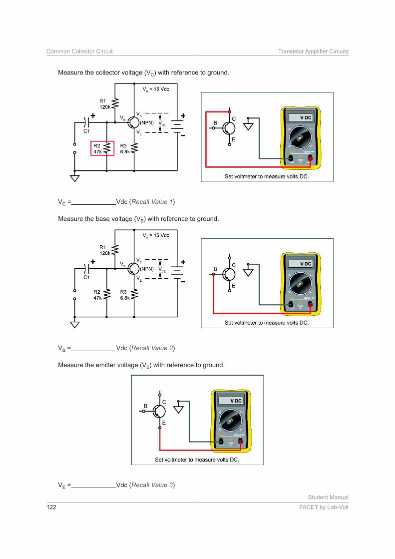
122 FACET by Lab-Volt
Common Collector Circuit
Measure the collector voltage (VC) with reference to ground.
VC = Vdc (Recall Value 1)
Measure the base voltage (VB) with reference to ground.
VB = Vdc (Recall Value 2)
Measure the emitter voltage (VE) with reference to ground.
VE = Vdc (Recall Value 3)

Student Manual
FACET by Lab-Volt 123
Based on your measured values, the transistor is operating
a. at the saturation point.
b. in the active region.
c. at the cutoff point.
d. at an optimum Q-point.
VC = Vdc (Step 1, Recall Value 1)
VB = Vdc (Step 1, Recall Value 2)
VE = Vdc (Step 1, Recall Value 3)
2. With R2 equal to 47 k , the emitter current (IE) is closest to
a. 0.519 mA.
b. 0.059 mA.
c. 0.155 mA.
d. 0.939 mA.
3. With R2 equal to 47 k , the
a. slope of the load line changes.
b. saturation point changes.
c. cutoff point changes.
d. Q-point changes, but the load line does not.
4. With R2 equal to 47 k , the new VCE is closest to
a. 11.47 Vdc
b. 0.61 Vdc.
c. 7.43 Vdc.
d. 15.00 Vdc.
5. In a CC transistor circuit, the collector voltage (VC) equals
a. VA – 0.6.
b. VB + VE.
c. VB – 0.6.
d. VA.
Make sure all CMs are cleared (turned off) before proceeding to the next section.