telephony training system, model 8086 - lab volt
TRANSCRIPT

Telecommunications Telephony
Analog Access to the Telephone Network
Courseware Sample 32964-F0

Order no.: 32964-00 First Edition Revision level: 01/2015
By the staff of Festo Didactic
© Festo Didactic Ltée/Ltd, Quebec, Canada 2001 Internet: www.festo-didactic.com e-mail: [email protected]
Printed in Canada All rights reserved ISBN 978-2-89289-541-4 (Printed version) Legal Deposit – Bibliothèque et Archives nationales du Québec, 2001 Legal Deposit – Library and Archives Canada, 2001
The purchaser shall receive a single right of use which is non-exclusive, non-time-limited and limited geographically to use at the purchaser's site/location as follows.
The purchaser shall be entitled to use the work to train his/her staff at the purchaser's site/location and shall also be entitled to use parts of the copyright material as the basis for the production of his/her own training documentation for the training of his/her staff at the purchaser's site/location with acknowledgement of source and to make copies for this purpose. In the case of schools/technical colleges, training centers, and universities, the right of use shall also include use by school and college students and trainees at the purchaser's site/location for teaching purposes.
The right of use shall in all cases exclude the right to publish the copyright material or to make this available for use on intranet, Internet and LMS platforms and databases such as Moodle, which allow access by a wide variety of users, including those outside of the purchaser's site/location.
Entitlement to other rights relating to reproductions, copies, adaptations, translations, microfilming and transfer to and storage and processing in electronic systems, no matter whether in whole or in part, shall require the prior consent of Festo Didactic GmbH & Co. KG.
Information in this document is subject to change without notice and does not represent a commitment on the part of Festo Didactic. The Festo materials described in this document are furnished under a license agreement or a nondisclosure agreement.
Festo Didactic recognizes product names as trademarks or registered trademarks of their respective holders.
All other trademarks are the property of their respective owners. Other trademarks and trade names may be used in this document to refer to either the entity claiming the marks and names or their products. Festo Didactic disclaims any proprietary interest in trademarks and trade names other than its own.

The fothe eq
S
Sa
ollowing safetuipment:
Symbol
afety and
ty and comm
DANGER inavoided, wi
WARNINGif not avoide
CAUTION iavoided, co
CAUTION uindicates a if not avoide
Caution, ris
Caution, ho
Caution, ris
Caution, lift
Caution, ha
Notice, non
Direct curre
Alternating
Both direct
Three-phas
Earth (grou
d Comm
on symbols m
ndicates a hazall result in deat
indicates a hazed, could result
ndicates a hazould result in mi
used without thhazard with a ped, may result
k of electric sh
ot surface
k of danger
ing hazard
and entangleme
-ionizing radiat
ent
current
and alternating
se alternating c
nd) terminal
mon Sym
may be used
Description
ard with a highth or serious inj
zard with a met in death or se
zard with a low inor or modera
he Caution, riskpotentially hazain property dam
hock
ent hazard
tion
g current
current
mbols
d in this manu
h level of risk wjury.
edium level of rerious injury.
level of risk whate injury.
k of danger sigardous situatiomage.
ual and on
which, if not
risk which,
hich, if not
n , on which,

Safety and Common Symbols
Symbol Description
Protective conductor terminal
Frame or chassis terminal
Equipotentiality
On (supply)
Off (supply)
Equipment protected throughout by double insulation or reinforced insulation
In position of a bi-stable push control
Out position of a bi-stable push control
We invite readers of this manual to send us their tips, feedback and suggestions for improving the book.
Please send these to [email protected].
The authors and Festo Didactic look forward to your comments.

III
��������������
Introduction . . . . . . . . . . . . . . . . . . . . . . . . . . . . . . . . . . . . . . . . . . . . . . . . . V
Courseware Outline
Analog Access to the Telephone Network . . . . . . . . . . . . . . . . . . . . . . . VII
Central Office Operation . . . . . . . . . . . . . . . . . . . . . . . . . . . . . . . . . . . . . . IX
Private Automatic Branch Exchange (PABX) . . . . . . . . . . . . . . . . . . . . . . XI
PABX Analog Trunk . . . . . . . . . . . . . . . . . . . . . . . . . . . . . . . . . . . . . . . . XIII
Digital Trunk . . . . . . . . . . . . . . . . . . . . . . . . . . . . . . . . . . . . . . . . . . . . . . XV
Sample Exercise Extracted from Analog Access to the Telephone Network
Ex. 2-2 Hybrid Function . . . . . . . . . . . . . . . . . . . . . . . . . . . . . . . . . . . . . . 3
Sample Exercise Extracted from Central Office Operation
Ex. 3-1 Call Processor Functions . . . . . . . . . . . . . . . . . . . . . . . . . . . . . 17
Sample Exercise Extracted from Private Automatic Branch Exchange (PABX)
Ex. 1-1 Architecture of a Digital PABX . . . . . . . . . . . . . . . . . . . . . . . . . . 31
Sample Exercise Extracted from PABX Analog Trunk
Ex. 1-2 Analog Trunk Interface . . . . . . . . . . . . . . . . . . . . . . . . . . . . . . . 55
Sample Exercise Extracted from Digital Trunk
Ex. 1-2 Digital Trunk Interface . . . . . . . . . . . . . . . . . . . . . . . . . . . . . . . . 87
Other Sample Extracted from Analog Access to the Telephone Network
Unit Test . . . . . . . . . . . . . . . . . . . . . . . . . . . . . . . . . . . . . . . . . . . . . . . . 117
Instructor Guide Sample Extracted from Analog Access to the TelephoneNetwork
Unit 1 The Telephone Set . . . . . . . . . . . . . . . . . . . . . . . . . . . . . . . . . 121
Bibliography

IV

V
������������
The Lab-Volt Telephony Training System (TTS), Model 8086, is a powerful learningtool that allows students to study the operation of modern telephone networks anddigital private automatic branch exchanges (PABX). The TTS is built upon theReconfigurable Training Module, Model 9431. This module, which uses state-of-the-art digital signal processor (DSP) technology, can be programmed to act as differentparts of a telephone network. Interface cards that students install in the trainingmodule allow connection of real analog and digital telephone sets and trunk lines.A central office (CO) is easily implemented by inserting an analog line interface cardinto a training module programmed to act as a central office. Similarly, a digitalPABX is implemented by inserting a digital telephone interface card into a trainingmodule programmed to act as a PABX. Furthermore, simple telephone networkscan be set up quickly by adding analog and digital trunk interface cards to COs andPABXs implemented with training modules, and interconnecting the modules withtrunk lines. Such telephone networks allow establishment of both intra- and inter-exchange calls as well as tandem-switched calls.
A Pentium-type host computer, connected to the Reconfigurable Training Modulethrough a high-speed data link (Ethernet link with TCP/IP protocol), runs theLab-Volt Telephony Training System (LVTTS) software. This Windows®-basedsoftware is used to download programs into the DSP memory of the ReconfigurableTraining Module. The LVTTS software is also used to:
• display the functional block diagram of the telephony equipment (CO,digital PABX, etc.) implemented in the Reconfigurable Training Module,
• change various system settings and options, such as the telephone ringingcadence, companding type, subscriber names and phone numbers, etc,
• perform step-by-step observation of call routing sequences,• observe real signals throughout the system in both the time and frequency
domains using modern virtual instruments,• insert faults in the system (password-protected feature) for troubleshooting
purposes.
The TTS courseware material consists of a series of five student manuals, aninstructor guide for each student manual, and a user guide. The following fields oftelephony are covered in the TTS courseware:
• Analog Access to the Telephone Network• Central Office Operation• Private Automatic Branch Exchange (PABX)• PABX Analog Trunk• Digital Trunk
Each student manual covers one particular subject and is divided into several units.Each unit consists of a series of hands-on exercises dealing with certain aspects oftelephony. The exercises contain a clearly stated objective, a discussion, asummary of the exercise procedure, a detailed exercise procedure, a conclusion,and a set of review questions. A ten-question test at the end of each unit allows theinstructor to verify the knowledge gained by the student. Each instructor guideprovides the measured results as well as the answers to all questions of eachexercise in the corresponding student manual. It also provides the answers to theunit test questions. The user guide provides all the information required to set upand use the Telephony Training System.

VI

ANALOG ACCESS TO THE TELEPHONE NETWORK
������������ ���
VII
Unit 1 The Telephone Set
Introduction to the public switched telephone network (PSTN). Briefdescription of the central office. Familiarization with the functions andoperation of the analog telephone set.
Ex. 1-1 Telephone Ringing
Telephone ringing. AC ringing voltage specifications. The electronictelephone ringer circuit.
Ex. 1-2 The Telephone Switchhook and Handset
Operation of the telephone switchhook. The handset and speechcircuit. Functions and operation of the speech circuit.
Ex. 1-3 Tone Dialing
Familiarization with DTMF tone dialing. Frequencies used in DTMFdialing signals.
Ex. 1-4 Pulse Dialing
Familiarization with pulse dialing. Pulse timing. Pulse dialing withan electronic-type analog telephone set.
Unit 2 The Line Interface
Role of the analog line interface. Block diagram of the analog line interface.Functions of the analog line interface (BORSCHT functions). Operation ofthe analog line interface.
Ex. 2-1 Battery Feed Power Supply
How electrical power is supplied to analog telephone sets.Subscriber loop interface circuit (SLIC) overcurrent protection.Equivalent electrical circuit. Maximum resistance (length) of thetelephone line.
Ex. 2-2 Hybrid Function
Balanced transmitted and received signals on the local loop. Roleof the hybrid function in the analog line interface. Implementing thehybrid function with electronic components.

ANALOG ACCESS TO THE TELEPHONE NETWORK
������������ ���
VIII
Ex. 2-3 Pulse Code Modulation
The coding function. Block diagram of a PCM CODEC. Voicedigitization and recovery. Conversion of the PCM codes to serialformat. Use of companding to improve voice digitization andrecovery.
Ex. 2-4 Companding
Linear quantization and quantization noise. Voice signal-to-quantization noise (S/NQ) ratio versus the voice signal level. Usingnon-linear quantization to implement companding. Comparing theS/NQ ratio versus the voice signal level, with and withoutcompanding.
Ex. 2-5 Time-Division Multiplexing
Why use time-division multiplexing in telephone systems? Time-division multiplexing of digitized voice signals. The NorthAmerican (DS1) and European (E1) multiplexing formats. Time slotassignment.
Ex. 2-6 Subscriber Signaling
Introduction to subscriber signaling. A typical subscriber signalingsequence. Telephone ringing. Telephone status (on-hook oroff-hook) supervision. Denying telephone service to a subscriber.
Appendix A List of Equipment Required
Bibliography
We Value Your Opinion!

CENTRAL OFFICE OPERATION
������������ ���
IX
Unit 1 Signaling Circuit
Introduction to the operation and functions performed by the signalingcircuit: hook status demultiplexing and storage, digitized DTMF dialingsignal-to-data conversion, digitized call progress tone generation, and ACringing voltage generation.
Ex. 1-1 Hook Status Demultiplexing and Storage
Familiarization with hook status demultiplexing and storage.Description of how the hook status demultiplexing and storagecircuit makes hook status available for the call processor.
Ex. 1-2 Dialed Number Detection
Familiarization with dialed number detection. Description of howtelephone numbers produced using either pulse or tone dialing aredetected.
Ex. 1-3 Call Progress Tone and Ringing Generation
Familiarization with call progress tone and ringing signalgeneration.
Unit 2 Digital Switching
Introduction to digital switching circuit. Crossbar switching and step-by-stepswitching are also introduced.
Ex. 2-1 Time-Division Switching
Familiarization with time-division switching. Difference betweentime-multiplexed switching and time-division switching.Implementation of a digital time-division switch.
Ex. 2-2 Space-Division Switching
Familiarization with space-division switching. Description of step-by-step and crossbar switches. Difference between blocking andnon-blocking switches. Implementation of a space-division switch.Description of the control register of the space-division switch usedin the Telephony Training System.

CENTRAL OFFICE OPERATION
������������ ���
X
Ex. 2-3 Two-Dimensional Switching
Familiarization with two-dimensional switching. Practicalconsiderations that limit the number of interconnections that a time-division switch or space-division switch can establish. Introductionto space-time-space (STS) and time-space-time (TST)architectures.
Unit 3 System Control
Introduction to the functions and operation of a call processor. Descriptionof the events that take place in a central office during an intra-exchangecall. Familiarization with central office configuration.
Ex. 3-1 Call Processor Functions
Familiarization with the control functions performed by the callprocessor during the processing of a call: system supervision,signaling, dialed telephone number reception and processing,connection control.
Ex. 3-2 Intra-Exchange Call Routing Sequence
Familiarization with a call routing sequence of control actionsperformed by the call processor during the processing of an intra-exchange (local) call.
Ex. 3-3 Central Office Configuration
Familiarization with central office configuration. Configuration ofcentral office equipment so that it complies with the telephonestandards of the country where it is installed.
Unit 4 Supplementary Services
Familiarization with the various supplementary services offered by today'stelephone companies.
Ex. 4-1 Caller Identification
Introduction to the signaling protocol for caller identification, singledata message format (SDMF) and multiple data message format(MDMF).
Appendix A List of Equipment RequiredAppendix B ASCII Conversion Table
BibliographyWe Value Your Opinion!

PRIVATE AUTOMATIC BRANCH EXCHANGE (PABX)
������������ ���
XI
Unit 1 Architecture and Basic Operation
Introduction to the private automatic branch exchange (PABX). Role playedby the PABX in the telephone network. Introduction to the architecture andthe basic operation of a PABX implemented using digital technology.
Ex. 1-1 Architecture of a Digital PABX
Familiarization with the architecture of a digital PABX (theLab-Volt PABX). Resemblances and differences between thearchitecture of a digital PABX and that of a central office.Description of how two digital telephone sets are interconnected inthe Lab-Volt PABX.
Ex. 1-2 Telephone Set Portability
Introduction to telephone set portability in a PABX environment.Identification (ID) number, terminal (extension) number, and lineinterface address. Description of how telephone set portability isachieved in the Lab-Volt PABX.
Ex. 1-3 Internal Call Establishment Procedure
Comparison between subscriber signaling in the PSTN andsubscriber signaling in a modern digital PABX. Description of howsignaling is performed between digital telephone sets and the callprocessor in the Lab-Volt PABX. Description of the signalingprocedure used in the Lab-Volt PABX to control a basic internalcall.
Ex. 1-4 Call Progress Indication
Introduction to call progress tone generation in a PABXenvironment. Description of how call progress tones are generatedand routed to digital telephone sets in the Lab-Volt PABX.
Unit 2 Call Functions
Introduction to the various call functions commonly available in today'sdigital PABXs: call holding, multiple call control, call transfer, conferencecalling, and intercom.
Ex. 2-1 Call Holding and Multiple Call Control
Familiarization with the call holding function. Description of thesignaling procedure used in the Lab-Volt PABX to hold and retrievea call. Description of how multiple call control is performed in theLab-Volt PABX, using call reference values (CRVs).

PRIVATE AUTOMATIC BRANCH EXCHANGE (PABX)
������������ ���
XII
Ex. 2-2 Call Transfer
Familiarization with the call transfer function. Description of thesignaling procedure used in the Lab-Volt PABX to transfer a call.
Ex. 2-3 Conference Calling
Familiarization with conference calling. Description of the functionand basic operation of a digital conference bridge. Description ofhow conference calling is implemented in the Lab-Volt PABX.Description of the signaling procedure used in the Lab-Volt PABXto control conference calling.
Ex. 2-4 Intercom
Familiarization with the intercom function. Description of how theintercom function is implemented in the Lab-Volt PABX.Description of the signaling procedure used in the Lab-Volt PABXto control an intercom call.
Appendix A List of Equipment RequiredAppendix B ISDN OverviewAppendix C Setting Up and Operating the Digital Telephone SetAppendix D Digital (ISDN) Telephone Set Block Diagram
Bibliography
We Value Your Opinion!

PABX ANALOG TRUNK
������������ ���
XIII
Unit 1 PABX Analog Trunk
Role of trunks in the public switched telephone network (PSTN). Analogversus digital trunks. Description of what an analog trunk is. Use of analogtrunks to interconnect a PABX to the PSTN.
Ex. 1-1 Familiarization with the Lab-Volt PABX Analog Trunk
How to set up an analog trunk between a Lab-Volt PABX and aLab-Volt central office. Making and receiving external calls usingthe digital telephone sets connected to the Lab-Volt PABX.
Ex. 1-2 Analog Trunk Interface
Role of the analog trunk interface in a PABX. The various functionsof the analog trunk interface. Block diagram and operation of theanalog trunk interface in the Lab-Volt PABX.
Unit 2 Call Routing Over a PABX Analog Trunk
Signaling over a PABX analog trunk. Conversion of the signalinginformation in the Lab-Volt PABX. Block diagram and operation of theanalog trunk service circuit in the Lab-Volt PABX. Block diagram andoperation of the trunk status demultiplexing and storage circuit in theLab-Volt PABX.
Ex. 2-1 External Call Answering and Termination
Sequence of events that occurs in the Lab-Volt PABX when anexternal call is answered. Sequence of events that takes place inthe Lab-Volt PABX when an external call is terminated.
Ex. 2-2 External Call Establishment (Overlap Sending Method)
Sequence of events that occurs in the Lab-Volt PABX when anexternal call is established using the overlap (conventional) sendingmethod. Sequence of events that takes place in the Lab-Volt PABXwhen external call establishment fails because the PABX analogtrunk is not available.
Ex. 2-3 External Call Establishment (En-Bloc Sending Method)
Sequence of events that occurs in the Lab-Volt PABX when anexternal call is established using the en-bloc sending method.

PABX ANALOG TRUNK
������������ ���
XIV
Unit 3 PABX Configuration
Familiarization with the configuration of various options found in most digitalPABX's.
Ex. 3-1 Configuring the Lab-Volt PABX
How to configure the Lab-Volt PABX using the host computerrunning the Lab-Volt Telephony Training System (LVTTS)software. Parameters related to the operation of the Lab-VoltPABX that can be configured.
Appendix A List of Equipment Required
Bibliography
We Value Your Opinion!

DIGITAL TRUNK
������������ ���
XV
Unit 1 Multiplexing Format and Basic Operation
Description of what a trunk is. Role of trunks in the public switchedtelephone network (PSTN). The evolution of trunks from the simple non-multiplexed analog trunk to today's digital trunks using the SONET/SDHtechnology. Multiplexing format and basic operation of digital trunks.
Ex. 1-1 Familiarization with the Lab-Volt Digital Trunk
Overview of the Lab-Volt digital trunk. How to set up a digital trunkbetween two CO's implemented with the Telephony TrainingSystem. What an inter-exchange call is. Making inter-exchangecalls.
Ex 1-2 Digital Trunk Interface
Role of the digital trunk interface. TDM formats used in theLab-Volt digital trunk. Simplified block diagram of the digital trunkinterface used in Lab-Volt CO's. Operation of the transmitter andreceiver in the digital trunk interface of Lab-Volt CO's.
Ex 1-3 Alarm Indication
Description of what alarm indication is. Role of alarm indication indigital trunks. Local alarm indication. Remote alarm indication.Illustration of common alarm situations that may occur between twoLab-Volt CO's interconnected through a digital trunk.
Unit 2 Inter-Exchange Signaling
Description of what common-channel signaling (CCS) is. Use of CCS inLab-Volt CO's. Introduction to signaling system number 7 (SS7).Familiarization with the Integrated Services Digital Network (ISDN)signaling protocol used in Lab-Volt CO's to control inter-exchange callsestablished via the digital trunk.
Ex. 2-1 Outgoing Inter-Exchange Call Routing Sequence
Sequence of events that occurs in a Lab-Volt CO when anoutgoing inter-exchange call is established. Sequences of eventsthat can take place in a Lab-Volt CO when an inter-exchange callis terminated. Sequence of events that occurs in a Lab-Volt COwhen establishment of an outgoing inter-exchange call fails.

DIGITAL TRUNK
������������ ���
XVI
Ex. 2-2 Incoming Inter-Exchange Call Routing Sequence
Sequence of events that occurs in a Lab-Volt CO when anincoming inter-exchange call is established. Outgoing inter-exchange call establishment versus incoming inter-exchange callestablishment.
Ex. 2-3 Multiple Inter-Exchange Call Control
Description of what a call reference value (CRV) is. Understandingthe mechanism that enables Lab-Volt CO's to control several inter-exchange calls established via the digital trunk.
Appendices A List of Equipment RequiredB ISDN OverviewC Multiframe Structures of the DS1 and E1 TDM Formats
Bibliography
We Value Your Opinion!

1
��� ���������
������������
�� �������������
�� �������������

2

3
T
R
LOCAL LOOP(TWO-WIRE CIRCUIT)
SETTELEPHONE
TRANSMITTER
RECEIVER
ANALOG
CENTRAL OFFICETO AND FROM
TRANSMITTEDVOICE SIGNAL
VOICE SIGNALRECEIVED
VOICE SIGNALTRANSMITTED RECEIVED
VOICE SIGNAL
BALANCED BALANCED
������ �����
���������������
EXERCISE OBJECTIVE
When you have completed this exercise, you will be able to explain why two-wireto four-wire conversion (2W/4W conversion) is required to interface an analogtelephone set to the local central office. You will be able to demonstrate the2W/4W conversion performed by the subscriber loop interface circuit (SLIC).
DISCUSSION
Introduction
To minimize the cost of the cables required to connect numerous subscribers to thetelephone network, each analog telephone set is usually wired to the central officethrough a single pair of wires (the local loop). Since a telephone conversation isinherently bidirectional, the transmitted and received voice signals have to travelonto the local loop at the same time and in opposite directions, as shown inFigure 2-6.
Figure 2-6. Balanced, transmitted and received signals traveling on the local loop (two-wire circuit).
A local loop is known as a two-wire transmission circuit. The transmitted andreceived signals traveling on the local loop are balanced. This means that each ofthese signals travels on both the T and R wires of the local loop, the phase of the

�� ���!�������
4
signal on one wire being opposite to that of the signal on the other wire. The use ofbalanced signals on local loops provides good immunity against noise andinterference.
In today's central offices, digital switching equipment is used to interconnecttelephones. This type of equipment, however, uses a four-wire circuit to route thetransmitted and received signals associated with a telephone conversation. Four-wire circuits are also used for links that interconnect central offices (trunks). In afour-wire circuit, one pair of wires is the transmit path and carries the transmittedvoice signal, while a second pair of wires is the receive path and carries thereceived voice signal. The use of two separate paths for transmission and receptionfacilitates time-division multiplexing in the central office switching equipment as wellas signal amplification in trunk circuits.
To interface a subscriber's telephone line (two-wire circuit) to the digital switchingequipment of the central office (four-wire circuit), a two-wire to four-wire conversion(2W/4W conversion) must take place somewhere in the system. This conversion isperformed in the analog line interface by the subscriber loop interface circuit (SLIC),which is also referred to as the subscriber line interface circuit.
Two-Wire to Four-Wire Conversion
Figure 2-7 illustrates 2W/4W conversion performed by the SLIC of a line interface.The wire at the SLIC TXA output and a wire connected to the interface's commonterminal form the transmit path of a four-wire circuit. Similarly, the wire at the SLICRXA input and another wire connected to the interface's common terminal form thereceive path of the four-wire circuit. The SLIC couples the balanced transmittedsignal from the telephone line (two-wire circuit) to its TXA output (the transmit pathof the four-wire circuit). It also couples the signal received at its RXA input (thereceive path of the four-wire circuit) to the telephone line. Furthermore, the SLICprevents the signal received at the RXA input and coupled to the telephone line frombeing sent to the TXA output. This prevents the received signal from being echoedin the transmit path of the four-wire circuit.
The transmitted analog signal from the SLIC TXA output is converted into a digitalsignal by an encoder/decoder (CODEC) in the line interface, so that it can beprocessed by the digital switching circuit of the central office. Conversely, thereceived digital signal from the digital switching circuit is converted into an analogsignal by the CODEC, so that it can be sent to the telephone set via the SLIC.
Traditionally, the 2W/4W conversion is referred to as the hybrid function. Thiscomes from the special multiple-winding transformer, called hybrid transformer, thatperforms 2W/4W conversion in older non-electronic analog line interfaces.

�� ���!�������
5
T
R
SETTELEPHONE
ANALOGTRANSMITTEDAND RECEIVEDSIGNALS ARE
ON EACH WIRE(BALANCED SIGNALS)
T
R
SLIC
TXA
RXA
CODEC
TRANSMITTEDANALOG SIGNAL
TRANSMIT PATH
RECEIVEDANALOG SIGNAL
RECEIVE PATH
LINE INTERFACE
DIGITAL SIGNAL
DIGITAL SIGNAL
RECEIVE PATH
RECEIVED
TRANSMITTED
TRANSMIT PATH
TX
RX
TO AND FROMDIGITAL
SWITCHINGCIRCUITOF CO
TELEPHONE LINE(LOCAL LOOP)
2-WIRE CIRCUIT 4-WIRE CIRCUIT
CENTRAL OFFICE
Figure 2-7. 2W/4W conversion performed by the SLIC in the analog line interface.
Implementing the Hybrid Function with Electronic Components
Figure 2-8 is a simplified diagram that shows how the hybrid function can beimplemented in a SLIC using electronic components. The single-ended signalreceived at the SLIC RXA input (triangle-wave signal in Figure 2-8) is passedthrough amplifiers A3 and A4, which are non-inverting and inverting amplifiers,respectively. This provides two signals of opposite phases that are sent to theT and R terminals of the SLIC to form the balanced received signal. The balanced,transmitted and received signals on the T and R terminals (sine-wave and triangle-wave signals in Figure 2-8) are passed through amplifiers A1 and A2, which are non-inverting and inverting amplifiers, respectively. This provides signals that are inphase at the inputs of summing point 1. Adding these signals together provides asingle-ended signal that corresponds to the sum of the transmitted and receivedbalanced signals on the T and R terminals.
Note: A single-ended signal is available on a single wire. However, the voltagerelated to such a signal is measured (or sensed) by connecting an instrument(or any other electronic device) between this wire and a wire connected to thecircuit's common terminal.

�� ���!�������
6
T
R
BALANCEDTRANSMITTED
ANDRECEIVEDSIGNALS
INVERTINGAMPLIFIER
œ 1
A 1
A 2
5A
A 4
INVERTINGAMPLIFIER
2œ
A 3
AMPLIFIER
CANCELLATIONAMPLIFIER
INVERTING
ECHO
TXA
RXA
TRANSMITTEDSIGNAL
4-WIRE CIRCUIT
RECEIVEDSIGNAL
SUBSCRIBER LOOP INTERFACE CIRCUIT (SLIC)
2-WIRE CIRCUIT
Figure 2-8. Hybrid function implemented using electronic components.
Amplifier A5 inverts the single-ended signal received at the SLIC RXA input.Summing point 2 adds this inverted signal to the output signal of summing point 1(sum of the transmitted and received signals) to cancel the received signal, andthereby, prevent undesired echoes in the four-wire transmission circuit. Theresulting signal at the output of summing point 2 (TXA output) is the single-endedtransmitted signal (sine-wave signal in Figure 2-8).
Procedure Summary
In the first part of the exercise, you will set up a central office with the TelephonyTraining System (TTS).
In the second part of the exercise, you will establish a connection between twotelephone sets and apply sine-wave sound signals to the microphones of the
�� ���!�������
7
handsets. You will observe the waveforms of the input and output signals of theSLIC to demonstrate the 2W/4W conversion.
In the last part of the exercise, you will disable the echo cancellation function of theSLIC. You will observe the effect this has on the waveforms of the signals at theSLIC inputs and outputs. You will also hear the effect this has on a normaltelephone conversation.
EQUIPMENT REQUIRED
Refer to Appendix A of this manual to obtain the list of equipment required toperform this exercise.
PROCEDURE
Setting Up the Central Office
� 1. Make sure that the Reconfigurable Training Module, Model 9431, isconnected to the TTS Power Supply, Model 9408.
Make sure that there is a network connection between the ReconfigurableTraining Module and the host computer.
Install the Dual Analog Line Interface, Model 9475, into one of theanalog/digital (A/D) slots of the Reconfigurable Training Module.
Connect two analog telephone sets to the Dual Analog Line Interface. Makesure that the tone dialing mode is selected on the analog telephone sets.
CAUTION!
High voltages are present on the standard telephoneconnectors of the Dual Analog Line Interface. Do notconnect or disconnect the analog telephone sets when theReconfigurable Training Module is turned on.
Connect the AC/DC power converter supplied with each analog telephoneset to one of the AC power outlets on the TTS Power Supply. Connect theDC power output jack of each AC/DC power converter to the DC powerinput connector on either one of the analog telephone sets.
Note: The analog telephone set requires an auxiliary DC powersource for the digital display to be operative.

�� ���!�������
8
� 2. Turn on the host computer.
Turn on the TTS Power Supply then the Reconfigurable Training Module.
� 3. On the host computer, start the Telephony Training System software, thendownload the CO program to the Reconfigurable Training Module. TheCO program configures the Reconfigurable Training Module so that itoperates as a central office.
Note: If the host computer is unable to download theCO program to the Reconfigurable Training Module, it may notbe using the proper IP address. Have your instructor or the LANadministrator check if the host computer uses the properIP address to communicate with the Reconfigurable TrainingModule.
Two-Wire to Four-Wire Conversion
� 4. On the host computer, zoom in on ANALOG LINE INTERFACE A andconnect Oscilloscope Probes 1, 2, and 3 to TP3 (balanced signal on thetelephone line), TP4 (SLIC TXA output), and TP7 (SLIC RXA input),respectively.
Note: Probes 1, 2, and 3 are associated with channels 1, 2,and 3 of the Oscilloscope, respectively.
� 5. Start the Oscilloscope.
Make the following settings on the Oscilloscope:
Channel 1Mode . . . . . . . . . . . . . . . . . . . . . . . . . . . . . . . . . . . . . . NormalSensitivity . . . . . . . . . . . . . . . . . . . . . . . . . . . . . . . . . . 0.5 V/divInput Coupling . . . . . . . . . . . . . . . . . . . . . . . . . . . . . . . . . . . AC
Channel 2Mode . . . . . . . . . . . . . . . . . . . . . . . . . . . . . . . . . . . . . . NormalSensitivity . . . . . . . . . . . . . . . . . . . . . . . . . . . . . . . . . . 0.2 V/divInput Coupling . . . . . . . . . . . . . . . . . . . . . . . . . . . . . . . . . . . AC
Channel 3Mode . . . . . . . . . . . . . . . . . . . . . . . . . . . . . . . . . . . . . . NormalSensitivity . . . . . . . . . . . . . . . . . . . . . . . . . . . . . . . . . . 0.2 V/divInput Coupling . . . . . . . . . . . . . . . . . . . . . . . . . . . . . . . . . . . AC
Time Base . . . . . . . . . . . . . . . . . . . . . . . . . . . . . . . . . . . . . 1 ms/divTrigger
Source . . . . . . . . . . . . . . . . . . . . . . . . . . . . . . . . . . . . . . . Ch 1Level . . . . . . . . . . . . . . . . . . . . . . . . . . . . . . . . . . . . . . . . . 0 VSlope . . . . . . . . . . . . . . . . . . . . . . . . . . . . . . . . . . . Positive (+)
Display Refresh . . . . . . . . . . . . . . . . . . . . . . . . . . . . . . Continuous

�� ���!�������
9
� 6. Lift off the handset of telephone set A and dial the number of telephoneset B. Lift off the handset of telephone set B to answer the call andestablish a communication.
� 7. Using miniature jack leads, connect the two speakers provided with theTelephony Training System to the low-impedance auxiliary outputs(outputs C and D) of the Reconfigurable Training Module.
Place the speakers connected to auxiliary outputs C and D besidetelephone sets A and B, respectively.
Note: The telephone sets should be positioned as far apart aspossible. This will provide maximum acoustical isolation betweenthe two speakers.
Install the handset of telephone set A so that the microphone is locatedover the speaker connected to auxiliary output C.
Install the handset of telephone set B so that the microphone is locatedover the speaker connected to auxiliary output D.
� 8. On the host computer, set auxiliary outputs C and D of the ReconfigurableTraining Module as follows:
Auxiliary Output CPower . . . . . . . . . . . . . . . . . . . . . . . . . . . . . . . . . . . . . . . . . OnFrequency . . . . . . . . . . . . . . . . . . . . . . . . . . . . . . . . . . . 400 HzAmplitude . . . . . . . . . . . . . . . . . . . . . . . . . . . . . . . . . minimum
Auxiliary Output DPower . . . . . . . . . . . . . . . . . . . . . . . . . . . . . . . . . . . . . . . . . OffFrequency . . . . . . . . . . . . . . . . . . . . . . . . . . . . . . . . . . . 800 HzAmplitude . . . . . . . . . . . . . . . . . . . . . . . . . . . . . . . . . minimum
� 9. Increase the amplitude of the signal at auxiliary output C while observingthe Oscilloscope. Notice that a 400-Hz sine-wave signal appears atTP3 (telephone line). This signal represents the sound wave applied to thehandset of telephone set A, that is, the signal to be transmitted. Set theamplitude of the signal at auxiliary output C so that the amplitude of thesine-wave signal at TP3 is about 0.5 V.
Observe the signals displayed on the Oscilloscope screen. Describe howthe SLIC routes the sine-wave signal present on the telephone line.

�� ���!�������
10
� 10. Turn off auxiliary output C to remove the sound signal applied to thehandset of telephone set A.
Turn on auxiliary output D.
� 11. Increase the amplitude of the signal at auxiliary output D while observingthe Oscilloscope. Notice that an 800-Hz sine-wave signal appears at theSLIC RXA input (TP7). This signal represents the sound wave applied tothe handset of telephone set B, which is received in the analog lineinterface of telephone set A via the central office switching circuitry. Set theamplitude of the signal at auxiliary output D so that the amplitude of thesine-wave signal at TP7 is about 0.2 V.
Observe the signals displayed on the Oscilloscope screen. Describe howthe SLIC routes the sine-wave signal received at the SLIC RXA input.
Briefly explain why the received sine-wave signal is not routed to the SLICTXA output (TP4), although it is present on the telephone line (TP3).
� 12. Turn on auxiliary output C to reapply the 400-Hz sine-wave sound signal tothe handset of telephone set A.
Observe the signals displayed on the Oscilloscope screen. Describe whathappens.
�� ���!�������
11
Effect of Disabling the SLIC Echo Cancellation Function
� 13. Turn off auxiliary output C to remove the sound signal applied to thehandset of telephone set A.
On the host computer, disable the echo cancellation function of the SLICin ANALOG LINE INTERFACE A while observing the signals on theOscilloscope screen.
Describe what happens. Briefly explain.
� 14. On the host computer, enable the echo cancellation function of the SLIC inANALOG LINE INTERFACE A.
Turn on auxiliary output C to reapply the 400-Hz sine-wave sound signal tothe handset of telephone set A.
The signals displayed on the Oscilloscope screen should show that normaltwo-wire to four-wire conversion is performed.
� 15. On the host computer, disable the echo cancellation function of the SLICin ANALOG LINE INTERFACE A while observing the signals on theOscilloscope screen.
Describe what happens. Briefly explain.
� 16. On the host computer, enable the echo cancellation function of the SLIC inANALOG LINE INTERFACE A. Disable the echo cancellation function ofthe SLIC in ANALOG LINE INTERFACE B while observing the signals onthe Oscilloscope screen.
Describe what happens. Briefly explain.

�� ���!�������
12
� 17. On the host computer, enable the echo cancellation function of the SLIC inANALOG LINE INTERFACE B.
Turn off auxiliary outputs C and D of the Reconfigurable Training Moduleto remove the sine-wave sound signals applied to the handsets oftelephone sets A and B.
� 18. On the host computer, disable the echo cancellation function of the SLICin ANALOG LINE INTERFACE A while you are having a normal telephoneconversation.
Briefly explain what happens.
� 19. On the host computer, enable the echo cancellation function of the SLIC inANALOG LINE INTERFACE A. Disable the echo cancellation function ofthe SLIC in ANALOG LINE INTERFACE B while you are having a normaltelephone conversation.
Briefly explain what happens.
� 20. On the host computer, close the Telephony Training System software.
Turn off the TTS Power Supply as well as the host computer (if it is nolonger required).
Disconnect the speakers from auxiliary outputs C and D of theReconfigurable Training Module.
Disconnect the AC/DC power converters from the TTS Power Supply andthe analog telephone sets.
Disconnect the analog telephone sets from the Dual Analog Line Interface.
Remove the Dual Analog Line Interface from the Reconfigurable TrainingModule.

�� ���!�������
13
CONCLUSION
In this exercise, you saw that the SLIC in the analog line interface performs2W/4W conversion, which is also called the hybrid function. You learned that2W/4W conversion is required because the transmitted and received voice signalstravel on a single pair of wires (the local loop) between the analog telephone set andthe line interface, while they travel on two separate pairs of wires (4-wire circuit) inthe digital switching circuit of the central office. You observed that the SLIC preventsthe received voice signal from being transmitted back to its point of origin in orderto have echo-free telephone conversations.
REVIEW QUESTIONS
1. Why are the transmitted and received signals on the local loop referred to asbalanced signals?
2. Briefly explain why 2W/4W conversion is required in the analog line interface.
3. Why do the transmitted and received voice signals travel on a single pair ofwires between the telephone set and the analog line interface in the centraloffice?

�� ���!�������
14
4. Why is 2W/4W conversion also referred to as the hybrid function?
5. Describe the 2W/4W conversion performed by the SLIC in the analog lineinterface.

��� ���������
������������
����� ��������������


17
������ �����
��������� �����������
EXERCISE OBJECTIVE
When you have completed this exercise, you will be familiar with the controlfunctions performed by the call processor during the processing of a call. You willlearn how to record and observe the control actions performed by the call processorof the Telephony Training System during the processing of a call.
DISCUSSION
Introduction
As stated in the discussion of fundamentals of this unit, all interconnections madein the switching circuit of today's central offices are under stored program control(SPC), i.e., under the control of a central computer (call processor).
Figure 3-1 shows a simplified diagram of a central office using stored programcontrol. Each analog line interface (ALI), trunk interface, and service circuit (theservice circuits are integrated to the SIGNALING CIRCUIT in Figure 3-1) isconnected to both sides of the switching circuit (these connections are not shownto keep the diagram clear) to allow each of theses devices to transmit and receivedigitized signals. The figure also shows that the call processor exchanges data withthe analog line interfaces, the signaling and switching circuits, and the trunkinterfaces to perform four control functions: system supervision, signaling, dialedtelephone number reception and processing, and connection control (switchingcircuit control).
� System supervision is performed by reading circuit status information (telephoneset hook status, trunk interface idle/busy status).
� Signaling mainly consists of transmitting commands to analog line interfaces tomake telephone sets ring, and sending data to the signaling circuit to generatecall progress tones which are routed to the proper telephone sets via theswitching circuit.
� Dialed telephone number reception and processing is performed by readingdialed digits from the signaling circuit one by one to recover the completenumber, and analyzing this number to determine the connections to be made.Note that when pulse dialing is used, dialed number reception is carried out bymonitoring the circuit (hook status) status information.
� Connection control consists in sending the proper connection setup and releasecommands to the switching circuit.

� "��������!��������
18
ALI
ALI
ALI
SWITCHINGCIRCUIT
SIGNALINGCIRCUIT
CALL PROCESSOR
CALLPROGRESS
TONES
CIRCUITSTATUS
INFORMATION
NUMBERSTELEPHONE
DIALED
TOALIs
TELEPHONERINGING
SETUP ANDCONNECTION
RELEASECOMMANDS
INTERFACETRUNK
TRUNKINTERFACE
TRUNKINTERFACE
TRUNKTO
INTERFACE
TRUNKSTELEPHONE
LINES
Figure 3-1. Simplified diagram of a central office using stored program control.
Control Functions Performed by the CALL PROCESSOR in the CENTRALOFFICE of the Telephony Training System
Figure 3-2 is a simplified diagram of the CENTRAL OFFICE in the Lab-VoltTelephony Training System. This subsection explains how the CALL PROCESSORin the CENTRAL OFFICE performs the control functions.
System Supervision
The CALL PROCESSOR supervises the system by cyclically reading the contentsof the HOOK STATUS BUFFER MEMORY in the SIGNALING CIRCUIT. The hookstatus signals indicate the CALL PROCESSOR if a telephone set requests service,remains active or becomes inactive.
Signaling
The signaling function performed by the CALL PROCESSOR consists in sendingcommands to the TSAC of ANALOG LINE INTERFACEs to make telephone setsring. The CALL PROCESSOR also sends data to TONE GENERATORs in theSERVICE CIRCUITs to control the generation of call progress tones.

� "��������!��������
19
DATA
PULSE DIALINGDETECTOR CALL PROCESSOR
DETECTED NUMBER
ANALOG LINE INTERFACE B
RELAYRING
T
R
RX0
TX0TXA
RXA
CODEC
DC SOURCE
TSAC
HS0
SLIC0 V
ANALOG LINE INTERFACE ARX0
RX1
TX0
TX1
SWITCHING CIRCUIT
SWITCHSPACE-DIVISION
CONTROLLER
SIGNALING CIRCUIT
CODEC
TSAC
SERVICE CIRCUIT 2 FOR ANALOG LINE INTERFACES
SERVICE CIRCUIT 1 FOR ANALOG LINE INTERFACES
HS0
CODEC
TSAC
DEMUXHOOK STATUSBUFFER
MEMORY
HOOK STATUS DEMULTIPLEXING AND STORAGE CIRCUIT
R / VTONE GENERATOR
DTMF DETECTOR
RING GENERATOR
HS0
RXA
TXA
R
T
RELAYRING 0 V
SLIC
R / V TSAC
DATA
DC SOURCE
CODEC
RX0
TX0
DISPLAY
DTMF DETECTOR
TONE GENERATOR
TX1
RX1
TX1
RX1
Figure 3-2. Simplified diagram of the CENTRAL OFFICE in the Telephony Training System.
Dialed Telephone Number Reception and Processing
Depending on the type of dialing used (tone or pulse), telephone numbers arereceived by reading the dialed digits from DTMF DETECTORs in the SERVICECIRCUITs or by scanning the contents of the HOOK STATUS BUFFER MEMORY.Once a complete telephone number is recovered, the CALL PROCESSOR analyzesthis number to determine the connections required.

� "��������!��������
20
Connection Control
Connection control is performed by writing data in the SPACE-DIVISION SWITCHControl Register, and by dynamically controlling the receive (RX) time slot assignedto each ANALOG LINE INTERFACE and each SERVICE CIRCUIT in theSIGNALING CIRCUIT according to the connections to be established.
CALL PROCESSOR Log Function in the CENTRAL OFFICE of the TelephonyTraining System
A special function of the CALL PROCESSOR in the CENTRAL OFFICE of theTelephony Training System allows the recording of the control actions performedby the call processor during the processing of a call. This function is referred to asthe Call Processor Log function.
The operation of the Call Processor Log function is similar to that of a recorder: therecording of the control actions can be started and stopped when required. Arecorded sequence can be played back, or printed, to perform step-by-stepobservation.
This function is included in the Telephony Training System for educational purposesonly.
Procedure summary
In the first part of the exercise, you will set up a central office with the TelephonyTraining System (TTS).
In the second part of the exercise, you will identify the paths through which theCALL PROCESSOR performs each of its control functions.
In the third part of the exercise, you will use the log function of the CALLPROCESSOR to record the control actions performed when a call is initiatedwithout being completed. You will then relate each action recorded in the log to aspecific control function of the CALL PROCESSOR. You will also relate the actionsperformed when you attempt to make the call to the control actions recorded in thelog.
In the last part of the exercise, you will make a step-by-step observation of whathappened in the Central Office for each of the actions recorded in the log.
EQUIPMENT REQUIRED
Refer to Appendix A of this manual to obtain the list of equipment required toperform this exercise.

� "��������!��������
21
PROCEDURE
Setting Up the Central Office
� 1. Make sure that the Reconfigurable Training Module, Model 9431, isconnected to the TTS Power Supply, Model 9408.
Make sure that there is a network connection between the ReconfigurableTraining Module and the host computer.
Install the Dual Analog Line Interface, Model 9475, into one of theanalog/digital (A/D) slots of the Reconfigurable Training Module.
Connect two analog telephone sets to the Dual Analog Line Interface. Makesure that the tone dialing mode is selected on each analog telephone set.
CAUTION!
High voltages are present on the standard telephoneconnectors of the Dual Analog Line Interface. Do notconnect or disconnect the analog telephone sets when theReconfigurable Training Module is turned on.
Connect the AC/DC power converter supplied with each analog telephoneset to one of the AC power outlets on the TTS Power Supply. Connect theDC power output jack of each AC/DC power converter to the DC powerinput connector on either of the analog telephone sets.
Note: The analog telephone set requires an auxiliary DC powersource for the digital display to be operative.
� 2. Turn on the host computer.
Turn on the TTS Power Supply, then the Reconfigurable Training Module.
� 3. On the host computer, start the Telephony Training System software, thendownload the CO program to the Reconfigurable Training Module. TheCO program configures the Reconfigurable Training Module so that itoperates as a central office.
Note: If the host computer is unable to download the CO pro-gram to the Reconfigurable Training Module, it may not be usingthe proper IP address. Have your instructor check if thecomputer is using the proper IP address to communicate withthe Reconfigurable Training Module.

� "��������!��������
22
Paths Through Which the CALL PROCESSOR Performs the ControlFunctions
� 4. Draw in Figure 3-3 the paths through which the CALL PROCESSORperforms each of the control functions listed below. Use the specified linesymbols.
– System supervision (line symbol: • • • • )
– Signaling (line symbol: — — — — )
– Dialed telephone number reception (line symbol: + + + + )
– Connection control (line symbol: � � � � )
The Log Function of the CALL PROCESSOR
� 5. Make sure that the address of the TSAC in ANALOG LINE INTERFACE Ais set to 01.
On the host computer, display the Call Processor Log window.
� 6. Start recording the control actions performed by the CALL PROCESSOR.
Lift off the handset of telephone set A and dial two digits on the keypad,then hang up. While doing this, observe that control actions are recordedin the Call Processor Log window as they are being performed.
Stop recording the control actions performed by the CALL PROCESSOR.
� 7. Display the detailed information about each control action recorded in theCall Processor Log window.

� "��������!��������
23
DATA
PULSE DIALINGDETECTOR CALL PROCESSOR
DETECTED NUMBER
ANALOG LINE INTERFACE B
RELAYRING
T
R
RX0
TX0TXA
RXA
CODEC
DC SOURCE
TSAC
HS0
SLIC0 V
ANALOG LINE INTERFACE ARX0
RX1
TX0
TX1
SWITCHING CIRCUIT
SWITCHSPACE-DIVISION
CONTROLLER
SIGNALING CIRCUIT
CODEC
TSAC
SERVICE CIRCUIT 2 FOR ANALOG LINE INTERFACES
SERVICE CIRCUIT 1 FOR ANALOG LINE INTERFACES
HS0
CODEC
TSAC
DEMUXHOOK STATUSBUFFER
MEMORY
HOOK STATUS DEMULTIPLEXING AND STORAGE CIRCUIT
R / VTONE GENERATOR
DTMF DETECTOR
RING GENERATOR
HS0
RXA
TXA
R
T
RELAYRING 0 V
SLIC
R / V TSAC
DATA
DC SOURCE
CODEC
RX0
TX0
DISPLAY
DTMF DETECTOR
TONE GENERATOR
TX1
RX1
TX1
RX1
Figure 3-3. Paths through which the CALL PROCESSOR performs the control functions.
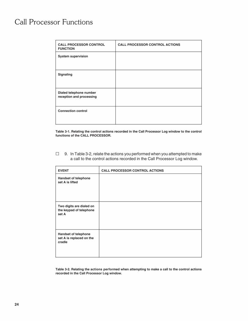
� 8. In Table 3-1, classify the control actions recorded in the Call Processor Logwindow according to the control function of the CALL PROCESSOR whichthey are related to.
� "��������!��������
24
CALL PROCESSOR CONTROLFUNCTION
CALL PROCESSOR CONTROL ACTIONS
System supervision
Signaling
Dialed telephone numberreception and processing
Connection control
Table 3-1. Relating the control actions recorded in the Call Processor Log window to the controlfunctions of the CALL PROCESSOR.
� 9. In Table 3-2, relate the actions you performed when you attempted to makea call to the control actions recorded in the Call Processor Log window.
EVENT CALL PROCESSOR CONTROL ACTIONS
Handset of telephoneset A is lifted
Two digits are dialed onthe keypad of telephoneset A
Handset of telephoneset A is replaced on thecradle
Table 3-2. Relating the actions performed when attempting to make a call to the control actionsrecorded in the Call Processor Log window.

� "��������!��������
25
� 10. In the control action named Service Request, what is the meaning of thefollowing detailed information: received from HS0, 01 ? Explain.
� 11. In the control action named Service Request, what is the meaning of thefollowing detailed information: mark ALI HS0, 01 as busy?
� 12. What is the purpose of the control action named Call Progress ToneTransmit Path Setup?
� 13. Explain why the control action named Call Progress Tone Removal is notimmediately followed by the control action named Call Progress ToneTransmit Path Release.
Step-By-Step Observation
� 14. In the LVTTS window, adjust the view so as to be able to see the circuitryof both ANALOG LINE INTERFACEs, the SWITCHING CIRCUIT, theSIGNALING CIRCUIT, and the CALL PROCESSOR.
Using the playback function of the Call Processor Log, make a step-by-stepobservation of what happened in the Central Office for each of the controlactions recorded in the log.
Note: The Previous View function of LVTTS allows you toreobtain the initial general view after you have zoomed on aparticular section.

� "��������!��������
26
From your observations, were several resources of the Central Officerequired to process the call, even if the call was not completed? Explain.
� 15. On the host computer, close the Telephony Training System software.
Turn off the TTS Power Supply, as well as the host computer (if it is nolonger required).
Disconnect the AC/DC power converters from the TTS Power Supply andthe analog telephone sets.
Disconnect the analog telephone sets from the Dual Analog Line Interface.
Remove the Dual Analog Line Interface from the Reconfigurable TrainingModule.
CONCLUSION
In this exercise, you became familiar with the call processor functions: systemsupervision, signaling, dialed telephone number reception and processing, andconnection control. You learned that, in order to perform these control functions, thecall processor must communicate with the analog line interfaces, as well as thesignaling and switching circuits of the central office.
You learned that the Telephony Training System has a useful function that canprovide a chronological record, or log, of all the control actions performed by theCALL PROCESSOR as it processes a call. You used this function to obtain a logof the control actions performed by the CALL PROCESSOR when a call is initiatedwithout being completed. You related each control action recorded in the log to aspecific control function of the CALL PROCESSOR. Finally, you made a step-by-step observation of what happened in the Central Office for each control actionrecorded in the log. This allowed you to see that, whenever a call is attempted bya subscriber, several resources of the Central Office are required to process the calleven when the call is not completed.
REVIEW QUESTIONS
1. How does the CALL PROCESSOR of the Telephony Training System supervisethe status of the telephone circuits?

� "��������!��������
27
2. How does the CALL PROCESSOR of the Telephony Training System performtelephone number detection and processing?
3. How does the CALL PROCESSOR of the Telephony Training System performthe signaling function?
4. How does the CALL PROCESSOR of the Telephony Training System performconnection control?
5. What is the purpose of the log function of the CALL PROCESSOR of theTelephony Training System?

28

��� ���������
������������
"��#����������
$�����������%"�$&'


31
������ �����
����������������� �!�������"#
EXERCISE OBJECTIVE
When you have completed this exercise, you will be familiar with the architecture ofa digital PABX (the Lab-Volt PABX). You will be able to highlight majorresemblances and differences between the architecture of a digital PABX and thatof a central office. You will also be able to demonstrate how two telephone sets areinterconnected in the Lab-Volt PABX.
DISCUSSION
Block Diagram of the Lab-Volt PABX
Today's PABX's are all-digital integrated systems as mentioned in the Unit'sDiscussion of Fundamentals, and the Lab-Volt PABX is no exception. It iscompletely digital inside, except for some analog circuitry mainly located in the trunkinterface and the trunk service circuit, and uses digital telephone sets of the ISDNtype. A simplified block diagram of the Lab-Volt PABX is shown in Figure 1-4.
Like any other PABX, the Lab-Volt PABX consists of the same basic elements asa central office, that is, line interfaces for the telephone sets, a switching circuit, asignaling circuit, a call processor, and a trunk interface. Each of these elements hasthe same function as in a central office. However, the implementation of certainelements differs from that used in a central office (like the Lab-Volt Central Officefor example), mainly because the telephone sets changed from analog to digitaltechnology. For instance, in the signaling circuit the DIGITAL SIGNALINGPROCESSOR and the CALL PROGRESS TONE GENERATOR replace the servicecircuits for analog line interfaces. The switching circuit still consists of a SPACE-DIVISION SWITCH but a device called a DIGITAL CONFERENCE BRIDGE isadded to allow conference calling. And obviously, the analog line interfaces arereplaced with digital line interfaces.
The Lab-Volt PABX also has an additional basic element, called ANNOUNCEMENTCIRCUIT, which is not found in a central office. The ANNOUNCEMENT CIRCUITallows intercom calls to be performed using any of the digital telephone setsconnected to the Lab-Volt PABX. Intercom calling is discussed in detail in the nextunit of this manual.

��������������(���� "�$&
32
LAB-VOLT PABX
DIGITALLINE
INTERFACE
0
1 2
7
*
8
4 5
* 0
1 2
7 8
4 5
#
3
9
6
#
3
9
6
TELEPHONESETS
1 2
4 5
*
7
0
8
4 5
* 0
7 8
1 2
3
6
#
9
6
#
9
3
CALL PROCESSOR
A
DUAL
TX0
RX0
D0TX
D0RX
D1RX
D1TX
RX1
TX1
LINEINTERFACE
DIGITALDUAL
B
LINEINTERFACES
RX3
RX2
RX1
RX0
DIVISIONSWITCH
SPACE-
SWITCHING CIRCUIT
TX0
TX1
TX2
TX3
RX5
RX4
TX5
TX4
BRIDGECONFERENCE
DIGITAL
RX5
RX4TX4
TX5
D1RX
PROCESSORSIGNALING
DIGITALD0RX
D1TX
D0TX
CIRCUITSERVICE
ANALOGTRUNK
RX3
TX3
CALLPROGRESS
TONETX3
STORAGEAND
TRUNK STATUSDEMULTIPLEXING TS2
GENERATOR CIRCUIT
SIGNALING CIRCUIT
INTERFACETS2
TX2
RX2
TRUNKANALOG
TRUNKINTERFACE
ANNOUNCEMENTCIRCUIT
RX3
SPEAKERSINTERCOM
TO AND
COFROM
Figure 1-4. Simplified block diagram of the Lab-Volt PABX.
The DUAL DIGITAL LINE INTERFACE
Figure 1-5 shows the block diagram of the digital line interfaces used in the Lab-VoltPABX. This block diagram is totally different from that of the analog line interfacesused in the Lab-Volt Central Office. In fact, the only elements that remain are theTXn and RXn terminals that allow the digital line interface to be connected to theSPACE-DIVISION SWITCH, and the time-slot assignment circuit (TSAC) thatgenerates the control signals used to multiplex and demultiplex the digitized voicesignals (PCM signals on the TXn and RXn lines). As the analog line interfaces incentral offices, the digital line interfaces in the Lab-Volt PABX are grouped in banks.

��������������(���� "�$&
33
TELEPHONESETS
1 2
4 5
*
7
0
8
4 5
* 0
7 8
1 2
3
6
#
9
6
#
9
3
DUAL DIGITAL LINE INTERFACE
E
RX
TX
(NRZ/ASI)CODER
LINE
B2
MUX
B1
D
RX
TX
(ASI/NRZ)DECODER
LINE
D
DEMUX B2
B1
B2 RXE
B1 RXE
B2 TXE
TSAC
B1 TXE
S/P
S/P
B2 RXE
B1 RXE
RXn
DnRX
2
8
8
P/S
P/S
B2 TXE
B1 TXE
DnTX
TXn
8
8
2
2
SWITCHOF SPACE-DIVISION
TO A TX INPUT
TO DIGITALSIGNALING
PROCESSOR
FROM AN RX OUTPUTOF SPACE-DIVISION
SWITCH
PROCESSORSIGNALING
FROM DIGITAL
FROM CALLPROCESSOR
DIGITAL
IRX
ITX
2
Figure 1-5. Block diagram of the DUAL DIGITAL LINE INTERFACE of the Lab-Volt PABX.
Each digital line interface is of the ISDN-BRI type and allows connection of twodigital telephone sets to the Lab-Volt PABX. This is why each digital line interfacein the Lab-Volt PABX is called a DUAL DIGITAL LINE INTERFACE.
Note: Those who are not familiar with the Integrated Services DigitalNetwork (ISDN) can refer to Appendix B of this manual which providesinformation on ISDN that is relevant to the Lab-Volt PABX.
For each direction of transmission (from the digital telephone sets to the PABX andvice versa), each DUAL DIGITAL LINE INTERFACE provides two bearer channels(labeled B1 and B2), each having a 64-kb/s transmission rate, and a data channel(labeled D) having a transmission rate of 16 kb/s. Each bearer channel, orB channel, is used to transmit a digitized voice signal (voice data) while theD channel is used to transmit signaling data. This explains why each DUALDIGITAL LINE INTERFACE can accommodate two digital telephone sets. Up to

��������������(���� "�$&
34
S/P
DEMUX
MUX
DUAL DIGITAL LINE INTERFACE
(NRZ/ASI)
LINECODER
DECODER(ASI/NRZ)
LINE
B2
B1
D
E
S/P
B2
D
B1
P/S
P/S
RXn
TXn
TELEPHONESETS
DIGITAL
DATAIRX
RECEIVED
FORMATISDN LAYER-1
B1 B2 D
SIGNALING DATA
VOICE DATA
VOICE DATA
ITX
SIGNALINGPROCESSOR
DIGITAL
PROCESSORCALL
VOICE DATA FROM CHANNEL B1
VOICE DATA FROM CHANNEL B2
SIGNALING DATA IN ISDNLAYER-2 FORMAT
LAYER-3 FORMATSIGNALING DATA IN ISDN
54 6 7 8
TIME SLOTS
VOICE DATA TOSPACE-DIVISION
SWITCH
four digital telephone sets can be connected to the Lab-Volt PABX because twoDUAL DIGITAL LINE INTERFACEs are available.
All data from the two digital telephone sets connected to a DUAL DIGITAL LINEINTERFACE (referred to as the ISDN layer-1 data) is time multiplexed to theB channels and the D channel. This data, which is coded using the alternate spaceinversion (ASI) line code, is received via the IRX terminal of the DUAL DIGITALLINE INTERFACE. Figure 1-6 illustrates the paths through which the voice data andsignaling data received at the IRX terminal are routed to the SPACE-DIVISIONSWITCH and the DIGITAL SIGNALING PROCESSOR of the PABX, respectively.
Figure 1-6. Paths through which the voice data and signaling data are routed to the SPACE-DIVISION SWITCH and the DIGITAL SIGNALING PROCESSOR of the PABX, respectively.
At the IRX terminal of the DUAL DIGITAL LINE INTERFACE, a line decoderconverts the received ASI-coded data to non return-to-zero (NRZ) coded data. Ademultiplexer (DEMUX) then separates (demultiplexes) the voice data and thesignaling data from the B channels and the D channel. Voice data is available at theB1 and B2 outputs of the DEMUX while the signaling data is available at theD output. Two parallel-to-serial (P/S) converters and their respective tri-state buffermultiplex the recovered voice data to two different time slots (which are determinedby the CALL PROCESSOR according to the connection to be established) fortransmission to the SPACE-DIVISION SWITCH via the TX line associated with theDUAL DIGITAL LINE INTERFACE. The signaling data recovered at the D outputof the DEMUX is sent to the DIGITAL SIGNALING PROCESSOR. Note that thisdata is coded according to the layer-2 format of the ISDN signaling protocol.

��������������(���� "�$&
35
DUAL DIGITAL LINE INTERFACE
SIGNALING DATA IN ISDN
D
FORMATISDN LAYER-1
TRANSMITTED
TELEPHONE
ITXDATA
SETS
DIGITAL
B1 B2
(NRZ/ASI)CODER
LINE
SIGNALING DATA
VOICE DATA
VOICE DATA
B2
B1
MUX
D
E
IRXDECODER
LINE
(ASI/NRZ)
DEMUX
D
B2
B1
PROCESSOR
VOICE DATA TO CHANNEL B1
VOICE DATA TO CHANNEL B2
S/P
LAYER-2 FORMAT
RXn
SIGNALINGDIGITAL
SWITCH
PROCESSOR
VOICE DATA FROM
TIME SLOTS
SPACE-DIVISION
4 5 6 7 8
CALL
LAYER-3 FORMATSIGNALING DATA IN ISDNP/S
P/STXn
S/P
Note: Variable transmit (TX) time slots are used in the Lab-Volt PABX (exceptfor the transmission of call progress tones) to minimize the chances of havinga telephone call blocked because no path is available to establish the requiredconnection. The TX time slots are dynamically assigned by the PABX callprocessor according to the connections to be established. This differs from theLab-Volt CO which uses fixed TX time slots, configured through dialog boxes,in order to facilitate the study of its operation.
In the other direction of transmission (from the PABX to the digital telephone sets),the PABX uses either one of the B channels of the interface to transmit voice datato a telephone set and the D channel to transmit signaling data to the two telephonesets. In other words, all data is time multiplexed to the B channels and theD channel to form an ISDN layer-1 data string that is transmitted to the two digitaltelephone sets via the ITX terminal of the DUAL DIGITAL LINE INTERFACE.Figure 1-7 illustrates the paths through which voice data from the SPACE-DIVISIONSWITCH and signaling data from the DIGITAL SIGNALING PROCESSOR arerouted to digital telephone sets.
Figure 1-7. Paths through which voice data from the SPACE-DIVISION SWITCH and signaling datafrom the DIGITAL SIGNALING PROCESSOR are routed to digital telephone sets.
In brief, voice data to be transmitted to the digital telephone sets is received throughthe RX line associated with the DUAL DIGITAL LINE INTERFACE. Two serial-to-parallel (S/P) converters and their respective tri-state buffer demultiplex voice data

��������������(���� "�$&
36
DUAL DIGITAL LINE INTERFACE
SIGNALING DATA IN ISDN
D
FORMATISDN LAYER-1
TELEPHONE
ITX
SETS
DIGITAL
B1 B2
(NRZ/ASI)CODER
LINE
B2
B1
MUX
D
E
IRXDECODER
LINE
(ASI/NRZ)
DEMUX
D
B2
B1
PROCESSOR
S/P
LAYER-2 FORMAT
RXn
SIGNALINGDIGITAL
PROCESSORCALL
P/S
P/STXn
S/P
FORMATISDN LAYER-1
B2B1 D
WITH DATA INCHANNELS B1, B2, AND D
ECHO BITS INTERLEAVED
from two different time slots (which are determined by the CALL PROCESSORaccording to the connection to be established). The two demultiplexed digitizedvoice signals are sent to inputs B1 and B2 of a multiplexer (MUX). The signalingdata from the DIGITAL SIGNALING PROCESSOR is available at the D input of themultiplexer. The multiplexer combines all data available on its various inputs into asingle data string, that is, the voice data at inputs B1 and B2 are multiplexed tochannels B1 and B2, respectively, and the signaling data at the D input ismultiplexed to the D channel. A line coder converts the data string from the NRZformat to the ASI format to obtain ISDN layer-1 data that is transmitted to the digitaltelephone sets.
Note that the signaling data received from the digital telephone sets connected toa DUAL DIGITAL LINE INTERFACE (data recovered at the D output of theDEMUX) is routed to the echo (E) input of the MUX as shown in Figure 1-8. Thisallows the signaling data to be echoed back to the digital telephone sets viaecho (E) bits that are interleaved with the data in the B and D channels of the ISDNlayer-1 data. This provides a means to resolve D channel contention. Additionalexplanation about D channel contention is provided in Appendix B of this manual.
Figure 1-8. Signaling data is echoed back to the digital telephone sets as a means of resolvingD channel contention.
As in the analog line interfaces of the Lab-Volt Central Office, a TSAC receives datafrom the call processor to generate pulse signals that are used to multiplex anddemultiplex digitized voice signals (PCM signals on the TXn and RXn lines).However, in the Lab-Volt PABX, each TSAC provides two transmit enable (TXE)signals and two receive enable (RXE) signals (see Figure 1-5) because each DUAL

��������������(���� "�$&
37
2 3 4 5 6 7 8 9 10 11 12 13TIME SLOTS
B1 TXESIGNAL
B2 TXESIGNAL
B1 RXESIGNAL
B2 RXESIGNAL
TIME
TIME
TIME
TIME
DIGITAL LINE INTERFACE accommodates two digital telephone sets. The B1 TXEand B2 TXE signals determine the time slots in which voice data from channels B1and B2 (voice data at the B1 and B2 outputs of the DEMUX), respectively, ismultiplexed to the TX line of the line interface. Similarly, the B1 RXE and B2 RXEsignals indicate the time slots during which voice data is to be read from the RX linefor redirection to channels B1 and B2 (inputs B1 and B2 of the MUX), respectively.Figure 1-9 shows an example of the TSAC output signals when voice data receivedfrom channels B1 and B2 is to be multiplexed to the TX line during time slots 5 and8, respectively, and voice data to be transmitted to the telephone sets viachannels B1 and B2 is to be read from the RX line during time slots 6 and 7,respectively.
Figure 1-9. Example of TSAC output signals used to multiplex and demultiplex digitized voicesignals (PCM signals on the TXn and RXn lines).
The Switching Circuit
The SPACE-DIVISION SWITCH in the switching circuit operates in the samemanner as the switch in the Lab-Volt Central Office. In brief, the SPACE-DIVISIONSWITCH performs space connections (connections of an input [TX] line to anyoutput [RX] line), at every time slot.
The switching circuit in the Lab-Volt PABX has an additional device called DIGITALCONFERENCE BRIDGE. This device can combine two digitized voice signals intoa single digitized signal. It is used to implement conference calling, which is studiedin the next unit of this manual.

��������������(���� "�$&
38
The Signaling Circuit
The signaling circuit in the Lab-Volt PABX consists of the DIGITAL SIGNALINGPROCESSOR, the CALL PROGRESS TONE GENERATOR, the ANALOG TRUNKSERVICE CIRCUIT, and the TRUNK STATUS DEMULTIPLEXING ANDSTORAGE CIRCUIT (see Figure 1-4).
The DIGITAL SIGNALING PROCESSOR is somewhat the equivalent of the servicecircuits for analog line interfaces used in the Lab-Volt Central Office, that is, it actsas a kind of interpret circuit. The DIGITAL SIGNALING PROCESSOR converts thesignaling data coming from the telephone sets (data in the D channel), which is inthe ISDN layer-2 format, to ISDN layer-3 signaling data. This data is thentransferred to the CALL PROCESSOR. Conversely, the DIGITAL SIGNALINGPROCESSOR converts signaling data from the CALL PROCESSOR, which is in theISDN layer-3 format, to ISDN layer-2 signaling data that is transmitted to thetelephone sets via the DUAL DIGITAL LINE INTERFACE. The exchange ofsignaling data between the digital telephone sets and the PABX will be studiedthoroughly in other exercises of this manual.
Although digital signaling is used in the Lab-Volt PABX, call progress tones are stillrequired to keep telephone users aware of call progression. The call progress tonesare provided by the Lab-Volt PABX because the digital telephone sets used with thisPABX do not produce these tones internally. The CALL PROGRESS TONEGENERATOR in the signaling circuit of the Lab-Volt PABX produces different digitalcall progress tones (dial tone, busy tone, etc.). These digital call progress tones arepermanently available on line TX3, each tone being multiplexed to a different timeslot. Any one of the digital call progress tones can be routed to a digital telephoneset via the SPACE-DIVISION SWITCH and one of the B channels of thecorresponding DUAL DIGITAL LINE INTERFACE. The operation of the CALLPROGRESS TONE GENERATOR as well as the routing of call progress tones todigital telephone sets is studied in detail in another exercise of this unit.
The ANALOG TRUNK SERVICE CIRCUIT and the TRUNK STATUS DEMUL-TIPLEXING AND STORAGE CIRCUIT make the link between the ANALOGTRUNK INTERFACE and the CALL PROCESSOR. The operation of the ANALOGTRUNK SERVICE CIRCUIT and the TRUNK STATUS DEMULTIPLEXING ANDSTORAGE CIRCUIT is studied in another manual of the Lab-Volt TelephonyTraining System.
The Trunk Interface
The ANALOG TRUNK INTERFACE in the Lab-Volt PABX converts voice datareceived from the SPACE-DIVISION SWITCH into an analog voice signal that canbe transmitted on an analog trunk line. Conversely, it converts an analog voicesignal received from a trunk line into voice data that is routed to the SPACE-DIVISION SWITCH. The operation of the ANALOG TRUNK INTERFACE is studiedin another manual of the Lab-Volt Telephony Training System.

��������������(���� "�$&
39
Procedure Summary
In the first part of the exercise, you will set up a PABX with the Telephony TrainingSystem (TTS).
In the second part of the exercise, you will study the architecture of the Lab-VoltPABX. This will allow you to see the resemblances and differences between theLab-Volt PABX and the Lab-Volt Central Office.
In the third part of the exercise, you will lift off the handset of a digital telephone setand determine which B channel is assigned to this telephone set for voice datatransmission in the corresponding digital line interface of the Lab-Volt PABX.
In the last part of the exercise, you will determine how the Lab-Volt PABX routes thedigitized voice signal coming from a digital telephone set to another digital telephoneset.
Note: Before proceeding with the procedure below, it is stronglyrecommended that you go through Section 4 of the Telephony TrainingSystem User Guide (part number 32964-E0) all the way. This section, entitled"Familiarization with the Lab-Volt PABX", provides detailed information on howto set up the Lab-Volt PABX, use its essential features, and ensure that thedigital telephone sets connected to it are set up to operate properly.
EQUIPMENT REQUIRED
Refer to Appendix A of this manual to obtain the list of equipment required toperform this exercise.
PROCEDURE
Setting Up the Lab-Volt PABX
� 1. Make sure that the Reconfigurable Training Module, Model 9431, isconnected to the TTS Power Supply, Model 9408.
Make sure that there is a network connection between the ReconfigurableTraining Module and the host computer.
Install the Digital Telephone Interface, Model 9476, into the digital (D) slotor one of the two analog/digital (A/D) slots of the Reconfigurable TrainingModule.
Connect two digital (ISDN) telephone sets provided with the Lab-Volt PABXto the left and right connectors of interface A of the Digital TelephoneInterface. These telephone sets will be referred to as digital telephonesets A-left (AL) and A-right (AR), respectively, throughout the exercise.

��������������(���� "�$&
40
CAUTION!
Do not connect or disconnect the digital telephone setswhen the Reconfigurable Training Module is turned on. Highvoltages are present on the RJ-45 connectors of the DigitalTelephone Interface.
� 2. Turn on the host computer.
Turn on the TTS Power Supply, then the Reconfigurable Training Module.
� 3. On the host computer, start the Telephony Training System software, thendownload the PABX program to the Reconfigurable Training Module. ThePABX program configures the Reconfigurable Training Module so that itoperates as a private automatic branch exchange (PABX).
Note: If the host computer is unable to download thePABX program to the Reconfigurable Training Module, it maynot be using the proper IP address. Have your instructor checkif the computer is using the proper IP address to communicatewith the Reconfigurable Training Module.
� 4. Lift off the handset of each digital telephone set connected to the Lab-VoltPABX, while observing the Lab-Volt PABX diagram in the LVTTS softwarewindow. When the handset of a digital telephone set is lifted off, an iconrepresenting this telephone set should appear connected to thecorresponding DUAL DIGITAL LINE INTERFACE in the Lab-Volt PABXdiagram. If so, this indicates that this telephone set is properly programmedto be operational with the Lab-Volt PABX. Otherwise, this means that thistelephone set is not properly programmed to be operational with theLab-Volt PABX.
Note: An icon representing the digital telephone set mayalready be displayed in the Lab-Volt PABX diagram before youlift off the handset of this telephone set. This occurs becauseeach digital telephone set automatically begins communicationwith the Lab-Volt PABX a certain time after it is powered up inorder to identify itself to the Lab-Volt PABX. This indicates thatthis digital telephone set is properly programmed to beoperational with the Lab-Volt PABX.
If a digital telephone set does not seem to be properly programmed, referto Section 4 of the Telephony Training System User Guide (part number32964-E0), entitled "Familiarization with the Lab-Volt PABX", to know howto properly program the digital telephone sets connected to the Lab-VoltPABX.
Hang up the handset of each digital telephone set.

��������������(���� "�$&
41
Basic Elements of the Lab-Volt PABX
� 5. On the host computer, examine the block diagram of the Lab-Volt PABXwithout zooming in on it. Notice that the Lab-Volt PABX contains the samebasic elements as the Lab-Volt Central Office, which are:
– line interfaces for the telephone sets;– a switching circuit;– a signaling circuit;– a call processor;– a trunk interface.
On the other hand, notice that the Lab-Volt PABX additionally contains anANNOUNCEMENT CIRCUIT, which is not found in the Lab-Volt CentralOffice.
� 6. On the host computer, zoom in on the icons representing digital telephonesets AL and AR. Using the Pan command, observe that each digitaltelephone set is connected to DUAL DIGITAL LINE INTERFACE A(DDLI A) of the Lab-Volt PABX, through two pairs of wires:
– one pair for transmission of the ISDN layer-1 data coming from thetelephone set to the interface via one of the interface IRX terminals;
– one pair for reception of the ISDN layer-1 data coming from theinterface via one of the interface ITX terminals.
� 7. Pan across DDLI A to examine its contents. Notice that the contents of thisinterface differs markedly from that of the analog line interfaces used in theLab-Volt Central Office. The only elements that remain are
– the TX0 and RX0 lines that connect DDLI A to the SPACE-DIVISIONSWITCH of the Lab-Volt PABX;
– the TSAC.
What are the TX0 and RX0 lines used for? What is the function of theTSAC?
� 8. Observe that, in addition to line TX0, DDLI A uses another transmit line,D0TX. This line permits the routing of the signaling data coming from digitaltelephone sets AL and AR (data recovered at the D output of the demul-tiplexer of DDLI A) to the DIGITAL SIGNALING PROCESSOR of theLab-Volt PABX. The data on line D0TX is in ISDN layer-2 data format.

��������������(���� "�$&
42
Also, observe that, in addition to line RX0, DDLI A uses another receiveline, D0RX. This line permits the routing of the signaling data coming fromthe DIGITAL SIGNALING PROCESSOR to digital telephone sets AL andAR, via the D input of the multiplexer of DDLI A. The data on line D0RX isin ISDN layer-2 data format.
� 9. Go to DUAL DIGITAL LINE INTERFACE B (DDLI B) and observe that itdoes not use the same transmit and receive lines as DDLI A. What doesthis imply?
Which lines are used by DDLI B to transmit and receive multiplexeddigitized voice signals respectively?
Which lines are used by DDLI B to transmit and receive signaling data toand from the DIGITAL SIGNALING PROCESSOR?
� 10. Go to the SWITCHING CIRCUIT of the Lab-Volt PABX. Observe that thiscircuit contains a TIME-SLOT SELECTOR and a SPACE-DIVISIONSWITCH used to perform space connections, as in the case of theSWITCHING CIRCUIT of the Lab-Volt Central Office.
Does the SPACE-DIVISION SWITCH of the Lab-Volt PABX has moreinputs and outputs than that of the Lab-Volt Central Office?
� Yes � No
Observe that an additional device called DIGITAL CONFERENCE BRIDGEis included in the SWITCHING CIRCUIT of the Lab-Volt PABX. What is theuse of this bridge?
��������������(���� "�$&
43
Through which transmit (TX) and receive (RX) lines are the SPACE-DIVISION SWITCH and DIGITAL CONFERENCE BRIDGEinterconnected?
� 11. Go to the SIGNALING CIRCUIT of the Lab-Volt PABX and examine itscontents. Observe that a DIGITAL SIGNALING PROCESSOR and a CALLPROGRESS TONE GENERATOR replace the service circuits for analogline interfaces and the hook status demultiplexing and storage circuit usedin the SIGNALING CIRCUIT of the Lab-Volt Central Office.
Which two other elements of the SIGNALING CIRCUIT of the Lab-VoltPABX (possibly appearing faded to show that they are not currentlyavailable in your Lab-Volt PABX) are not included in the SIGNALINGCIRCUIT of the Lab-Volt Central Office?
� 12. Examine the DIGITAL SIGNALING PROCESSOR of the SIGNALINGCIRCUIT. This device converts the signaling data coming from the digitaltelephone sets via the DDLI's, which is in ISDN layer-2 data format, toISDN layer-3 data format. Conversely, it converts the signaling data comingfrom the CALL PROCESSOR, which is in ISDN layer-3 data format, toISDN layer-2 data format. This data is then transmitted to the digitaltelephone sets via the digital line interfaces.
Through which lines does the DIGITAL SIGNALING PROCESSOR receivethe signaling data from the digital telephone sets?
Through which lines does the DIGITAL SIGNALING PROCESSORtransmit the signaling data from the CALL PROCESSOR to the digitaltelephone sets?
� 13. Examine the CALL PROGRESS TONE GENERATOR in the SIGNALINGCIRCUIT. Observe that it consists of four tone generators associated withfour CODEC's, and a TSAC that generates the control signals used tomultiplex each digital call progress tone to a different time slot on line TX3.

��������������(���� "�$&
44
Any one of the digital call progress tones present on line TX3 can be routedto a digital telephone set, via the SPACE-DIVISION SWITCH and one ofthe B channels of the corresponding digital line interface.
What are the four call progress tones generated by the CALL PROGRESSTONE GENERATOR?
� 14. Go to the ANNOUNCEMENT CIRCUIT of the Lab-Volt PABX. This circuitis used for implementation of intercom calling. It converts the digitized voicesignal coming from the intercom user's telephone set, via the SPACE-DIVISION SWITCH and one of the B channels of the corresponding digitalline interface, into an analog voice signal. This signal is amplified and thenrouted to intercom speakers.
Through which line is the ANNOUNCEMENT CIRCUIT connected to theSPACE-DIVISION SWITCH?
Assignment of a B Channel to a Digital Telephone Set
� 15. Go to DDLI A and zoom in on its B-CHANNEL ASSIGNMENT display.While observing this display, lift off the handset of digital telephone set AL.
Notice that, as soon as the handset is lifted off, the SPID (Service ProfileIDentifier) of digital telephone set AL appears in the B1 field of the display,indicating that channel B1 of DDLI A is assigned to this telephone set forvoice data transmission. Is this your observation?
� Yes � No
� 16. Do not hang up. While observing the B-CHANNEL ASSIGNMENT displayof DDLI A, lift off the handset of digital telephone set AR.
Notice that, as soon as the handset is lifted off, the SPID of digitaltelephone set AR appears in the B2 field of the display, indicating thatchannel B2 of DDLI A is assigned to this telephone set for voice datatransmission. Is this your observation?
� Yes � No

��������������(���� "�$&
45
� 17. Hang up the handset of digital telephone set AL. Does this cause theB1 field of the B-CHANNEL ASSIGNMENT display of DDLI A to return to"----", indicating that channel B1 of this interface is now unused?
� Yes � No
� 18. Hang up the handset of digital telephone set AR. Does this cause theB2 field of the B-CHANNEL ASSIGNMENT display of DDLI A to return to"----", indicating that channel B2 of this interface is now unused?
� Yes � No
Routing of the Voice Data from a Digital Telephone Set to Another in theLab-Volt PABX
� 19. Connect Oscilloscope probes 1, 2, 3, and 4 to TP5 (channel B1 P/S Con-verter output), TP11 (TSAC B1 TXE output), TP7 (TX0 line), and TP16(FRAME SYNC. signal) of DDLI A, respectively.
� 20. Start the Oscilloscope.
Make the following settings on the Oscilloscope:
Channel 1Mode . . . . . . . . . . . . . . . . . . . . . . . . . . . . . . . . . . . . . . . NormalSensitivity . . . . . . . . . . . . . . . . . . . . . . . . . . . . . . . . . . . 5 V/divInput Coupling . . . . . . . . . . . . . . . . . . . . . . . . . . . . . . . . . . . DC
Channel 2Mode . . . . . . . . . . . . . . . . . . . . . . . . . . . . . . . . . . . . . . . NormalSensitivity . . . . . . . . . . . . . . . . . . . . . . . . . . . . . . . . . . . 5 V/divInput Coupling . . . . . . . . . . . . . . . . . . . . . . . . . . . . . . . . . . . DC
Channel 3Mode . . . . . . . . . . . . . . . . . . . . . . . . . . . . . . . . . . . . . . . NormalSensitivity . . . . . . . . . . . . . . . . . . . . . . . . . . . . . . . . . . . 5 V/divInput Coupling . . . . . . . . . . . . . . . . . . . . . . . . . . . . . . . . . . . DC
Channel 4Mode . . . . . . . . . . . . . . . . . . . . . . . . . . . . . . . . . . . . . . . NormalSensitivity . . . . . . . . . . . . . . . . . . . . . . . . . . . . . . . . . . . 5 V/divInput Coupling . . . . . . . . . . . . . . . . . . . . . . . . . . . . . . . . . . . DC
Time Base . . . . . . . . . . . . . . . . . . . . . . . . . . . . . . . . . . . . . 10 μs/divTrigger
Source . . . . . . . . . . . . . . . . . . . . . . . . . . . . . . . . . . . . . . . . Ch 4Level . . . . . . . . . . . . . . . . . . . . . . . . . . . . . . . . . . . . . . . . 1.0 VSlope . . . . . . . . . . . . . . . . . . . . . . . . . . . . . . . . . . . . Positive (+)
Display Refresh . . . . . . . . . . . . . . . . . . . . . . . . . . . . . . . ContinuousDisplay Mode . . . . . . . . . . . . . . . . . . . . . . . . . . . . . . . . . . . . Square

��������������(���� "�$&
46
� 21. Lift off the handset of digital telephone set AL and dial the terminal numberassociated with digital telephone set AR. Lift off the handset of digitaltelephone set AR to answer the call and establish a communication.
Note: The terminal number associated with each digitaltelephone set can be found in the Addressing Cross-ReferenceTable of the Lab-Volt PABX.
� 22. Observe that a PCM signal appears at TP5 (channel-B1 P/S Converteroutput) of DDLI A on the Oscilloscope screen, especially when talking intothe handset of digital telephone set AL. Does this confirm that channel B1of DDLI A is currently assigned to digital telephone set AL for voice datatransmission? Explain why.
� 23. According to the TIME SLOT NUMBER displays of DDLI A, which transmit(TX) time slot is currently assigned to channel B1 of DDLI A? Explain.
Note: Time slots 1 to 4 are reserved for transmission of the callprogress tones produced by the CALL PROGRESS TOMEGENERATOR. This will be discussed in detail in Exercise 1-4.
� 24. On the Oscilloscope screen, observe that a pulse occurs in the TSAC B1TXE output signal (TP11) during time slot 5. Explain why.
Note: The pulse in the FRAME SYNC. signal at TP16 is alignedwith time slot 0 of each frame.
� 25. Observe that the PCM signal at TP5 (channel B1 P/S Converter output) ofDDLI A appears in the signal at TP7 (TX0 line) of this interface during timeslot 5. Explain why.

��������������(���� "�$&
47
� 26. From the observations you have made up to this point, explain how thevoice data from a digital telephone set is routed to an input of the SPACE-DIVISION SWITCH of the SWITCHING CIRCUIT in the Lab-Volt PABX.
� 27. Go to the SWITCHING CIRCUIT of the Lab-Volt PABX. Using the TIME-SLOT SELECTOR of this circuit, observe the connections made by theSPACE-DIVISION SWITCH during time slot 5.
You should observe that during time slot 5, which is the TX time slotassigned to channel B1 of DDLI A, the SPACE-DIVISION SWITCHconnects line TX0 (DDLI-A transmit line) to line RX0 (DDLI-A receive line).What is the purpose of this connection?
� 28. Go to the B-CHANNEL ASSIGNMENT display of DDLI A. Which B channelof this interface is currently assigned to digital telephone set AR for voicedata transmission? Explain.
� 29. According to the TIME SLOT NUMBER displays of DDLI A, which receivetime slot is currently assigned to channel B2 of this interface?

��������������(���� "�$&
48
Does this time slot correspond to the transmit time slot assigned tochannel B1 of DDLI A? What does this imply?
� 30. Disconnect Oscilloscope probes 1 through 3.
Connect Oscilloscope probes 1, 2, and 3 to TP10 (RX0 line), TP14 (TSACB2 RXE output), and TP9 (channel-B2 S/P Converter input), respectively.
� 31. Does a pulse occur in the signal at TP14 (TSAC B2 RXE output) of DDLI Aduring time slot 5? Why?
� 32. Observe that a PCM signal appears at TP10 (RX0 line) of DDLI A,especially when talking into the handset of digital telephone set AL, due tothe TX0-to-RX0 connection made by the SPACE-DIVISION SWITCH of theSWITCHING CIRCUIT during time slot 5. Is this PCM signal routed to thechannel-B2 S/P Converter input (TP9) of DDLI A? Explain.
��������������(���� "�$&
49
� 33. From your observations, explain how the voice data from an output of theSPACE-DIVISION SWITCH is routed to a digital telephone set.
� 34. To summarize what you have learned in this exercise, explain how theCALL PROCESSOR in the Lab-Volt PABX established a connectionbetween the B channels assigned to digital telephone sets AL and AR inDDLI A to permit a normal (bidirectional) conversation between the usersat these telephone sets.
Note: In the preceding steps, you studied voice datatransmission in a single direction only, that is, from digitaltelephone set AL to digital telephone set AR. To answer theabove question, you can use LVTTS as you have done so far todetermine how voice data transmission occurs in the otherdirection, that is, from digital telephone set AR to digitaltelephone set AL.
– CALL PROCESSOR actions performed to establish a connection fortransmission of the voice data from digital telephone set AL to digitaltelephone set AR:

��������������(���� "�$&
50
– CALL PROCESSOR actions performed to establish a connection fortransmission of the voice data from digital telephone set AR to digitaltelephone set AL:
� 35. Compare the technique used to interconnect two line interfaces in theLab-Volt PABX to that used to in the Lab-Volt Central Office.
� 36. Hang up the handsets of digital telephone sets AR and AL.
� 37. On the host computer, close the Telephony Training System software.
Turn off the TTS Power Supply, as well as the host computer (if it is nolonger required).
Disconnect the digital telephone sets from the Digital Telephone Interface.
Remove the Digital Telephone Interface from the Reconfigurable TrainingModule.
CONCLUSION
In this exercise, you familiarized yourself with the architecture of the Lab-Volt PABX.You saw that, similar to the Lab-Volt Central Office, the Lab-Volt PABX is made upof line interfaces, a switching circuit, a signaling circuit, a call processor, and a trunkinterface. Unlike the Lab-Volt Central Office, however, the Lab-Volt PABX usesdigital line interfaces instead of analog line interfaces, its switching circuit includesa digital conference bridge to allow conference calling, its signaling circuit contains
��������������(���� "�$&
51
a digital signaling processor and a call progress tone generator in place of servicecircuits for analog line interfaces and a hook status demultiplexing and storagecircuit, and it includes an announcement circuit.
You learned that the digital line interfaces of the Lab-Volt PABX are of the ISDN-BRItype: for each direction of transmission (from the digital telephone sets to theLab-Volt PABX and vice versa), these interfaces provide two bearer channels,labeled B1 and B2, that are used to convey voice data, as well as a data channel,labeled D, that is used to convey signaling data. Because of this, each digital lineinterface can accommodate two digital telephone sets and is thus referred to as adual digital line interface (DDLI). You saw that, as soon as the handset of a digitaltelephone set is lifted off, the Lab-Volt PABX assigns a B channel to this telephoneset in the corresponding digital line interface. You learned that the voice dataproduced by a digital telephone set is time multiplexed to the assigned B channel,while the signaling data produced by this telephone set is time multiplexed to theD channel, all the data being sent in ISDN layer-1 data format to the correspondingdigital line interface in the Lab-Volt PABX. Conversely, you learned that the Lab-VoltPABX transmits voice data to a digital telephone set by time multiplexing this datato one of the B channels of the interface, and that it transmits signaling data to thistelephone set by time multiplexing this data to the D channel, all the data being sentto the telephone set in ISDN layer-1 data format.
Finally, you compared the technique used to interconnect two line interfaces in theLab-Volt PABX to that used in the Lab-Volt Central Office. You saw that, in bothcases, the line interfaces are interconnected by combining time-multiplexedswitching with space-division switching. The only difference lies in the way time-multiplexed switching is performed: in the Lab-Volt PABX, it is performed bydynamically assigning transmit and receive time slots to the line interfaces; in theLab-Volt Central Office, it is performed by dynamically assigning receive time slotsto the line interfaces, the transmit time slots being fixed and user-determinedthrough the use of dialog boxes.
REVIEW QUESTIONS
1. How do the architectures of the Lab-Volt PABX and Lab-Volt Central Officeresemble? How do they differ?

��������������(���� "�$&
52
2. Explain why each digital line interface on the Lab-Volt PABX can accommodatetwo digital telephone sets.
3. Describe the paths through which the voice data and the signaling data from adigital telephone set are routed to the SPACE-DIVISION SWITCH and theDIGITAL SIGNALING PROCESSOR of the Lab-Volt PABX.
4. How does the Lab-Volt PABX transmit voice data and signaling data to the twodigital telephone sets associated with a digital line interface?
5. What is the use of the Bn TXE and Bn RXE signals generated by the TSAC ofa digital line interface in the Lab-Volt PABX?

��� ���������
������������
"�$&�� �������


55
������ �����
�����!�����$���������
EXERCISE OBJECTIVE
When you have completed this exercise, you will know the role of the analog trunkinterface in a PABX. You will be able to explain the various functions of the analogtrunk interface. You will be familiar with the block diagram and operation of theanalog trunk interface in the Lab-Volt PABX.
DISCUSSION
Role of the Analog Trunk Interface
A PABX performs basic enterprise switching, that is, it makes the connectionsrequired to establish all calls between telephone sets located in an enterprise. APABX also concentrates all telephone sets in the enterprise to a limited number oftelephone lines that home in on the local CO. In many installations, conventional(analog) telephone lines, referred to as PABX analog trunks, are used to connecta PABX to the local CO.
Today's PABX's are all-digital integrated systems that switch digitized voice signalsand use digital signaling protocols. Because of the intrinsic nature of modernPABX's, some kind of hybrid circuitry is required to interface each analog trunk(telephone line) with the digital circuitry in a PABX. This is the role of the analogtrunk interfaces as shown in Figure 1-4. On one side, each analog trunk interfaceexchanges digital signals with the PABX circuitry. On the other side, it transmits andreceives analog signals via a PABX analog trunk. In other words, the role of theanalog trunk interface is to make the PABX, which is essentially a digital machine,appear as a conventional analog telephone set to the local CO. Note that oneanalog trunk interface is required for each PABX analog trunk. Also note that theanalog trunk interfaces in a PABX are usually grouped in banks as are the analogline interfaces in central offices.

�� �������)�������
56
ENTERPRISE PREMISES
SWITCHINGAND
SIGNALINGDIGITALLINE
INTERFACES
DIGITAL
EQUIPMENT
TRUNKINTERFACES
TELEPHONE LINESCONVENTIONAL
FROMTHE LOCALCENTRALOFFICE
TO AND
PABX
0
1 2
7
*
8
4 5
* 0
1 2
7 8
4 5
#
3
9
6
#
3
9
6
TELEPHONESETS
1 2
4 5
*
7
0
8
4 5
* 0
7 8
1 2
3
6
#
9
6
#
9
3
CALL PROCESSOR
DIGITAL
ANALOGBANK OF
TRUNKSPABX ANALOG
Figure 1-4. Analog trunk interfaces make a link between the digital circuitry in a modern PABX andanalog trunks.
Functions of the Analog Trunk Interface
To correctly link the digital circuitry in a PABX to the analog trunks and make thePABX appear as a conventional analog telephone set to the local CO, the analogtrunk interface performs the following functions:
1. Detects the ringing voltage applied across the analog trunk when there is anincoming call to the PABX;
2. Provides trunk status information (analog trunk loop open or closed) to allowthe PABX call processor to perform trunk supervision;
3. Closes the analog trunk loop to answer an incoming call to the PABX orinitiate an external call;
4. Converts time-division multiplexed serial digital signals (voice, DTMF dialingtones) from the PABX circuitry into analog signals that can be transmitted viathe analog trunk;

�� �������)�������
57
5. Converts analog signals (voice, call progress tones, caller identification data)received from the analog trunk into time-division multiplexed serial digitalsignals before they are routed to the PABX circuitry;
6. Performs two-wire to four-wire conversion because the analog trunk is a two-wire circuit whereas the PABX circuitry uses 4-wire circuits;
7. Opens the analog trunk loop to terminate an external call.
The remaining subsections of this discussion relate the above functions to the blockdiagram of the ANALOG TRUNK INTERFACE in the Lab-Volt PABX.
Block Diagram of the ANALOG TRUNK INTERFACE in the Lab-Volt PABX
Figure 1-5 is a block diagram of the ANALOG TRUNK INTERFACE in the Lab-VoltPABX. The tip (T) and ring (R) terminals of the ANALOG TRUNK INTERFACEconnect to the PABX analog trunk (local loop going to the Lab-Volt CO). Analogsignals (voice signals, call progress tones, and DTMF dialing tones) are exchangedvia these terminals. On the other side of the ANALOG TRUNK INTERFACE, thereceive (RX2), transmit (TX2), sampling clock, bit clock, trunk status (TKS2), anddata terminals connect to the call processor and the switching and signaling circuitsof the Lab-Volt PABX. These terminals carry digital signals (digitized voice signals,DTMF dialing tones, call progress tones, etc).
Operation of the ANALOG TRUNK INTERFACE in the Lab-Volt PABX
This subsection explains the operation of the ANALOG TRUNK INTERFACE in theLab-Volt PABX. Many of the explanations that follow are based on the blockdiagram shown in Figure 1-5. Furthermore, the subsection highlights the fact thatthe ANALOG TRUNK INTERFACE is somewhat a mixture of analog line interfacecircuitry (CODEC, TSAC, 2W/4W conversion circuit and loop current detector in asubscriber loop interface circuit) and analog telephone set circuitry (switchhook andringing voltage detector in an electronic ringer circuit).

�� �������)�������
58
ANALOG TRUNK INTERFACE
TIME-SLOTASSIGNMENT
(TSAC 1)CIRCUIT 1
(CODEC)DECODERENCODER/
DUPLEXERANSWERRELAY
RING ANDTRUNKSTATUS
DETECTOR
CALLERIDENTIFICATION
CIRCUIT 2ASSIGNMENT
TIME-SLOT
(TSAC 2)
ACCESS PATH
RECEIVE (RX2)
TRANSMIT (TX2)
SAMPLING CLOCK
BIT CLOCK
DATA
TRUNK STATUS (TKS2)
DATA TSTXE
PABXANALOGTRUNK
TIP (T)
RING (R)
LOCALFROM
TO AND
CO
FROMDIGITAL
SWITCHINGCIRCUITOF PABX
TO AND
FROMPABX
FROM CALLPROCESSOR
OF PABX
CIRCUITOF PABX
SIGNALINGTO
PROCESSOROF PABX
FROM CALL
TXE
RXE
ANS
Figure 1-5. Block diagram of the ANALOG TRUNK INTERFACE in the Lab-Volt PABX.
ANSWER RELAY
The ANSWER RELAY is a double-pole single-throw contact relay as shown inFigure 1-6. It plays a role similar to that of the switchhook in an analog telephoneset. When the PABX analog trunk is not in use, the relay contacts are open asshown in Figure 1-6 (a). During a call, the relay contacts are closed to connect theanalog trunk line to the DUPLEXER (via the RING AND TRUNK STATUSDETECTOR). This allows analog signals to go from the DUPLEXER to the analogtrunk and vice versa. Furthermore, this causes DC current to flow through the PABX

�� �������)�������
59
FROM ANS OUPUTOF TSAC 1
DUPLEXER
ANSWERRELAY
STATUSDETECTOR
TRUNKRING AND CENTRAL
OFFICE
CIRCUITFEED
BATTERYTIP (T)
RING (R)
PABX ANALOG TRUNK
DC CURRENT FLOWINGTHROUGH THE PABX ANALOGTRUNK LOOP
(b) ANSWER RELAY closed
COIL
ANALOG TRUNK INTERFACE
(a) ANSWER RELAY open
DETECTORSTATUSTRUNK
RING AND
DUPLEXER
COIL
FROM ANS OUPUTOF TSAC 1
ANALOG TRUNK INTERFACE
RELAYANSWER
TIP (T)
PABX ANALOG TRUNK
RING (R)
OFFICE
BATTERYFEED
CIRCUIT
CENTRAL
ANALOG LINEINTERFACE
ANALOG LINEINTERFACE
analog trunk loop as shown in Figure 1-6 (b). This is because the battery feed circuitof the analog line interface in the CO permanently applies DC voltage across the tipand ring wires of the analog trunk.
Figure 1-6. The ANSWER RELAY plays a role similar to that of the switchhook in an analogtelephone set.

�� �������)�������
60
The ANSWER RELAY is controlled by the PABX call processor via TIME-SLOTASSIGNMENT CIRCUIT 1 (TSAC 1) of the ANALOG TRUNK INTERFACE. Whenthe PABX call processor sends data to TSAC 1 that forces its ANS output to go tologic state 1, the ANSWER RELAY closes. In brief, the ANSWER RELAY, inconjunction with TSAC 1, performs functions 3 and 7 mentioned in the previoussubsection (i.e. closing the analog trunk loop to answer or initiate an external calland opening the analog trunk loop to terminate an external call).
RING AND TRUNK STATUS DETECTOR
The RING AND TRUNK STATUS DETECTOR performs the first two functions ofan analog trunk interface mentioned in the previous subsection: ringing voltagedetection and trunk status indication. When the ringing voltage is applied across thePABX analog trunk by the CO, it is detected by the RING AND TRUNK STATUSDETECTOR which sets its output to logic state 1. Similarly, when the ANSWERRELAY closes, DC current starts to flow in the analog trunk loop. This current isdetected by the RING AND TRUNK STATUS DETECTOR which sets its output tologic state 1. Note that all analog signals exchanged via the PABX analog trunkpass through the RING AND TRUNK STATUS DETECTOR without being modified.Also note that the functions performed by the RING AND TRUNK STATUSDETECTOR are basically the same as the AC ringing voltage detection in theelectronic ringer circuit of an analog telephone set and the loop current detection inthe subscriber loop interface circuit (SLIC) of an analog line interface.
DUPLEXER
The DUPLEXER performs function 6 mentioned in the previous subsection: two-wireto four-wire conversion. This function is equivalent to the hybrid function performedby the SLIC of each analog line interface in a CO. Figure 1-7 illustrates theoperation of the DUPLEXER.
The DUPLEXER converts the balanced signal received from the PABX analog trunk(via the ANSWER RELAY and the RING AND TRUNK STATUS DETECTOR) intoa single-ended analog signal, and routes this signal to the ENCODER/DECODER (CODEC) analog input. Conversely, the DUPLEXER receives a single-ended analog signal from the CODEC, and converts this signal into a balancedsignal to be transmitted via the PABX analog trunk. Furthermore, the DUPLEXERprevents the balanced signal to be transmitted from being returned to the CODECanalog input as a single-ended signal. This prevents the signal to be transmitted viathe PABX analog trunk from being echoed in the PABX.
Note: A single-ended signal is available on a single wire. However, the voltagerelated to such a signal is measured (or sensed) by connecting an instrument(or any other electronic device) between this wire and a wire connected to thecircuit's common terminal.

�� �������)�������
61
DUPLEXER
TO BE TRANSMITTEDVIA TRUNK
RECEIVEDANALOG SIGNAL
VIA TRUNKTRANSMITTED RECEIVED
FROM TRUNK
SIGNAL TO BE SIGNALENCODER/DECODER(CODEC)
BALANCEDBALANCED
+
TRUNK VIAANSWER RELAY
RING AND TRUNK
PABX ANALOG
STATUS DETECTOR
TO AND FROM
ANALOG SIGNAL
FROM TRUNK
SWITCHING
LAB-VOLTIN
CIRCUIT
TO AND FROM
PABX
Figure 1-7. Operation of the DUPLEXER in the ANALOG TRUNK INTERFACE.
ENCODER/DECODER and TIME-SLOT ASSIGNMENT CIRCUIT 1
The ENCODER/DECODER (CODEC) and TIME-SLOT ASSIGNMENT CIRCUIT 1(TSAC 1) perform functions 4 and 5 mentioned in the previous subsection. In factthese two functions are very similar to the coding function performed by the CODECand TSAC of each analog line interface in a CO.
In brief, the CODEC converts the analog signal received from the PABX analogtrunk, via the RING AND TRUNK STATUS DETECTOR, ANSWER RELAY, andDUPLEXER, into a digital signal. This signal consists of serial 8-bit PCM codesoccurring at a rate of 8000 codes/s. Each PCM code is then time-divisionmultiplexed to line TX2 which connects to the switching circuit of the PABX. TSAC 1receives data from the call processor that determines the time slot assigned to theCODEC to multiplex each PCM code to line TX2. TSAC 1 produces a rectangularpulse signal at its TXE output that is aligned with the assigned transmit (TX) timeslot. Figure 1-8 shows an example of the TSAC-1 TXE output signal when TX timeslot 5 is assigned to the CODEC.

�� �������)�������
62
2 3 4 5 6 7 8 9 10 11 12 13 14 15 16 17
TIME0
1
TIME SLOTS
TSAC 1TXE OUTPUT
SIGNAL
DIGITALSIGNAL
ON LINE TX2
TSAC 1RXE OUTPUT
SIGNAL
DIGITALSIGNAL
ON LINE RX2
0
1
TIME
0
1
TIME
8-BIT SERIAL PCM CODE
HIGH-IMPEDANCE STATE
0
1 HIGH-IMPEDANCE STATE
TIME
8-BIT SERIAL PCM CODE
Figure 1-8. Multiplexing and demultiplexing signals at the TXE and RXE outputs of TSAC 1.
In the opposite direction, the CODEC receives a digital signal, to be transmitted viathe PABX analog trunk, from line RX2 of the PABX switching circuit. This digitalsignal consists of time-division multiplexed serial 8-bit PCM codes occurring at arate of 8000 codes/s. The CODEC demultiplexes the digital signal received vialine RX2 and converts it into an analog signal that is transmitted via the PABXanalog trunk. TSAC 1 receives data from the call processor that determines the timeslot assigned to the CODEC to demultiplex a digital signal from line RX2. TSAC 1produces a rectangular pulse signal at its RXE output that is aligned with theassigned receive (RX) time slot. Figure 1-8 shows an example of the TSAC-1 RXEoutput signal when RX time slot 7 is assigned to the CODEC.
Note that both the TX and RX time slots of the CODEC in the ANALOG TRUNKINTERFACE are dynamically assigned by the PABX call processor according to theconnections to be established.
TIME-SLOT ASSIGNMENT CIRCUIT 2
The analog trunk interfaces in a PABX are usually grouped in banks as mentionedearlier in this discussion. The status of the analog trunk associated with eachinterface in a bank is generally time-division multiplexed so that complete statusinformation about all trunks in the bank can be routed to the signaling circuit of thePABX via a single transmission line. A fixed time slot is assigned to each analogtrunk interface for the transmission of the trunk status.
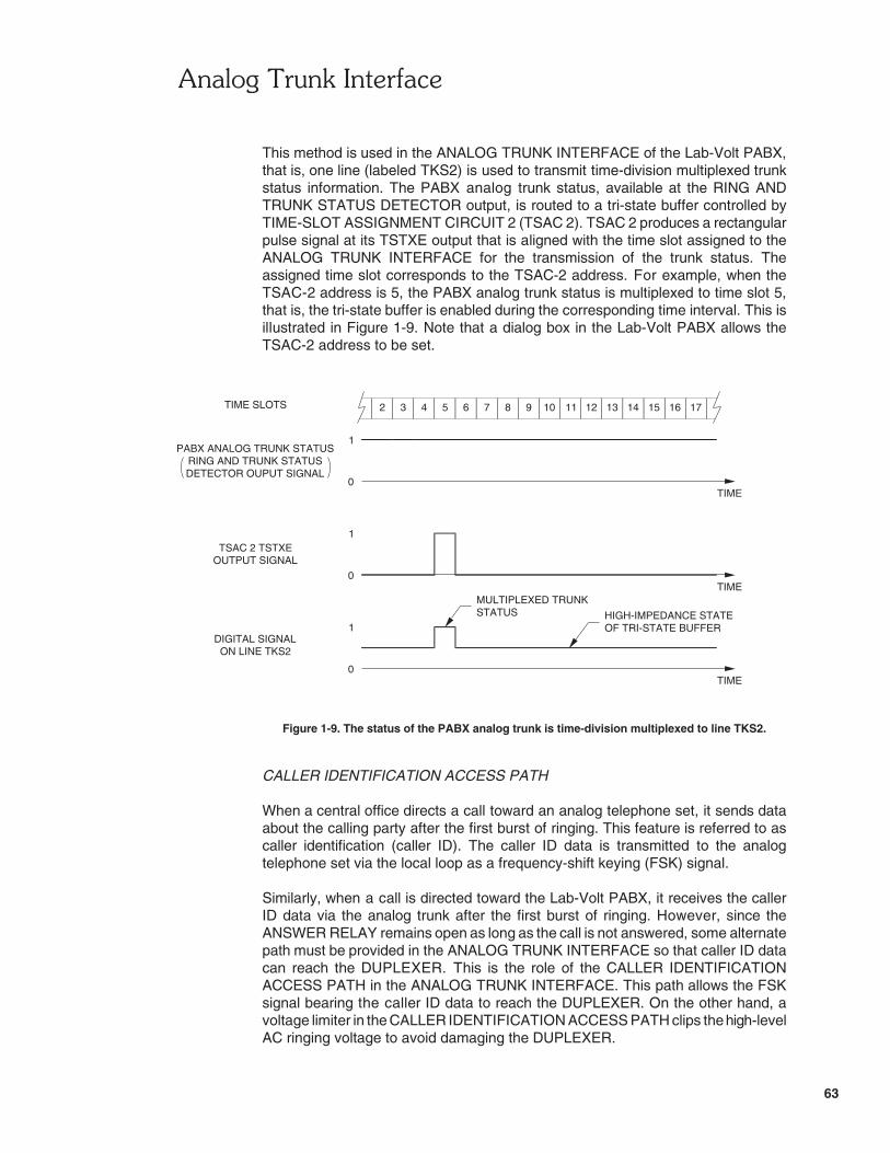
�� �������)�������
63
2 3 4 5 6 7 8 9 10 11 12 13 14 15 16 17
TIME0
1
TIME SLOTS
PABX ANALOG TRUNK STATUSRING AND TRUNK STATUSDETECTOR OUPUT SIGNAL
TSAC 2 TSTXEOUTPUT SIGNAL
0
1
TIMEMULTIPLEXED TRUNK
ON LINE TKS2
0
DIGITAL SIGNAL1
TIME
OF TRI-STATE BUFFERHIGH-IMPEDANCE STATESTATUS
This method is used in the ANALOG TRUNK INTERFACE of the Lab-Volt PABX,that is, one line (labeled TKS2) is used to transmit time-division multiplexed trunkstatus information. The PABX analog trunk status, available at the RING ANDTRUNK STATUS DETECTOR output, is routed to a tri-state buffer controlled byTIME-SLOT ASSIGNMENT CIRCUIT 2 (TSAC 2). TSAC 2 produces a rectangularpulse signal at its TSTXE output that is aligned with the time slot assigned to theANALOG TRUNK INTERFACE for the transmission of the trunk status. Theassigned time slot corresponds to the TSAC-2 address. For example, when theTSAC-2 address is 5, the PABX analog trunk status is multiplexed to time slot 5,that is, the tri-state buffer is enabled during the corresponding time interval. This isillustrated in Figure 1-9. Note that a dialog box in the Lab-Volt PABX allows theTSAC-2 address to be set.
Figure 1-9. The status of the PABX analog trunk is time-division multiplexed to line TKS2.
CALLER IDENTIFICATION ACCESS PATH
When a central office directs a call toward an analog telephone set, it sends dataabout the calling party after the first burst of ringing. This feature is referred to ascaller identification (caller ID). The caller ID data is transmitted to the analogtelephone set via the local loop as a frequency-shift keying (FSK) signal.
Similarly, when a call is directed toward the Lab-Volt PABX, it receives the callerID data via the analog trunk after the first burst of ringing. However, since theANSWER RELAY remains open as long as the call is not answered, some alternatepath must be provided in the ANALOG TRUNK INTERFACE so that caller ID datacan reach the DUPLEXER. This is the role of the CALLER IDENTIFICATIONACCESS PATH in the ANALOG TRUNK INTERFACE. This path allows the FSKsignal bearing the caller ID data to reach the DUPLEXER. On the other hand, avoltage limiter in the CALLER IDENTIFICATION ACCESS PATH clips the high-levelAC ringing voltage to avoid damaging the DUPLEXER.

�� �������)�������
64
Even though a voltage limiter in the CALLER IDENTIFICATION ACCESS PATHclips the high-level AC ringing voltage when the ANSWER RELAY is open, theDUPLEXER is provided with its own voltage limiter. This is because, when a call isanswered while the AC ringing voltage is applied across the analog trunk, theANSWER RELAY closes and the AC ringing voltage is applied directly to theDUPLEXER until the CO detects that the call is answered. This generally takesabout 100 ms for a CO to detect that a call is answered, and this should neverexceed 200 ms.
Procedure Summary
In the first part of the exercise, you will set up an analog trunk between a Lab-VoltPABX and a Lab-Volt Central Office.
In the second part of the exercise, you will study the operation of the ANSWERRELAY and RING AND TRUNK STATUS DETECTOR of the ANALOG TRUNKINTERFACE in the Lab-Volt PABX. To do so, you will observe the signals involvedin the operation of these components when receiving or making an external call.
In the third part of the exercise, you will study the operation of the DUPLEXER,CODEC, and TSAC 1 of the ANALOG TRUNK INTERFACE. To do so, you willobserve the input and output signals of these components during a call between adigital telephone set connected to the Lab-Volt PABX and an analog telephone setconnected to the Lab-Volt CO.
In the last part of the exercise, you will observe how the status of the analog trunkassociated with the ANALOG TRUNK INTERFACE is digitized and time-divisionmultiplexed to a trunk status line.
EQUIPMENT REQUIRED
Refer to Appendix A of this manual to obtain the list of equipment required toperform this exercise.
PROCEDURE
Setting Up an Analog Trunk Between a Lab-Volt PABX and a Lab-Volt CentralOffice
Note: In this exercise, it is assumed that a single host computer is usedto download the PABX and CO programs to two ReconfigurableTraining Modules, Model 9431. This host computer is used to monitorthe Lab-Volt PABX.
� 1. Make sure that two Reconfigurable Training Modules, Model 9431, areconnected to the TTS Power Supply, Model 9408.
Make sure that there is a network connection between each ReconfigurableTraining Module and the host computer.

�� �������)�������
65
Install the Dual Analog Line Interface, Model 9475, into one of the twoanalog/digital (A/D) slots of a Reconfigurable Training Module. This modulewill be used as a central office (CO). Connect an analog telephone set tothe Dual Analog Line Interface. Make sure that the tone dialing mode isselected on this telephone set.
CAUTION!
Do not connect or disconnect the analog telephone setwhen the Reconfigurable Training Module is turned on. Highvoltages are present on the standard telephone connectorsof the Dual Analog Line Interface.
Connect the AC/DC power converter supplied with the analog telephone setto one of the AC power outlets on the TTS Power Supply. Connect theDC power output jack of the AC/DC power converter to the DC power inputconnector on the analog telephone set.
� 2. Install the Digital Telephone Interface, Model 9476, into the digital (D) slotor one of the two analog/digital (A/D) slots of the other ReconfigurableTraining Module. This module will be used as a PABX. Connect two digital(ISDN) telephone sets provided with the Lab-Volt PABX to the left and rightconnectors of interface A of the Digital Telephone Interface. Thesetelephone sets will be referred to as digital telephone sets A-left (AL) andA-right (AR), respectively, throughout the exercise.
CAUTION!
Do not connect or disconnect the digital telephone setswhen the Reconfigurable Training Module is turned on. Highvoltages are present on the RJ-45 connectors of the DigitalTelephone Interface.
Finally, install the PABX Analog Trunk Interface, Model 9477, into one ofthe two analog/digital (A/D) slots of the Reconfigurable Training Moduleused as a PABX. Using the analog trunk line provided with the PABXAnalog Trunk Interface (two-wire cable terminated with standard [RJ-11]male telephone connectors), connect the RJ-11 female connector on thePABX Analog Trunk Interface installed in the Reconfigurable TrainingModule used as a PABX to the remaining RJ-11 female connector on theDual Analog Line Interface installed in the Reconfigurable Training Moduleused as a CO.
� 3. Turn on the host computer.
Turn on the TTS Power Supply, then turn on the Reconfigurable TrainingModules.

�� �������)�������
66
� 4. On the host computer, start the Telephony Training System software, thendownload the PABX program to the Reconfigurable Training Module usedas a PABX.
Note: If the host computer is unable to download thePABX program to the Reconfigurable Training Module used asa PABX, make sure that the proper IP address is used tocommunicate with this Reconfigurable Training Module.
� 5. Lift off the handset of each digital telephone set connected to the Lab-VoltPABX, while observing the Lab-Volt PABX diagram in the LVTTS softwarewindow. When the handset of a digital telephone set is lifted off, an iconrepresenting this telephone set should appear connected to thecorresponding DUAL DIGITAL LINE INTERFACE in the Lab-Volt PABXdiagram. If so, this indicates that this telephone set is properly programmedto be operational with the Lab-Volt PABX. Otherwise, this means that thistelephone set is not properly programmed to be operational with theLab-Volt PABX.
Note: An icon representing the digital telephone set mayalready be displayed in the Lab-Volt PABX diagram before youlift off the handset of this telephone set. This occurs becauseeach digital telephone set automatically begins communicationwith the Lab-Volt PABX a certain time after it is powered up inorder to identify itself to the Lab-Volt PABX. This indicates thatthis digital telephone set is properly programmed to beoperational with the Lab-Volt PABX.
If a digital telephone set does not seem to be properly programmed, referto Section 4 of the Telephony Training System User Guide (part number32964-E0), entitled "Familiarization with the Lab-Volt PABX", to know howto properly program the digital telephone sets connected to the Lab-VoltPABX.
Hang up the handset of each digital telephone set.
� 6. On the host computer, designate digital telephone set AL of the Lab-VoltPABX as the attendant's telephone set. Make sure that no external callrestriction is applied to digital telephone sets AL and AR. Set the DTMFdialing tone duration to 1 s.
� 7. On the host computer, download the CO program to the ReconfigurableTraining Module used as a CO.
Note: If the host computer is unable to download theCO program to the Reconfigurable Training Module used as aCO, make sure that the proper IP address is used tocommunicate with this Reconfigurable Training Module.

�� �������)�������
67
Once the CO program has been downloaded, a box representing theLab-Volt CO will appear connected to the PABX, via an analog trunk, in theLab-Volt PABX diagram displayed on the host computer screen. Recordbelow the telephone numbers associated with ANALOG LINEINTERFACEs A and B of the Lab-Volt CO.
ANALOG LINE INTERFACE A (ALI A):
ANALOG LINE INTERFACE B (ALI B):
Note: If you use two separate host computers to download thePABX and CO programs to the two Reconfigurable TrainingModules used in this exercise, no box representing theLab-Volt CO will appear in the Lab-Volt PABX diagram once theCO program has been downloaded. In that case, you canaccess the LVTTS Options dialog box (or the Call ProcessorSettings dialog box) on the host computer that monitors theLab-Volt CO to know the telephone numbers associated witheach analog line interface. For the rest of this exercise, however,the term host computer always refers to the computermonitoring the Lab-Volt PABX.
� 8. On the host computer, set the external call number length in the Lab-VoltPABX so that it matches the length of the telephone numbers associatedwith the analog line interfaces used in the Lab-Volt CO. Make sure theaddress of TSAC 2 in the PABX ANALOG TRUNK INTERFACE is set to 1.
ANSWER RELAY and RING AND TRUNK STATUS DETECTOR
� 9. On the host computer, zoom in on the ANALOG TRUNK INTERFACE ofthe Lab-Volt PABX. Connect Oscilloscope Probes 1, 2, 3, and 4 to TP1(DC COUPLED LINE MONITOR output), TP2 (AC COUPLED LINEMONITOR output), TP12 (TSAC-1 ANS output) and TP14 (RING ANDTRUNK STATUS DETECTOR output) of the ANALOG TRUNKINTERFACE, respectively.
�� �������)�������
68
� 10. Start the Oscilloscope.
Make the following settings on the Oscilloscope:
Channel 1Mode . . . . . . . . . . . . . . . . . . . . . . . . . . . . . . . . . . . . . . NormalSensitivity . . . . . . . . . . . . . . . . . . . . . . . . . . . . . . . . . . . 50 V/divInput Coupling . . . . . . . . . . . . . . . . . . . . . . . . . . . . . . . . . . . AC
Channel 2Mode . . . . . . . . . . . . . . . . . . . . . . . . . . . . . . . . . . . . . . NormalSensitivity . . . . . . . . . . . . . . . . . . . . . . . . . . . . . . . . . . . . 5 V/divInput Coupling . . . . . . . . . . . . . . . . . . . . . . . . . . . . . . . . . . . DC
Channel 3Mode . . . . . . . . . . . . . . . . . . . . . . . . . . . . . . . . . . . . . . NormalSensitivity . . . . . . . . . . . . . . . . . . . . . . . . . . . . . . . . . . . . 5 V/divInput Coupling . . . . . . . . . . . . . . . . . . . . . . . . . . . . . . . . . . . DC
Channel 4Mode . . . . . . . . . . . . . . . . . . . . . . . . . . . . . . . . . . . . . . NormalSensitivity . . . . . . . . . . . . . . . . . . . . . . . . . . . . . . . . . . . . 5 V/divInput Coupling . . . . . . . . . . . . . . . . . . . . . . . . . . . . . . . . . . . DC
Time Base . . . . . . . . . . . . . . . . . . . . . . . . . . . . . . . . . . . . . 5 ms/divTrigger
Source . . . . . . . . . . . . . . . . . . . . . . . . . . . . . . . . . . . . . . . Ch 1Level . . . . . . . . . . . . . . . . . . . . . . . . . . . . . . . . . . . . . . . . 0.5 VSlope . . . . . . . . . . . . . . . . . . . . . . . . . . . . . . . . . . . Positive (+)
Display Refresh . . . . . . . . . . . . . . . . . . . . . . . . . . . . . . ContinuousDisplay Mode . . . . . . . . . . . . . . . . . . . . . . . . . . . . . . . . . . . Square
Note: Set the time base to 2 ms/div if the AC ringing voltage ofthe Lab-Volt CO is set for a UK ringing cadence and/or afrequency of 50 Hz.
� 11. On the Oscilloscope screen, observe that the signal at TP12 (TSAC-1 ANSoutput) of the ANALOG TRUNK INTERFACE is at logic state 0. Becauseof this, the contacts of the ANSWER RELAY in this interface are open, sothat no DC current flows through the analog trunk loop. This is indicated bythe DC LOOP CURRENT display of the ANALOG TRUNK INTERFACE,which reads "0 mA". Is this what you observe?
� Yes � No
Observe that the signal at TP14 (RING AND TRUNK STATUS DETECTORoutput) of the ANALOG TRUNK INTERFACE is also at logic state 0. Thisoccurs because there is no DC current flowing through the analog trunkloop, nor is there an AC ringing voltage applied by the Lab-Volt CO acrossthe analog trunk (as can be observed at TP1 of the ANALOG TRUNKINTERFACE).
�� �������)�������
69
What do all the conditions previously observed indicate about the currentstatus (available/busy) of the PABX analog trunk?
Receiving an External Call
� 12. Using the analog telephone set connected to the Lab-Volt CO, make a callto the Lab-Volt PABX. Let digital telephone set AL (PABX attendant'stelephone set) ring while observing the signals on the Oscilloscope screen.
What is the logic state of the signal at TP14 (RING AND TRUNK STATUSDETECTOR output) of the ANALOG TRUNK INTERFACE when theAC ringing voltage is applied across the analog trunk (TP1 of the ANALOGTRUNK INTERFACE) by the Lab-Volt CO?
What is the logic state of the signal at TP14 (RING AND TRUNK STATUSDETECTOR output) of the ANALOG TRUNK INTERFACE when theAC ringing voltage across the analog trunk is switched off for a silent period(ringing pause)?
Observe that, whenever the AC ringing voltage is applied across the analogtrunk, the signal at TP12 (TSAC-1 ANS output) of the ANALOG TRUNKINTERFACE remains at logic state 0, which implies that the contacts of theANSWER RELAY in this interface remain open. Why is it, then, that theAC ringing voltage appears at TP2 (AC COUPLED LINE MONITOR output)of the ANALOG TRUNK INTERFACE in the form of a severely clippedsine-wave signal?

�� �������)�������
70
Hang up the handset of the analog telephone set.
� 13. Using the analog telephone set connected to the Lab-Volt CO, make a callto the Lab-Volt PABX. Let digital telephone set AL ring and observe that,after a short while, caller ID information (i.e. the telephone numberassociated with the analog telephone set and name of the user at thistelephone set) appears on the display of digital telephone set AL.
Hang up the handset of the analog telephone set.
� 14. Make the following settings on the Oscilloscope:
Channel-1 Sensitivity . . . . . . . . . . . . . . . . . . . . . . . . . . . . . . 1 V/divChannel-2 Sensitivity . . . . . . . . . . . . . . . . . . . . . . . . . . . . . . 1 V/divTime Base . . . . . . . . . . . . . . . . . . . . . . . . . . . . . . . . . . . . . 0.2 s/divTrigger
Source . . . . . . . . . . . . . . . . . . . . . . . . . . . . . . . . . . . . . . . Ch 4Slope . . . . . . . . . . . . . . . . . . . . . . . . . . . . . . . . . . . Negative (–)
Display Refresh . . . . . . . . . . . . . . . . . . . . . . . . . . . . . . . . . Manual
Position the trigger point one horizontal division from the left-hand side ofthe Oscilloscope screen.
� 15. Using the analog telephone set connected to the Lab-Volt CO, make a callto the Lab-Volt PABX. During the first burst of ringing of digital telephoneset AL, refresh the Oscilloscope display.
Hang up the handset of the analog telephone set.
Observe that the Oscilloscope has been triggered on a high-to-lowtransition that occurred in the signal at TP14 (RING AND TRUNK STATUSDETECTOR output) of the ANALOG TRUNK INTERFACE at the end of thefirst burst of AC ringing voltage applied on the analog trunk (TP1 of theANALOG TRUNK INTERFACE). Observe that, after the end of that burst,a frequency-shift keying (FSK) signal was received at TP1 of the ANALOGTRUNK INTERFACE. What does this signal represent? Where does itcome from?
Note: If the Lab-Volt CO is set for a customized ringing cadencewith very short bursts of ringing, you may have to trigger thedisplay refresh just before the first burst of ringing of digitaltelephone set AL in order for the Oscilloscope to be able totrigger onto the end of the corresponding burst of AC ringingvoltage applied on the analog trunk.
�� �������)�������
71
Also, if the bursts of ringing consist of two successive ringsseparated by a brief silent period, the Oscilloscope may triggeronto the end of the first ring instead of the end of the secondring of AC ringing voltage applied on the analog trunk. Thiscauses no problem as long as you are able to observe the entireFSK signal.
On the Oscilloscope screen, observe that during the time interval theFSK signal was present at TP1 of the ANALOG TRUNK INTERFACE, thesignal at TP12 (TSAC-1 ANS output) of this interface remained at logicstate 0. Consequently, the contacts of the ANSWER RELAY remainedopen during this time interval. Why is it, then, that the FSK signal waspresent at TP2 (AC COUPLED LINE MONITOR output) of the ANALOGTRUNK INTERFACE, as can be observed on the Oscilloscope screen?
� 16. Make the following settings on the Oscilloscope:
Channel-1 Sensitivity . . . . . . . . . . . . . . . . . . . . . . . . . . . . . 50 V/divChannel-2 Sensitivity . . . . . . . . . . . . . . . . . . . . . . . . . . . . . 10 V/divTime Base . . . . . . . . . . . . . . . . . . . . . . . . . . . . . . . . . . . . . 0.1 s/divTrigger
Source . . . . . . . . . . . . . . . . . . . . . . . . . . . . . . . . . . . . . . . . Ch 3Slope . . . . . . . . . . . . . . . . . . . . . . . . . . . . . . . . . . . . Positive (+)
� 17. Using the analog telephone set, make a call to the Lab-Volt PABX. Letdigital telephone set AL ring a few times and listen to the ring back tone inthe handset earpiece of the analog telephone set.
At the beginning of a ring back tone, refresh the Oscilloscope display andimmediately lift off the handset of digital telephone set AL to answer thecall.
Observe that the Oscilloscope has been triggered on a low-to-hightransition that occurred in the signal at TP12 (TSAC-1 ANS output) of theANALOG TRUNK INTERFACE when the call was answered. Observe that,following this transition, the Lab-Volt CO removed the AC ringing voltagefrom the analog trunk (TP1) within a delay of 200 ms.

�� �������)�������
72
Note: Some spurious transients occur in the signals at TP1,TP2, and TP14 of the ANALOG TRUNK INTERFACE after thecall is answered. These transients are normal and due to thenature of the electronic circuitry in the ANALOG TRUNKINTERFACE.
Explain why the Lab-Volt CO removed the AC ringing voltage from theanalog trunk when the low-to-high transition occurred in the signal at TP12.
Explain why the signal at TP14 (RING AND TRUNK STATUS DETECTORoutput) of the ANALOG TRUNK INTERFACE, after temporarily alternatingbetween logic states 0 and 1 (spurious transients), remained at logic state 1instead of returning to logic state 0 even if the AC ringing voltage was nolonger applied across the analog trunk.
� 18. Do not hang up. On the Oscilloscope, select the continuous display refreshmode and set the time base to 5 ms/div.
� 19. According to the DC LOOP CURRENT display of the ANALOG TRUNKINTERFACE, does DC current flow through the analog trunk loop? Why?Explain by referring to the logic state of the signal at TP12 (TSAC-1 ANSoutput) of this interface.

�� �������)�������
73
Hang up the handset of digital telephone set AL to terminate the call.According to the DC LOOP CURRENT display of the ANALOG TRUNKINTERFACE, does DC current flow through the analog trunk loop? Explainby referring to the logic state of the signal at TP12 of this interface.
Hang up the handset of the analog telephone set.
� 20. From the observations you have made up to this point, compare the roleplayed by the ANSWER RELAY of the PABX ANALOG TRUNKINTERFACE to that played by the switchhook in an analog telephone set,and explain.
Making an External Call
� 21. On the Oscilloscope, select the manual display refresh mode and set thetime base to 0.1 s/div.
� 22. Lift off the handset of digital telephone set AR. Refresh the Oscilloscopedisplay and immediately press 9 as if to initiate an external call. Hang upthe handset of digital telephone set AR.
Observe that the Oscilloscope has been triggered on a low-to-hightransition that occurred in the signal at TP12 (TSAC-1 ANS output) of theANALOG TRUNK INTERFACE when the digit 9 was dialed to initiate anexternal call.

�� �������)�������
74
Notice that just after this transition occurred, the signal at TP14 (RING ANDTRUNK STATUS DETECTOR output) of the ANALOG TRUNKINTERFACE also went from logic state 0 to logic state 1. Explain why.
Note: Some spurious transients occur in the signals at TP1 andTP2 of the ANALOG TRUNK INTERFACE when an external callis initiated. These transients are normal and due to the nature ofthe electronic circuitry in the ANALOG TRUNK INTERFACE.
� 23. Make the following settings on the Oscilloscope:
Channel-1 Sensitivity . . . . . . . . . . . . . . . . . . . . . . . . . . . . . . 1 V/divChannel-2 Sensitivity . . . . . . . . . . . . . . . . . . . . . . . . . . . . . . 1 V/divTime Base . . . . . . . . . . . . . . . . . . . . . . . . . . . . . . . . . . . . . 2 ms/divTrigger
Source . . . . . . . . . . . . . . . . . . . . . . . . . . . . . . . . . . . . . . . Ch 1Level . . . . . . . . . . . . . . . . . . . . . . . . . . . . . . . . . . . . . . . . . 0 V
Display Refresh . . . . . . . . . . . . . . . . . . . . . . . . . . . . . . Continuous
� 24. Lift off the handset of digital telephone set AR and press 9 to initiate anexternal call. On the Oscilloscope, observe that an analog dial tone signalcoming from the Lab-Volt CO, via the analog trunk, appears at TP1 of theANALOG TRUNK INTERFACE, and that this signal also appears at TP2of this interface.
Hang up the handset of digital telephone set AR.
Explain why the Lab-Volt CO sent an analog dial tone to the Lab-VoltPABX, via the analog trunk.

�� �������)�������
75
Explain why the analog dial tone signal was also present at TP2 of theANALOG TRUNK INTERFACE.
� 25. Lift off the handset of digital telephone set AR and press 9 to initiate anexternal call.
While observing the signals at TP1 and TP2 of the ANALOG TRUNKINTERFACE, dial the first digit in the number of the analog telephone seton the keypad of digital telephone set AR. Notice that this causes theLab-Volt CO to remove the dial tone signal from the analog trunk, and ananalog DTMF dialing signal corresponding to the dialed digit to appear atTP1 and TP2 of the ANALOG TRUNK INTERFACE during 1 sapproximately.
On digital telephone set AR, slowly dial the other digits in the number of theanalog telephone set, while observing the analog DTMF dialing signalscorresponding to these digits at TP1 and TP2 of the ANALOG TRUNKINTERFACE. Notice that once the last digit has been dialed, an analog ringback tone signal coming from the Lab-Volt CO, via the analog trunk,appears at TP1 of the ANALOG TRUNK INTERFACE, and that this signalalso appears at TP2 of this interface.
Lift off the handset of the analog telephone set to answer the call. Observethat this causes the Lab-Volt CO to remove the ring back tone from theanalog trunk, as can be observed at TP1 and TP2 of the ANALOG TRUNKINTERFACE.
Talk into the handsets of digital telephone set AR and the analog telephoneset, while observing the signals at TP1 and TP2 of the ANALOG TRUNKINTERFACE. Can a normal conversation now take place between thesetelephone sets?
� Yes � No
Hang up the handsets of digital telephone set AR and the analog telephoneset.
� 26. From your observations, does the PABX act exactly like a tone dialingtelephone set when an external call is made via the PABX analog trunk?
� Yes � No
� 27. On the Oscilloscope, select the manual display refresh mode.

�� �������)�������
76
DUPLEXER, CODEC, and TSAC 1
� 28. Disconnect Oscilloscope Probes 3 and 4 and connect them to TP3(CODEC analog output) and TP6 (CODEC analog input) of the ANALOGTRUNK INTERFACE, respectively.
Make the following settings on the Oscilloscope:
Channel-3 Sensitivity . . . . . . . . . . . . . . . . . . . . . . . . . . . . . . 1 V/divChannel-4 Sensitivity . . . . . . . . . . . . . . . . . . . . . . . . . . . . . . 1 V/divTime Base . . . . . . . . . . . . . . . . . . . . . . . . . . . . . . . . . . . . . 1 ms/divDisplay Refresh . . . . . . . . . . . . . . . . . . . . . . . . . . . . . . Continuous
� 29. Using the analog telephone set, make a call to the Lab-Volt PABX. Lift offthe handset of digital telephone set AL to answer the call.
Talk into the handset of the analog telephone set while observing thecorresponding analog voice signal received from the analog trunk (via theRING AND TRUNK STATUS DETECTOR and the ANSWER RELAY) atTP2 (AC COUPLED LINE MONITOR output) of the ANALOG TRUNKINTERFACE. Notice that this signal is also present at TP6 (CODEC analoginput) of the interface. Explain why.
Note: The signals observed at TP2 and TP6 of the ANALOGTRUNK INTERFACE might not be in phase. This is inherent tothe way the DUPLEXER operates.
� 30. Talk into the handset of digital telephone set AL while observing thecorresponding analog voice signal at TP3 (CODEC analog output) of theANALOG TRUNK INTERFACE. Notice that this signal is also present atTP2 (AC COUPLED LINE MONITOR output) of the interface. Explain why.

�� �������)�������
77
� 31. Talk into the handset of digital telephone set AL and observe that thecorresponding analog voice signal at TP2 of the ANALOG TRUNKINTERFACE is not returned to the CODEC analog input (TP6) of thisinterface. Explain why.
Note: A small residue of the signal at TP2 might be present atTP6 of the ANALOG TRUNK INTERFACE, since theDUPLEXER in this interface and the SLIC in the ANALOG LINEINTERFACE associated with the analog trunk in the Lab-Volt COcannot achieve perfect echo cancellation.
� 32. From your observations, what is the function of the DUPLEXER in theANALOG TRUNK INTERFACE of the Lab-Volt PABX? Is this functionequivalent to the hybrid function performed by the SLIC of each analog lineinterface in a CO? Explain.
� 33. Do not hang up. On the Oscilloscope, select the manual display refreshmode.
Disconnect all the Oscilloscope Probes. Connect Oscilloscope Probes 1,2, 3, and 4 to TP6 (CODEC analog input), TP7 (CODEC digital output),TP10 (TSAC-1 TXE output), and TP15 (FRAME SYNC. signal) of theANALOG TRUNK INTERFACE, respectively.
�� �������)�������
78
Make the following settings on the Oscilloscope:
Channel-2 Sensitivity . . . . . . . . . . . . . . . . . . . . . . . . . . . . . . 5 V/divChannel-3 Sensitivity . . . . . . . . . . . . . . . . . . . . . . . . . . . . . . 5 V/divChannel-4 Sensitivity . . . . . . . . . . . . . . . . . . . . . . . . . . . . . . 5 V/divTrigger
Source . . . . . . . . . . . . . . . . . . . . . . . . . . . . . . . . . . . . . . . Ch 4Level . . . . . . . . . . . . . . . . . . . . . . . . . . . . . . . . . . . . . . . . . 1 V
Display Refresh . . . . . . . . . . . . . . . . . . . . . . . . . . . . . . Continuous
� 34. Talk into the handset of the analog telephone set while observing thecorresponding analog voice signal received from the analog trunk (via theRING AND TRUNK STATUS DETECTOR, ANSWER RELAY, andDUPLEXER) at TP6 (CODEC analog input) of the ANALOG TRUNKINTERFACE.
While talking into the handset of the analog telephone set, decrease theOscilloscope time base by steps until it is equal to 5 μs/div and observe theanalog voice signal at TP6, as well as the serial PCM signal at the CODECdigital output (TP7). What does this PCM signal represent? Explain.
� 35. On the Oscilloscope screen, observe that a pulse occurs in the TSAC-1TXE output signal (TP10) during time slot 5. Explain why.
Note: The pulse in the FRAME SYNC. signal at TP15 is alignedwith time slot 0 of each frame.
� 36. Disconnect Oscilloscope Probe 3 from TP10 of the ANALOG TRUNKINTERFACE and connect it to TP8 (TX2 line) of this interface.

�� �������)�������
79
� 37. While talking into the handset of the analog telephone set, observe thesignals on the Oscilloscope screen. Is the digitized voice signal at theCODEC digital output (TP7) multiplexed to time slot 5 on transmit line TX2(TP8) of the ANALOG TRUNK INTERFACE? Why?
� 38. On the Oscilloscope, select the manual display refresh mode.
Disconnect Oscilloscope Probes 1, 2, 3 and connect them to TP5(RX2 line), TP4 (CODEC demultiplexed output), and TP11 (TSAC-1 RXEoutput) of the ANALOG TRUNK INTERFACE, respectively.
Make the following settings on the Oscilloscope:
Channel 1Sensitivity . . . . . . . . . . . . . . . . . . . . . . . . . . . . . . . . . . . 5 V/divCoupling . . . . . . . . . . . . . . . . . . . . . . . . . . . . . . . . . . . . . . . DC
Display Refresh . . . . . . . . . . . . . . . . . . . . . . . . . . . . . . . Continuous
� 39. On the Oscilloscope screen, observe that a pulse occurs in the TSAC-1RXE output signal (TP11) during time slot 5. Explain why.
� 40. On the Oscilloscope screen, observe that a serial PCM signal appears atTP5 (RX2 line) of the ANALOG TRUNK INTERFACE during time slot 5,especially when talking into the handset of digital telephone set AL. Is thisPCM signal (voice data from digital telephone set AL) extracted from timeslot 5 at the CODEC demultiplexed output (TP4)? Explain.
� 41. Disconnect Oscilloscope Probe 3 and connect it to TP3 (CODEC analogoutput) of the ANALOG TRUNK INTERFACE.

�� �������)�������
80
Make the following settings on the Oscilloscope:
Channel-3 Sensitivity . . . . . . . . . . . . . . . . . . . . . . . . . . . . . . 1 V/divTime Base . . . . . . . . . . . . . . . . . . . . . . . . . . . . . . . . . . . 0.1 ms/div
While observing the signals on the Oscilloscope screen, talk into thehandset of digital telephone set AL. Is the demultiplexed PCM signal at TP4(CODEC demultiplexed output) converted into an analog voice signal at theCODEC analog output (TP3)? Explain.
� 42. From your observations, could several analog trunk interfaces be groupedin a bank connected to the Lab-Volt PABX switching circuit, through asingle transmit line and a single receive line, as in the case of the analogline interfaces used in the Lab-Volt CO? Explain.
� 43. Do not hang up. Proceed with the next part of the exercise.
Analog Trunk Status Multiplexing
� 44. On the Oscilloscope, select the manual display refresh mode.
Disconnect Oscilloscope Probes 1, 2, and 3 and connect them to TP14(RING AND TRUNK STATUS DETECTOR output), TP16 (TSAC-2 TSTXEoutput), and TP13 (TKS2 line) of the ANALOG TRUNK INTERFACE,respectively.
Make the following settings on the Oscilloscope:
Channel-3 Sensitivity . . . . . . . . . . . . . . . . . . . . . . . . . . . . . . 5 V/divTime Base . . . . . . . . . . . . . . . . . . . . . . . . . . . . . . . . . . . . . 5 μs/divDisplay Refresh . . . . . . . . . . . . . . . . . . . . . . . . . . . . . . Continuous
� 45. On the Oscilloscope, observe that the analog trunk status signal at TP14of the ANALOG TRUNK INTERFACE is at logic state 1. This occursbecause DC current is flowing through the analog trunk loop.

�� �������)�������
81
Observe that a pulse occurs in the signal at TP16 (TSAC-2 TSTXE output)of the ANALOG TRUNK INTERFACE during time slot 1. Explain why byreferring to the current reading of the TRUNK STATUS TX TIME SLOTNUMBER display of this interface.
Note: The pulse in the FRAME SYNC. signal at TP15 is alignedwith time slot 0 of each frame.
Observe the signal at TP13 (TKS2 line) of the ANALOG TRUNKINTERFACE. To which time slot is the analog trunk status signal at TP14multiplexed on line TKS2? Explain.
Hang up the handsets of digital telephone set AL and the analog telephoneset.
� 46. Select the manual display refresh mode on the Oscilloscope.
� 47. Change the address of TSAC 2 in the ANALOG TRUNK INTERFACE to 5.
� 48. Select the continuous display refresh mode on the Oscilloscope. Accordingto the signals on the Oscilloscope screen, does the pulse in the TSAC-2TSTXE output signal (TP16) still occur during time slot 1? Explain.
� 49. Using the analog telephone set, make a call to the Lab-Volt PABX. Whileobserving the signals on the Oscilloscope screen, let digital telephone

�� �������)�������
82
set AL ring a couple of times, then lift off the handset of this telephoneset to answer the call.
From your observations, is the analog trunk status signal at TP14 of theANALOG TRUNK INTERFACE now multiplexed to the time slot recordedin the previous step on line TKS2 (TP13)?
� Yes � No
Hang up the handsets of digital telephone set AL and the analog telephoneset.
� 50. Is the status of the analog trunk associated with the ANALOG TRUNKINTERFACE time-division multiplexed to a trunk status line, the same waythe hook status signal of an analog telephone set is time-divisionmultiplexed to a hook status line in the Lab-Volt CO? What does thispermit?
� 51. On the host computer, close the Telephony Training System software.
Turn off the TTS Power Supply, as well as the host computer (if it is nolonger required).
Disconnect the AC/DC power converter from the TTS Power Supply andthe analog telephone set.
Remove the analog trunk line (two-wire cable terminated with standard[RJ-11] male connectors) connecting the PABX Analog Trunk Interfaceinstalled in the Reconfigurable Training Module used as a PABX to the DualAnalog Line Interface installed in the Reconfigurable Training Module usedas a CO.
Disconnect the digital telephone sets from the Digital Telephone Interfaceinstalled in the Reconfigurable Training Module used as a PABX. Removethe Digital Telephone Interface and the PABX Analog Trunk Interface fromthis module.
Disconnect the analog telephone set from the Dual Analog Line Interfaceinstalled in the Reconfigurable Training Module used as a CO. Remove theDual Analog Line Interface from this module.
�� �������)�������
83
CONCLUSION
In this exercise, you became familiar with the role and operation of the analog trunkinterface. You learned that this interface consists of hybrid circuitry that links ananalog trunk to the digital circuitry of a PABX, thereby making the PABX appear asa conventional analog telephone set to the CO. You learned one analog trunkinterface is required for each analog trunk used.
You learned that an analog trunk interface performs several functions. They are:detecting the ringing voltage, providing trunk status information, opening and closingthe analog trunk loop, converting time-division multiplexed PCM signals into analogsignals and vice-versa, and performing two-wire to four-wire conversion.
You familiarized yourself with the block diagram and operation of the ANALOGTRUNK INTERFACE in the Lab-Volt PABX. You learned that this interface issomewhat a combination of analog line interface circuitry and analog telephone setcircuitry. Thus, you saw that the ANALOG TRUNK INTERFACE contains:
– a ring and trunk status detector that detects the ringing voltage and indicatesthe trunk status (similar to the electronic ringer circuit of an analog telephoneset and the loop current detection in the SLIC of an analog line interface);
– an answer relay that opens and closes the analog trunk line (comparable to theswitchhook in an analog telephone set);
– a duplexer that performs two-wire to four-wire conversion (comparable to thehybrid function in the SLIC of an analog line interface);
– a CODEC and its associated TSAC for converting TDM-PCM signals intoanalog signals and vice-versa (comparable to the CODEC and TSAC in ananalog line interface);
– a tri-state buffer controlled by another TSAC for trunk status multiplexing(comparable to the tri-state buffer and TSAC used to multiplex the hook statusin an analog line interface).
REVIEW QUESTIONS
1. What is the role of the analog trunk interface? How does it achieve this role?Explain.

�� �������)�������
84
2. What two functions are performed by the ANSWER RELAY of the ANALOGTRUNK INTERFACE in the Lab-Volt PABX?
3. How does the Lab-Volt PABX CALL PROCESSOR make the contacts of theANSWER RELAY in the ANALOG TRUNK INTERFACE close? What happenswhen these contacts close?
4. State three cases when the signal at the RING AND TRUNK STATUSDETECTOR output of the ANALOG TRUNK INTERFACE in the Lab-Volt PABXgoes from logic state 0 to logic state 1.
5. In a PABX that contains a bank of analog trunk interfaces, why is itadvantageous to time-division multiplex the status of the analog trunkassociated with each analog trunk interface in the bank?

��� ���������
������������
(���� �����


87
������ �����
�!���������$���������
EXERCISE OBJECTIVE
When you have completed this exercise, you will be able to explain the role of thedigital trunk interface in a central office. You will be familiar with the DS1 and E1TDM formats that can be used in the Lab-Volt digital trunk. You will be able todescribe the operation of the digital trunk interface used in Lab-Volt CO's using thesimplified block diagram of this interface.
DISCUSSION
Role of the Digital Trunk Interface
As mentioned before in this unit, a digital trunk is a link between two switchingoffices of the PSTN that can carry many digitized voice signals at a same time andin both directions. This is achieved by multiplexing in time digitized voice signalsaccording to one of the various TDM formats available in the older North Americanand European hierarchies of digital transmission systems (DS1 to DS4 and E1 to E5digital signals) and the SONET/SDH hierarchy of digital transmission systems(STS-1 to STS-192 and STM-1 to STM-64 electrical signals).
The role of the digital trunk interface is to provide a link between the digital circuitryof the CO (call processor, signaling circuit, and switching circuit) and a digital trunk.This is illustrated in Figure 1-4.

(���� �����)�������
88
DIGITIZED VOICESIGNALS FROM
SWITCHING CIRCUIT
(VIA SIGNALING CIRCUIT)FROM CALL PROCESSOR
SIGNALING DATA
SWITCHING CIRCUITSIGNALS TO
DIGITIZED VOICE
(VIA SIGNALING CIRCUIT)TO CALL PROCESSOR
SIGNALING DATA
DIGITAL TRUNKINTERFACE
TRANSMITTED SERIALDIGITAL SIGNAL
RECEIVED SERIALDIGITAL SIGNAL
DIGITAL TRUNK(FOUR WIRES)
PAIR OF COPPER WIRES
PAIR OF COPPER WIRES
FROMOTHER CO
OTHER COTO
Figure 1-4. The digital trunk interface provides a link between the digital circuitry of the CO and adigital trunk.
In brief, the digital trunk interface receives many digitized voice signals (64-kb/sPCM signals) from the switching circuit and signaling data from the call processor(via the signaling circuit). It time multiplexes these signals and data, according to acertain TDM format (DS1, E4, STS-1, STM-1, etc), to form a serial digital signal thatis transmitted via the digital trunk line. Conversely, the digital trunk interfacereceives a serial digital signal corresponding to a certain TDM format (DS1, E4,STS-1, STM-1, etc) from the digital trunk line. It extracts (demultiplexes) the variousdigitized voice signals (64-kb/s PCM signals) and the signaling data it contains, andsends these signals and data to the switching circuit and the call processor (via thesignaling circuit) of the CO, respectively. Note that depending on the TDM formatused, the transmission media can be pairs of copper wires (as shown in Figure 1-4),coaxial cables, or optical fibers.
TDM Formats Used in the Lab-Volt Digital Trunk
Two TDM formats are available for the digital trunk used to interconnect Lab-VoltCO's. When the digitized voice signals are multiplexed in time over 24 time slots inLab-Volt CO's, the DS1 format from the North American hierarchy of digitaltransmission systems is used. When time-division multiplexing is made over 32 timeslots in Lab-Volt CO's, the E1 format from the European hierarchy of digitaltransmission systems is used.
Figure 1-5 illustrates the DS1 TDM format. This format divides time into intervals ofequal duration that are referred to as frames. The duration of each frame is 125 μs,which exactly corresponds to the reciprocal of the sampling frequency (8 kHz) usedin CO's to digitize voice signals. Each frame is subdivided into 24 time intervals thatare called time slots. These time slots are numbered 1 to 24. Each time slot cancarry a digitized voice signal (8-bit PCM code). An extra bit (F bit) is added at the

(���� �����)�������
89
DIGITIZED VOICE SIGNAL(8-BIT SERIAL PCM CODE)
1 2 3 4 5 6 7 8 9 10 11 12 13 14 15 16 17 18 19 20 21 22 23 24
b2b5b6b7 b4 b3 b1 b0
MSB LSB
SIGNBIT
24 TIME SLOTS CONTAINING24 EIGHT-BIT SERIAL PCM CODES
FRAMING BIT (F BIT)
FRAME = FRAMING BIT + 24 EIGHT-BIT
125 μs
TIME SLOTS (193 BITS)
F
SIGNAL MAGNITUDE
OR23 EIGHT-BIT SERIAL PCM CODES PLUS1 EIGHT-BIT WORD OF SIGNALING DATA
(192 BITS)
beginning of each frame to convey framing information (the use of this bit is coveredlater in this discussion). The F bit and the digitized voice signals in the 24 time slotsform a serial digital signal which consists of 193 bits that repeat every frame,thereby leading to a bit rate of 1.544 Mb/s.
Figure 1-5. DS1 time-division multiplexing (TDM ) format.
Note that one of the 24 time slots in each DS1 frame can be used to conveysignaling data (instead of a digitized voice signal) related to the digitized voicesignals transmitted. This is the case in the Lab-Volt digital trunk where time slot 24conveys signaling data and the remaining 23 time slots can carry digitized voicesignals. Digital signaling between CO's is covered extensively in the next unit of thismanual.
Figure 1-6 illustrates the E1 TDM format. This format also divides time into frameshaving a duration of 125 μs. Each frame is divided into 32 time slots that arenumbered 0 to 31. Each of time slots 1 to 15 and 17 to 31 can carry a digitized voicesignal (8-bit PCM code), for a maximum of 30 digitized voice signals. Time slot 0 isused to convey framing information (the use of this information is covered later inthis discussion). Time slot 16 is used to convey signaling data related to thedigitized voice signals transmitted. The 32 time slots form a serial digital signalwhich consists of 256 bits (32 time slots x 8 bits) that repeat every frame, therebyleading to a bit rate of 2.048 Mb/s.

(���� �����)�������
90
DIGITIZED VOICE SIGNAL(8-BIT SERIAL PCM CODE)
0 1 2 3 4 5 6 7 8 9 10 11 12 13 14 15 16 17 18 19 20 21 22 23 24 25 26 27 28 29 30 31
b2b5b6b7 b4 b3 b1 b0
MSB LSB
SIGNBIT
15 TIME SLOTS CONTAINING15 EIGHT-BIT SERIAL PCM CODES
15 TIME SLOTS CONTAINING15 EIGHT-BIT SERIAL PCM CODES
TIME SLOT CONTAININGSIGNALING INFORMATION
TIME SLOT CONTAININGFRAMING INFORMATION
FRAME = 32 EIGHT-BIT TIME SLOTS (256 BITS)
125 μs
SIGNAL MAGNITUDE
Figure 1-6. E1 time-division multiplexing (TDM) format.
Simplified Block Diagram of the DIGITAL TRUNK INTERFACE
Figure 1-7 is a simplified block diagram of the DIGITAL TRUNK INTERFACE usedin Lab-Volt CO's. This diagram is divided in two major sections that are referred toas the RECEIVER and the TRANSMITTER. The RECEIVER receives a serial digitalsignal in DS1 or E1 format from the digital trunk line, extracts (demultiplexes) thevarious digitized voice signals and the signaling data it contains, and sends thesesignals and data to the switching circuit and the call processor (via the signalingcircuit) of the CO, respectively. Conversely, the TRANSMITTER receives manydigitized voice signals from the switching circuit and signaling data from the callprocessor (via the signaling circuit), time multiplexes these signals and data to forma DS1 or E1 digital signal that is transmitted via the digital trunk line.
The remaining two subsections in this discussion describe the operation of thecircuitry in the RECEIVER and TRANSMITTER of the DIGITAL TRUNKINTERFACE.

(���� �����)�������
91
RECOV. MF SYNC.
RECOVERED FRAME SYNC.
RECOVERED BIT CLOCK
RECOV. TS CLOCK
TX FRAME SYNC.
DOTX
TX BIT CLOCK
TX MF SYNC.
RX2
INTERCHANGER
TIMESLOT
2
FRAME SYNC.
BIT CLOCK
DORX
INTERCHANGER
TIMESLOT
1
TX2
RECOVERED DATA
CIRCUIT
FRAMINGAND
SIGNALING
TRANSMITTER
LINECODER
DECODER
AIS
LFA
RAI
DETECTOR
CIRCUITFRAMING
ALARMAND
LOS
DIGITAL TRUNK INTERFACE
RECEIVER
LINE
RECOVERYCIRCUIT
CLOCKDATA/
IRX
ITX
DIGITALTRUNK
LINERECEIVE
FROMOTHER
CO
TRANSMITLINE
TOOTHER
CO
TO SWITCHINGCIRCUIT OF CO
PROCESSOROF CO
TO CALL
VIA SIGNALINGCIRCUIT
SWITCHINGCIRCUIT OF CO
FROM
VIA SIGNALING
PROCESSOR
CIRCUIT
FROM CALL
OF CO
BIT CLOCK
FRAME SYNC.
Figure 1-7. Simplified block diagram of the DIGITAL TRUNK INTERFACE used in Lab-Volt CO's.
Operation of the RECEIVER
The RECEIVER consists of a DATA/CLOCK RECOVERY CIRCUIT, a LINEDECODER, a FRAMING CIRCUIT AND ALARM DETECTOR, and TIME SLOTINTERCHANGER 1. The operation of each of these circuits is explained in thissubsection. The explanations sometimes refer to the simplified block diagram inFigure 1-7.
DATA/CLOCK RECOVERY CIRCUIT
The DATA/CLOCK RECOVERY CIRCUIT receives a serial digital signal from thedigital trunk line. This signal usually exhibits some distortion caused by thetransmission over the digital trunk line. The DATA/CLOCK RECOVERY CIRCUIT

(���� �����)�������
92
1 1 0 1 0 1 0 0 1BINARY SEQUENCE
SERIAL DIGITALSIGNAL RECEIVED
RECOVERED BITCLOCK SIGNAL
SIGNALSERIAL DIGITALREGENERATED
recovers the bit clock from the received serial digital signal. The bit clock is asquare-wave signal having a frequency that corresponds to the bit rate (1.544 or2.048 Mb/s) of the received digital signal. The recovered bit clock is used tosynchronize the operation of the FRAMING CIRCUIT AND ALARM DETECTORand TIME SLOT INTERCHANGER 1 with the incoming serial digital signal.
The DATA/CLOCK RECOVERY CIRCUIT uses the recovered bit clock toregenerate a "clean" serial digital signal from the distorted signal received from thedigital trunk line. The regenerated serial digital signal is sent to the LINEDECODER.
Figure 1-8 shows a slightly distorted serial digital signal received from a digital trunkline and the RECOVERED BIT CLOCK signal and regenerated serial digital signalat the outputs of the DATA/CLOCK RECOVERY CIRCUIT. Notice that the risingedges in the RECOVERED BIT CLOCK signal are aligned with the middle of thepulses in the distorted serial digital signal to make the regeneration of the serialdigital signal easier.
Figure 1-8. Input and output signals of the DATA/CLOCK RECOVERY CIRCUIT.
Note that the DATA/CLOCK RECOVERY CIRCUIT detects whether or not a signalis received from the digital trunk line. When a serial digital signal of sufficientmagnitude is received from the digital trunk, the signal at the loss-of-signal (LOS)output of the DATA/CLOCK RECOVERY CIRCUIT is at logic level zero.Conversely, the signal at the LOS output goes to logic level 1 when no signal isreceived from the digital trunk line.

(���� �����)�������
93
1 0 0 0 0 0 0 0 0BINARY SEQUENCE
AMI CODEDDIGITAL SIGNAL
HDB3 CODEDDIGITAL SIGNAL
11
(NRZ FORMAT)
B8ZS CODEDDIGITAL SIGNAL
VIOLATIONBIPOLAR
VIOLATIONBIPOLAR
LINE DECODER
The serial digital signal received from the digital trunk line is coded to ensure aminimal amount of transitions in this signal, and thereby, facilitates clock recovery.When the DS1 TDM format is used, a line code referred to as bipolar with eight-zerosubstitution (B8ZS) is applied to the serial digital signal. When the E1 TDM formatis used, another line code called high-density bipolar of order 3 (HDB3) is appliedto the serial digital signal. In brief, the B8ZS and HDB3 line codes are modifiedversions of another line code called alternate mark inversion (AMI). When the AMIline code is used, each binary zero is transmitted as no signal on the line and eachbinary one is transmitted as a rectangular pulse whose polarity alternates from onebinary one to the next. When the B8ZS line code is used, the serial digital signal isstill AMI coded but each sequence of 8 successive binary zeroes in the digital signalis replaced with a sequence of pulses containing two bipolar violations, that is, asequence where the alternation in pulse polarity is not respected. Similarly, whenthe HDB3 line code is used, the serial digital signal is also AMI coded but eachsequence of 4 successive binary zeroes is replaced with a sequence of pulsescontaining one bipolar violation. Figure 1-9 shows a sequence of binary ones andzeros in non-return-to-zero (NRZ) format and the digital signals that result from AMI,B8ZS, and HDB3 line coding. Notice that the return-to-zero (RZ) format is used ineach coded digital signal, that is, the duration of each pulse representing a binaryone is equal to one half the bit interval.
Figure 1-9. Serial digital signals coded using the AMI, B8ZS, and HDB3 line codes.

(���� �����)�������
94
0 1 1 0 0 0 1 0 1BINARY
LINE DECODERINPUT SIGNAL
0SEQUENCE
OUTPUT SIGNALLINE DECODER
The LINE DECODER in the RECEIVER of the DIGITAL TRUNK INTERFACEreceives the serial digital signal regenerated by the DATA/CLOCK RECOVERYCIRCUIT, and converts this signal to the NRZ format. The resulting serial digitalsignal (recovered data) is sent to the FRAMING CIRCUIT AND ALARMDETECTOR and TIME SLOT INTERCHANGER 1. Figure 1-10 is an example ofsignals at the input and output of the LINE DECODER.
Figure 1-10. Signals at the input and output of the LINE DECODER.
FRAMING CIRCUIT AND ALARM DETECTOR
The FRAMING CIRCUIT analyzes the framing information contained in the serialdigital signal coming from the LINE DECODER (recovered data) to find thebeginning of each frame. This process is referred to as frame alignment, that is, theRECEIVER aligns itself with the serial digital signal received. Frame alignment isabsolutely essential to correctly recover the digitized voice signals and the signalingdata contained in the various time slots of each frame. When the FRAMINGCIRCUIT is able to achieve frame alignment, a rectangular pulse signal appears atits RECOVERED FRAME SYNC. output, each pulse in this signal being aligned withthe first time slot of each frame as shown in Figure 1-11. Furthermore, the signal atits loss-of-frame-alignment (LFA) output is at logic level zero. Conversely, the signalat the LFA output goes to logic level 1 when frame alignment is lost.

(���� �����)�������
95
FRAME SYNC.SIGNAL
FRAME INTERVAL (125 μs)
TIME SLOT INTERVALS
BEGINNING OF A FRAME
RECOVERED
CLOCK SIGNALTIME-SLOT
RECOVERED
SYNC. SIGNALMULTIFRAMERECOVERED
Figure 1-11. Output signals of the FRAMING CIRCUIT.
The FRAMING CIRCUIT also produces a recovered time-slot clock (RECOVEREDTS CLOCK) signal and a recovered multiframe synchronization (RECOVERED MFSYNC.) signal. The RECOVERED TS CLOCK signal is a square-wave signalaligned with the time slot intervals. The RECOVERED MF SYNC. signal consistsof a rectangular pulse that occurs at the beginning of each multiframe, the durationof this pulse being equal to one frame (125 μs).
Note: Appendix C of this manual provides information related to themultiframe structures of the DS1 and E1 digital signals.
The ALARM DETECTOR analyzes the serial digital signal coming from the LINEDECODER (recovered data) to detect the presence of remote alarm signals. Whenan alarm signal is detected, either the AIS or RAI output of the ALARM DETECTORgoes to logic level 1. Alarms are discussed extensively in the next exercise of thisunit.
TIME SLOT INTERCHANGER 1
TIME SLOT INTERCHANGER 1 (TSI 1) receives a serial digital signal in NRZformat (recovered data) from the LINE DECODER. It performs time slotinterchange, that is, it transfers digitized voice signals contained in certain time slotsof the RECOVERED DATA signal to other time slots in the serial digital signal at itsoutput (line TX2 of the DIGITAL TRUNK INTERFACE). For example, a digitizedvoice signal received in time slot 4 of the RECOVERED DATA signal can be madeavailable in time slot 1 of the serial digital signal on line TX2, as shown in

(���� �����)�������
96
431 2TX2
TIME SLOTINTERCHANGER 1CIRCUIT OF CO
TIME SLOTS
FROM LINE DECODER
TIME SLOTS
DATA TO SWITCHING
RECOVERED DATA
MEMORY
5 6 1 2 3 4 5 6
CALL PROCESSOROF CO
DATA FROM
OF COTO CALL PROCESSOR
SIGNALING DATA DORXRECOVERED BIT CLOCK
RECOVERED FRAME SYNC.
BIT CLOCK FROM CO
FRAME SYNC. FROM CO
Figure 1-12. The use of time slot interchange in the DIGITAL TRUNK INTERFACEallows a digitized voice signal to be received from the digital trunk in a certain timeslot while being space-division switched in another time slot in the switching circuit(space-division switch) of the CO. This flexibility greatly reduces the chances ofhaving an inter-exchange call blocked because no communication path can beestablished. Data coming from the call processor of the CO determines what timeslot interchanges are to be performed by TSI 1.
Figure 1-12. TIME SLOT INTERCHANGER 1 (TSI 1) performs time slot interchange and extractssignaling data contained in the RECOVERED DATA signal.
TSI 1 also extracts the signaling data contained in either time slot 16 or 24 of theRECOVERED DATA signal. The extracted signaling data, available at the DORXoutput of TSI 1, is sent to the call processor of the CO (via the digital signalingprocessor in the signaling circuit of the CO) where it is analyzed.
Notice that two bit clock signals and two frame synchronization signals are providedto TSI 1 shown in Figure 1-12. The RECOVERED BIT CLOCK and RECOVEREDFRAME SYNC. signals, which are synchronized with the RECOVERED DATAsignal, are used to write the contents of the RECOVERED DATA signal into thememory of TSI 1. Conversely, the BIT CLOCK and FRAME SYNC. signals from theCO are used to read the contents of the memory in TSI 1.
Operation of the TRANSMITTER
The TRANSMITTER consists of TIME SLOT INTERCHANGER 2, a FRAMINGAND SIGNALING CIRCUIT, and a LINE CODER. The operation of each of thesecircuits is explained in this subsection. The explanations sometimes refer to thesimplified block diagram in Figure 1-7.

(���� �����)�������
97
TIME SLOT INTERCHANGER 2
TIME SLOT INTERCHANGER 2 (TSI 2) receives digitized voice signals from theswitching circuit (space-division switch) of the CO via line RX2. These digitizedvoice signals are to be transmitted to another CO via the digital trunk. TSI 2performs time slot interchange to place the digitized voice signals to be transmittedin the proper time slots of the serial digital signal sent to the remote CO via thedigital trunk. For example, if a digitized voice signal is received in time slot 3 and isto be transmitted in time slot 5 on the digital trunk, TSI 2 makes the digitized voicesignal received from line RX2 during time slot 3 available during time slot 5 of theserial digital signal at its output. Data coming from the call processor of the COdetermines the time slot interchanges that must be carried out by TSI 2 for thedigitized voice signals to be transmitted via the digital trunk during the proper timeslots. The BIT CLOCK and FRAME SYNC. signals from the CO are used to to readthe contents of the memory in TSI 2.
Notice that two bit clock signals and two frame synchronization signals are providedto TSI 2 shown in Figure 1-7. The BIT CLOCK and FRAME SYNC. signals from theCO are used to write the contents of the serial digital signal on line RX2 into thememory of TSI 2. Conversely, the TX BIT CLOCK and TX FRAME SYNC. signals,which are synchronized with the TDM format used in the digital trunk, are used toread the contents of the memory of TSI 2.
The serial digital signal at the output of TSI 2 is sent to the FRAMING ANDSIGNALING CIRCUIT. Note that when a time slot is not used to carry a digitizedvoice signal, the output signal of TSI 2 is held at logic level one. This adds asequence of binary ones in the serial digital signal to be transmitted, and thereby,increases the number of transitions in the coded signal transmitted via the digitaltrunk. This feature of TSI 2 and the use of B8ZS or HDB3 line coding ensure easyclock recovery in the receiver at the other end of the digital trunk.
FRAMING AND SIGNALING CIRCUIT
The FRAMING AND SIGNALING CIRCUIT (FSC) adds framing information andsignaling data to the serial digital signal coming from TSI 2.
The framing information is generated locally by the FSC. When the DS1 TDMformat is used, the FSC inserts the framing information in the F bit position of eachframe (bit located just before time slot 1). When the E1 TDM format is used, theFSC inserts the framing information in time slot 0 of each frame.
The FSC receives signaling data from the call processor of the CO, via the digitalsignaling processor in the signaling circuit of the CO and the DOTX input of theDIGITAL TRUNK INTERFACE. The signaling data is information exchangedbetween two CO's that allows control of inter-exchange calls. When the DS1 TDMformat is used, the FSC inserts the signaling data in time slot 24 of each frame, oneoctet at a time. When the E1 TDM format is used, the FSC inserts the signalingdata in time slot 16 of each frame. Note that the FSC inserts binary ones in time slot24 or 16 whenever there is no signaling data to be transmitted. This adds asequence of binary ones in the serial digital signal to be transmitted, and thereby,increases the number of transitions in the coded signal transmitted via the digital
(���� �����)�������
98
trunk. This helps in ensuring easy clock recovery in the receiver at the other end ofthe digital trunk.
Note that the FSC requires the TX BIT CLOCK and TX FRAME SYNC. signals fromthe CO in order to be able to insert the framing information and the signaling datainto the correct time intervals of each frame.
LINE CODER
The LINE CODER applies a line code to the serial digital signal coming from theFRAMING AND SIGNALING CIRCUIT, which is in NRZ format, before transmissionvia the digital trunk. When the DS1 TDM format is used, the LINE CODER appliesthe B8ZS line code to the serial digital signal. When the E1 TDM format is used, theLINE CODER applies the HDB3 line code to the serial digital signal. The use ofthese line codes ensures a minimum amount of transitions in the serial digital signaltransmitted via the digital trunk, and thus, enables easy clock recovery by thereceiver at the other end of the trunk.
Procedure Summary
In the first part of the exercise, you will set up a digital trunk between two Lab-VoltCentral Offices (CO's).
In the second part of the exercise, you will observe how framing and signaling areperformed in the DIGITAL TRUNK INTERFACE (DTI) used in Lab-Volt CO's. To doso, you will observe the signals involved in the operation of the FRAMING ANDSIGNALING CIRCUITs in the DTI TRANSMITTER and RECEIVER. You will thenobserve the serial digital signals exchanged via the digital trunk when an inter-exchange call is initiated.
In the last part of the exercise, you will determine how time slot interchange isperformed in the DTI. To do so, you will observe the signals at the input and outputof the TIME SLOT INTERCHANGERs in the DTI TRANSMITTER and RECEIVERwhen an inter-exchange call is established.
EQUIPMENT REQUIRED
Refer to Appendix A of this manual to obtain the list of equipment required toperform this exercise.
(���� �����)�������
99
PROCEDURE
Setting Up a Digital Trunk Between two Lab-Volt Central Offices
Note: In this exercise, it is assumed that a single host computer is usedto download the CO program to two Reconfigurable Training Modules,Model 9431. This host computer is used to monitor one of the twoLab-Volt CO's (the one designated as CO A throughout the exercise).
� 1. Make sure that two Reconfigurable Training Modules, Model 9431, areconnected to the Power Supply, Model 9408.
Make sure that there is a network connection between each ReconfigurableTraining Module and the host computer.
� 2. Install a Dual Analog Line Interface, Model 9475, into one of the twoanalog/digital (A/D) slots of a Reconfigurable Training Module. This modulewill be used as CO A. Connect two analog telephone sets to this DualAnalog Line Interface. Make sure that the tone dialing mode is selected oneach telephone set.
CAUTION!
Do not connect or disconnect the analog telephone setswhen the Reconfigurable Training Module is turned on. Highvoltages are present on the standard telephone connectorsof the Dual Analog Line Interface.
Install a Digital Trunk Interface, Model 9478, into the digital (D) slot or theremaining analog/digital (A/D) slot of the Reconfigurable Training Moduleused as CO A.
� 3. Install a Dual Analog Line Interface, Model 9475, into one of the twoanalog/digital (A/D) slots of the other Reconfigurable Training Module. Thismodule will be used as CO B. Connect two analog telephone sets to thisDual Analog Line Interface. Make sure that the tone dialing mode isselected on each telephone set.
Install a Digital Trunk Interface, Model 9478, into the digital (D) slot or theremaining analog/digital (A/D) slot of the Reconfigurable Training Moduleused as CO B.
� 4. Using the digital trunk line provided with one of the Digital Trunk Interfaces(multi-wire cable terminated with RJ-45 male telephone connectors),connect the RJ-45 female connector on the Digital Trunk Interface installedin the Reconfigurable Training Module used as CO A to the RJ-45 femaleconnector on the Digital Trunk Interface installed in the ReconfigurableTraining Module used as CO B.

(���� �����)�������
100
� 5. Connect two of the AC/DC power converters supplied with the analogtelephone sets to the AC power outlets on the Power Supply. Then,connect the DC power output jack of each AC/DC power converter to theDC power input connector on either of the analog telephone sets A ofCO's A and B.
Note: If another Power Supply, Model 9408, is available,connect the two other AC/DC power converters supplied with theanalog telephone sets to the AC power outlets on this PowerSupply. Then, connect the DC power output jack of eachAC/DC power converter to the DC power input connector oneither of the analog telephone sets B of CO's A and B.
� 6. Turn on the host computer.
Turn on the Power Supply, then turn on the Reconfigurable TrainingModules.
� 7. On the host computer, start the Telephony Training System software, thendownload the CO program to the Reconfigurable Training Module used asCO A.
Note: If the host computer is unable to download theCO program to the Reconfigurable Training Module used asCO A, make sure that the proper IP address is used tocommunicate with this Reconfigurable Training Module.
� 8. On the host computer, download the CO program to the ReconfigurableTraining Module used as CO B, using the function in the Tools menu thatallows a functionality to be downloaded to another RTM.
Note: If the host computer is unable to download theCO program to the Reconfigurable Training Module used asCO B, make sure that the proper IP address is used tocommunicate with this Reconfigurable Training Module.
Furthermore, if you downloaded the CO program to theReconfigurable Training Module used as CO B from a secondhost computer, make sure that the digital trunk TDM format(DS1 or E1) selected in CO B is the same as that selected inCO A. Also make sure that the number of CO B differs from thenumber of CO A. These parameters, which are accessed via theLVTTS Options dialog box, must be set as mentioned above toenable establishment of inter-exchange calls via the digital trunk.These parameters are set automatically when a single hostcomputer is used to download the CO program to the twoReconfigurable Training Modules.
(���� �����)�������
101
Once the CO program has been downloaded, a box representing CO B willappear connected to CO A, via a digital trunk, in the diagram of CO Adisplayed on the host computer screen.
Record below the telephone numbers associated with ANALOG LINEINTERFACEs A and B of CO B.
ANALOG LINE INTERFACE A (ALI A) of CO B:
ANALOG LINE INTERFACE B (ALI B) of CO B:
� 9. On the Digital Trunk Interfaces installed in the Reconfigurable TrainingModules used as CO's A and B, make sure that the alarm indicators (redand yellow LED's) are not lit, thereby confirming that the digital trunk is nowready to carry inter-exchange calls.
� 10. On the host computer, make sure that the addresses of the TSAC's inALI's A and B are set to 01 and 02, respectively.
Also, make sure that the addresses of the TSAC's of SERVICE CIRCUITs1 and 2 in the SIGNALING CIRCUIT are set to 01 and 02, respectively.
Framing and Signaling in the DIGITAL TRUNK INTERFACE
� 11. On the host computer, zoom in on the DIGITAL TRUNK INTERFACE (DTI)of CO A, then zoom in on the TRANSMITTER of this interface.
Connect Oscilloscope Probes 1, 2, 3, and 4 to TP8 (TX FRAME SYNC.signal), TP10 (TX TS CLOCK signal), TP7 (TX BIT CLOCK signal), andTP11 (LINE CODER input) of the DTI, respectively.
� 12. Start the Oscilloscope.
Make the following settings on the Oscilloscope:
Channel 1Mode . . . . . . . . . . . . . . . . . . . . . . . . . . . . . . . . . . . . . . . NormalSensitivity . . . . . . . . . . . . . . . . . . . . . . . . . . . . . . . . . . . 5 V/divInput Coupling . . . . . . . . . . . . . . . . . . . . . . . . . . . . . . . . . . . DC
Channel 2Mode . . . . . . . . . . . . . . . . . . . . . . . . . . . . . . . . . . . . . . . NormalSensitivity . . . . . . . . . . . . . . . . . . . . . . . . . . . . . . . . . . . 5 V/divInput Coupling . . . . . . . . . . . . . . . . . . . . . . . . . . . . . . . . . . . DC
Channel 3Mode . . . . . . . . . . . . . . . . . . . . . . . . . . . . . . . . . . . . . . . NormalSensitivity . . . . . . . . . . . . . . . . . . . . . . . . . . . . . . . . . . . 5 V/divInput Coupling . . . . . . . . . . . . . . . . . . . . . . . . . . . . . . . . . . . DC

(���� �����)�������
102
Channel 4Mode . . . . . . . . . . . . . . . . . . . . . . . . . . . . . . . . . . . . . . NormalSensitivity . . . . . . . . . . . . . . . . . . . . . . . . . . . . . . . . . . . . 5 V/divInput Coupling . . . . . . . . . . . . . . . . . . . . . . . . . . . . . . . . . . . DC
Time Base . . . . . . . . . . . . . . . . . . . . . . . . . . . . . . . . . . . . 20 μs/divTrigger
Source . . . . . . . . . . . . . . . . . . . . . . . . . . . . . . . . . . . . . . . Ch 1Level . . . . . . . . . . . . . . . . . . . . . . . . . . . . . . . . . . . . . . . . . 1 VSlope . . . . . . . . . . . . . . . . . . . . . . . . . . . . . . . . . . . Positive (+)
Display Mode . . . . . . . . . . . . . . . . . . . . . . . . . . . . . . . . . . . SquareDisplay Refresh . . . . . . . . . . . . . . . . . . . . . . . . . . . . . . Continuous
Position the horizontal trigger point two divisions from the left-hand side ofthe Oscilloscope screen.
� 13. On the Oscilloscope screen, observe the TX FRAME SYNC. signal at TP8of the DTI. This signal consists of a rectangular pulse that occurs everyframe.
The TX FRAME SYNC. signal is used to control the read operations in thememory of TIME SLOT INTERCHANGER 2 (TSI 2). It also allows theFRAMING AND SIGNALING CIRCUIT (FSC) to insert framing informationand signaling data into the serial digital signal coming from TSI 2.
Measure the period of the TX FRAME SYNC. signal. This periodcorresponds to the duration of one frame.
From your measurement, do frames occur at the same rate as voicesignals are sampled in the Lab-Volt CO's, i.e., 8000 times per second?Explain.
� 14. Observe the TX TS CLOCK signal at TP10 of the DTI. Each cycle in the TXTS CLOCK signal is equal to the duration of one time slot, that is, 5.2 μswhen the DS1 TDM format is used, or 3.9 μs when the E1 TDM format isused.
Determine the number of cycles that occur in the TX TS CLOCK signalwithin one complete frame. This corresponds to the number of time slotsthat occur within one complete frame.

(���� �����)�������
103
� 15. Set the Oscilloscope time base to 5 μs/div.
Observe that the width of the pulse in the TX FRAME SYNC. signal at TP8is equal to the duration of one time slot. What is the purpose of this pulse?Explain.
� 16. Set the Oscilloscope time base to 1 μs/div.
Observe the TX BIT CLOCK signal at TP7 of the DTI. In conjunction withthe TX FRAME SYNC. signal, the TX BIT CLOCK signal is used to controlthe read operations in the memory of TSI 2. It also allows the FSC to insertframing information and signaling data into the serial digital signal comingfrom TSI 2.
Determine the number of cycles that occur in the TX BIT CLOCK signalwithin one time slot. This corresponds to the number of bits that can beconveyed in each time slot.
From your observation, is each time slot perfectly suited to carry a digitizedvoice signal (8-bit PCM code)?
� Yes � No
� 17. Measure the period of the TX BIT CLOCK signal at TP7 of the DTI. Thiscorresponds to the time interval between transmission of two successivebits via the digital trunk.
Determine the bit rate of the digital trunk (i.e., the number of bits persecond which can be transmitted via the digital trunk). To do so, divide 1by the period of the TX BIT CLOCK signal.

(���� �����)�������
104
� 18. (Skip this step if the E1 TDM format is used.)
Position the horizontal trigger point seven divisions from the left-hand sideof the Oscilloscope screen.
Observe that, with the DS1 TDM format, the cycle of the TX TS CLOCKsignal that occurs just before the beginning of the pulse in the TX FRAMESYNC. signal lasts a little longer than the other cycles (9 bits instead of 8bits). Explain why.
Position the horizontal trigger point two divisions from the left-hand side ofthe Oscilloscope screen.
� 19. Set the Oscilloscope time base to 20 μs/div. Observe the serial digitalsignal at TP11 (LINE CODER input) of the DTI.
Notice that this signal seems to be at logic level 1 most of the time. Thisoccurs because all time slots that are not used to carry a digitized voicesignal are filled with binary ones by TSI 2, while the time slot used to carrysignaling data is filled with binary ones by the FSC when there is nosignaling data to be transmitted.
� 20. Decrease the Oscilloscope time base to 5 μs/div. Observe that the serialdigital signal at TP11 sometimes goes to logic level 0 during brief timeintervals, since framing information appears during a short segment of thissignal in the form of continuous bit transitions between logic states 0 and 1:
– When the DS1 TDM format is used, the framing information appearsjust before time slot 1 (F bit position) of each frame.
– When the E1 TDM format is used, the framing information appears intime slot 0 of each frame.
Is this your observation?
� Yes � No
� 21. Set the Oscilloscope time base to 10 μs/div.
Using telephone set A of CO A, place a call to telephone set A of CO B andlet it ring. While doing this, observe that signaling data momentarily appearsin one time slot of the serial digital signal at TP11 (LINE CODER input) ofthe DTI.

(���� �����)�������
105
Note: Since the signaling data appears for a very short period oftime in the serial digital signal at TP11, you might have to hangup and repeat the above step several times in order to be ableto observe this data on the Oscilloscope screen.
Using the TX FRAME SYNC. signal and the TX TS CLOCK signal,determine in which time slot of the serial digital signal at TP11 the signalingdata appears.
Note: If necessary, hang up and repeat this step as many timesas required to be able to answer the above question.
Hang up the handset of telephone set A of CO A.
� 22. On the Oscilloscope, select the manual display refresh mode.
Disconnect all the Oscilloscope Probes. Connect Oscilloscope Probes 1,2, 3, and 4 to TP3 (RECOVERED FRAME SYNC. signal), TP5(RECOVERED TS CLOCK), TP6 (RECOVERED BIT CLOCK signal), andTP2 (LINE DECODER output) of the DTI RECEIVER, respectively.
On the Oscilloscope, set the time base to 20 μs/div and select thecontinuous display refresh mode.
� 23. On the Oscilloscope screen, observe the signals produced by theFRAMING CIRCUIT in the DTI RECEIVER, as a result of successful framealignment:
– Observe the RECOVERED FRAME SYNC. signal at TP3 of the DTI.This signal consists of a rectangular pulse that occurs every frame,each pulse being aligned with the first time slot of each frame.
– Set the Oscilloscope time base to 5 μs/div. Observe the RECOVEREDTS CLOCK signal at TP5 of the DTI. Each cycle in this signal is equalto the duration of one time slot.
– Set the Oscilloscope time base to 1 μs/div. Observe the RECOVEREDBIT CLOCK signal at TP6 of the DTI. This signal consists of a squarewave whose frequency is 8 times higher than that of the RECOVEREDTS CLOCK signal (8 cycles per time slot).
The RECOVERED FRAME SYNC., RECOVERED TS CLOCK, andRECOVERED BIT CLOCK signals are all synchronized with theRECOVERED DATA signal at TP2 (LINE DECODER output) of the DTI.
� 24. Set the Oscilloscope time base to 20 μs/div.

(���� �����)�������
106
Observe the RECOVERED DATA signal at TP2 of the DTI. Notice that thissignal seems to be at logic level 1 most of the time, since neither a digitizedvoice signal nor any signaling data is currently received from the digitaltrunk line.
� 25. Decrease the Oscilloscope time base to 5 μs/div. Observe that theRECOVERED DATA signal at TP2 sometimes goes to logic level 0 duringbrief time intervals, since framing information appears during a shortsegment of this signal in the form of continuous bit transitions between logicstates 0 and 1:
– When the DS1 TDM format is used, the framing information appearsjust before time slot 1 (F bit position) of each frame.
– When the E1 TDM format is used, the framing information appears intime slot 0 of each frame.
Is this your observation?
� Yes � No
� 26. Set the Oscilloscope time base to 10 μs/div.
Using telephone set A of CO A, place a call to telephone set A of CO B andlet it ring. While doing this, observe that signaling data momentarily appearsin one time slot of the RECOVERED DATA signal at TP2 of the DTI.
Note: Since the signaling data appears for a very short period oftime in the serial digital signal at TP2, you might have to hang upand repeat the above step several times in order to be able toobserve this data on the Oscilloscope screen.
Using the RECOVERED FRAME SYNC. signal and the RECOVERED TSCLOCK signal, determine in which time slot of the RECOVERED DATAsignal at TP2 the signaling data appears.
Hang up the handset of telephone set A of CO A.
Time Slot Interchange in the DIGITAL TRUNK INTERFACE
� 27. On the Oscilloscope, select the manual display refresh mode.
Disconnect all the Oscilloscope Probes. Connect Oscilloscope Probes 1,2, 3, and 4 to TP16 (RX2 line), TP17 (TSI-2 output), TP10 (TX TS CLOCKsignal), and TP8 (TX FRAME SYNC. signal) of the DTI TRANSMITTER,respectively.

(���� �����)�������
107
Make the following settings on the Oscilloscope:
Trigger Source . . . . . . . . . . . . . . . . . . . . . . . . . . . . . . . . . . . . . Ch 4Display Refresh . . . . . . . . . . . . . . . . . . . . . . . . . . . . . . . Continuous
� 28. Using telephone set A of CO A, place a call to telephone set A of CO B.Answer the call and have a normal telephone conversation.
While talking into the handset of telephone set A of CO A, observe thePCM codes representing the voice signal that originates from this telephoneset at TP16 (RX2 line) and TP17 (TSI-2 output) of the DTI. Notice thatthese codes appear in different time slots of the signals at TP16 and TP17.
Using the TX FRAME SYNC. signal and the TX TS CLOCK signal, find inwhich time slot of the signal at TP16 the PCM codes appear. Explain whythe PCM codes appear in this time slot.
Using the TX FRAME SYNC. signal and the TX TS CLOCK signal, find inwhich time slot of the signal at TP17 the PCM codes appear. Explain whythe PCM codes appear in this time slot.
� 29. From your observations, what is the function of TIME SLOTINTERCHANGER 2 (TSI 2) in the TRANSMITTER of the DTI? Whatsignals are required for TSI 2 to achieve this function? Explain.

(���� �����)�������
108
� 30. Display the control register of TIME SLOT INTERCHANGER 2 (TSI-2Control Register) of the DIGITAL TRUNK INTERFACE.
Observe that this register indicates 6 in the cell at the intersection of therow labeled INCOMING TIME SLOT (LINE RX2) 1 and the column labeledOUTGOING TIME SLOT (TP17). This indicates that TSI 2 performs timeslot interchange from time slot 1 to time slot 6, as observed in the previoussteps.
Close the TSI-2 Control Register.
� 31. Do not hang up. On the Oscilloscope, select the manual display refreshmode.
Disconnect all the Oscilloscope Probes. Connect Oscilloscope Probes 1,2, 3, and 4 to TP2 (LINE DECODER output), TP15 (TX2 line), TP5(RECOVERED TS CLOCK signal), and TP3 (RECOVERED FRAMESYNC. signal) of the DTI RECEIVER, respectively.
On the Oscilloscope, select the continuous display refresh mode.
� 32. While talking into the handset of telephone set A of CO B, observe thePCM codes representing the voice signal that originates from this telephoneset in one time slot of the RECOVERED DATA signal at TP2.
Using the RECOVERED FRAME SYNC. signal and the RECOVERED TSCLOCK signal, determine in which time slot of the signal at TP2 thePCM codes appear. Is this time slot the same as that used fortransmission, via the digital trunk, of the PCM codes representing the voicesignal that originates from telephone set A of CO A? Explain.
� 33. While talking into the handset of telephone set A of CO B, observe thatPCM codes representing the voice signal that originates from this telephoneset also appear in one time slot of the signal at TP15 (TX2 line).
� 34. On the Oscilloscope, select the manual display refresh mode.
Disconnect Oscilloscopes Probes 3 and 4 and connect them to TP29(TS CLOCK signal) and TP30 (FRAME SYNC. signal) of the SIGNALINGCIRCUIT, respectively.

(���� �����)�������
109
On the Oscilloscope, select the continuous display refresh mode. TheFRAME SYNC. signal of CO A is now used to trigger the Oscilloscopesweep.
� 35. While talking into the handset of telephone set A of CO B, observe thePCM codes representing the voice signal that originates from this telephoneset in one time slot of the signal at TP15 (TX2 line).
Using the FRAME SYNC. signal and the TS CLOCK signal, determine inwhich time slot of the signal at TP15 the PCM codes appear. Is this timeslot the same as that in which the PCM codes appear in the RECOVEREDDATA signal at TP2 of the DTI? Explain.
� 36. From your observations, what is the function of TIME SLOTINTERCHANGER 1 (TSI 1) in the RECEIVER of the DTI? What signals arerequired for TSI 1 to achieve this function? Explain.
� 37. Display the control register of TIME SLOT INTERCHANGER 1 (TSI-1Control Register) of the DIGITAL TRUNK INTERFACE.
Observe that this register indicates 3 in the cell at the intersection of therow labeled INCOMING TIME SLOT (TP2) 6 and the column labeledOUTGOING TIME SLOT (LINE RX2). This indicates that TSI 1 performstime slot interchange from time slot 6 to time slot 3, as observed in theprevious steps.

(���� �����)�������
110
Close the TSI-1 Control Register.
Hang up the handset of telephone sets A of CO's A and B.
� 38. On the host computer, close the Telephony Training System software.
Turn off the TTS Power Supply, as well as the host computer (if it is nolonger required).
Disconnect the AC/DC power converters from the TTS Power Supply andthe telephone sets.
Remove the digital trunk line (multi-wire cable terminated with RJ-45 maleconnectors) connecting the Digital Trunk Interface installed in theReconfigurable Training Module used as CO A to the Digital TrunkInterface installed in the Reconfigurable Training Module used as CO B.
Disconnect the telephone sets from the Dual Analog Line Interface installedin the Reconfigurable Training Module used as CO A. Remove the DualAnalog Line Interface and the Digital Trunk Interface from this module.
Disconnect the telephone sets from the Dual Analog Line Interface installedin the Reconfigurable Training Module used as CO B. Remove the DualAnalog Line Interface and the Digital Trunk Interface from this module.
CONCLUSION
In this exercise, you learned that the digitized voice signals and signaling datatransmitted via a digital trunk can be multiplexed according to various TDM formats.Thus, you saw that the digital trunk used to interconnect two Lab-Volt CO's supportstwo TDM formats: the North American DS1 format and the European E1 TDMformat. You learned that both formats divide time into intervals of equal durationcalled frames, each frame being subdivided into time intervals called time slots. Yousaw that the DS1 frame uses 24 time slots, while the E1 frame uses 32 time slots.In both cases, one of the time slots is used exclusively to convey signaling data, andframing information is enclosed in a specific bit position (in DS1 TDM format) or timeslot (in E1 TDM format) of the frame. The remainder of the time slots in the frameare used to convey digitized voice signals (8-bit PCM codes).
You became familiar with the role of the digital trunk interface in a CO. You learnedthat this interface provides a link between the digital circuitry of the CO and a digitaltrunk. You saw that the digital trunk interface consists of two major sections: atransmitter and a receiver. In the transmitter, the digitized voice signals andsignaling data coming from the digital circuitry of the CO are time multiplexed toform a serial digital signal that is transmitted on the digital trunk line. In the receiver,the digitized voice signals and signaling data contained in the serial digital signalreceived from the digital trunk line are demultiplexed (extracted) from this signal andsent to the digital circuitry of the CO.
(���� �����)�������
111
You familiarized yourself with the block diagram and operation of the DIGITALTRUNK INTERFACE (DTI) used in Lab-Volt CO's. You saw that the DTITRANSMITTER contains:
– a time slot interchanger that places the CO digitized voice signals in the propertime slots of the serial digital signal to be transmitted on the digital trunk line;
– a framing and signaling circuit that adds framing information and signaling datato the serial digital signal coming from the time slot interchanger;
– a line coder that applies the B8ZS or HDB3 line code to the serial digital signalcoming from the framing and signaling circuit, before transmission on the digitaltrunk line.
On the other hand, you saw that the DTI RECEIVER contains:
– a data/clock recovery circuit that recovers the bit clock from the serial digitalsignal received from the digital trunk line and regenerates this signal so as toeliminate the effect of distortion;
– a line decoder that converts the regenerated serial digital signal from the B8ZS-or HDB3-format to the NRZ format (recovered data);
– a framing circuit that finds the beginning of each frame and an alarm detectorthat detects the presence of remote alarm signals;
– a time slot interchanger that transfers digitized voice signals contained in certaintime slots of the recovered data signal to other time slots in the signal at itsoutput.
REVIEW QUESTIONS
1. What is the role of the digital trunk interface in a CO? How does it achieve thisrole? Explain.

(���� �����)�������
112
2. What are the two TDM formats available for the digital trunk used tointerconnect Lab-Volt CO's? How do these formats resemble each other? Howdo they differ?
3. What is the use of time slot interchange in the DIGITAL TRUNK INTERFACEof a Lab-Volt CO? What device determines what time slot interchanges are tobe performed in the DIGITAL TRUNK INTERFACE?
4. What circuit in the DIGITAL TRUNK INTERFACE of a Lab-Volt CO recoversthe bit clock from the serial digital signal received from the digital trunk line?What are two uses of the recovered bit clock?

(���� �����)�������
113
5. What is the function of the FRAMING AND SIGNALING CIRCUIT in theTRANSMITTER of the DIGITAL TRUNK INTERFACE of a Lab-Volt CO? Howdoes this circuit achieve this function and what two signals does it require to dothis? Explain.


�������� ����������
����
�� �������������
�� �������������


117
*�������
1. The pair of wires that connects a telephone set to a central office is referred toas ...
a. a bidirectional transmission line.b. a twisted coaxial cable.c. a local loop.d. the Tip and Ring lines.
2. When number key "5" of a telephone set is depressed, ...
a. a DTMF dialing signal with frequency components at 770 and 1336 Hz isoutput to the telephone line.
b. a DTMF dialing signal with frequency components at 770 and 1209 Hz isoutput to the telephone line.
c. the loop current is momentarily interrupted five successive times.d. either A or C.
3. The public switched telephone network mainly consists of ...
a. telephone sets, twisted coaxial cables, central offices, trunks, andDC power plants.
b. telephone sets, telephone lines, central offices, trunks, and higher-levelswitching offices such as toll offices.
c. telephone sets, telephone lines, trunks, and DC power plants.d. telephone sets, coaxial cable transmission lines, central offices, and trunks.
4. Which one of the following functions is not performed by a basic analogtelephone set?
a. It sends a service request when the handset is lifted off the cradle.b. It signals an incoming call by an audible sound.c. It displays the caller identity and phone number when a call is received.d. It converts speech at the handset microphone into an electrical signal for
transmission to the called party.
5. A central office is a ...
a. telephone company building that is located at the center of a city.b. system that connects a telephone set to another telephone set wired to the
same central office or to a trunk homing on this office.c. building owned by a telephone company to house its employees as well as
networks of personal computers.d. telephone system specially designed for long distance calls.
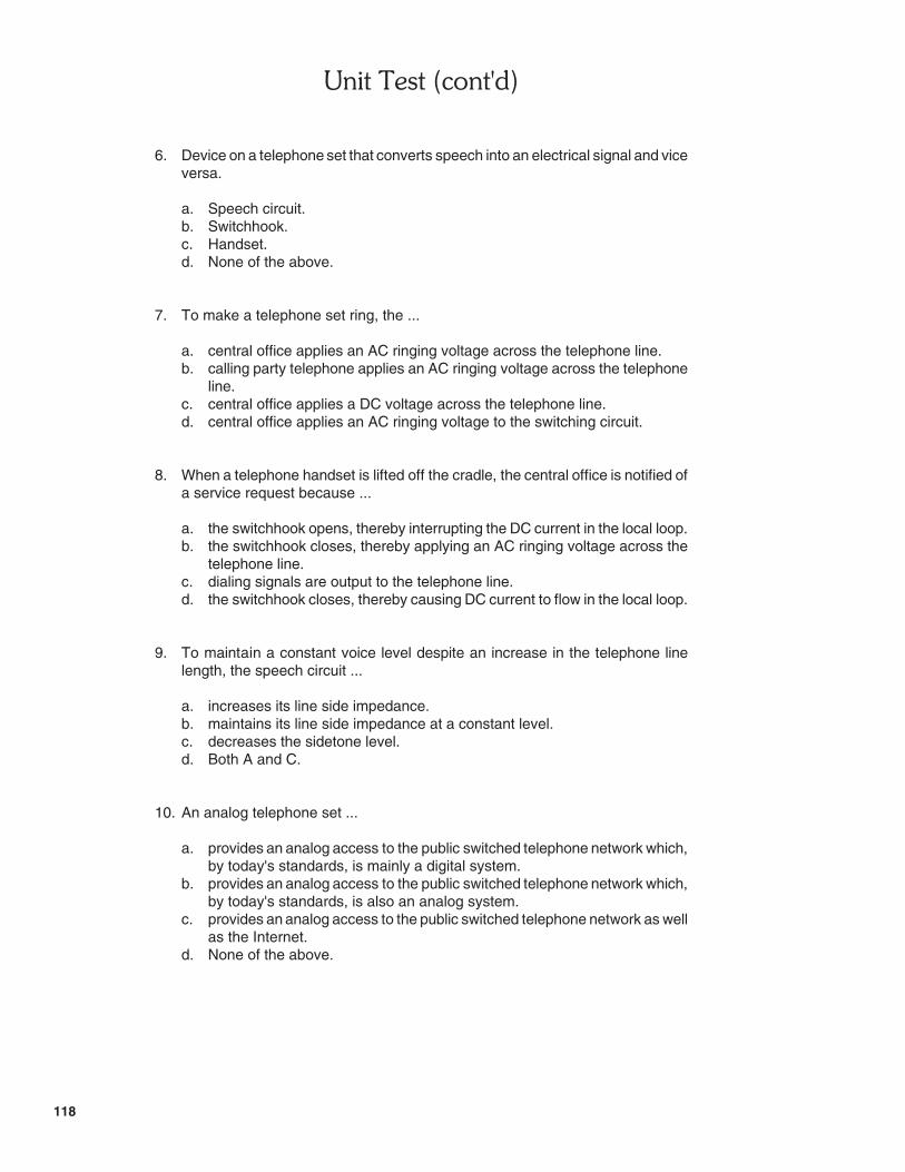
������������� ��
118
6. Device on a telephone set that converts speech into an electrical signal and viceversa.
a. Speech circuit.b. Switchhook.c. Handset.d. None of the above.
7. To make a telephone set ring, the ...
a. central office applies an AC ringing voltage across the telephone line.b. calling party telephone applies an AC ringing voltage across the telephone
line.c. central office applies a DC voltage across the telephone line.d. central office applies an AC ringing voltage to the switching circuit.
8. When a telephone handset is lifted off the cradle, the central office is notified ofa service request because ...
a. the switchhook opens, thereby interrupting the DC current in the local loop.b. the switchhook closes, thereby applying an AC ringing voltage across the
telephone line.c. dialing signals are output to the telephone line.d. the switchhook closes, thereby causing DC current to flow in the local loop.
9. To maintain a constant voice level despite an increase in the telephone linelength, the speech circuit ...
a. increases its line side impedance.b. maintains its line side impedance at a constant level.c. decreases the sidetone level.d. Both A and C.
10. An analog telephone set ...
a. provides an analog access to the public switched telephone network which,by today's standards, is mainly a digital system.
b. provides an analog access to the public switched telephone network which,by today's standards, is also an analog system.
c. provides an analog access to the public switched telephone network as wellas the Internet.
d. None of the above.
)���������+������� �
������������
�� �������������
�� �������������


�� ��������������� �������������
121
UNIT 1 THE TELEPHONE SET
EXERCISE 1-1 TELEPHONE RINGING
ANSWERS TO PROCEDURE QUESTIONS
� 6. The AC ringing voltage is a sine wave.
� 7. AC Ringing Voltage RMS Value: �86 V, can also be set to 45 or 75 V in theTelephony Training System.
AC Ringing Voltage Frequency: 16.7 Hz, 20 Hz (North America), 25 Hz or50 Hz (UK), depending on country.
� 10. The AC ringing voltage is applied momentarily across the telephone line atregular intervals. The telephone set rings whenever the AC ringing voltageis applied across the telephone line, thereby producing a certain ringingcadence.
� 11. The AC ringing voltage is immediately removed from the telephone line tostop telephone ringing.
� 14. Telephone set A stops ringing because the increase of the telephone lineresistance makes the amplitude of the AC ringing voltage across the Tipand Ring terminals decrease below the ringing threshold voltage.
� 15. Ringing Threshold Voltage: �40 V
ANSWERS TO REVIEW QUESTIONS
1. To make an analog telephone set ring, the central office applies an AC ringingvoltage to the corresponding telephone line via the analog line interfaceassociated with that line.
2. In North America, the frequency and RMS voltage values of the AC ringingvoltage are 20 Hz and 86 V, respectively.
3. The telephone rings during 2-s intervals separated by 4-s pauses.
4. Electronic ringer circuits compare the amplitude of the AC ringing voltage to afixed threshold voltage to prevent telephone ringing triggered by undesiredvoltage spikes on the telephone line (such as those induced by lightning forexample).
5. The threshold voltage of the electronic ringer circuit in the analog telephone setsof the Telephony Training System is approximately 40 V.

�����!����� ������������%�����&��'��$
122
EXERCISE 1-2 THE TELEPHONE SWITCHHOOK ANDHANDSET
ANSWERS TO PROCEDURE STEP QUESTIONS
� 6. DC Voltage Across the Telephone Line: �45 V
Note: In the Lab-Volt Telephony Training System, theDC voltage across the telephone line may be a little less thanthe nominal value of �48 V.
The DC voltage across the telephone line comes from a battery feed circuitin the central office.
� 7. No current is flowing through the telephone line because the handset oftelephone set A is on the cradle, thereby leaving the switchhook contactsopen. Therefore, the telephone set is like an open circuit.
� 8. DC Loop Current: 36 mA (handset off the cradle)
Lifting off the telephone handset from the cradle closes the switchhookcontacts. This connects the dialing and speech circuits of the telephone setto the telephone line. These circuits require DC power to operate, hence theDC current flowing through the telephone line.
� 10. The signal at TP3 of ANALOG LINE INTERFACE A represents an electricalequivalent of the voice of the person who is talking into the handset oftelephone set A.
� 12. The signal at TP3 of ANALOG LINE INTERFACE A represents an electricalequivalent of the voice of the person who is talking into the handset oftelephone set B.
The handset microphone converts speech sound waves into an electricalsignal. Conversely, the handset earpiece converts an electrical signal intosound waves. The speech circuit performs 2W/4W conversion, that is, itdirects the voice signal to be transmitted from the handset microphone tothe telephone line, and the received voice signal from the telephone line tothe handset earpiece.
� 13. The voice sound level in the handset earpiece does not change significantlyas the telephone line resistance (length) increases. This is because thetelephone speech circuit is able to increase its line side impedance, therebypreventing the electrical voice signals from being attenuated as thetelephone line resistance (length) increases.

�� ��������������� �������������
123
ANSWERS TO REVIEW QUESTIONS
1. A switchhook is a DPST switch that closes when the telephone handset is liftedoff the cradle.
2. The telephone switchhook connects the dialing and speech circuits to thetelephone line when the handset is off-hook. It is also a means to notify thecentral office of service requests.
3. The speech circuit properly routes the electrical voice signals on the two wiresof the telephone line to the four wires of the handset (this process is referred toas two-wire to four-wire conversion). It also adjusts the level of the voice signalsso as to compensate for different telephone line lengths.
4. Loop length equalization is a process that adjusts the line side impedance of thespeech circuit so that it is inversely proportional to the DC current flowing in thetelephone line. This makes the speech circuit impedance virtually proportionalto that of the telephone line, thereby maintaining the voice signals at a nearlyconstant level.
5. The portion of the voice signal of a telephone user that is sent back to thehandset earpiece is a sidetone. It gives feedback to the telephone user to helpjudge the proper volume at which to speak.
EXERCISE 1-3 TONE DIALING
ANSWERS TO PROCEDURE STEP QUESTIONS
� 7. A DTMF dialing tone is output to the telephone line whenever a key isdepressed on the telephone set. These tones can be heard through thehandset earpiece.
The waveform of the DTMF dialing signals resembles a distorted sine wavethat fluctuates.
� 9. The frequency spectrum of each DTMF dialing signal contains twofrequency components.
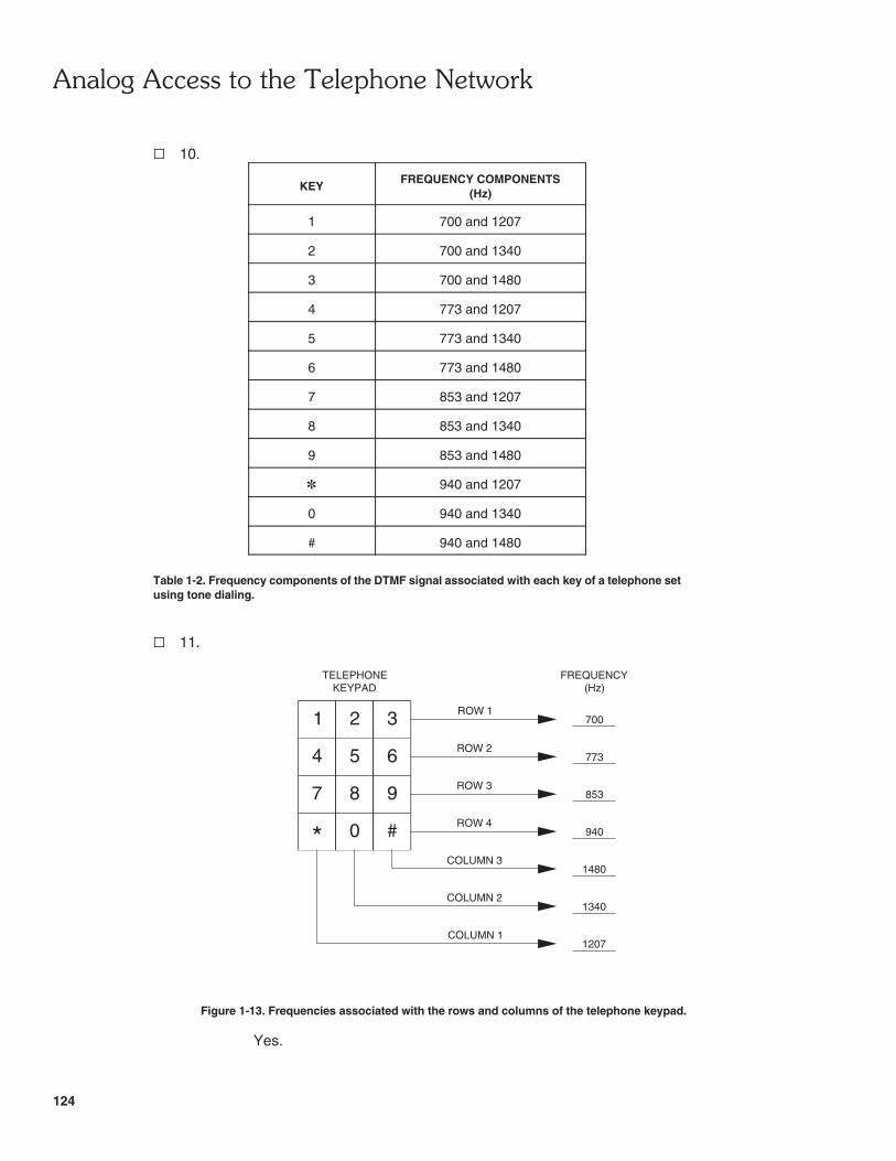
�����!����� ������������%�����&��'��$
124
TELEPHONEKEYPAD
1 2 3
4 5 6
987
* 0 #
ROW 1
FREQUENCY(Hz)
700
773ROW 2
853ROW 3
940ROW 4
1207
1340
1480
COLUMN 1
COLUMN 2
COLUMN 3
� 10.
KEYFREQUENCY COMPONENTS
(Hz)
1 700 and 1207
2 700 and 1340
3 700 and 1480
4 773 and 1207
5 773 and 1340
6 773 and 1480
7 853 and 1207
8 853 and 1340
9 853 and 1480
� 940 and 1207
0 940 and 1340
# 940 and 1480
Table 1-2. Frequency components of the DTMF signal associated with each key of a telephone setusing tone dialing.
� 11.
Figure 1-13. Frequencies associated with the rows and columns of the telephone keypad.
Yes.

�� ��������������� �������������
125
ANSWERS TO REVIEW QUESTIONS
1. DTMF tone dialing is a means of transmitting telephone numbers to the centraloffice using dual-tone audio signals.
2. DTMF tone dialing assigns a specific frequency to each row and column of thetelephone keypad. When a key is depressed, a dual-tone audio signalconsisting of the frequencies associated with the corresponding row and columnof the keypad is output to the telephone line.
3. The frequencies of the DTMF dialing signal associated with number key "8" ofa telephone set are 852 and 1336 Hz.
4. The frequencies associated with the rows of the keypad on a telephone set thatproduces DTMF dialing signals are 697 (upper row), 770, 852, and 941 Hz(lower row).
5. The frequencies associated with the columns of the keypad on a telephone setthat produces DTMF dialing signals are 1209 (leftmost column), 1336,and 1477 Hz (rightmost column).
EXERCISE 1-4 PULSE DIALING
ANSWERS TO PROCEDURE STEP QUESTIONS
� 7. Whenever a number key is depressed on the telephone set, the loopcurrent is briefly interrupted a certain number of times to create a series ofcurrent pulses. These pulses can be heard through the handset earpiece.
� 9. When the digit 6 is dialed, the loop current is interrupted briefly sixsuccessive times since the voltage across the telephone line brieflydecreases to about �45 V six successive times. This produces a series ofcurrent pulses that will be interpreted as the digit 6 in the central office.
� 11. Whenever a digit is dialed on the telephone set, the loop current isinterrupted briefly. The number of current interruptions depends on the digitdialed: one interruption for the digit 1, two interruptions for the digit 2, andso on up to the digit 0 which results in 10 interruptions.
� 12. Dial Pulse Period: 100 ms
Duration of Current Interruptions: 60 ms
Duration of Current Pulses: 40 ms

�����!����� ������������%�����&��'��$
126
� 13. Inter-Digit Interval: 820 ms
ANSWERS TO REVIEW QUESTIONS
1. Pulse dialing is a means of transmitting telephone numbers to the central officethrough a series of momentary loop current interruptions.
2. Pulse dialing momentarily interrupts the loop current several successive timesto transmit a dialed digit to the central office as a series of short current pulses.The number of momentary loop current interruptions that are produced dependson the digit dialed: one interruption for the digit 1, two interruptions for thedigit 2, and so on up to the digit 0 which results in 10 interruptions.
3. Digits dialed with a pulse dialing telephone set are separated by time intervalsof at least 300 ms (nominal duration of 700 ms in North America) during whichthe loop current is not interrupted.
4. In North America, the duration of the loop current interruptions is 60 ms. Inother countries, the duration is about 67 ms.
5. Tone dialing is preferred to pulse dialing because it allows telephone numbersto be dialed more rapidly.
ANSWERS TO UNIT TEST
Unit 1: 1. c, 2. d, 3. b, 4. c, 5. b, 6. c, 7. a, 8. d, 9. d, 10. a

$� �������
Bellamy, John, Digital Telephony, 3rd edition, Wiley-Interscience, New York, 2000.ISBN: 0-471-34571-7
Bigelow, Stephen J., Fike, John L., Friend, George E., Understanding TelephoneElectronics, 3rd edition, Macmillan Computer Publishing, Indiana, 1991ISBN: 0-672-27350-0
Freeman, Roger L., Telecommunication System Engineering, 3rd edition, Wiley-Interscience, New York, 1996
Thompson, Richard A., Telephone Switching Systems, Artech House Inc.,Boston, 2000.ISBN: 1-58053-088-5
Van Bosse, John G., Signaling in Telecommunication Networks, Wiley-Interscience,New York, 1998. ISBN: 0-471-57377-9