e4014 construction surveying road construction plans
TRANSCRIPT
E4014 Construction Surveying
Road Construction Plans
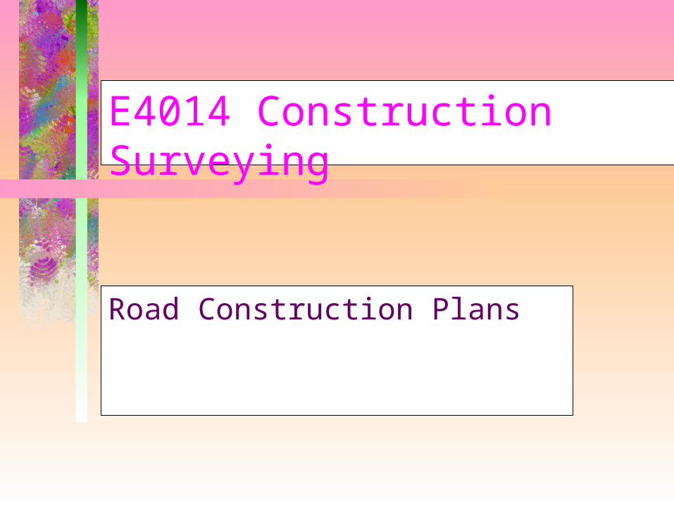
Plan No 239170
• Widening and Overlay and Reconstruction
traffic lane width
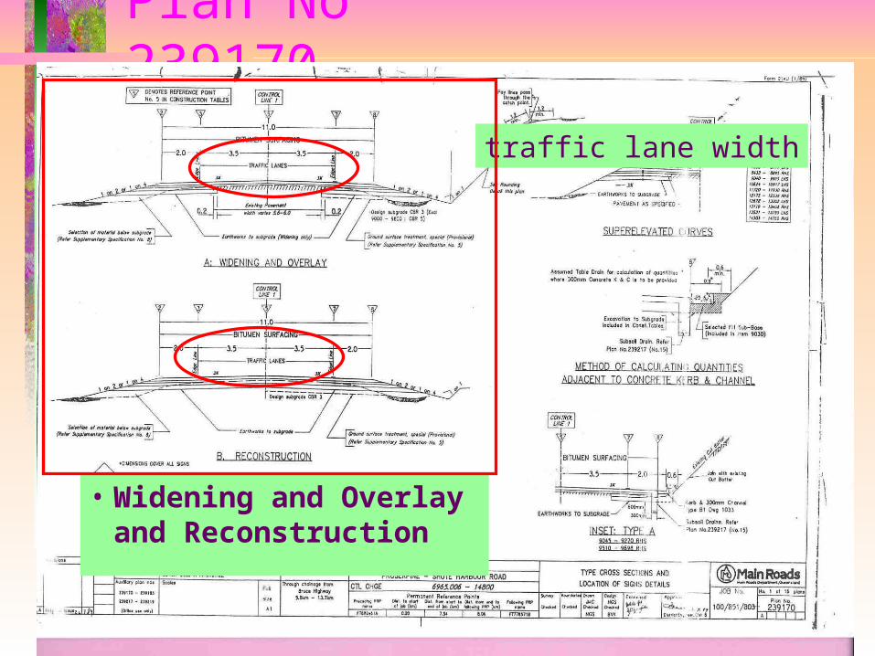
Plan No 239170
• Widening and Overlay and Reconstruction
traffic lane width
shoulder width

Plan No 239170
• Widening and Overlay and Reconstruction
traffic lane width
shoulder width
left and right crossfall
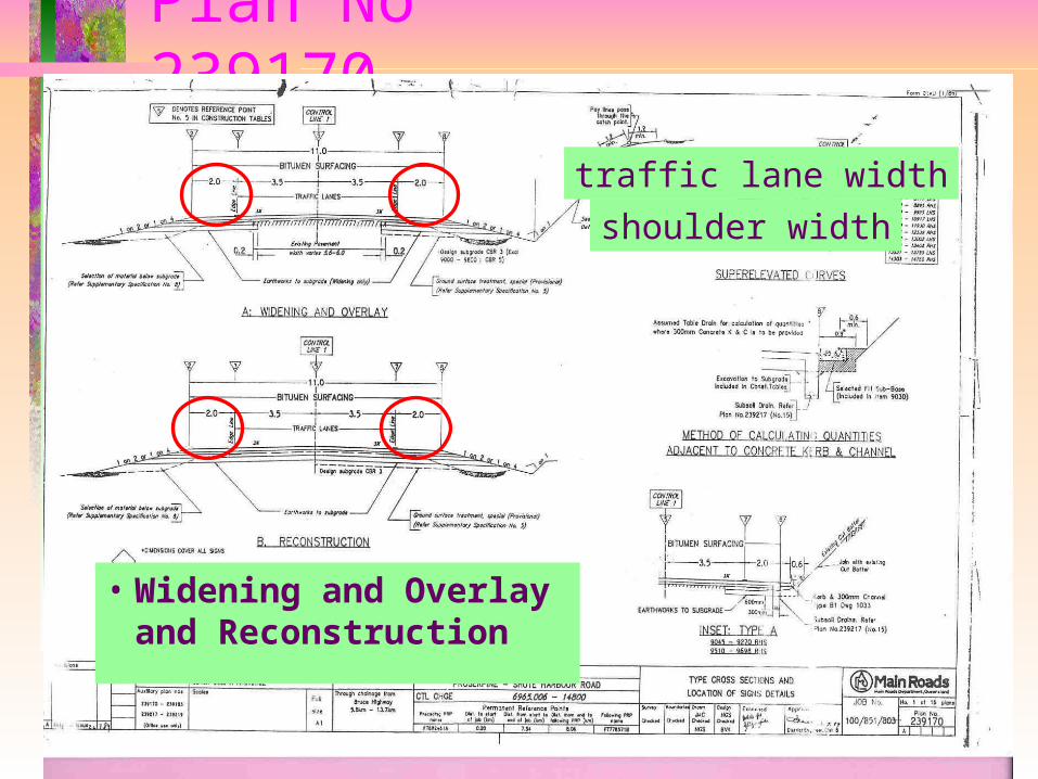
Plan No 239170
• Widening and Overlay and Reconstruction
traffic lane width
shoulder width
left and right crossfall
slope from shoulder
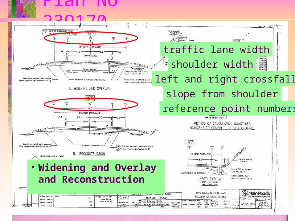
Plan No 239170
• Widening and Overlay and Reconstruction
traffic lane width
shoulder width
left and right crossfall
slope from shoulder
reference point numbers
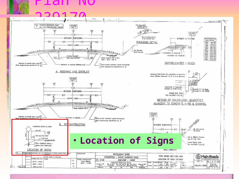
Plan No 239170
• Location of Signs
Plan No 239170
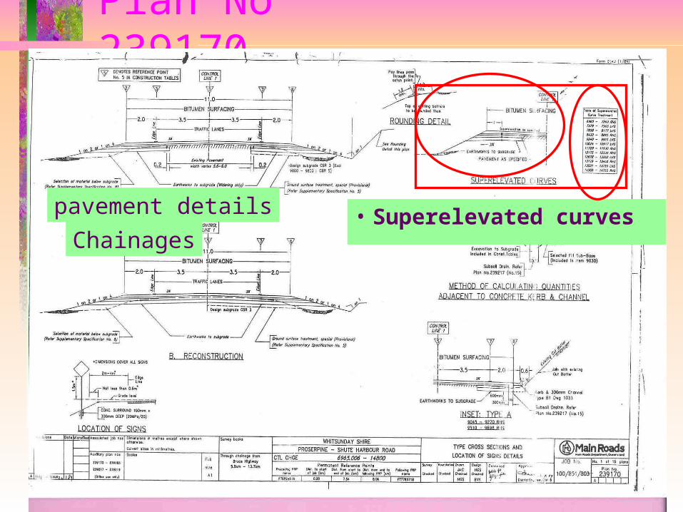
• Superelevated curvespavement details
Chainages
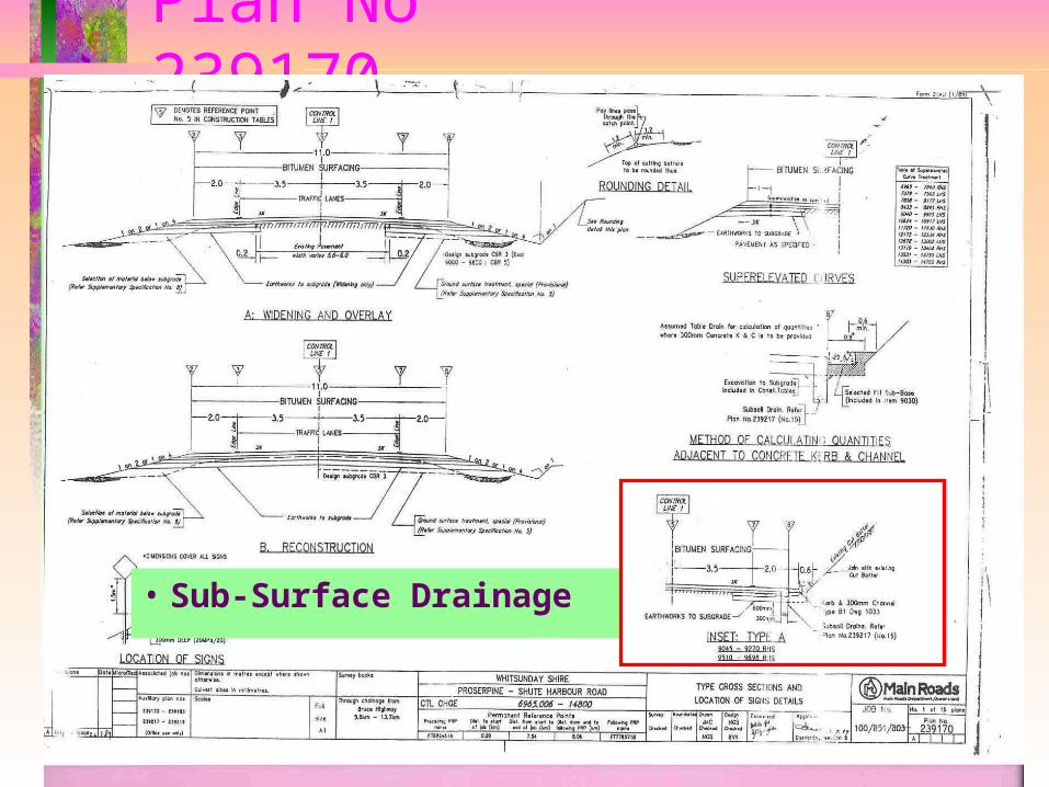
Plan No 239170
• Sub-Surface Drainage
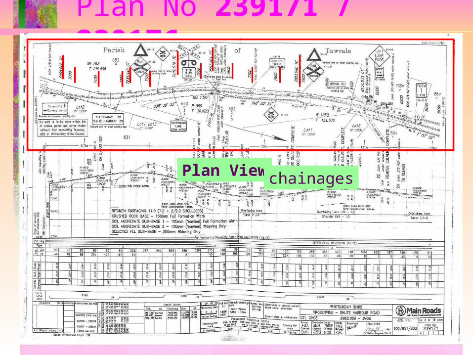
Plan No 239171 / 239176
Plan View chainages
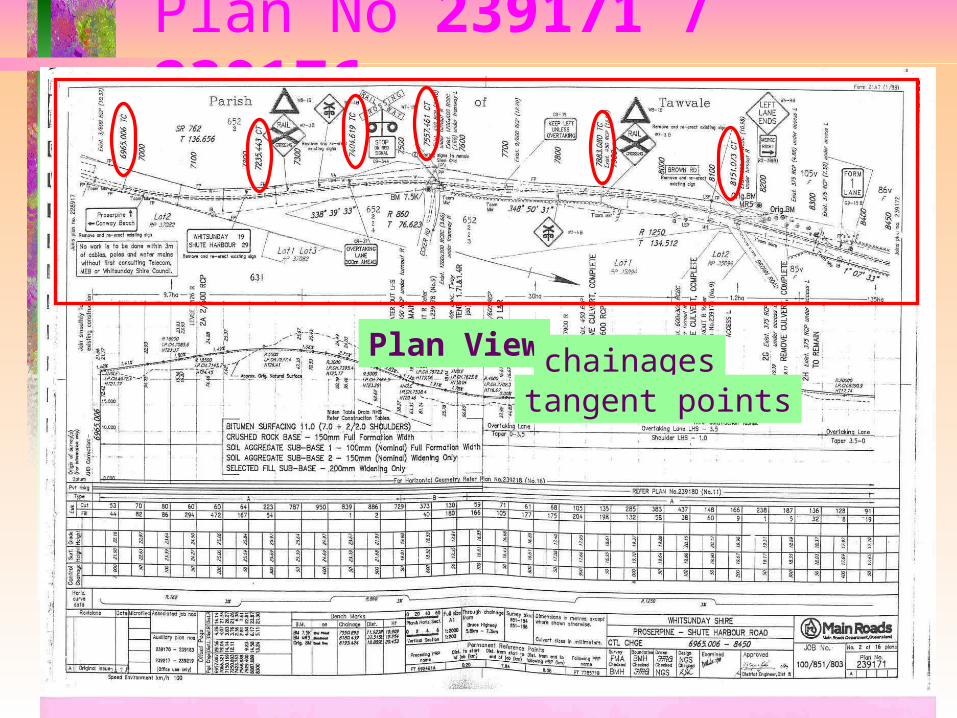
Plan No 239171 / 239176
Plan View chainagestangent points
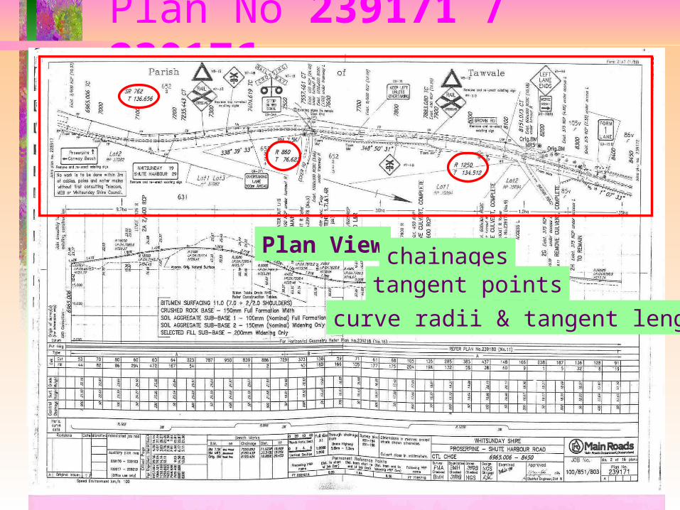
Plan No 239171 / 239176
Plan View chainagestangent points
curve radii & tangent lengths
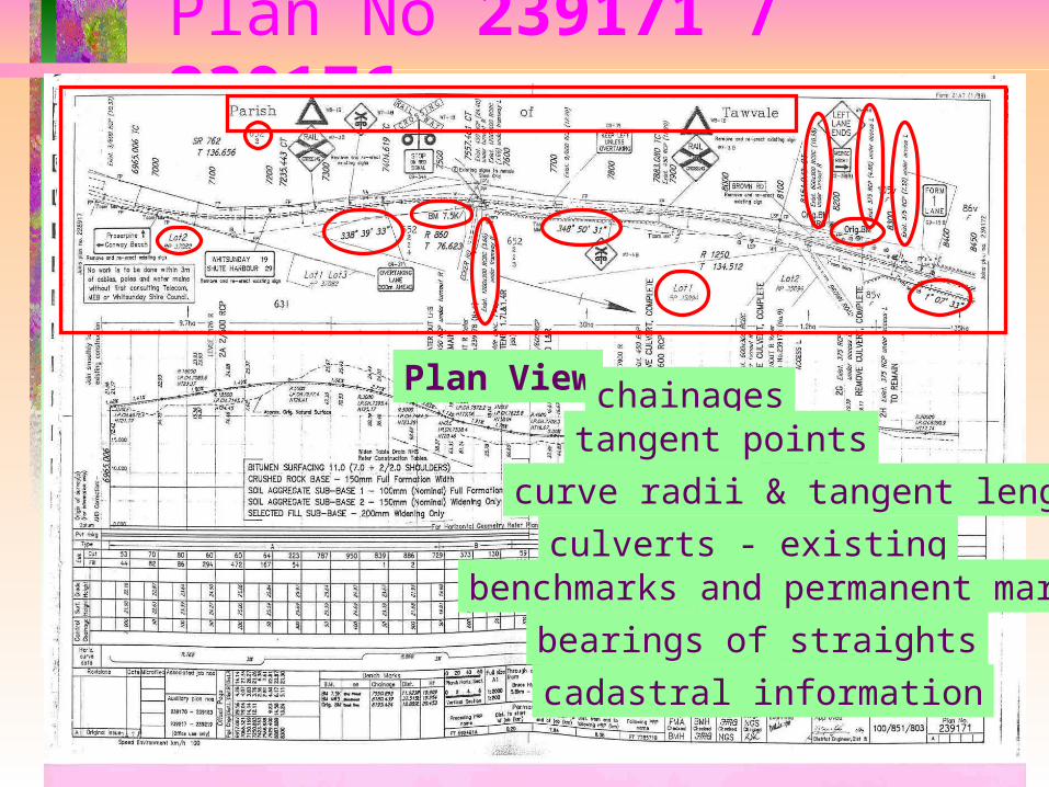
Plan No 239171 / 239176
Plan View chainagestangent points
curve radii & tangent lengths
culverts - existingbenchmarks and permanent marks
bearings of straights
cadastral information
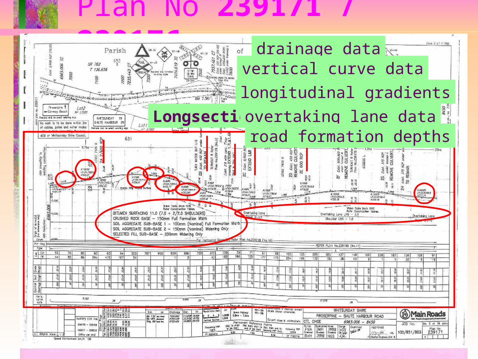
Plan No 239171 / 239176
Longsection
drainage datavertical curve data
longitudinal gradients
overtaking lane dataroad formation depths
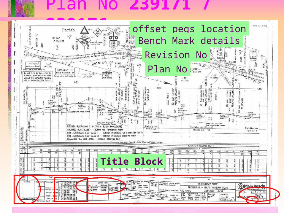
Plan No 239171 / 239176
Title Block
offset pegs locationBench Mark details
Revision No
Plan No
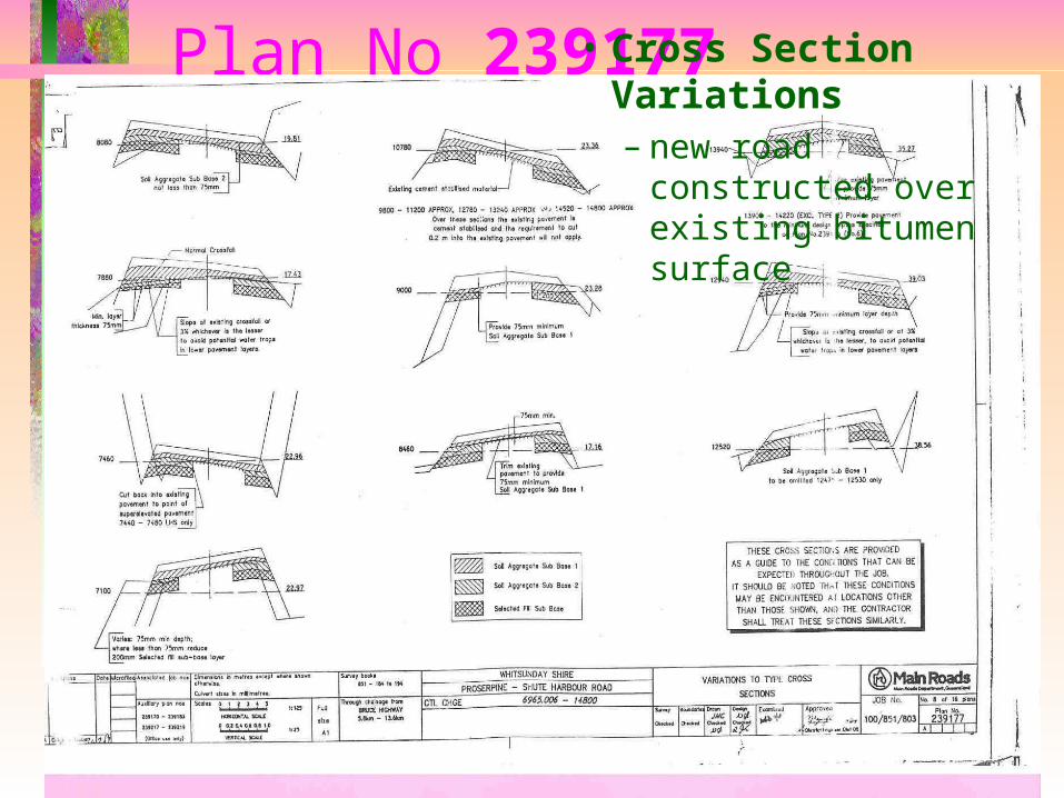
Plan No 239177• Cross Section Variations– new road constructed
over existing bitumen surface
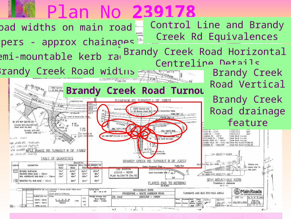
Plan No 239178
Brandy Creek Road Turnout
road widths on main road
tapers - approx chainages
semi-mountable kerb radii
Brandy Creek Road widths
Control Line and Brandy Creek Rd Equivalences
Brandy Creek Road Horizontal Centreline Details
Brandy Creek Road Vertical Details
Brandy Creek Road drainage feature
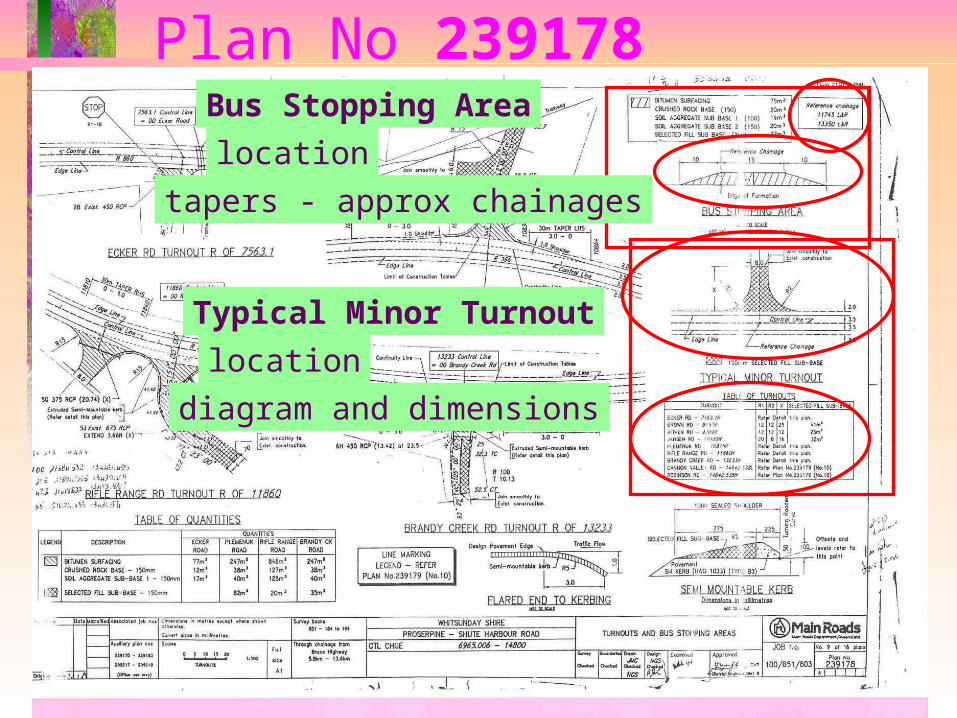
Plan No 239178Bus Stopping Area
location
tapers - approx chainages
Typical Minor Turnout
location
diagram and dimensions
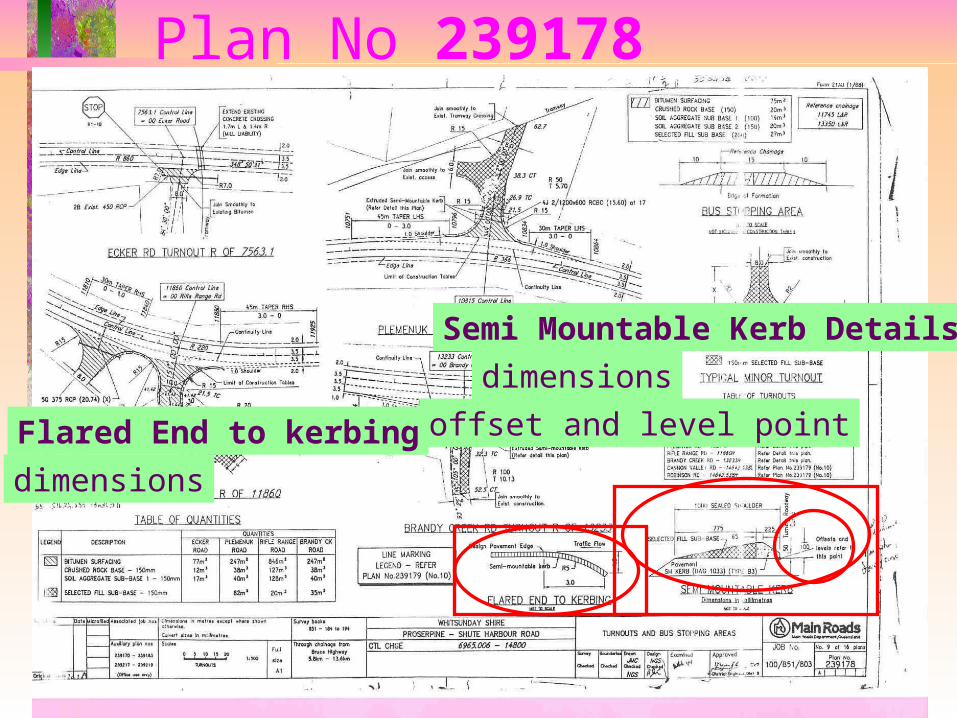
Plan No 239178
Semi Mountable Kerb Details
dimensions
offset and level pointFlared End to kerbing
dimensions
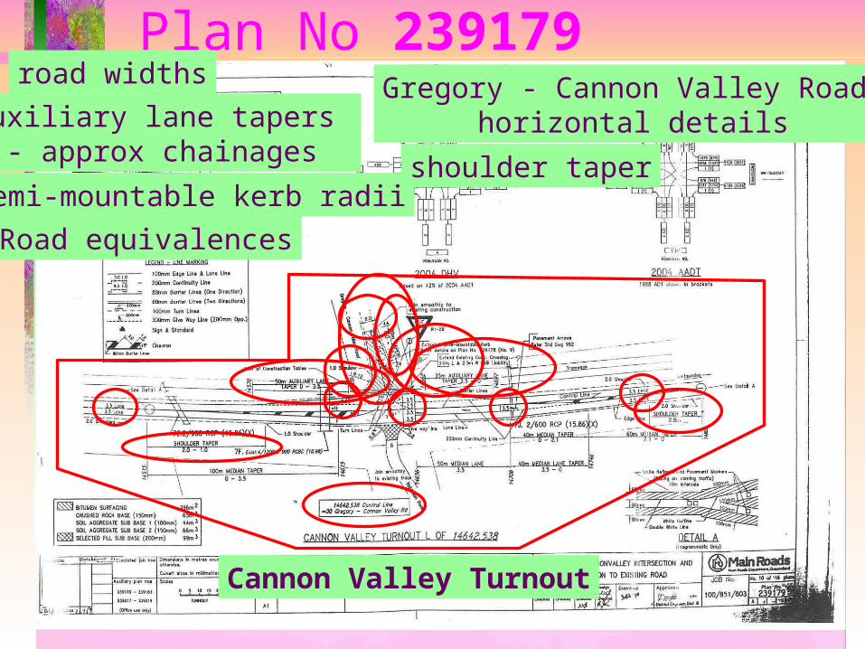
Plan No 239179
Cannon Valley Turnout
road widths
Auxiliary lane tapers - approx chainages
semi-mountable kerb radii
Road equivalences
Gregory - Cannon Valley Road horizontal details
shoulder taper
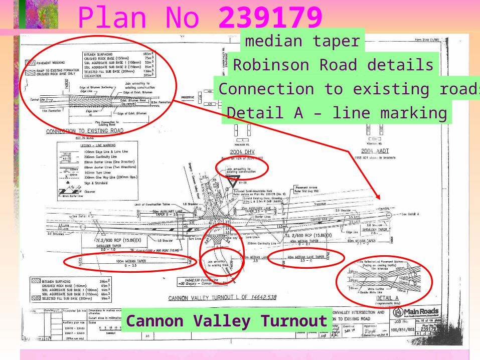
Plan No 239179
Cannon Valley Turnout
median taper
Robinson Road details
Connection to existing roads
Detail A – line marking
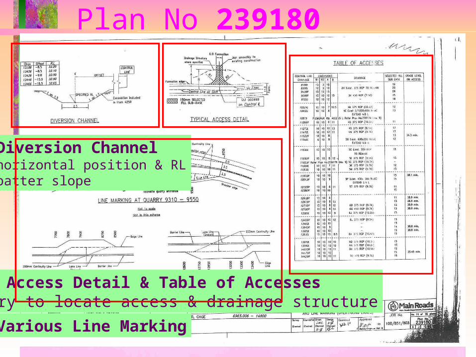
Plan No 239180
Diversion Channelhorizontal position & RLbatter slope
Typical Access Detail & Table of Accessesnecessary to locate access & drainage structure
Various Line Marking
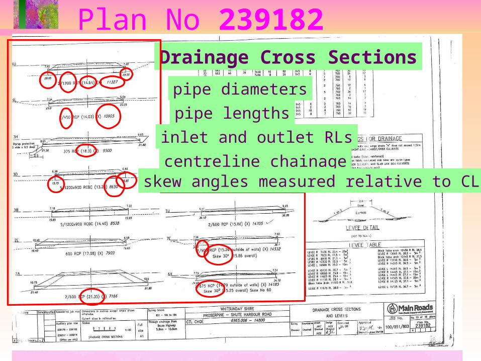
Plan No 239182Drainage Cross Sections
pipe diameters
pipe lengths
inlet and outlet RLs
centreline chainageskew angles measured relative to CL
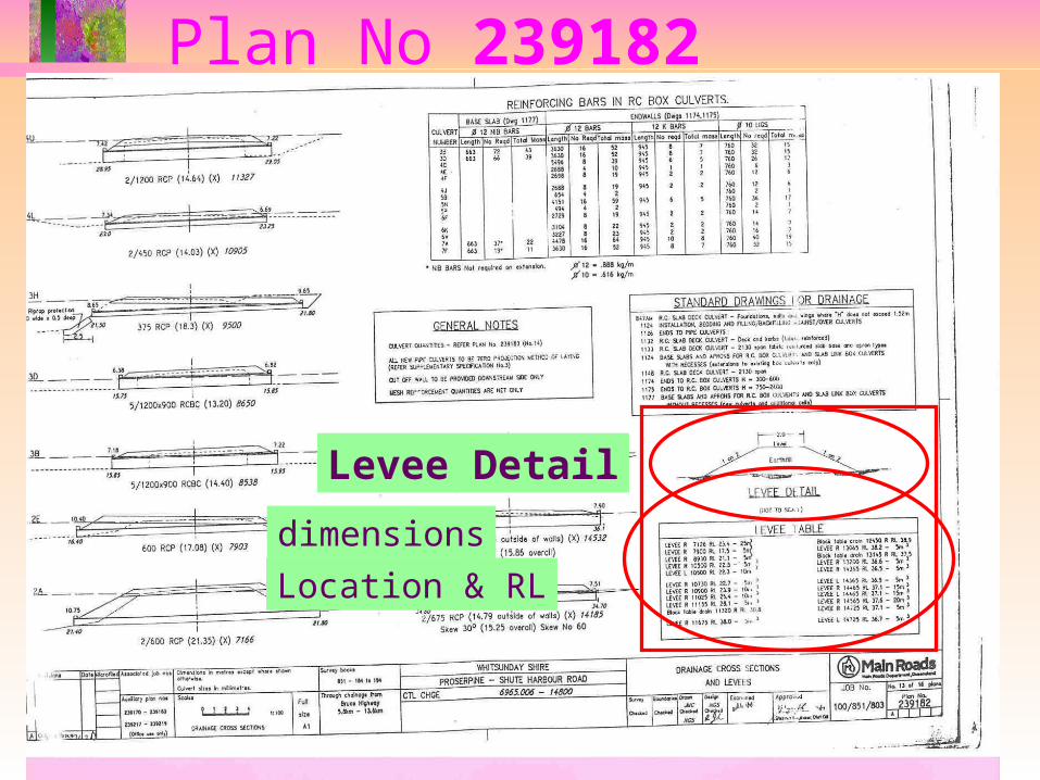
Plan No 239182
Levee Detail
dimensions
Location & RL
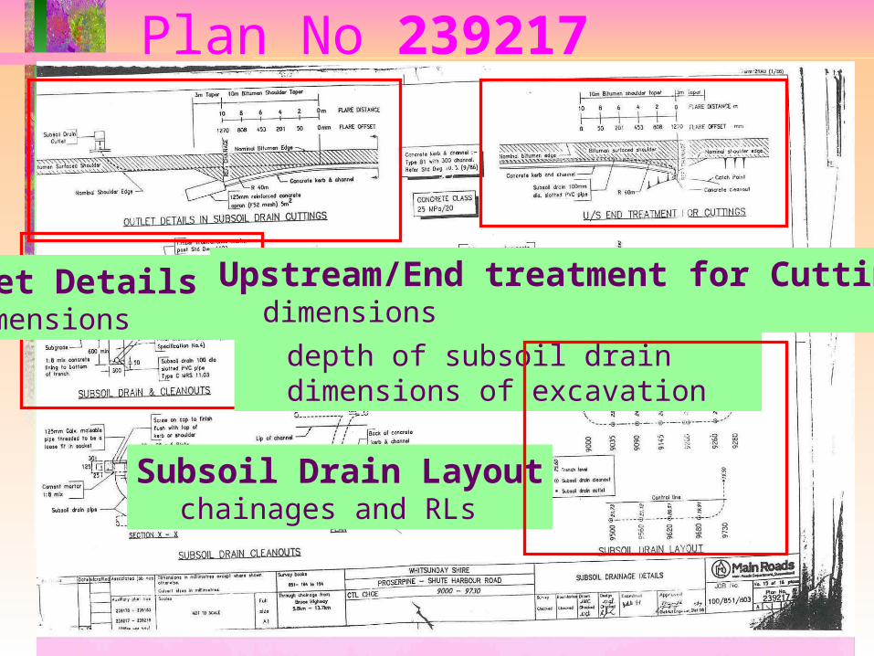
Plan No 239217
Subsoil Drain & cleanoutsdepth of subsoil draindimensions of excavation
Outlet Details in Subsoil Drain Cuttingsdimensions
Upstream/End treatment for Cuttingsdimensions
Subsoil Drain Layoutchainages and RLs
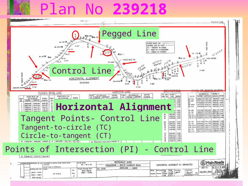
Plan No 239218
Horizontal Alignment
Control Line
Pegged Line
Tangent Points- Control LineTangent-to-circle (TC)Circle-to-tangent (CT)
Points of Intersection (PI) - Control Line
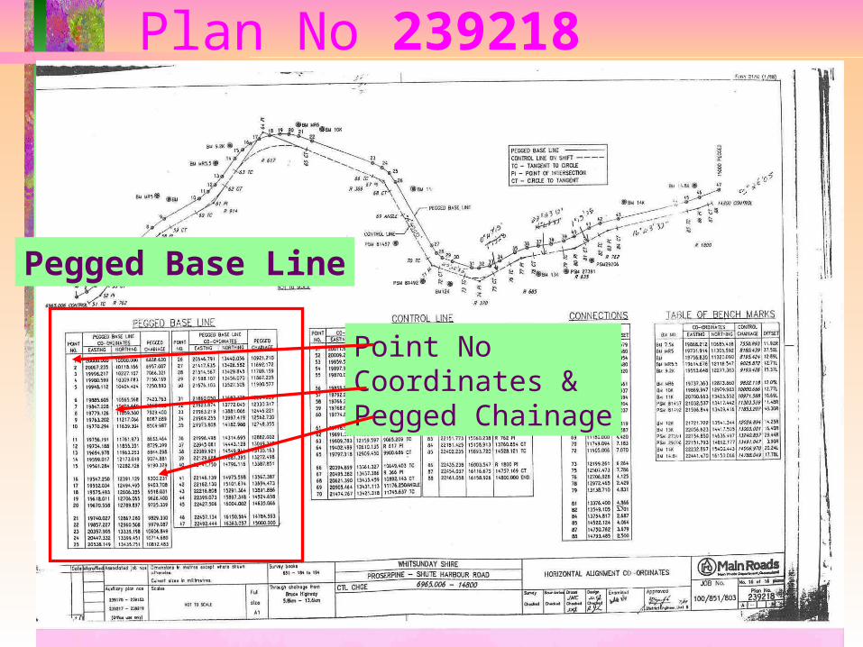
Plan No 239218
Pegged Base Line
Point NoCoordinates &Pegged Chainage
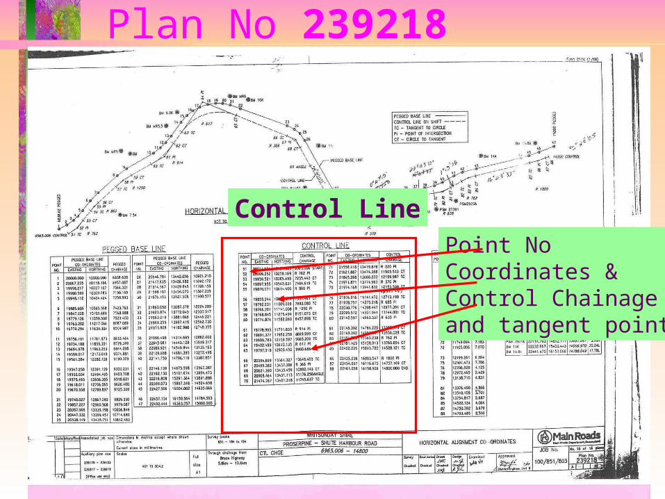
Plan No 239218
Control LinePoint NoCoordinates &Control Chainageand tangent points
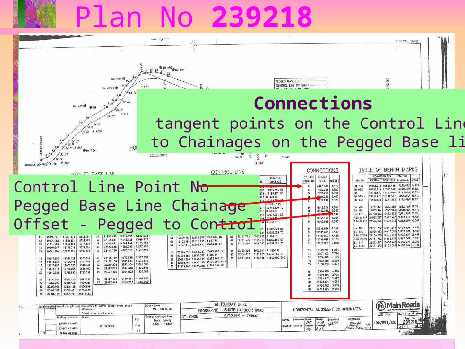
Plan No 239218
Connectionstangent points on the Control Line
to Chainages on the Pegged Base line
Control Line Point NoPegged Base Line ChainageOffset - Pegged to Control
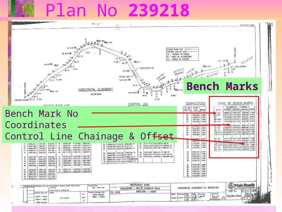
Plan No 239218
Bench Marks
Bench Mark NoCoordinatesControl Line Chainage & Offset
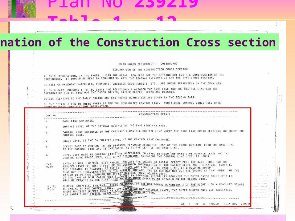
Plan No 239219 Table 1 - 12
Explanation of the Construction Cross section
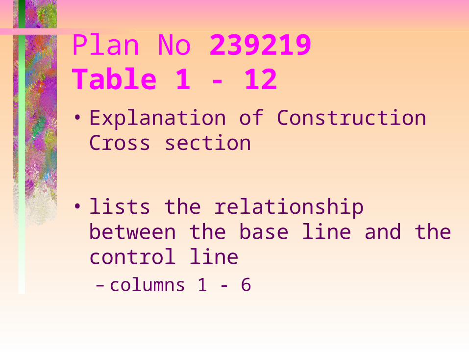
Plan No 239219 Table 1 - 12• Explanation of Construction Cross
section
• lists the relationship between the base line and the control line– columns 1 - 6
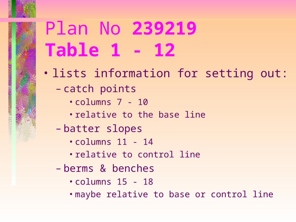
Plan No 239219Table 1 - 12• lists information for setting out:
– catch points• columns 7 - 10• relative to the base line
– batter slopes• columns 11 - 14• relative to control line
– berms & benches• columns 15 - 18• maybe relative to base or control line
Plan No 239219Table 12
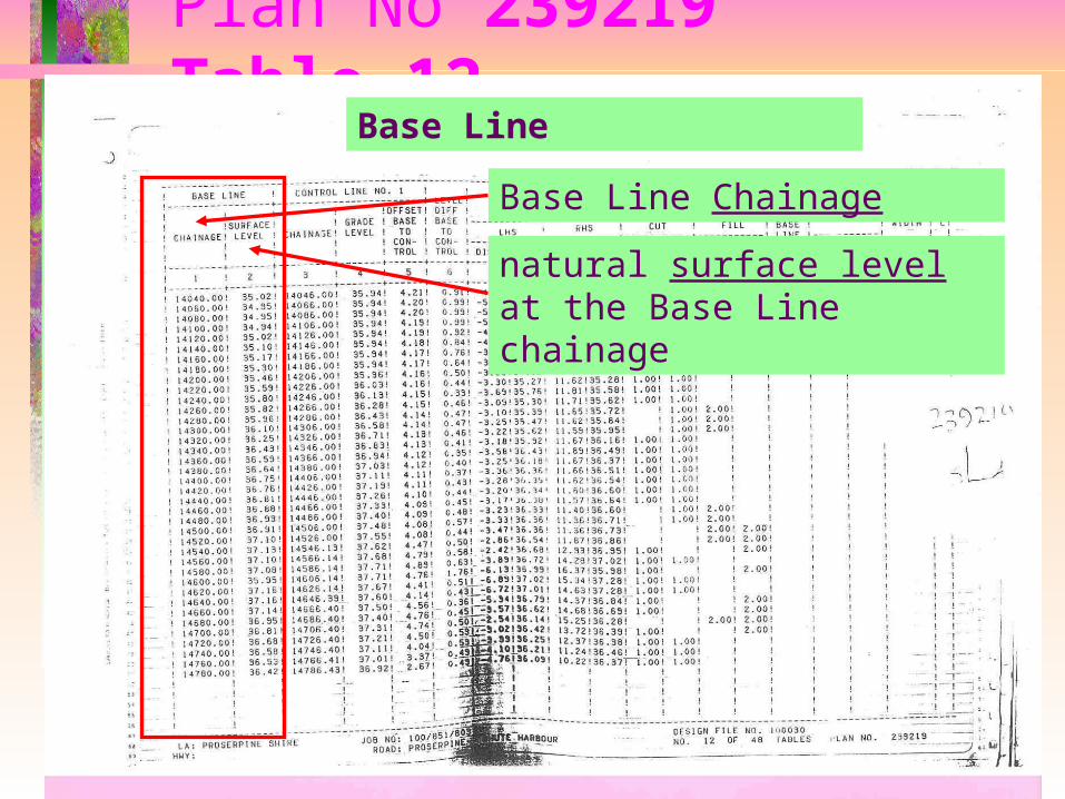
Base Line Chainage
Base Line
natural surface level at the Base Line chainage
Plan No 239219Table 12
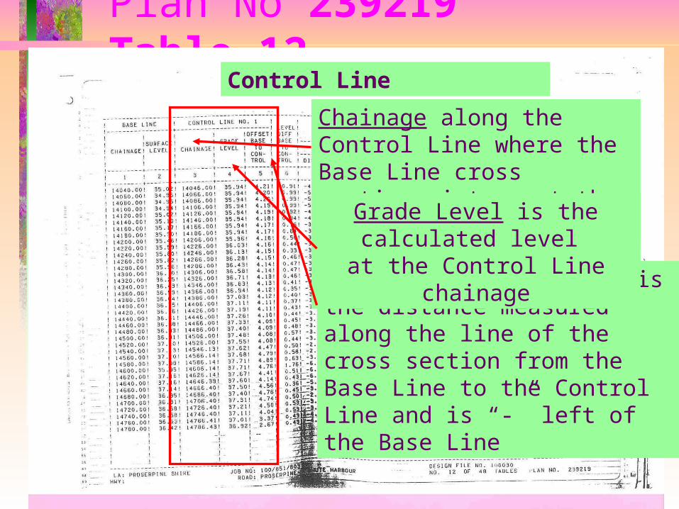
Chainage along the Control Line where the Base Line cross sections intersect the Control Line
Offset Base to Control is the distance measured along the line of the cross section from the Base Line to the Control Line and is “-” left of the Base Line
Control Line
Grade Level is the calculated level at the Control Line chainage
Plan No 239219Table 12
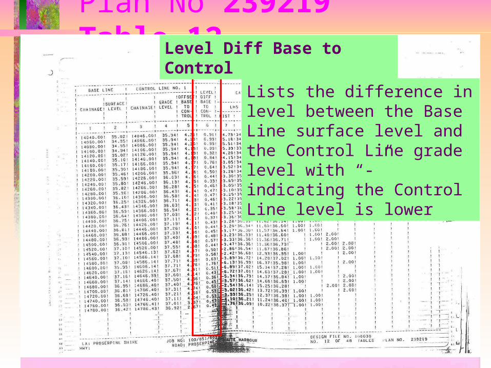
Lists the difference in level between the Base Line surface level and the Control Line grade level with “-” indicating the Control Line level is lower
Level Diff Base to Control
Plan No 239219Table 12
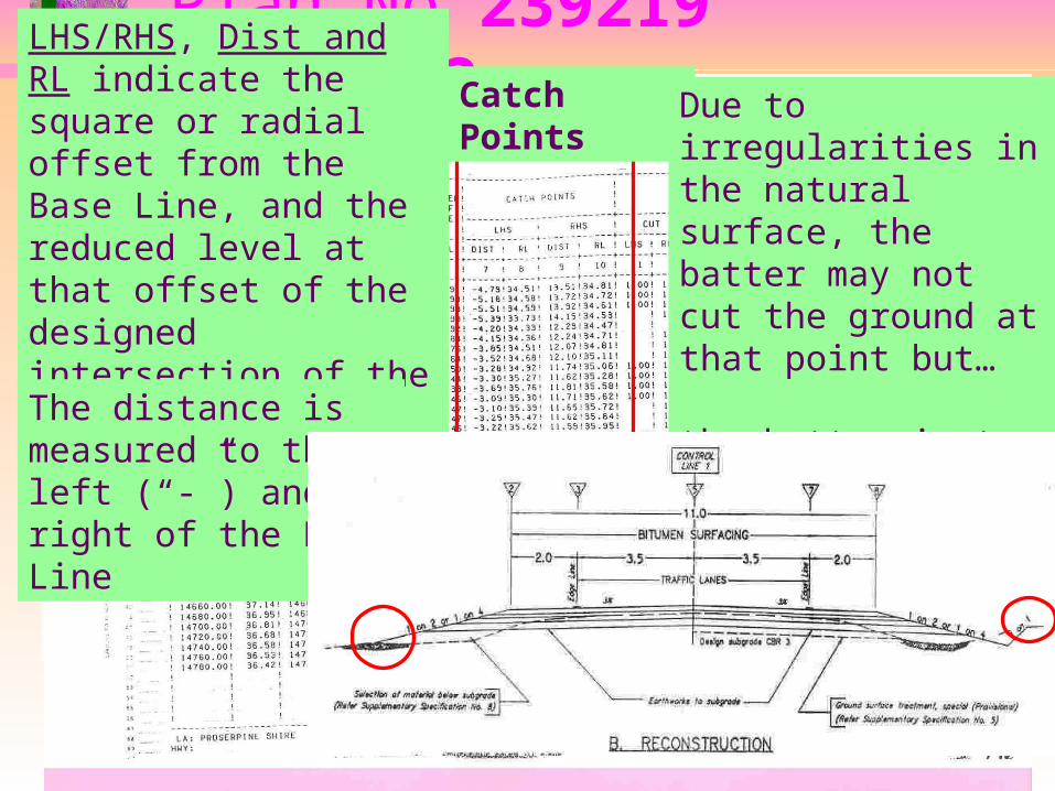
LHS/RHS, Dist and RL indicate the square or radial offset from the Base Line, and the reduced level at that offset of the designed intersection of the batter slope and the natural surface
Catch Points
The distance is measured to the left (“-”) and right of the Base Line
Due to irregularities in the natural surface, the batter may not cut the ground at that point but…
the batter is to pass through the offset DIST/RL point as designed
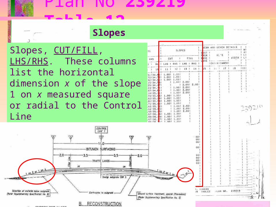
Plan No 239219Table 12
Slopes, CUT/FILL, LHS/RHS. These columns list the horizontal dimension x of the slope 1 on x measured square or radial to the Control Line
Slopes
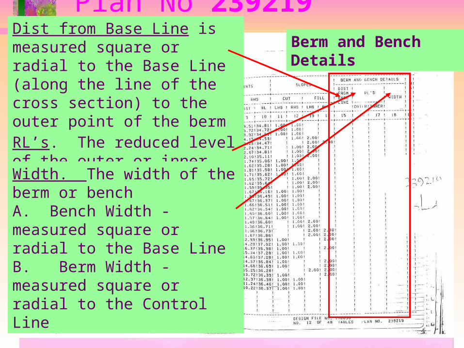
Plan No 239219Table 12Dist from Base Line is measured
square or radial to the Base Line (along the line of the cross section) to the outer point of the berm or bench
Berm and Bench Details
RL’s. The reduced level of the outer or inner berm or bench points
Width. The width of the berm or benchA. Bench Width - measured square or radial to the Base LineB. Berm Width - measured square or radial to the Control Line
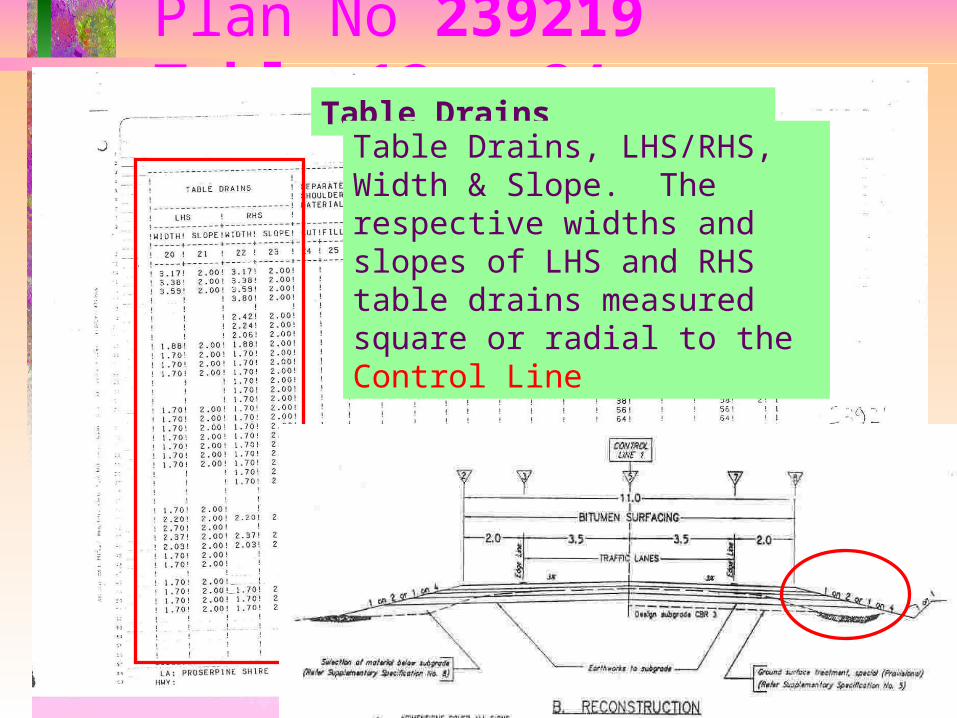
Plan No 239219Table 13 - 24
Table Drains
Table Drains, LHS/RHS, Width & Slope. The respective widths and slopes of LHS and RHS table drains measured square or radial to the Control Line
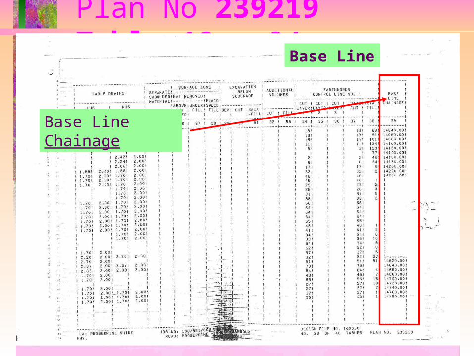
Plan No 239219Table 13 - 24
Base Line Chainage
Base Line
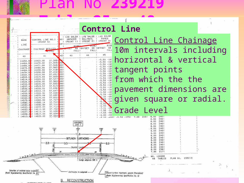
Plan No 239219Table 25 - 48
Control Line
Grade Level
Control Line Chainage10m intervals including horizontal & vertical tangent pointsfrom which the the pavement dimensions are given square or radial.
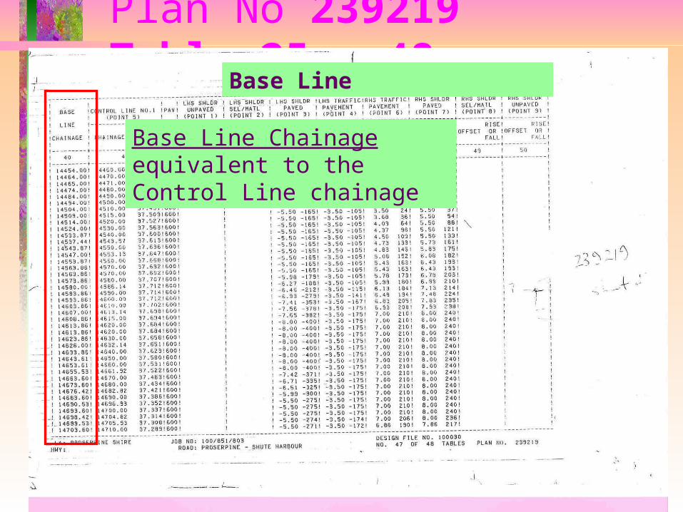
Plan No 239219Table 25 - 48
Base Line
Base Line Chainageequivalent to the Control Line chainage

Plan No 239219Table 25 - 48
Pavement Depth
Total depth of pavement is shown in millimetres (mm)
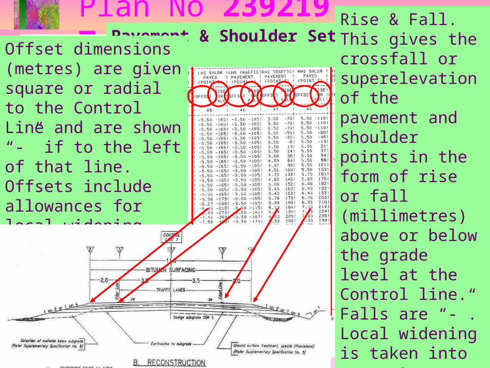
Plan No 239219Table 25 - 48Pavement & Shoulder Setting Out
Offset dimensions (metres) are given square or radial to the Control Line and are shown “-” if to the left of that line.Offsets include allowances for local widening.
Rise & Fall. This gives the crossfall or superelevation of the pavement and shoulder points in the form of rise or fall (millimetres) above or below the grade level at the Control line.Falls are “-”.Local widening is taken into account.