developments of surveying technologies in construction history · proceedings of the third...
TRANSCRIPT

Proceedings of the Third International Congress on Construction History, Cottbus, May 2009
OVERVIEW OF THE HISTORICAL DEVELOPMENT OF SURVEYING TECHNOLOGY
The oldest evidence of the use of technical surveying equipment goes back to the 3rd Millennium BC. Egyp-tians, Chinese, Babylonians and Sumerian used poles, plumbs and water levels for measuring their fields and for the construction of roads, canals and human-made structures (Deumlich; Staiger, 2002, pp. 19-20). The Greeks adopted and enhanced devices such as the "Gnomon", the so called quadratum for indirect dis-tance measurement. The most important surveying device of Roman times was the Groma, a field cross for measuring and setting up angles. A great contribution of the Romans was their dissemination of surveying in-struments to Central Europe. The demands of land and field surveying significantly determined the development of measuring instruments in ancient times as well as in the Middle Ages and up to the 19th century. Seafaring and astronomy, in particular in the 16th and 17th centuries, had an important influence. The measur-ing of constructions – today a part of engineering surveying - played a minor role. This can be explained in part by the fact that the accuracy requirements, especially for angle measurement, were obviously higher in land surveying and astrometry, which in turn promoted the development of more precise angle measurement devices (theodolites). Moreover, most measuring tasks in construction could be solved by mechanical dis-tance measuring with measuring strings, so it was not necessary to use angle measuring instruments. The Dutchman Hans Lipperhey built the first telescope in 1608 and in the following year Galileo Galilei im-proved and used it for astronomical observations. Telescopes have been an essential component of geodetic instruments and remain so today. However telescopes have been used for geodetic instruments only since 1640 when William Gascoigne installed a crosshair as a precise target device. The telescope displaced the di-opter, which had been used before, and over the course of time, telescopes increased the precision of theo-dolites and levels. In the 17th and 18th century the accuracy of angle measuring devices was improved by telescopes with a higher magnification, by new reading mechanisms and by finer, more precise mechanical manufacturing (Deumlich; Staiger, 2002, pp. 22-24). The natural sciences boom along with evolving precision techniques were the major factors leading to the development and perfection of instrument technology at that time. In 1629 Branca developed a hydrostatic level. But it was only in 1849, when Geiger advanced this instrument, that the hydrostatic level replaced the mechanical level at the base of plumb lines, pendulum and simple wa-
ABSTRACT: The investigation, construction and documentation of buildings and their constructive details is in-trinsically tied to the development of geodetic and photogrammetric surveying methods. From ancient times to the 18th century elementary methods based on mechanical distance measurement and simple angle measurement have been used for building construction surveys. 150 years ago the German civil engineer Albrecht Meydenbauer developed photogrammetric measurement techniques as an alternative method to the traditional manual measurement. The ideas and methods Meydenbauer developed are effective to this day. More than 100 years ago, photogrammetry asserted oneself as the most effective method for building measurement. In the second half of the 20th century, electronic surveying instruments such as electro-optical tacheometers, electronic level instruments, digital cameras, global positioning systems and laser scanning revolutionized surveying technologies. The paper gives an overview of geodetic and photogrammetric meas-urement techniques for construction surveying. The application of several methods is presented through se-lected examples of historic and current construction projects.
Developments of Surveying Technologies in Construction History
Frank Henze, Katja Heine Brandenburg University of Technology, Cottbus, Germany
Gunnar Siedler Fokus GmbH Leipzig, Germany

Proceedings of the Third International Congress on Construction History, May 2009
ter level which already had been in use since ancient times. Hydrostatic levels in simple form have been used for building measurement up to our time. Precise automatic hydrostatic level systems are used today for de-formation monitoring. Spirit levels, which were used up to the end of the 20th century, go back to the invention of the tubular value by Thévenot in 1662 (Deumlich; Staiger, 2002, p. 23). The improvement of level instruments during the following 300 years also depended mainly on the development of telescopes. At the beginning of the 20th century various improvements like internal focusing and optical micrometers con-tributed to further perfection of theodolites and level instruments. The first optical theodolite with the same configuration we use today was produced in 1924 by the Carl Zeiss Jena Company (Deumlich; Staiger, 2002, p. 26). Until the 18th century, distance measurement was realized exclusively by mechanical devices such as rods, poles and measuring strings. The principle of optical distance measurement is based on the determination of the distance by measuring the parallactic angle. James Watt built a distance meter according to this principle in 1771. Although several improvements and modifications of optical distance measurement were subse-quently realized, the fundamental principle remained unchanged until the middle of the 20th century. Be-cause of its relatively low accuracy, the optical distance measurement did not play a role in engineering sur-veying. Instead mechanical measurement techniques, well known for thousands of years, were used for more precise measurements up to the 1960s. After the Second World War instrument technology underwent an almost revolutionary development. The in-troduction of electronic distance measurement on the basis of microwaves in the 1950s and on the basis of electro-optical waves in the early 1960s combined the advantages of mechanical measurement (high accu-racy) with those of optical (short measurement time). Electro-optical instruments have been used increasingly in engineering surveying since the 1970s, when dis-tance measurement instruments for short distances began to be serially produced. The electro-optical instru-ments used today offer total accuracy of the distance measurement in mm-range and therefore they are at least on par with mechanical measurement methods. The introduction of electronic angle measurement in the 1980s as well as electronic level instruments in the 1990s also contributed significantly to the improvement of accuracy and productivity. These essential instrument innovations changed land surveying fundamentally within a few years. Since the 1990s, global positioning systems, the best-known of which is American Navstar GPS, have constituted a veritable revolution. The principle of GPS differential phase measurement allows a de-termination of positions with an accuracy of within a few mm. The main advantage in comparison with the use of an electro-optical total station is that no expensive network measurements have to be made before staking building measurements are done. A second revolutionary procedure of the recent years is laser scanning (Fig. 1), which is only suitable for building recording, but not for staking. The enormous changes in the surveying of recent years are undoubtedly linked with the development of computer technology and microelectronics, without whose support the production of ever more powerful and convenient measurement instruments would be unthinkable. Furthermore the instrument developments of recent years have changed the occupational image of surveying engineering completely. One could assert that today land surveying is a cake-walk by means of the convenient instruments that have been launched especially for the construction sector. How-ever it should be remembered that throughout the millennia, engineering expertise and knowledge of mathe-matics and physics have been the fundamental basis of surveying engineering services and they will continue to be so in the future.
Figure 1: Intensity image of an 360° laser scan of the roof structure at St. Petri Cathedral in Bautzen/Germany
for constructional survey and research on building history; (Henze et al 2005)
PHOTOGRAMMETRIC TECHNIQUES
Photogrammetric techniques make it possible to get metric object information by means of indirect meas-urements within photogrammetric images. Thus, photogrammetric recordings are used for as-built documen-tation and measurement. For real-time monitoring of construction processes and for setting out of buildings, normally geodetic methods are used (see above). In contrast to hand measurements or tacheometry, photo-grammetric recordings offer a pictured and non-interpreted object documentation along with the possibility of obtaining geometric information. So it is possible to use photogrammetric and photographic images for a later analysis of completely new aspects. Some examples of the analysis of historic images can be found in (Hemmleb 1999), (Heuvel 2001), (Wiedemann et al 2000), (Bräuer-Burchardt; Voss, 2001) or (Henze; Lehamnn, in prep.). For engineering or industrial surveying, adapted photogrammetric procedures are applied for con-

Proceedings of the Third International Congress on Construction History, May 2009 trolling, monitoring and documentation of buildings and building components, structural elements and mod-els. One advantage of photogrammetry over discrete measurement methods is the simultaneous recording of all object points of interest within one (or several) image(s). Consequently, the recording and analysis of dy-namic processes is one of the application areas of industrial photogrammetry. Further examples can be found in Regensburger, 1990; Atkinson, 1996 or Luhmann, 2000. Photogrammetric methods have also been an impor-tant tool for object documentation in archaeology, building archaeology, preservation and restoration for more than 100 years. The applications range from simple photo documentation for archaeology and preser-vation (Eckstein 2003), to image interpretation for damage mapping (Schäfer 2001) and the provision of met-ric image maps for reconstruction and restoration (Hemmleb et al 2001, Wulf-Rheidt; Henze, 2008) up to the generation of complex 3D models for research in building archaeology and construction history (Bührer et al 2001, Heine et al 2006). The proceedings of the CIPA symposia (http://cipa.icomos.org) offer a comprehensive overview over the application of photogrammetry for documentation of cultural heritage.
Figure 2: Rectified image map (left) and elevation drawing (right) as basis for damage analysis and restoration
at St. Petri Cathedral in Bautzen/Germany; (Wulf-Rheidt; Henze, 2008) Some important stages in 150 years of development in architectural and close range photogrammetry are re-viewed below.
150 years of architectural photogrammetry
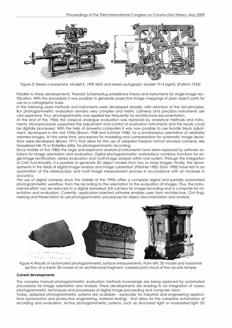
The development of photogrammetry began 150 years ago in connection with the documentation of the ca-thedral of Wetzlar/Germany by the young architect Albrecht Meydenbauer (1834 - 1921). While making mea-surements by hand in 1858 he barely escaped a fall from the nearly 20 meter high scaffold. This event gave him the idea of obtaining all metric information of a building façade from photographic images by inversion of the perspective drawing process (Meydenbauer 1911). During the following 25 years, parallel to his work as a building officer, Meydenbauer developed methods and instruments for photogrammetric object documen-tation. His engagement culminated in the establishment of the “Königlich Preußische Meßbildanstalt” (Royal Prussian Photogrammetric Institut) in 1885. Under his direction until 1909 more than 1,100 buildings and monu-ments were collected within more than 13,000 survey photographs (Grimm 1977). Most of these images, to-gether with recordings of the following years, are stored in the “Messbildarchiv” (Photogrammetric Archive) at “Brandenburgisches Landesamt für Denkmalpflege” (Office for the Preservation of Monuments Brandenburg). The photographs of the so-called “Meydenbauer Archive” are priceless for use in the reconstruction of de-stroyed buildings (see below) and they impressively demonstrate the very high information and documenta-tion content of photogrammetric images. Until the beginning of the 20th century, graphical evaluation using plane table or intersection photogrammetry was very complex and therefore, photogrammetry was rarely used. The development of the stereo comperator (Fig. 3, left) in 1901 by Carl Pulfrich allowed for the precise meas-urement of parallaxes and the derivation of depth information directly from stereoscopic image pairs (Szan-golies 1986). In combination with a mechanical stereo plotter (Autostereograph or Stereoautograph) it was possible to generate line drawings without any calculation process (Fig. 3, right). The new technology was used not only for topographic and engineering recordings for railway projects, dams, water channels and sur-face mining (Pulfrich 1923) but also for architectural and close range photogrammetry. The basic methods and instruments of stereoscopic evaluation were used in numerous offices and institutions until the beginning of the 1990s (Grün 1994 and Eckstein 2003).
Proceedings of the Third International Congress on Construction History, May 2009
Figure 3: Stereo comperator, Modell E, 1909 (left) and stereo autograph, Modell 1914 (right); (Pulfrich 1923)
Parallel to these developments, Theodor Scheimpflug established theory and instruments for single-image rec-tification. With this procedure it was possible to generate projective image mappings of plain object parts for use as a cartographic basis. In the following years methods and instruments were developed steadily, with retention of the old principles. But photogrammetric evaluation remains very complex and metric cameras and precision instruments are very expensive. Thus, photogrammetry was applied less frequently for architectural documentation. At the end of the 1960s the classical analogue evaluation was replaced by analytical methods and instru-ments. Microprocessors supported the adjustment and control of evaluation instruments and the results could be digitally processed. With the help of powerful computers it was now possible to use bundle block adjust-ment, developed in the mid 1950s (Brown 1958 and Schmid 1958), for a simultaneous orientation of arbitrarily oriented images. At the same time, procedures for modelling and compensation for systematic image devia-tions were developed (Brown 1971) that allow for the use of adapted medium format amateur cameras, like Hasselblad MK-70 or Rolleiflex 6006, for photogrammetric recording. Since middle of the 1980s the large and expensive analytical instruments have been replaced by software so-lutions for image orientation and evaluation. Digital photogrammetric workstations combine functions for sin-gle-image rectification, stereo evaluation and multi-image analysis within one system. Through the integration of CAD functionality, it is possible to generate 3D object models from two or more images. Finally, the devel-opments in the fields of digital image analysis and image correlation (Förstner 1982, Grün 1985) have led to an automation of the stereoscopic and multi image measurement process in accordance with an increase in accuracy. The use of digital cameras since the middle of the 1990s offers a complete digital and partially automated photogrammetric workflow, from the recording to the orientation to the evaluation of images. Thus, the instru-mental effort can be reduced to a digital (amateur) SLR camera for image recording and a computer for ori-entation and evaluation. Currently, application-oriented software enables users from Architecture, Civil Engi-neering and Preservation to use photogrammetric procedures for object documentation and analysis.
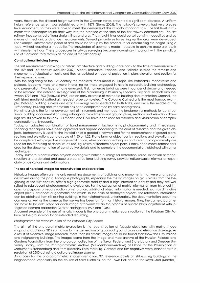
Figure 4: Results of automated photogrammetric surface measurements. From left: 3D model and horizontal
section of a sherd; 3D model of an architectural fragment; colored point cloud of the circular temple
Current developments
The complex manual photogrammetric evaluation methods increasingly are being replaced by automated procedures for image orientation and analysis. These developments are leading to an integration of classic photogrammetric techniques and procedures of digital image proceeding and computer vision. Today, adapted photogrammetric systems are available - especially for industrial and engineering applica-tions (automotive and production engineering, material testing) - that allow for the complete automation of recording and evaluation. Active photogrammetric systems, such as structured light or modulated light 3D

Proceedings of the Third International Congress on Construction History, May 2009 scanners, combine one camera with an adapted light projector for the automated capture of object surfaces with a very high point density. But most of these systems require adjusted and constant lighting conditions and they are designed for a special object size and form. Flexible photogrammetric systems allow for the automated recording of different object surfaces in the fields of architecture, archaeology, restoration and reconstruction (Henze et al 2006). The spectrum ranges from ar-chaeological small finds to architectural fragments and building decorations up to the recording of complete buildings (Fig. 4). Current developments aim at integration of range- and image-based scanning procedures within one re-cording system (Mulsow et al 2004). The surface geometry is detected with range based scanning, while pho-tographs provide continuous radiometric information.
APPLICATION OF SURVEYING AND PHOTOGRAMMETRIC TECHNIQUES
Historical examples of the application of classical surveying methods for construction
The application of traditional methods of surveying techniques will be illustrated by two examples from the 18th and 19th century.
Surveying methods for construction of the Frauenkirche Dresden (“Church of Our Lady”)
The Frauenkirche church in Dresden, one of the most important religious buildings of the German Baroque, was built from 1727 to 1742. The construction was planned and led by the architect George Baehr (1666-1738), who also had the idea of a stone dome with a diameter of approximately 26 meters. Frauenkirche was the widely visible town landmark of Dresden until its destruction on the 15th of February 1945. In connection with the reconstruction of the church from 1994 to 2005 numerous research activities on the historical construction were carried out. Even the historical methods of surveying were investigated. Numerous marked measurement points, which obviously had been used for the construction of the church, were found after the church site had been cleared of the wreckage (Remus 1996, Göpfert 1997). Also the perpendicular point of the main building part, which is also the intersection of the two main axes of the building, and the perpendicular point of the choir apse were excavated. Marking lines of the main building axes were found in the basement. Con-trol measurements that have been conducted in connection with the reconstruction of the church show that the positions of the found points differ only a few mm from the ideal dimensions of the planning (Remus 1996). From that it could be supposed that an angle measuring instrument was used at least for the determination of the main axes. However the original construction documents in the town archive of Dresden do not include any reference to the use of such a device (Remus 1996). In all likelihood the building main axes and the outline of the church were set out by means of measuring strings (Remus 1996). Right angles could be constructed with the so-called twelve-knot-cord based on the Pythagorean numbers 3-4-5. This numerical ratio has been known since ancient times and was used for surveying purposes up to the 20th century. In addition, construc-tions that began with a circle on paper were transmitted into reality with the use of measuring strings. In that way the setting-up of arcs, ellipses and triangular nets could been realized without problems using simple sur-veying equipment (Göpfert 1997). Based on the geometry of the church and the found perpendicular points, it can be assumed that the vertical position of the church was ensured or monitored by a long plumb line damped in an oil container, a method that was used in deformation monitoring until the end of the 20th cen-tury. For ensuring the horizontal level of the individual building planes, probably a simple mason`s level was used (Göpfert 1997), an instrument which had been known in Egypt 4000 years before. The example of the church Frauenkirche in Dresden shows that very precise measurement results can be achieved even with very simple methods based on solid geometric relationships.
Construction of the first railway lines
The surveying technologies of the 19th century interacted with a major engineering task- the construction of the first railroads in Europe. The first passenger railway line was opened in 1830 and led from Liverpool to Man-chester. The first public German railway, from Nuremberg to Fürth, followed in 1835. The planning and con-struction of the railway lines were accompanied by surveying activities right from the beginning. In the early years surveying was primarily the task of the railway engineers. State surveyors only carried out the cadastral surveys before starting the line routing (Siems 2005). The surveying technical tasks associated with the construc-tion of new railway lines were very comprehensive as they are still today. Maps on a scale range of 1:50 000 to 1:100 000 have been required for the route planning. While maps on a very small scale were available at that time almost everywhere in Germany, only a few countries such as Bavaria, Baden and Wuerttemberg had to-pographic maps in the required scale range (Siems 2005). A major problem of the former German states was the absence of uniform networks of triangulation, which are an important prerequisite for the realization of such large projects. Instead, existing maps had to be linked by means of identical map points, which often caused large discrepancies. If neither large-scale topographic maps nor cadastral maps were available, plane table surveys were executed. The principle of plane table surveying is the determination of the point po-sition by the intersection of directions from two known stations, so that the position of a point can be deter-mined by a pure angle measurement. Thus no distance measurements of great range, which at that time would have been very expensive, had to be carried out. A major challenge was to determine the terrain height. This task was especially important because rail locomotives could not surmount steep rises in the early
Proceedings of the Third International Congress on Construction History, May 2009
years. However, the different height systems in the German states presented a significant obstacle. A uniform height reference system was established only in 1879 (Siems 2005). The railway’s surveyors had very precise level equipment, so they were able to meet the demands of this critically important task. The first level instru-ments with telescopes found their way into the practice at the time of the first railway constructions. The first railway lines consisted of long straight lines and arcs. The straight lines could be set up with theodolites and by means of mechanical distance measurements. Several procedures for setting up the arcs were developed. For example, intermediate points of arcs could be set up by the procedure for determining rise height using a tape, without requiring a theodolite. The knowledge of geometry made it possible to achieve accurate results with simple methods. These procedures in railway surveying became increasingly important with the practical use of electronic total station at the end of the 20th century.
Constructional Building Survey
The first measurement drawings of historic architecture and buildings date back to the time of Renaissance in the 15th and 16th century (Schuller 2002). Alberti, Bramante, Raphael, and Palladio studied the remains and monuments of classical antiquity and they established orthogonal projection in plan, elevation and section for their representations. With the beginning of the 19th century the medieval monuments in Europe, like cathedrals, monasteries and palaces, became more and more interesting for those engaged in historic research, building archaeology and preservation. Two types of tasks emerged. First, numerous buildings were in danger of decay and needed to be restored. The detailed investigations of the Marienburg in Prussia by Friedrich Gilly and Friedrich Frick be-tween 1799 and 1803 (Salewski 1965) are an early example of methodic building documentation. Second, the unfinished medieval cathedrals needed to be completed. The Cologne Cathedral is the most famous exam-ple. Detailed building surveys and exact drawings were needed for both tasks, and since the middle of the 19th century, building documentation has been complemented by early photographs. Notwithstanding the further development of instruments and methods, the fundamental methods for construc-tional building documentation using orthogonal two-dimensional ground plans, sections and elevation draw-ings are still proven to this day. 3D models and CAD have been used for research and visualisation of complex constructions only recently. Today, an adapted combination of hand measurement, tacheometry, photogrammetry and, if necessary, scanning techniques have been approved and applied according to the aims of research and the given ob-jects. Tacheometry is used for the installation of a geodetic network and for the measurement of ground plans, sections and elevations up to a scale of 1:50 or 1:25. Plane laminar object parts in sections and elevations can be completed with projective image rectification, while scanning techniques and stereo photogrammetry are used for the recording of depth structured, figurative or freeform object parts. Finally, hand measurement is still used for the documentation of constructive details and to complete the documentation, obtained with other techniques. Today, numerous construction projects dealing with historic buildings for restoration, reuse, extension or recon-struction and a detailed and accurate constructional building survey provide indispensable information espe-cially on deviations and deformations.
The use of historical images for reconstruction and restoration
Historical images often are the only remaining documents of buildings and monuments that were changed or destroyed during the past. Analogue photographs, especially the metric images on glass plates from the be-ginning of the 20th century, offer a high geometric stability and a high information density and they are well suited to subsequent photogrammetric evaluation. For the extraction of metric information from historical im-ages for purposes of reconstruction or restoration, additional object information is needed, such as distinctive object points, distances or geometric constraints. In the case of destroyed objects, the reference information can be obtained from still existing buildings in the neighborhood. Unfortunately, the documentation about the cameras as well as the cameras themselves has been lost for most historic images. Thus, the camera parame-ters have to be calculated for each image afterwards within the process of bundle block adjustment with in-tegrated camera calibration (Wester-Ebbinghaus 1978 and 1985). A current example of the use of historic images is the photogrammetric reconstruction of the Potsdam City Pa-lace as the groundwork for an intended rebuilding.
Photogrammetric reconstruction of the Potsdam City Palace
The aim of the photogrammetric evaluation is the reconstruction of façade elevations with metric image maps and additional 3D information for the generation of graphical ground plans and elevation drawings. As a result of extensive image research, more than 80 historic images could be found that show the City Palace and neighboring buildings. The images come from the image and map archive of the Prussian Palaces and Gardens Foundation, from the photograph collection of the Saxon Federal and State Library and Dresden Uni-versity Library, from the Photogrammetric Archive (Meydenbauer-Archive) at Office for the Preservation of Monuments Brandenburg and from Bildarchiv Foto Marburg. Contact and film negatives were scanned with a resolution of 2500 dpi using a calibrated image scanner. As a basis for the photogrammetric image orientation, 3D reference points on still existing buildings in the neighborhood, especially on the church of Saint Nicholas, on the Town Hall and on the Royal Stud (Marstall),

Proceedings of the Third International Congress on Construction History, May 2009 were measured using tacheometry. For an integration of the current archaeological work on the foundation of the palace, all measurements were linked to the official geodetic system. Additional reference information was obtained from dimensional ground plans from 1910 and 1960. First, approximated values for the camera parameters and for the image orientation were estimated by calcu-lation of spatial resection for single images. For this purpose, the reference points and additional object ge-ometries were defined in the images. The images were evaluated and selected on the basis of the image quality (resolution, sharpness, distortion), the geometric configuration (camera position, orientation, captured object area) and the orientation accuracy. At least 39 images from a total of 62 images were used for single image orientation and for further use. In a second step, the parameters of inner and outer orientation of the remaining images were estimated simul-taneously with bundle block adjustment. For this, additional tie points and geometries (perpendicular lines) were measured within all images. Besides the estimation of camera and orientation parameters for all images, the results of bundle block adjustment allow an analysis of the actual accuracy of the photogrammetric eval-uation. The accuracy depends on the geometric configuration and on the geometric and radiometric image quality and it can vary over discrete façade regions. The maximum point error for the north, west and south façade reaches a maximum of 2-3 cm and for the east façade a maximum point error of 3-8 cm. The oriented images were used to estimate additional reference points for image rectification of single object areas. Whenever possible, only images with an adequate resolution and with a camera axis perpendicular to the façade were used for image rectification. Finally, the single-image rectifications were assembled to an image map for the whole façade on a scale of 1:50 (Fig. 5).
Figure 5: Rectified image map of the south façade of Potsdam City Palace using historical images from the
Meydenbauer-Archive, fokus GmbH Leipzig
CONCLUSIONS
Surveying technologies always have been essential for the construction as well as for the documentation of buildings. Classical – even very simple - devices like measuring strings were used until the middle of the 19th century. Nevertheless specialists achieved a very high degree of accuracy using even these simple methods based on a sound knowledge of mathematical relations. The development of surveying instruments has been influenced during this time mainly by astronomy, land surveying and military applications. Meydenbauer de-veloped photogrammetry as an independent method for building documentation 150 years ago. At the same time optical surveying instruments became more and more important for engineering surveying, especially for railway construction. The advantages of modern electronic instruments, which were developed in the second half of the 20th century, are a short measuring time for achieving precise results and ease of use. Today the engineer can choose among several technologies and instruments. The spectrum ranges from simple hand measurements to tacheometric measurements up to automated recordings using photogrammetry or laser scanning. The decision as to which method is the most suitable depends on the surveying problem and the requirements of accuracy and it should be discussed in accordance with users and geodesists.
REFERENCES
Atkinson, K.B., 1996: Close-range Photogrammetry and Machine Vision, WhittlesPublishing, UK. Bräuer-Burchardt, C.; Voss, K., 2001: Facade Reconstruction of Destroyed Buildings Using Historical Photo-
graphs, In: Jörg Albertz (ed.): Proc. of the XVIII. International Symposium CIPA 2001, Sep. 18 - 21, Potsdam, Germany, pp. 543-550.
Brown, D.C., 1958: A solution to the general problem of multi station analytical stereo-triangulation, RCA Tech-nical Report No. 43.
Brown, D. C., 1971: Close-range camera calibration, Photogrammetric Engineering Vol. 37(8), pp. 855-866. Bührer, T.; Grün, A.; Zhang, L.; Fraser, C.; Rüther, H., 2001: Photogrammetric Reconstruction and 3D Visualization
of Bet Gorgis, a Rock-hewn Church in Ethiopia, In: Jörg Albertz (ed.): Proc. of the XVIII. International Sympo-sium CIPA 2001, Sep. 18 - 21, Potsdam, Germany, pp. 338-344.
Deumlich, F.; Staiger, R., 2002: Instrumentenkunde der Vermessungstechnik. Wichmann Verlag, Heidelberg.
Proceedings of the Third International Congress on Construction History, May 2009
Eckstein, G. (ed.), 2003: Empfehlungen für Baudokumentationen, Arbeitsheft 7, Konrad Theiss Verlag, Stuttgart. Förstner, W., 1982: On the Geometric Precision of Digital Correlation, In: Intern. Arch. of Photogrammetry and
Remote Sensing, Helsinki, Vol. 24, No. 3, pp. 176-189. Göpfert, G., 1997: Untersuchungen zu den Vermessungstechnologien an der Dresdner Frauenkirche. Study pro-
ject Geodätisches Institut TU Dresden, unpublished. Grimm, A, 1977: 120 Jahre Photogrammetrie in Deutschland – Das Tagebuch von Albrecht Meydenbauer.
Deutsches Museum. Abhandlungen und Berichte, 45. Jahrgang, Heft 2, München. Grün, A., 1985: Adaptive least squares correlation: A powerful image matching technique, South African Jour-
nal of Photogrammetry, Remote Sensing and Cartography Vol. 14(No. 3), pp. 175-187. Grün, A., 1994: Von Meydenbauer zur Megaplus: Die Architekturphotogrammetrie im Spiegel der technischen
Entwicklung, Zeitschrift für Photogrammetrie und Fernerkundung 2/1994, pp. 41-56. Hemmleb, M, 1999: Digital Rectification of historical images, In: Proc. of the XVII CIPA Symposium, Mapping
and Preservation for the New Millenium, Olinda, Brazil. Hemmleb, M.; Siedler, G.; Sacher, G., 2001: Digitale Bildentzerrungen und -abwicklungen für die Anwendung in
Denkmalpflege, Bauforschung und Restaurierung, In: U. Weferling; K. Heine; U. Wulf (eds.): Von Handaufmaß bis HighTech - Aufnahmeverfahren in der historischen Bauforschung, Verlag Philipp von Zabern, pp. 74-82.
Heine, K.; Brasse, Ch.; Wulf, U., 2006: WWW-Based Building Information System for “Domus Severiana” Palace at Palatine in Rome by Open Source Software. In: Ioannides, M., Arnold, D., Niccolucci, F., Mania, K. (eds): Proc. of th joint event VAST 2006, Nikosia, Eurographics Association, Aire-la-Ville, pp. 75-82.
Henning, G. K., 1995: Der Verlauf der Bautätigkeit an der Frauenkirche in den Jahren 1724-1727. In: Die Dresd-ner Frauenkirche, Annual 1995, Verlag Hermann Böhlaus Weimar, pp 85-110.
Henze, F.; Lehmann, H., in prep.: Analysis of historical maps and images for research on urban development of Baalbek/Lebanon since Roman Antiquity, In: Proc. of the conference: Historic maps and imagery for mod-ern scientific applications, November 28th - 30th, 2008, Bern (CH).
Henze, F.; Siedler, G.; Vetter, S., 2006: Integration of Digital Image Analysis for Automated Measurements into a Photogrammetric Stereo Evaluation System. In: H.-G. Maas, D. Schneider (eds): Proc. of the ISPRS Commis-sion V Symposium 'Image Engineering and Vision Metrology', Dresden, Germany, Sep. 25-27, Vol. XXXVI, PART 5
Henze, F.; Wulf-Rheidt, U.; Schneider D.; Bienert, A., 2005: Photogrammetric and Geodetic Documentation Me-thods at St. Petri Cathedral, Bautzen, Proc. of the XX. CIPA-Symposium, Turin, 26. Sep.-01. Oct., pp. 366 – 371.
van den Heuvel, F. A., 2001: Reconstruction from a Single Architectural Image from the Meydenbauer Archive, In: Jörg Albertz (ed.): Proc. of the XVIII. International Symposium CIPA 2001, Sep. 18 - 21, Potsdam, Germany, pp. 699-706.
Junius, H. (ed.), 1987: Ingenieurvermessung von der Antike bis zur Neuzeit. Konrad Wittwer Verlag, Stuttgart. Kahmen, H.; Faig, W., 1988: Surveying. Walter de Gruyter, Berlin, New York. Luhmann, T., 2000: Nahbereichsphotogrammetrie: Grundlagen, Methoden und Anwendungen, Herbert Wich-
mann Verlag, Heidelberg. Meydenbauer, A., 1911: Handbuch der Messbildkunst in Anwendung auf Baudenkmäler und Reiseaufnahmen.
Verlag W. Knapp, Halle a. S. Mulsow, C.; Schneider, D.; Ullrich, A.; Studnicka, N., 2004: Untersuchungen zur Genauigkeit eines integrierten
terrestrischen Laserscanner-Kamerasystems. In: Luhmann, T. (ed.): Photogrammetrie, Laserscanning, Opti-sche 3D-Messtechnik - Beiträge der Oldenburger 3D-Tage 2004. pp. 108-113, Wichmann Verlag, Heidelberg.
Pulfrich, C., 1923: Die Stereoskopie im Dienste der Photometrie und Pyrometrie, Verlag Julius Springer, Berlin. Regensburger, K., 1990: Photogrammetrie - Anwendungen in Wissenschaft und Technik, VEB Verlag für Bauwe-
sen, Berlin. Remus, T., 1996: Technologische Betrachtungen beim Bau der Frauenkirche zu Dresden. In: Die Dresdner Frau-
enkirche, Annual 1996, Verlag Hermann Böhlaus Weimar, pp 203-212. Salewski, W. (ed.), 1965: Gilly, F. und Frick, F.: Schloß Marienburg in Preußen. Das Ansichtenwerk. In Lieferungen
erschienen von 1799 bis 1803, Faksimile, Galtgarben Verlag, Düsseldorf. Schäfer, H., 2001: Zustands- und Materialkartierung auf der Basis photogrammetrisch erstellter Planunterlagen
am südlichen Chorturm des Ulmer Münsters, In: Eckstein (ed.), G.: Vom Messbild zur Bauanalyse - 25 Jahre Photogrammetrie im Landesdenkmalamt Baden-Württemberg, Konrad Theiss Verlag, pp. 105-112.
Schmid, H., 1958: Eine allgemeine analytische Lösung für die Aufgabe der Photogrammetrie, Bildmessung und Luftbildwesen, 4/1958, pp. 103-112.
Schuller, M., 2002: Building archaeology. ICOMOS, München. Siems, E., 2005: Erste Eisenbahnen – nicht ohne Feldvermesser. In: Der Eisenbahningenieur (56) 9/2005, DVV
Media Group Eurailpress, Hamburg, pp. 70-76 Siems, E., 2008: Vermessungsarbeiten für die ersten Eisenbahnstrecken in Niedersachsen. In: Der Eisenbahnin-
genieur 08/2008, DVV Media Group Eurailpress, Hamburg, pp. 48-54. Szangolies, K. (ed.), 1986: Kompendium Photogrammetrie Band XVIII, Akademische Verlagsgesellschaft Geest
& Portig, Leipzig. Wester-Ebbinghaus, W., 1978: Photogrammetrische Punktbestimmung durch Bündelausgleichung zur allseitigen
Erfassung eines räumlichen Objektes. Bildmessung und Luftbildwesen, 46(6), pp. 198-204. Wester-Ebbinghaus, W. 1985: Bündeltriangulation mit gemeinsamer Ausgleichung photogrammetrischer und
geodätischer Beobachtungen. Zeitschrift für Vermessungswesen 3/1985, pp. 101 - 111. Wiedemann, A.; Hemmleb, M.; Albertz, J., 2000: Reconstruction of historical buildings based on images from
the Meydenbauer archives, IAPRS Vol. XXXIII, B5/2, pp. 887-893. Wulf-Rheidt, U.; Henze, F., 2008: Die Fassadenkartierung - Von der photogrammetrischen Aufnahme zum Be-
fundplan, In: Haseley, A; Stiehler, A. (eds.): Der Dom St. Petri in Bautzen: Projektbericht - Untersuchungen zur nachhaltigen Instandsetzung, TUDpress Verlag der Wissenschaften Dresden, , pp. 45-52.