chapter 5 : part i the pinch (heat integrations)€¦ · a heat recovery/integration problem...
TRANSCRIPT

CHAPTER 5 : Part I THE PINCH
(HEAT INTEGRATIONS)
1

Learning Outcomes
After studying this topic, participants should be able to: • To determine Maximum Energy Requirement (MER) targets; i.e
to compute the minimum usage of heating and cooling utilities when exchanging heat between the hot and cold stream in a process.
• To design a grid/network to meet the MER targets; i.e to position heat exchanger in a network, assuming overall heat-transfer coefficients by applying the closest-approach temperature difference (the Pinch in Part I) and the Composite Curve (Part II).
2

• This topic will cover: – The “pinch”
– The design of Heat Exchanger Network (HEN) to meet Maximum
Energy Recovery (MER) targets.
– The use of the “Pinch”, Composite Curve, and Problem Table to
systematically compute MER targets.
• Chapter 5: Part I: The Pinch – How to do it?
Given data on hot and cold streams, you should be able to:
– Compute the pinch temperatures?
– Compute MER targets?
– Design a simple grid and HEN to meet the MER targets?

• Early pioneers:
– Rudd@Wisconsin (1968)
– Hohmann@USC (1971)
• Central figure:
– Linnhoff@ICI/UMIST (1978)
– Currently: President, Linnhoff-March
• Recommended texts:
– Seider, Seader and Lewin (1999): Process Design Principles,
Wiley and Sons, NY
– Linnhoff et al. (1982): A User Guide on Process Integration for the
Efficient Use of Energy, I. Chem. E., London
• Most up-to-date review:
– Gundersen, T. and Naess, L. (1988): “The Synthesis of Cost
Optimal Heat Exchanger Networks: An Industrial Review of the
State of the Art”, Comp. Chem. Eng., 12(6), 503-530
A Short Bibliography...

Introduction - Capital vs. Energy
• The design of HEN for heat integration deals with the following problem:
Given:
• Number of hot streams (NH), with given heat capacity flowrate (C=mCp),
each have to be cooled from supply temperature THS (supply temperature hot stream) to
targets THT (target temperature hot stream)
• Number of cold streams (NC), with given heat capacity flowrate (C),
each have to be heated from supply temperature TCS (supply temperature cold stream)
to targets TCT (target temperature cold stream)
Design:
An optimum network of heat exchangers, connecting between the hot and cold
streams and between the streams and cold/hot utilities (furnace, hot-oil, steam,
cooling water or refrigerant, depending on the required duty temperature).
What is optimal?
Implies a trade-off between Cost of equipment (Capital Cost) and Energy Cost
(Operation costs).

6
A Distillation Train –
Design Without Process/Heat Integration
KEY
NO. OF HEATERS = 3
NO. OF COOLERS = 2
Inspect scope for energy saving through heat recovery/integration...
A stream that needs
heating
A stream that needs
cooling

A Heat Recovery/Integration Problem
Consider heat exchange between the process streams to save hot utility (steam) and cold utility (cooling water).
Tin
40°C
Tout
130°C
Steam is used for heating
Tin
200°C
Tout
50°C
Cooling water is used for cooling
Stream that needs heating - A “cold” stream (heat sink)
Stream that needs cooling - A “hot” stream (heat source)
Process stream

Some Definitions
T
HH
TS
TT
T
TS = Stream supply temperature (oC)
TT = Stream target temperature (oC)
H = Stream enthalpy (MW)
C = mCp (MW/ oC)
= Heat capacity flowrate (MW/ oC)
m = Stream flowrate Cp = specific heat capacity
H = mCpΔT = mCP (Tt - Ts)
Note: If mCp is constant, the line is linear.
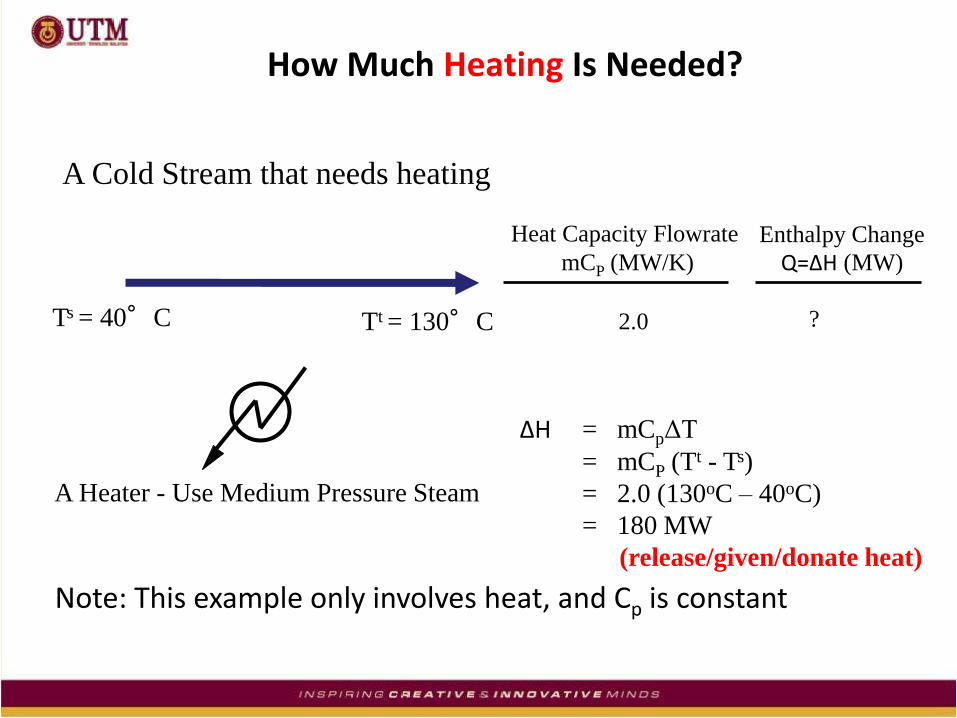
How Much Heating Is Needed?
A Cold Stream that needs heating
Heat Capacity Flowrate
mCP (MW/K)
Enthalpy Change
Q=ΔH (MW)
2.0 ?
ΔH = mCpΔT
= mCP (Tt - Ts)
= 2.0 (130oC – 40oC)
= 180 MW
(release/given/donate heat)
A Heater - Use Medium Pressure Steam
Tt = 130°C Ts = 40°C
Note: This example only involves heat, and Cp is constant

How Much Cooling Is Needed?
A Hot Stream that needs cooling
A Cooler - Use Cooling Water
Ts = 200°C Tt = 50°C
Heat Capacity Flowrate
mCP (MW/K)
Enthalpy Change
Q=ΔH (MW)
1.0 ?
Q = mCpΔT
= mCP (Tt - Ts)
= 1.0 (50°C - 200 °C)
= -150 MW
(adsorbs/receive/require heat)

Heat Exchange Between Process Streams
83% Saving On Steam
100% Saving On Cooling
Water
Before Integration
180 MW
150MW
After Integration
30 MW
Stream Number
Stream Type mCP
(MW/K) Ts
( oC )
1 Cold 40 130 2.0 180
2 Hot 200 50 1.0 -150
Q (MW)
Tt
( oC )
A process to process heat exchanger

Distillation Train – Design With Process/Heat Integration
PROCESS INTEGRATION RESULTS IN CAPITAL AND ENERGY COST SAVINGS!
KEY
NO. OF HEATERS = 1
NO. OF COOLERS = 0

but, in the industry...
Many Hot Streams
Many Cold Streams

14
Heat Exchanger Network
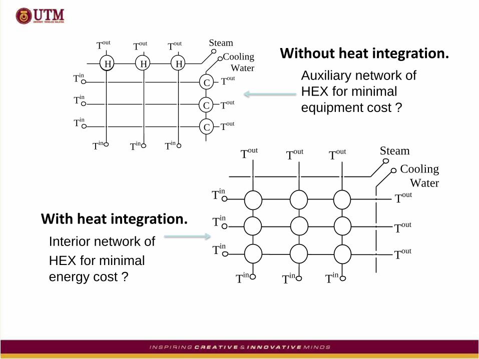
Interior network of
HEX for minimal
energy cost ?
Auxiliary network of
HEX for minimal
equipment cost ?
H H H
C
C
C
Cooling
Water
Steam
Tin
Tin
Tin
Tin
Tin T
in
Tout
Tout
Tout
Tout
Tout
Tout
Cooling
Water
Steam
Tin
Tin
Tin
Tin
Tin T
in
Tout
Tout
Tout
Tout
Tout
Tout
Without heat integration.
With heat integration.

Numerical Example
Design II: Area= 13.3
smaller for HEN
Design I: Area= 20.4
greater for HEN
Cooling
Water (90-110oF)
Cooling
Water (90-110oF)
Steam (400oF)
300o
300o
500
500
150o
200o
200o
150o
150o
200o
200o
200o
200o
100100
100100
100100
300o
300o
300o
300o
500
500 50
050
0
CP = 1.0CP = 1.0
CP = 1.0CP = 1.0
CP = 1.0CP = 1.0
CP = 1.0 CP = 1.0 CP = 1.0
100 100 100
300o
300o
500
500
150o
200o
200o
150o
150o
200o
200o
200o
200o
300o
300o
300o
300o
500
500 50
050
0
CP = 1.0CP = 1.0
CP = 1.0CP = 1.0
CP = 1.0CP = 1.0
CP = 1.0 CP = 1.0 CP = 1.0
100
100
100

To achieve maximum energy recovery (MER)
through heat integration requires a systematic
approach in designing complex HEN, so we need to apply:
Pinch Technology!!

Pinch Technology
Now, design with targets
• HEAT RECOVERY PROBLEM
• SET TARGETS (Energy and Capital)
• DESIGN HEN (based on these targets)
Traditionally, design “As We Go” in designing:
• HEAT RECOVERY PROBLEM
• DESIGN HEN only
Heat Exchanger Network (HEN) Design;

Pinch Design Targets
Targets Set Ahead of Design…..
(Use 1st Law of Thermodynamics)
What are the:
• Minimum Heating Requirement (Usually Steam Rate)
• Minimum Cooling Requirement (Usually Cooling Water Rate)
• Minimum Number of Units/Equipment?

Pinch Application - Fine Chemical Front End Design
A traditional design (Without MER targets),
FL
AS
H
RECYCLE
PRODUCT
REACTOR
FEED 3 2
1 = 1722 MW steam
cooling water
= 654 MW
number of unit = 6
4
5 6
Stream Mixing

21
FL
AS
H
RECYCLE
PRODUCT
REACTOR
FEED 3
2
1
Pinch design (with MER targets),
= 1068 MW steam
cooling water
= 0 MW
number of unit = 4
Targets achieved
4

Consider the following utilities streams
C1 120oF 235oF
C2 180oF
240oF
H1
H2
260oF 160oF
250oF 130oF
Lets say we know mCp for each stream, so;

Stream Ts(oF) Tt(oF) mCp
Q(104Btu/hr)
104 Btu/hr.oF
C1 120 235 2 230
C2 180 240 4 240
H1 260 160 3 300
H2 250 130 1.5 180
An example for C1, mCp=2x10⁴ Btu/hr.oF thus, Q= mCp ΔT=(2x10⁴ )x (235-120) = 230x104 Btu/hr
No heat integration. Heat required by each streams,

This example only involves sensible/practical heat with constant Cp and ΔTmin = 10oF
1st Law of Thermodynamics (conservation of energy), Q=ΣQH-ΣQC=[(300+180)-(230+240)]x104Btu/hr=10x104Btu/hr So, after heat integration and provided no violation/ruin of 2nd Law of Thermodynamics, we still need 10x104Btu/hr to cool the hot streams. However, this this value is usually not the Minimum Energy Required (MER).

One Possible HEN with heat integration
6 HEX (3 interior HEX and 3 auxiliary HEX) Qsteam = 30+27.5 = 57.5x10⁴Btu/hr QCW = 67.5x10⁴Btu/hr Note, Q = Qsteam-QCW
=10x104Btu/hr So, does not violate 1st Law.

Questions: How do these QH and QC compare with MER targets?

Process Energy Targets
Process energy targets or maximum energy recovery (MER) (hot (steam) and cold (cooling water) utilities requirements) can be obtained from,
1. Problem Table Algorithm or Temperature-Interval Method
• process heat surpluses and deficits within
some specified temperature intervals-The PINCH
2. Graphical Method (Composite Curve Method)
• cumulative process heat availability (surplus)
• cumulative process heat requirement (deficit)

3. Using formulation/solution of linear programming
Here, we will cover Methods 1 and 2.

29
Let’s revisit our previous example and apply Method 1- The Pinch

Stream Ts(oF) Ts(oF) Tt(oF) Tt(oF)
adjusted adjusted
C1 120 120 235 235
C2 180 180 240 240
H1 260 250 160 150
H2 250 240 130 120
Step 1: Randomly adjust Ts and Tt using ΔTmin. This is to avoid temperature violation/ruin of ΔTmin in the subsequent calculations. Here, adjustment is by reducing only the hot streams temperature by ΔTmin=10oF
Method 1 : In total with 9 steps to be discussed . . . .

Step 2: Rank all the adjusted temperatures and eliminate duplicates, and create intervals, 250=T0 240=T1 Interval 1=T0-T1=250-240 240 235=T2 Interval 2=T1-T2=240-235 180=T3 Interval 3=T2-T3=235-180 150=T4 Interval 4=T3-T4=180-150 120=T5 Interval 5=T4-T5=150-120
120
Stream Ts(oF) Ts(oF) Tt(oF) Tt(oF)
adjusted adjusted
C1 120 120 235 235
C2 180 180 240 240
H1 260 250 160 150
H2 250 240 130 120

Streams in this interval Interval 1=T0-T1=250-240 Only H1 Interval 2=T1-T2=240-235 H1, H2,C2 Interval 3=T2-T3=235-180 H1,H2,C2,C1 Interval 4=T3-T4=180-150 H1,H2,C1 Interval 5=T4-T5=150-120 H2,C1
250oF
240
235
180
150
120
C1
C2
H1
H2
Step 3: Identify streams within each interval.

Interval,i ΔT (ΣCh-ΣCc) ΔH
104Btu/hr.oF 104Btu/hr
1 (250-240) 10 3 30
2 (240-235) 5 3+1.5-4=0.5 2.5
3 (235-180) 55 3+1.5-4-2=-1.5 -82.5
4 (180-150) 30 3+1.5-2=2.5 75
5 (150-120) 30 1.5-2=-0.5 -15
Step 4: Calculate enthalpy difference between heat removed from hot streams and heat absorbed by the cold streams across each interval using, ΔH=ΣΔHh -ΣΔHc =(ΣCh-ΣCc)ΔT

Step 5: Create a flow of temperature intervals within which the enthalpy differences (ΔHi) are calculated. This is to show energy flow between intervals. For interval 1, no energy from hot utilities is assumed to enter this interval initially, so Qsteam= 0 for the initial pass. Calculate a residual (R) using, Ri=ΔHi+(Energy entering the interval). e.g. R1=ΔH1+Qsteam
R2=ΔH2+R1

Step 6: Set Qsteam equal the largest negative residual i.e. add energy at T>250oF using low pressure steam This is to satisfy 2nd Law, all the negative residuals must be removed i.e. heat can’t flow from low to high T. Recalculate residuals for each interval.

36
Step 7: Determine the pinch T and MER targets Notice now that no energy flow between interval 3 and 4 i.e. R3=0. This is referred to as the pinch. The pinch temperature is 180oF (cold stream) and 190oF (Hot stream) (by added for hot stream i.e. ΔTmin=10oF) So, to maintain minimum utilities, no energy is allowed to flow across the pinch. Also cold utility duty is QCW is 60x104 Btu/hr Note: Qsteam – QCW= (50-60)= -10x104 Btu/hr
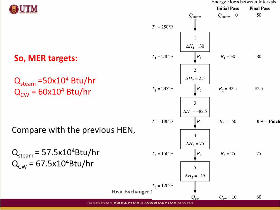
Heat Exchanger Network
So, MER targets: Qsteam =50x104 Btu/hr QCW = 60x104 Btu/hr
Compare with the previous HEN, Qsteam = 57.5x10⁴Btu/hr QCW = 67.5x10⁴Btu/hr

To maintain MER targets (i.e. minimum utilities), 2 separate HENs must be designed. One on the hot side and one on the cold side of the pinch.
Hot side Cold side
Stream Ts(oF) Ts(oF) Tt(oF) Tt(oF)
adjusted adjusted
C1 120 120 235 235
C2 180 180 240 240
H1 260 250 160 150
H2 250 240 130 120

An Example of cooling & heating loads for each interval at MERs
Cooling (Hot Stream) Heating (Cold Stream)
Temperature *mCp *Q Temperature *mCp *Q
Interval, i Range (oF) Btu/hr.oF
Btu/hr Range (oF) Btu/hr.oF Btu/hr
1 250-260 3 30 240-250 0 0
2 240-250 3+1.5 22.5 235-240 4 20
3 190-240 3+1.5 247.5 180-235 4+2 330
4 160-190 3+1.5 135 150-180 2 60
5 130-160 1.5 45 120-150 2 60
Cum. Q 480 Cum. Q 470
*Multiply by 104
Stream Ts(oF) Ts(oF) Tt(oF) Tt(oF)
adjusted adjusted
C1 120 120 235 235
C2 180 180 240 240
H1 260 250 160 150
H2 250 240 130 120

Design HENs for maximum energy recovery
Now that we know the pinch temperatures and the minimum hot & cold utilities requirement, let’s design HENs to achieve these targets. Here we will only use method of stream matching at the pinch by Linnhoff and Hindmarsh. This method starts with the understanding of basic energy balance between the hot stream and the cold stream within a HEX.

11
:above equationsboth Substract
or
or
0,>QFor
1 2
ch
hc
ch
cihocohicicohohi
c
cicocicocc
h
hohihohihh
CC
CCQTT
CCQTTTTTTTT
C
QTTTTCHQ
C
QTTTTCHQ

ch
hc
ch
hc
CC
CCQTT
or
CC
CCQTT
min2
min2
Consider HEX on the hot side of the pinch where, ΔT1= ΔTmin (i.e. at the pinch) so,
To ensure ΔT2 ≥ ΔTmin, (Cc-Ch) ≥ 0 or Cc≥ Ch Otherwise the ΔT2 <Δtmin (that not valid)
Hot side
Stream Ts(oF) Ts(oF) Tt(oF) Tt(oF)
adjusted Adjusted
C1 120 120 235 235
C2 180 180 240 240
H1 260 250 160 150
H2 250 240 130 120

43
Consider HEX on the cold side of the pinch where, ΔT2= ΔTmin (i.e. at the pinch) so,
To ensure ΔT1 ≥ΔTmin, (Cc-Ch) ≤ 0 or Ch≥ Cc otherwise the ΔT1 <Δtmin (that not valid)
Cold side

Revisit our previous example
Hot side Cold side Let’s start designing the HEN on the hot side starting at pinch (Cc≥ Ch ) and working outwards. Matching H1: Since CH1=3, the only choice of cold stream is C2 where CC2 = 4. ΔH for H1: 3(260-190)=210 ΔH for C2: 4(240-180)=240 So, the heat duty of 210; from C2 (240) will provide enough cooling requirement for H1 (210). With resulting To = 232.5oF for C2. i.e. 4(To-180)=210

Hot side Cold side Note: Cc≥ Ch Matching H2: Since CH2=1.5, we could use stream C1 where CC1 = 2. ΔH for H2: 1.5(250-190)=90 ΔH for C1: 2(235-180)=110 So, the heat duty of 90; from C1 (110) will provide enough cooling requirement for H2 (90), with resulting To = 225oF for C1. i.e. 2(To-180)=90

Hot side Cold side Add hot utilities: To bring C1 and C2 to its target T we use utility heaters with heat duty of 20 and 30 respectively. Note: 2(235-225)=20 The total Qh=50 (Qsteam) matches the MER heating target. Link the streams with vertical line and number the HEX.
Hot side
Hot side Cold side
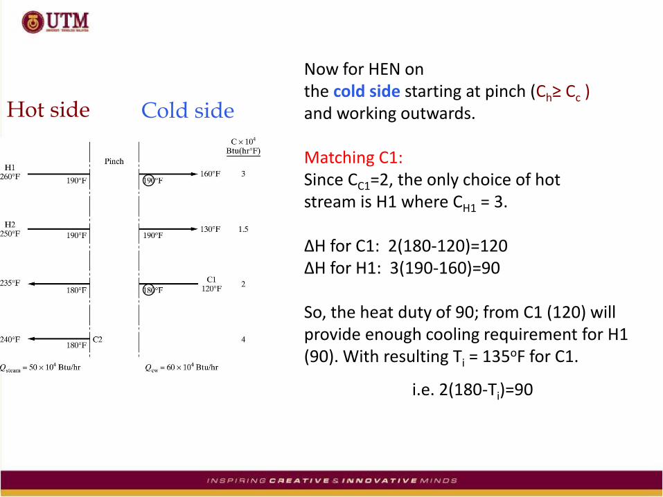
Now for HEN on the cold side starting at pinch (Ch≥ Cc ) and working outwards. Matching C1: Since CC1=2, the only choice of hot stream is H1 where CH1 = 3. ΔH for C1: 2(180-120)=120 ΔH for H1: 3(190-160)=90 So, the heat duty of 90; from C1 (120) will provide enough cooling requirement for H1 (90). With resulting Ti = 135oF for C1.
i.e. 2(180-Ti)=90

Hot side Cold side
Now the extra duty (30) on C1 can be Used to cool H2: With resulting To = 170oF for H2. i.e. 1.5(190-To)=30 Note: the pairing rule (i.e. Ch≥ Cc ) only apply at the pinch (T=180oC).

Cold side Add cold utilities: To bring H2 to its target T=130oF we use a utility cooler with heat duty of 60. Note: 1.5(170-130)=60 The Qc=60 (Qcw) matches the MER cooling target. Link the streams with vertical line and number the HEX. Stream matching is complete!

Cold side
Complete stream matching at MER

HEN after stream matching at MER
Min. duties with 7 HEXs…… (4 interior HEX and 3 auxiliary HEX)

THANK YOU
52
Or Compare…….
Heat Exchanger Network (HEN) Extra duties with only 6 HEXs….

53
What next?
Need to investigate the trade-off between capital and operating costs………. Also see example 10.7 Note: For system involving phase change and variable heat capacity see example 10.5. See section 10.4 on how to minimize number of HEXs (eliminate small HEXs with slight increase in utilities)

54
Tutorial/Assignment
The following figure is proposed for HEN between four streams. Determine if the network has the minimum utility requirements. If not, design a network with the minimum utility requirements. Use ΔTmin=20oC for all HEX.
H2(C=8KW/oC)
C2 (C=3KW/oC)
C1 (C=2.5KW/oC)
H1 (C=2.5KW/oC)
2 1
3 5 4
90oC 150oC
100oC 25oC 70oC
125oC
60oC
73.125oC 114C
20oC 74oC
60oC
127.5KW
90KW 135KW
105KW 135KW
CW Steam

THANK YOU
55