zigbee baseband verification library
TRANSCRIPT


SystemVue - ZigBee Baseband Verification Library
1
SystemVue 2010.072010
ZigBee Baseband Verification Library

SystemVue - ZigBee Baseband Verification Library
2
© Agilent Technologies, Inc. 2000-2010395 Page Mill Road, Palo Alto, CA 94304 U.S.A.No part of this manual may be reproduced in any form or by any means (includingelectronic storage and retrieval or translation into a foreign language) without prioragreement and written consent from Agilent Technologies, Inc. as governed by UnitedStates and international copyright laws.
Acknowledgments Mentor Graphics is a trademark of Mentor Graphics Corporation inthe U.S. and other countries. Microsoft®, Windows®, MS Windows®, Windows NT®, andMS-DOS® are U.S. registered trademarks of Microsoft Corporation. Pentium® is a U.S.registered trademark of Intel Corporation. PostScript® and Acrobat® are trademarks ofAdobe Systems Incorporated. UNIX® is a registered trademark of the Open Group. Java™is a U.S. trademark of Sun Microsystems, Inc. SystemC® is a registered trademark ofOpen SystemC Initiative, Inc. in the United States and other countries and is used withpermission. MATLAB® is a U.S. registered trademark of The Math Works, Inc.. HiSIM2source code, and all copyrights, trade secrets or other intellectual property rights in and tothe source code in its entirety, is owned by Hiroshima University and STARC.
Errata The SystemVue product may contain references to "HP" or "HPEESOF" such as infile names and directory names. The business entity formerly known as "HP EEsof" is nowpart of Agilent Technologies and is known as "Agilent EEsof". To avoid broken functionalityand to maintain backward compatibility for our customers, we did not change all thenames and labels that contain "HP" or "HPEESOF" references.
Warranty The material contained in this document is provided "as is", and is subject tobeing changed, without notice, in future editions. Further, to the maximum extentpermitted by applicable law, Agilent disclaims all warranties, either express or implied,with regard to this manual and any information contained herein, including but not limitedto the implied warranties of merchantability and fitness for a particular purpose. Agilentshall not be liable for errors or for incidental or consequential damages in connection withthe furnishing, use, or performance of this document or of any information containedherein. Should Agilent and the user have a separate written agreement with warrantyterms covering the material in this document that conflict with these terms, the warrantyterms in the separate agreement shall control.
Technology Licenses The hardware and/or software described in this document arefurnished under a license and may be used or copied only in accordance with the terms ofsuch license.
Portions of this product is derivative work based on the University of California PtolemySoftware System.
In no event shall the University of California be liable to any party for direct, indirect,special, incidental, or consequential damages arising out of the use of this software and itsdocumentation, even if the University of California has been advised of the possibility ofsuch damage.
The University of California specifically disclaims any warranties, including, but not limitedto, the implied warranties of merchantability and fitness for a particular purpose. Thesoftware provided hereunder is on an "as is" basis and the University of California has noobligation to provide maintenance, support, updates, enhancements, or modifications.
Portions of this product include code developed at the University of Maryland, for theseportions the following notice applies.
In no event shall the University of Maryland be liable to any party for direct, indirect,special, incidental, or consequential damages arising out of the use of this software and itsdocumentation, even if the University of Maryland has been advised of the possibility ofsuch damage.
The University of Maryland specifically disclaims any warranties, including, but not limitedto, the implied warranties of merchantability and fitness for a particular purpose. thesoftware provided hereunder is on an "as is" basis, and the University of Maryland has noobligation to provide maintenance, support, updates, enhancements, or modifications.
Portions of this product include the SystemC software licensed under Open Source terms,which are available for download at http://systemc.org/ . This software is redistributed byAgilent. The Contributors of the SystemC software provide this software "as is" and offerno warranty of any kind, express or implied, including without limitation warranties orconditions or title and non-infringement, and implied warranties or conditionsmerchantability and fitness for a particular purpose. Contributors shall not be liable forany damages of any kind including without limitation direct, indirect, special, incidentaland consequential damages, such as lost profits. Any provisions that differ from thisdisclaimer are offered by Agilent only.

SystemVue - ZigBee Baseband Verification Library
3
With respect to the portion of the Licensed Materials that describes the software andprovides instructions concerning its operation and related matters, "use" includes the rightto download and print such materials solely for the purpose described above.
Restricted Rights Legend If software is for use in the performance of a U.S.Government prime contract or subcontract, Software is delivered and licensed as"Commercial computer software" as defined in DFAR 252.227-7014 (June 1995), or as a"commercial item" as defined in FAR 2.101(a) or as "Restricted computer software" asdefined in FAR 52.227-19 (June 1987) or any equivalent agency regulation or contractclause. Use, duplication or disclosure of Software is subject to Agilent Technologies´standard commercial license terms, and non-DOD Departments and Agencies of the U.S.Government will receive no greater than Restricted Rights as defined in FAR 52.227-19(c)(1-2) (June 1987). U.S. Government users will receive no greater than LimitedRights as defined in FAR 52.227-14 (June 1987) or DFAR 252.227-7015 (b)(2) (November1995), as applicable in any technical data.
SystemVue - ZigBee Baseband Verification Library
4
About ZigBee Baseband Verification Library . . . . . . . . . . . . . . . . . . . . . . . . . . . . . . . . . . . . . . 5 ZigBee System . . . . . . . . . . . . . . . . . . . . . . . . . . . . . . . . . . . . . . . . . . . . . . . . . . . . . . . . 5 ZigBee Library . . . . . . . . . . . . . . . . . . . . . . . . . . . . . . . . . . . . . . . . . . . . . . . . . . . . . . . . 8
UWB_Channel Part . . . . . . . . . . . . . . . . . . . . . . . . . . . . . . . . . . . . . . . . . . . . . . . . . . . . . . . 9 UWB_Channel . . . . . . . . . . . . . . . . . . . . . . . . . . . . . . . . . . . . . . . . . . . . . . . . . . . . . . . . . 9
ZigBee_Despread Part . . . . . . . . . . . . . . . . . . . . . . . . . . . . . . . . . . . . . . . . . . . . . . . . . . . . . 11 ZigBee_Despread . . . . . . . . . . . . . . . . . . . . . . . . . . . . . . . . . . . . . . . . . . . . . . . . . . . . . . 11
ZigBee_DemuxFrame Part . . . . . . . . . . . . . . . . . . . . . . . . . . . . . . . . . . . . . . . . . . . . . . . . . . 12 ZigBee_DemuxFrame . . . . . . . . . . . . . . . . . . . . . . . . . . . . . . . . . . . . . . . . . . . . . . . . . . . . 12
ZigBee_Receiver Part . . . . . . . . . . . . . . . . . . . . . . . . . . . . . . . . . . . . . . . . . . . . . . . . . . . . . 14 ZigBee_Receiver . . . . . . . . . . . . . . . . . . . . . . . . . . . . . . . . . . . . . . . . . . . . . . . . . . . . . . . 14
ZigBee_Source Part . . . . . . . . . . . . . . . . . . . . . . . . . . . . . . . . . . . . . . . . . . . . . . . . . . . . . . 17 ZigBee_Source . . . . . . . . . . . . . . . . . . . . . . . . . . . . . . . . . . . . . . . . . . . . . . . . . . . . . . . . 17
ZigBee_FrameSync Part . . . . . . . . . . . . . . . . . . . . . . . . . . . . . . . . . . . . . . . . . . . . . . . . . . . 20 ZigBee_FrameSync . . . . . . . . . . . . . . . . . . . . . . . . . . . . . . . . . . . . . . . . . . . . . . . . . . . . . 20
SystemVue - ZigBee Baseband Verification Library
5
About ZigBee Baseband VerificationLibraryThe 802.15.4 is a part of IEEE family of standards for physical and link-layers for wirelesspersonal area networks(WPANs). The WPAN working group focuses on short rangewireless links, in contract to local area and metropolitan area coverage explored in WLANand WMAN working groups, respectively. The focal area of the IEEE 802.15.4 is that of lowdata rate WPANs, with low complexity and stringent power consumption requirements.The Agilent EEsof SystemVue ZigBee Wireless Design Library is provided for the ZigBeemarket. This design library follows the IEEE Std 802.15.4-2006. The ZigBee DesignLibrary is intended to be a baseline system for designers to develop an idea of whatnominal or ideal system performance would be. Evaluations can be made regardingdegraded system performance due to system impairments that may include non-idealcomponent performance.
ZigBee System
Modulation types, frequency bands and data rates
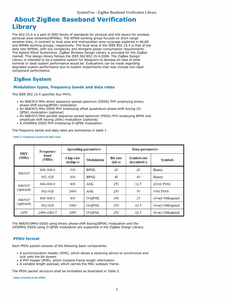
The IEEE 802.15.4 specifies four PHYs.
An 868/915 MHz direct sequence spread spectrum (DSSS) PHY employing binaryphase-shift keying(BPSK) modulationAn 868/915 MHz DSSS PHY employing offset quadrature phase-shift keying (O-QPSK) modulation (optional)An 868/915 MHz parallel sequence spread spectrum (PSSS) PHY employing BPSK andamplitude shift keying (ASK) modulation (optional)A 2450MHz DSSS PHY employing O-QPSK modulation.
The frequency bands and data rates are summaries in table 1
Table 1: Frequency bands and data rates
The 868/915MHz DSSS using binary phase-shift keying(BPSK) modulation and the2450MHz DSSS using O-QPSK modulation are supported in the ZigBee Design Library.
PPDU format
Each PPDU packet consists of the following basic components:
A synchronization header (SHR), which allows a receiving device to synchronize andlock onto the bit streamA PHY header (PHR), which contains frame length informationA variable length payload, which carries the MAC sublayer frame.
The PPDU packet structure shall be formatted as illustrated in Table 2.
Table 2:Format of the PPDU

SystemVue - ZigBee Baseband Verification Library
6
2450MHz PHY specifications
Modulation and spreading
The 2450 MHz PHY employs a 16-ary quasi-orthogonal modulation technique. During eachdata symbol period, four information bits are used to select one of 16 nearly orthogonalpseudo-random noise (PN) sequences to be transmitted. The PN sequences for successivedata symbols are concatenated, and the aggregate chip sequence is modulated onto thecarrier using offset quadrature phase-shift keying (O-QPSK). The reference modulationdiagram is illustrated in figure 1.
Figure 1: Modulation and spreading functions for OQPSK
The symbol-to-chip mapping is specified in Table 3.
Table 3: Symbol-to-chip mapping for O-QPSK

SystemVue - ZigBee Baseband Verification Library
7
The chip sequences representing each data symbol are modulated onto the carrier usingO-QPSK with halfsine pulse shaping. Even-indexed chips are modulated onto the in-phase(I) carrier and odd-indexed chips are modulated onto the quadrature-phase (Q) carrier.Because each data symbol is represented by a 32-chip sequence, the chip rate (nominally2.0 Mchip/s) is 32 times the symbol rate. To form the offset between I-phase and Q-phasechip modulation, the Q-phase chips shall be delayed by Tc with respect to the I-phasechips (see Figure 19), where Tc is the inverse of the chip rate. The O-QPSK chip offset isshown in figure 2.
Figure 2: O-QPSK chip offsets
The half-sine pulse shape used to represent each baseband chip is described by Equation
868/915MHz band binary phase-shift keying(BPSK) PHYspecifications
The 868/915 MHz BPSK PHY shall employ direct sequence spread spectrum (DSSS) withBPSK used for chip modulation and differential encoding used for data symbol encoding.The reference modulator diagram is shown in Figure 3.

SystemVue - ZigBee Baseband Verification Library
8
Figure 3: Modulation and spreading functions for BPSK
The Symbol-to-chip mapping is shown in Table 4.
Table 4: Symbol-to-chip mapping for BPSK
The raised cosine pulse shape (roll-off factor = 1) used to represent each baseband chip is
described by Equation
ZigBee LibraryEEsof SystemVue ZigBee library can support both 868/915MHz BPSK and 2450MHz O-QPSK modulation formats. It includes 6 components and 2 test benches.
Component Libraries
This ZigBee Wireless Design Library is organized by the types of behavioral models andsubnetworks.
Channel Model Components
UWB_Channel: UWB Channel model
Mapper Components
ZigBee_Despread: ZigBee despread and symbol demapper
Multiplex Components
ZigBee_DemuxFrame: ZigBee frame demultiplexer
Receiver Components
ZigBee_Receiver: ZigBee baseband receiver which both supports 868/915MHz BPSKand 2450MHz O-QPSK modulation.
Source Components
ZigBee_Source: ZigBee baseband signal source which both supports 868/915MHzBPSK and 2450MHz O-QPSK modulation.
Sync Equalization Components
ZigBee_FrameSync: ZigBee time and frequency synchronizer in time domain.
Reference
IEEE Std 802.15.4-2006 Wireless Medium Access Control (MAC) and Physical Layer1.(PHY) Specifications for Low-Rate Wireless Personal Area Networks (WPANs)

SystemVue - ZigBee Baseband Verification Library
9
UWB_Channel PartCategories: Channel Model (zigbeebasever)
The models associated with this part are listed below. To view detailed information on amodel (description, parameters, equations, notes, etc.), please click the appropriate link.
Model Description
UWB_Channel(zigbeebasever)
UWB Channel Model
UWB_Channel
Description: UWB Channel ModelDomain: UntimedC++ Code Generation Support: NOAssociated Parts: UWB Channel Part (zigbeebasever)
Model Parameters
Name Description Default Units Type RuntimeTunable
ChannelNumber Channel model type: CM_1, CM_2, CM_3,CM_4, CM_5, CM_6, CM_7, CM_8, CM_9
CM_1 Enumeration NO
ChannelSeedOption type of Random number seed to generatechannel impulse response: Random, Fixed
Random Enumeration NO
RandomNumberSeed Random number seed to create channel[0,2^31-1)
0 Integer NO
SampleRate sample rate of input signal [1KHz,16GHz] 8e9 Hz Float NO
CarrierFrequency carrier frequency [2GHz, 10GHz] 6e9 Hz Float NO
FilteringOption FFTBased needs more memory in non-MultiRate mode, SingleInSingleOut may beslower, FFTBasedSISO introduces extradelay: FFTBased, SingleInSingleOut,FFTBasedSISO
FFTBased Enumeration NO
InterpConfig interpolation filter parameter configuration:Default, UserDefined
Default Enumeration NO
InterpAlpha ratio of signal bandwidth to half sample ratewith which resampling filter will be optimized[0,1)
0.95 Float NO
InterpDelay delay of interpolation filter or half thenumber of samples used for interpolation[4,128]
24 Integer NO
Input Ports
Port Name Description Signal Type Optional
1 input Signals supplied to transmit array complex NO
Output Ports
Port Name Description Signal Type Optional
2 output Signals at output of receivearray
complex NO
Notes/Equations
This model simulates a generic channel model representing typical indoor and1.outdoor environments, in the frequency range of [2GHz, 10GHz], for evaluating802.15.4asystems. The radio channel around the human body is not included.It's implemented based on the m-code in [2].2.The output rms value is normalized to be the same as that of input signal. However,3.if the sample rate of input is small, the output rms may be much larger thanexpected because some multi-path clusters are gathered in one correlative timespan.The channel number CM_1~CM_9 correspond to different propagation environment in4.the following table

SystemVue - ZigBee Baseband Verification Library
10
channel number environment
CM_1 Residential LOS
CM_2 Residential NLOS
CM_3 Office LOS
CM_4 Office NLOS
CM_5 Outdoor LOS
CM_6 Outdoor NLOS
CM_7 Industrial LOS
CM_8 Industrial NLOS
CM_9 Open Outdoor NLOS
References
IEEE 802.15.4a channel model - final report r11. 15-05-0114-00-004a-ieee802-15-4a-channel-model-matlab-code-ver-92.

SystemVue - ZigBee Baseband Verification Library
11
ZigBee_Despread PartCategories: Mapper (zigbeebasever)
The models associated with this part are listed below. To view detailed information on amodel (description, parameters, equations, notes, etc.), please click the appropriate link.
Model Description
ZigBee_Despread(zigbeebasever)
ZigBee despread and symboldemapper
ZigBee_Despread
Description: ZigBee despread and symbol demapperDomain: UntimedC++ Code Generation Support: NOAssociated Parts: ZigBee Despread Part (zigbeebasever)
Model Parameters
Name Description Default Units Type RuntimeTunable
PHYFormat the type of PHY format:OQPSK_2000kchips/s,BPSK_600kchips/s,BPSK_300kchips/s
OQPSK_2000kchips/s Enumeration NO
PSDULength PSDU payload length in bytes 20 Integer NO
SamplesPerChip Samples per chip 4 Integer NO
Input Ports
Port Name Description Signal Type Optional
1 Input Input signal complex NO
Output Ports
Port Name Description Signal Type Optional
2 Output Output demapped bits int NO
Notes/Equations
This model despreads the input sequences and demaps to binary bits. For OQPSK1.modulation, the reverse process of bit-to-symbol mapping and symbol-to-chipmapping is performed. For BPSK modulation, the reverse process of differentialencoding and bit-to-chip mapping is performed.Each firing,2.DataSamples tokens are consumed at the input port, where DataSamples refers tothe number of samples of PHY payload in one burst and calculated as DataSamples(zigbeebasever).It equals to 5120 by default.PSDULength*8 tokens are produced at the output port.For OQPSK modulation, this model performs M-ary despread symbol by symbol.3.Firstly, the half sine pulse shaped PN sequences for data symbol#0,...symbol#15 aregenerated. Then the correlations of the input signal and all the PN sequences arecalculated. Lastly, the symbol index of the maximum correlation is output. Thesymbol to chip mapping is Symbol-to-chip mapping for OQPSK (zigbeebasever). Thehalf sine pulse shape is half sine pulse shape (zigbeebasever) .For BPSK modulation, the differential decoding is performed after despread. The4.input signal is correlated with the raised cosine pulse shapd PN sequence for bit 0symbol by symbol. Then the change of the phase between two symbols is detectedby multipying the correlation result with the complex-conjugation of the previouscorrelation result. The decision threshold is ±/2. The symbol to chip mapping isSymbol-to-chip mapping for BPSK (zigbeebasever). The raised cosine pulse shape israised cosine pulse shape (zigbeebasever) .
References
IEEE Std 802.15.4-2006 Wireless Medium Access Control (MAC) and Physical Layer1.(PHY) Specifications for Low-Rate Wireless Personal Area Networks (WPANs)
SystemVue - ZigBee Baseband Verification Library
12
ZigBee_DemuxFrame PartCategories: Multiplex (zigbeebasever)
The models associated with this part are listed below. To view detailed information on amodel (description, parameters, equations, notes, etc.), please click the appropriate link.
Model Description
ZigBee_DemuxFrame(zigbeebasever)
ZigBee framedemultiplexer
ZigBee_DemuxFrame
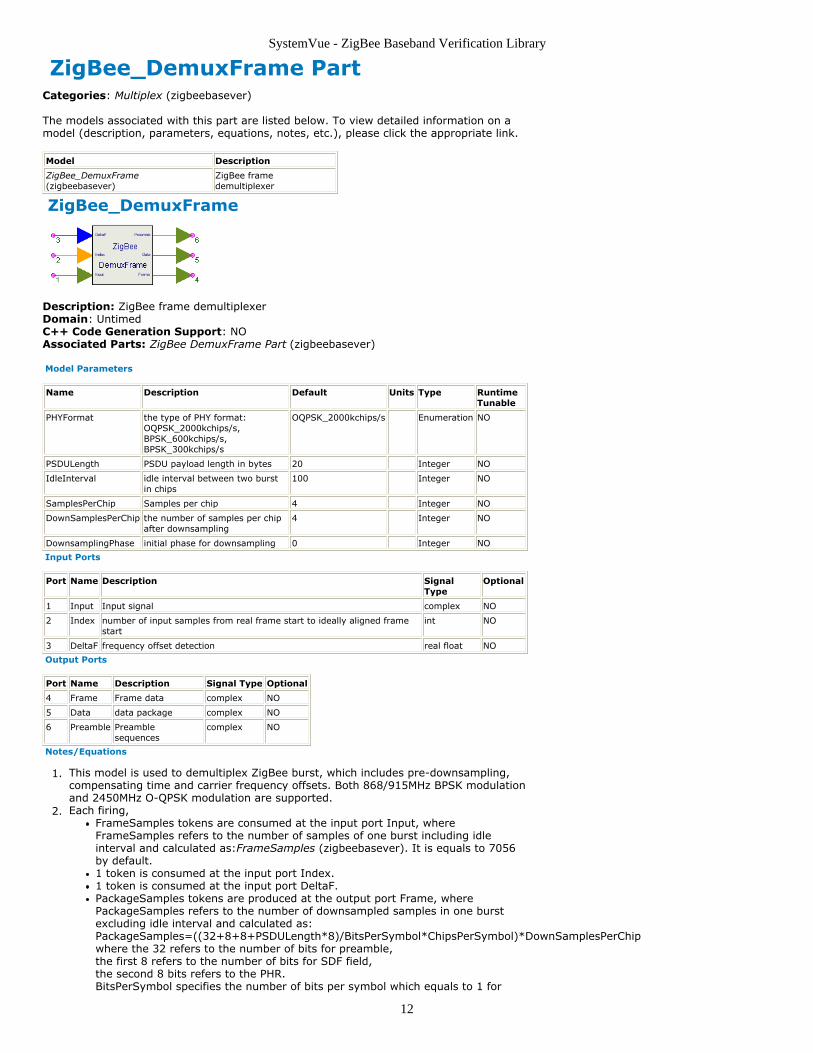
Description: ZigBee frame demultiplexerDomain: UntimedC++ Code Generation Support: NOAssociated Parts: ZigBee DemuxFrame Part (zigbeebasever)
Model Parameters
Name Description Default Units Type RuntimeTunable
PHYFormat the type of PHY format:OQPSK_2000kchips/s,BPSK_600kchips/s,BPSK_300kchips/s
OQPSK_2000kchips/s Enumeration NO
PSDULength PSDU payload length in bytes 20 Integer NO
IdleInterval idle interval between two burstin chips
100 Integer NO
SamplesPerChip Samples per chip 4 Integer NO
DownSamplesPerChip the number of samples per chipafter downsampling
4 Integer NO
DownsamplingPhase initial phase for downsampling 0 Integer NO
Input Ports
Port Name Description SignalType
Optional
1 Input Input signal complex NO
2 Index number of input samples from real frame start to ideally aligned framestart
int NO
3 DeltaF frequency offset detection real float NO
Output Ports
Port Name Description Signal Type Optional
4 Frame Frame data complex NO
5 Data data package complex NO
6 Preamble Preamblesequences
complex NO
Notes/Equations
This model is used to demultiplex ZigBee burst, which includes pre-downsampling,1.compensating time and carrier frequency offsets. Both 868/915MHz BPSK modulationand 2450MHz O-QPSK modulation are supported.Each firing,2.
FrameSamples tokens are consumed at the input port Input, whereFrameSamples refers to the number of samples of one burst including idleinterval and calculated as:FrameSamples (zigbeebasever). It is equals to 7056by default.1 token is consumed at the input port Index.1 token is consumed at the input port DeltaF.PackageSamples tokens are produced at the output port Frame, wherePackageSamples refers to the number of downsampled samples in one burstexcluding idle interval and calculated as:PackageSamples=((32+8+8+PSDULength*8)/BitsPerSymbol*ChipsPerSymbol)*DownSamplesPerChipwhere the 32 refers to the number of bits for preamble,the first 8 refers to the number of bits for SDF field,the second 8 bits refers to the PHR.BitsPerSymbol specifies the number of bits per symbol which equals to 1 for

SystemVue - ZigBee Baseband Verification Library
13
BPSK modulation and equals to 4 for O-QPSK modulation.ChipsPerSymbol specifies the number of chips per symbol which equals to 15 forBPSK modulation and equals to 32 for O-QPSK modulation.It equals to 6656 by default.DataSamples tokens are produced at the output port Data, where DataSamplesrefers to the number of downsampled samples of PHY payload in one burst andcalculated as: DataSamples=(PSDULength*8/BitsPerSymbol*ChipsPerSymbol*DownSamplesPerChip)It equals to 5120 by default.PreambleSamples tokens are produced at the output port Preamble, wherePreambleSamples refers to the number of downsampled samples of preamblefield in one burst and calculated as:PreambleSamples=32/BitsPerSymbol*ChipsPerSymbol*DownSamplesPerChipIt equals to 1024 by default.
Because of the transmission delay, a detected burst usually falls into 2 consecutive3.received blocks, so the buffer length for Input is 2*FrameSamples.The start point of the detected burst is determined by the token consumed at Index.4.Only after receiving the second input block, this model can output one actual burst.So this model causes one burst delay.The DeltaF inputs the estimated frequency offset ( ) of each received burst. The i-5.th estimated frequency offset ( ) compensates for the phase in the current burst
only. Assume( ) sequences are the input signals from Input, (
) are the sequences, whose phase caused by frequency offsetare removed, where N is the number of samples within burst.
Then where is frequency offset of the i-th received burst which is the input at DeltaF.Tstep=ChipRate*SamplesPerChip is the sample time interval in the system.ChipRate equals to 300kchips/s for 868MHz BPSK, 600kchips/s for 915MHz BPSK and2000kchips/s for 2450MHz O-QPSK.Since there are only in-phase parts for the BPSK modulation, delta omiga will beestimated and compensated to make sure the quadrature parts are zeros afterfrequency compensation.The parameter DownSamplesPerChip specifies the number of samples per chip for6.the output sequences. The parameter DownsamplingPhase specifies which onesample to output when downsampling. This parameter is ineffective whenDownSamplesPerChip equals to SamplerPerChip. For example, the SamplesPerChip =3, DownSamplesPerChip = 1 means the output is decimatd by three and only 1 ofevery three samples is selected. If DownsamplingPhase = 0, the first one of the threesamples will be selected, if DownSamplingPhase = 2, the last one of the threesamples will be selected.
The SamplesPerChip should be exactly devided by the DownSamplesPerChip in this model.A low-pass filter should be used as an anti-aliasing filter to reduce the bandwidth of the signalbefore the signal is downsampled.
References
IEEE Std 802.15.4-2006 Wireless Medium Access Control (MAC) and Physical Layer1.(PHY) Specifications for Low-Rate Wireless Personal Area Networks (WPANs)

SystemVue - ZigBee Baseband Verification Library
14
ZigBee_Receiver Part ZigBee baseband receiver
Categories: Receiver (zigbeebasever)
The models associated with this part are listed below. To view detailed information on amodel (description, parameters, equations, notes, etc.), please click the appropriate link.
Model
ZigBee_Receiver(zigbeebasever)
ZigBee_Receiver
Description: ZigBee baseband receiverAssociated Parts: ZigBee Receiver Part (zigbeebasever)
Model Parameters
Name Description Default Units Type RuntimeTunable
PHYFormat the type of PHY format:OQPSK_2000kchips/s,BPSK_600kchips/s, BPSK_300kchips/s
OQPSK_2000kchips/s Enumeration NO
PSDULength PSDU payload length in bytes 20 Integer NO
IdleInterval idle interval between two burst in chips 100 Integer NO
SamplesPerChip Samples per chip 4 Integer NO
CorrBlockNum Number of oversampled samples ineach sub correlation block
128 Integer NO
FreqSync Frequency estimation range selection:< 1/8 Symbol Rate, < 1/4 SymbolRate, < 1/2 Symbol Rate, < SymbolRate, < 2 Symbol Rate, < 4 SymbolRate, < 8 Symbol Rate
< 1/2 Symbol Rate Enumeration NO
SearchType start a new timing and frequencysynchronization search for every burstor not: Search every burst,Search+Track
Search every burst Enumeration NO
TrackingRange timing and frequency synchronizationtracking range for the bursts exceptthe first burst, valid when SearchTypeis Search_Track
0 Float NO
Input Ports
Port Name Description Signal Type Optional
1 Input Input of frame data in time domain complex NO
Output Ports
Port Name Description SignalType
Optional
2 PSDU Output of PHY payload int NO
3 Index number of input samples from real frame start to ideallyaligned frame start
int NO
4 DeltaF frequency offset detection real NO
5 DataSamples data package complex NO
6 PreambleSamples Preamble sequences complex NO
Parameters Details
For signal parameters details please refer to ZigBee source parameters (zigbeebasever)
Rx Algorithm Parameters Details:• CorrBlockNum: Number of oversampled samples in each sub correlation block. It is usedto calculate the correlation of the received signal and local preamble to get the startposition of the frame. CorrBlockNum should be choosen to meet the followingrequirements:

SystemVue - ZigBee Baseband Verification Library
15
1. It is larger than zero.2. It is no larger than the number of samples in one symbol.3. The number of samples in one symbol should be exactly devided by the CorrBlockNum.4. The frequency offset of the number of CorrBlockNum samples should be in the range(-π, π) which can be restrained by the receiver.• FreqSync:Frequency estimation range selection choosen from < 1/8 Symbol Rate, < 1/4Symbol Rate, < 1/2 Symbol Rate, < Symbol Rate, < 2 Symbol Rate, < 4 Symbol Rate. <8 Symbol Rate. The frequency estimator exhibits good accuracy while maintaining usefuloperating ranges.
The CorrBlockNum should not exceed the range of FreqSync. For example, if the FreqSync is set to'< 8 Symbol Rate' which means the frequency offset of (-π, π) is for 1/8 symbol time. TheCorrBlockNum should be no larger than the number of samples in 1/8 symbol to restrain thefrequency offset, otherwise the synchronization index may not be the right position.
• SearchType:the search type for the timing synchronization to identify whether to start anew timing and frequency synchronization search for every burst or not. WhenSearchType = Search every burst, the complete search is performed for each burst in thewhole burst; When SearchType = Search+Track, the first burst performs the completesearch in the whole burst, the rest bursts perform the tracking search whose search rangeis defined in TrackingRange.• TrackingRange: tracking range for the rest bursts when SearchType = Search+Track.This parameter is valid only when SearchType = Search+Track.
Notes/Equations
This subnetwork completes Std 802.15.4 ZigBee baseband receiver.1.The ZigBee_Receiver schematic is shown below:2.
Token number3.The port Input reads IQ data sequences for one burst. Each firing,FrameSamples tokens are produced at the port Input. Please refer toFrameSamples (zigbeebasever) for the calculation in detail.It is equal to 7056 by default.The port PSDU produces the PHY payload. The number of samples for the PSDUport per burst is calculated as:PSDULength*8. It is equal to 160 by default.The port Index produces the start position in sample of the burst. Each firing, 1token is produced.The port DeltaF produces the frequency offset of the burst. Each firing, 1 tokenis produced.The port DataSamples produces the IQ data samples with frequency offsetcompansation of the burst. Each firing,PSDULength*8/BitsPerSymbol*ChipsPerSymbol*DownSamplesPerChip tokensare procuded, whereBitsPerSymbol specifies the number of bits per symbol which equals to 1 forBPSK modulation and equals to 4 for O-QPSK modulation.ChipsPerSymbol specifies the number of chips per symbol which equals to 15 forBPSK modulation and equals to 32 for O-QPSK modulation.It is equal to 5120 by default.The port PreambleSamples produces the IQ data samples with frequency offsetcompansation of the burst.Each firing, (32+8+8)/BitsPerSymbol*ChipsPerSymbol*DownSamplesPerChiptokens are produced,where the 32 refers to the number of bits for preamble,the first 8 refers to the number of bits for SDF field,the second 8 bits refers to the PHR.BitsPerSymbol specifies the number of bits per symbol which equals to 1 forBPSK modulation and equals to 4 for O-QPSK modulation.

SystemVue - ZigBee Baseband Verification Library
16
ChipsPerSymbol specifies the number of chips per symbol which equals to 15 forBPSK modulation and equals to 32 for O-QPSK modulation.It is equal to 1536 by default.
First of all, the time and frequency synchronization are performed in4.ZigBee_FrameSync utilizing the preamble signal. Both timing synchronization indexand frequency offset from ZigBee_FrameSync are passed into theZigBee_DemuxFrame as well as the received signal.Then ZigBee_DemuxFrame compensated the frequency offset and outputs the real5.burst making use of the timing synchronization index. It should be noted that thismodel causes one burst delay.Lastly the ZigBee_Despread performs the reverse process of bit-to-symbol mapping6.and symbol-to-chip mapping by correlation with the local PN sequences. The binarydata is produced after the decision making.
The signal can be downsampled by the parameter DownSamplesPerChip in theZigBee_DemuxFrame and then despreaded with DownSamplesPerChip in ZigBee_Despread.This will introduce the SNR loss while speeding up simulation.
.
References
IEEE Std 802.15.4-2006 Wireless Medium Access Control (MAC) and Physical Layer1.(PHY) Specifications for Low-Rate Wireless Personal Area Networks (WPANs)

SystemVue - ZigBee Baseband Verification Library
17
ZigBee_Source Part ZigBee baseband signal source
Categories: Source (zigbeebasever)
The models associated with this part are listed below. To view detailed information on amodel (description, parameters, equations, notes, etc.), please click the appropriate link.
Model
ZigBee_Source(zigbeebasever)
ZigBee_Source
Description: ZigBee baseband signal sourceAssociated Parts: ZigBee Source Part (zigbeebasever)
Model Parameters
Name Description Default Units Type RuntimeTunable
PHYFormat the type of PHY format:OQPSK_2000kchips/s,BPSK_600kchips/s,BPSK_300kchips/s
OQPSK_2000kchips/s Enumeration NO
PSDULength PSDU payload length in bytes 20 Positiveinteger
NO
IdleInterval idle interval between two bursts inchips
100 Positiveinteger
NO
SamplesPerChip Samples per chip 4 Positiveinteger
NO
Input Ports
Port Name Description Signal Type Optional
1 PSDU Input of PHYpayload
int NO
Output Ports
Port Name Description Signal Type Optional
2 Frame output of frame data in timedomain
complex NO
Parameters Details:
• PHYFormat: specifies the type of PHY format. Three formats (OQPSK_2000kchips/s,BPSK_600kchips/s, BPSK_300kchips/s) are supported.• PSDULength: specifies the PSDU payload length in bytes.• IdleInterval: specifies the idle interval between two bursts in chips.• SamplesPerChip: specifies the samples per chip.
Notes/Equations
This subnetwork completes ZigBee baseband signal source. Both the 868/915MHz1.DSSS BPSK modulation and the 2450MHz DSSS O-QPSK modulation are supported.The ZigBee_Source schematic is shown below:

SystemVue - ZigBee Baseband Verification Library
18
Token number2.The port PSDU reads the the PSDU data. The number of samples for the PSDUport per burst is calculated as:PSDULength*8. It is equal to 160 by default. The port Frame produces IQ data sequences for one burst. Each firing,FrameSamples tokens are produced at the port Frame.FrameSamples=((32+8+8+PSDULength*8)/BitsPerSymbol*ChipsPerSymbol+IdleIntrval)*SamplesPerChip,where the 32 refers to the number of bits for preamble,the first 8 refers to the number of bits for SDF field,the second 8 bits refers to the PHR.BitsPerSymbol specifies the number of bits per symbol which equals to 1 forBPSK modulation and equals to 4 for O-QPSK modulation.ChipsPerSymbol specifies the number of chips per symbol which equals to 15 forBPSK modulation and equals to 32 for O-QPSK modulation.It is equal to 7056 by default.
The input of this subnetwork is PSDU data. The schematic is split into two seperate3.parts, the half one on the top completes the DSSS BPSK modulation as: PPDUmultiplexer, differential encoder, bit-to-chip mapping, BPSK modulation with raisedcosine pulse shape. The half one on the bottom completes the DSSS O-QPSKmodulation as: PPDU multiplexer, bit-to-chip mapping, O-QPSK modulation with halfsine pulse shape. If the PHYFormat is selected to OQPSK_2000kbhips/s, the half oneon the top will be inactive. Otherwise, the half one on the bottom will be inactive. Theformat of PPDU is PPDU format (zigbeebasever).For all PHYs except for the ASK PHY, the Preamble field shall be binary zeros. The4.preamble field length is shown in Table 1.
Table 1: Preamble field length
For all PHYs except for the ASK PHY, the SDF is an 8-bit field. The SFD field length is5.shown in Table 2. The format of the SFD field is shown in Table 3.

SystemVue - ZigBee Baseband Verification Library
19
Table 2: SDF field length
Table 3: Format of the SFD field(except for ASK)
The modulation and spreading for 2450MHz O-QPSK is 2450MHz PHY specifications(zigbeebasever).The modulation and spreading for 868/915MHz BPSK is 868/915MHz BPSK PHYspecifications (zigbeebasever).
References
IEEE Std 802.15.4-2006 Wireless Medium Access Control (MAC) and Physical Layer1.(PHY) Specifications for Low-Rate Wireless Personal Area Networks (WPANs)

SystemVue - ZigBee Baseband Verification Library
20
ZigBee_FrameSync PartCategories: Sync Equalization (zigbeebasever)
The models associated with this part are listed below. To view detailed information on amodel (description, parameters, equations, notes, etc.), please click the appropriate link.
Model Description
ZigBee_FrameSync(zigbeebasever)
ZigBee time and frequency synchronizer in timedomain
ZigBee_FrameSync
Description: ZigBee time and frequency synchronizer in time domainDomain: UntimedC++ Code Generation Support: NOAssociated Parts: ZigBee FrameSync Part (zigbeebasever)
Model Parameters
Name Description Default Units Type RuntimeTunable
PHYFormat the type of PHY format:OQPSK_2000kchips/s,BPSK_600kchips/s, BPSK_300kchips/s
OQPSK_2000kchips/s Enumeration NO
PSDULength PSDU payload length in bytes 20 Integer NO
IdleInterval idle interval between two burst in chips 100 Integer NO
SamplesPerChip Samples per chip 4 Integer NO
CorrBlockNum Number of oversampled samples ineach sub correlation block
32 Integer NO
FreqSync Frequency estimation range selection:< 1/8 Symbol Rate, < 1/4 SymbolRate, < 1/2 Symbol Rate, < SymbolRate, < 2 Symbol Rate, < 4 SymbolRate, < 8_Symbol Rate
< 1/2 Symbol Rate Enumeration NO
SearchType start a new timing and frequencysynchronization search for every burstor not: Search every burst,Search+Track
Search every burst Enumeration NO
TrackingRange timing and frequency synchronizationtracking range for the bursts exceptthe first burst, valid when SearchTypeis Search_Track
20e-6 Float NO
Input Ports
Port Name Description Signal Type Optional
1 Input Input signal complex NO
Output Ports
Port Name Description SignalType
Optional
2 Index number of input samples from real frame start to ideally aligned framestart
int NO
3 DeltaF frequency offset detection real float NO
4 Corr correlation result real float NO
Notes/Equations
This model is used to achieve burst synchronization and frequency offset estimation1.for ZigBee system. Both 868/915MHz BPSK modulation and 2450MHz O-QPSKmodulation are supported.Each firing,2.
FrameSamples tokens are consumed at the input port, where FrameSamplesrefers to the number of samples of one burst including idle interval andcalculated as:FrameSamples (zigbeebasever). It is equal to 7056 by default.1 token is produced at the output port Index.1 token is produced at the output port DeltaF.FrameSamples tokens are produced at the output port Corr, whereFrameSamples refers to the number of samples of one burst including idleinterval and calculated as:FrameSamples (zigbeebasever). It is equal to 7056 by

SystemVue - ZigBee Baseband Verification Library
21
default.The Preamble field is used by this model to obtain the start position of the burst by3.the correlation of the receiverd signal and the local preamble field. The correlation iscalculated as block correlations to suppress the carrier frequency deviation. Firstly,the preamble field and the input signal is devided into subblocks and the number ofsamples in the subblock is specified by the parameter CorrBlockNum. As showsbelow:
In each subblock, the input signal is correlated with the local preamble field as
Then the correlation is calcuated as:
When i is the start position of the burst, the correlation get maximum.The frequency offset of the CorrBlockNum should be in the range (-π, π).When the parameter SearchType is set to "Search every burst", the search is done4.burst by burst in the whole burst period.When the parameter SearchType is set to "Search+Track", the timingsynchronization is divided into two steps: Initial searching and Tracking searching.The initial searching is performed on the first burst, the same as when SearchType =Search every burst. Then beginning with the second burst, tracking searching isemployed. Tracking searching will search the range [Index- TrackRange/2,Index+TrackRange/2] to get the timing synchronization index, where Index is thetiming synchronization index gotten in the previous burst.When the FreqSync is set to "<1/8 Symbol Rate", "<1/4 Symbol Rate" and "<1/25.Symbol Rate", the auto-correlation of the input signal is calculated to get thefrequency offset as
.where the Index refers to the start position of the burst gotten from the above.PreambleSamples refers to the number of samples of preamble field in one burst.The CorrLength should be chosen to get the appropriate accuracy of the frequencyoffset.The frequency offset is calculated as:
where SamplingRate = SamplesPerChip*ChipRateChipRate is equal to 2000kchips/s for 2450MHz O-QPSK modulation, equal to600kchips/s for 915MHz BPSK modulation and equal to 300kchips/s for 868MHz BPSKmodulation.When the FreqSync is set to "<Symbol Rate", "<2 Symbol Rate" , "<4 Symbol Rate"and "<8 Symbol Rate", the correlation between the input signal and local PNsequences is calculated to get the frequency offset.
The CorrBlockNum should not exceed the range of FreqSync. For example, if the FreqSync isset to '< 8 Symbol Rate' which means the frequency offset of (-π, π) is for 1/8 symbol time.The CorrBlockNum should be no larger than the number of samples in 1/8 symbol to restrainthe frequency offset, otherwise the synchronization index may not be the actual position.
References
IEEE Std 802.15.4-2006 Wireless Medium Access Control (MAC) and Physical Layer1.(PHY) Specifications for Low-Rate Wireless Personal Area Networks (WPANs)