mimochannel baseband verification libraryedadownload.software.keysight.com/.../mimocbasever.pdf ·...
TRANSCRIPT


SystemVue - MIMOChannel Baseband Verification Library
1
SystemVue 2010.072010
MIMOChannel Baseband Verification Library
SystemVue - MIMOChannel Baseband Verification Library
2
© Agilent Technologies, Inc. 2000-2010395 Page Mill Road, Palo Alto, CA 94304 U.S.A.No part of this manual may be reproduced in any form or by any means (includingelectronic storage and retrieval or translation into a foreign language) without prioragreement and written consent from Agilent Technologies, Inc. as governed by UnitedStates and international copyright laws.
Acknowledgments Mentor Graphics is a trademark of Mentor Graphics Corporation inthe U.S. and other countries. Microsoft®, Windows®, MS Windows®, Windows NT®, andMS-DOS® are U.S. registered trademarks of Microsoft Corporation. Pentium® is a U.S.registered trademark of Intel Corporation. PostScript® and Acrobat® are trademarks ofAdobe Systems Incorporated. UNIX® is a registered trademark of the Open Group. Java™is a U.S. trademark of Sun Microsystems, Inc. SystemC® is a registered trademark ofOpen SystemC Initiative, Inc. in the United States and other countries and is used withpermission. MATLAB® is a U.S. registered trademark of The Math Works, Inc.. HiSIM2source code, and all copyrights, trade secrets or other intellectual property rights in and tothe source code in its entirety, is owned by Hiroshima University and STARC.
Errata The SystemVue product may contain references to "HP" or "HPEESOF" such as infile names and directory names. The business entity formerly known as "HP EEsof" is nowpart of Agilent Technologies and is known as "Agilent EEsof". To avoid broken functionalityand to maintain backward compatibility for our customers, we did not change all thenames and labels that contain "HP" or "HPEESOF" references.
Warranty The material contained in this document is provided "as is", and is subject tobeing changed, without notice, in future editions. Further, to the maximum extentpermitted by applicable law, Agilent disclaims all warranties, either express or implied,with regard to this manual and any information contained herein, including but not limitedto the implied warranties of merchantability and fitness for a particular purpose. Agilentshall not be liable for errors or for incidental or consequential damages in connection withthe furnishing, use, or performance of this document or of any information containedherein. Should Agilent and the user have a separate written agreement with warrantyterms covering the material in this document that conflict with these terms, the warrantyterms in the separate agreement shall control.
Technology Licenses The hardware and/or software described in this document arefurnished under a license and may be used or copied only in accordance with the terms ofsuch license.
Portions of this product is derivative work based on the University of California PtolemySoftware System.
In no event shall the University of California be liable to any party for direct, indirect,special, incidental, or consequential damages arising out of the use of this software and itsdocumentation, even if the University of California has been advised of the possibility ofsuch damage.
The University of California specifically disclaims any warranties, including, but not limitedto, the implied warranties of merchantability and fitness for a particular purpose. Thesoftware provided hereunder is on an "as is" basis and the University of California has noobligation to provide maintenance, support, updates, enhancements, or modifications.
Portions of this product include code developed at the University of Maryland, for theseportions the following notice applies.
In no event shall the University of Maryland be liable to any party for direct, indirect,special, incidental, or consequential damages arising out of the use of this software and itsdocumentation, even if the University of Maryland has been advised of the possibility ofsuch damage.
The University of Maryland specifically disclaims any warranties, including, but not limitedto, the implied warranties of merchantability and fitness for a particular purpose. thesoftware provided hereunder is on an "as is" basis, and the University of Maryland has noobligation to provide maintenance, support, updates, enhancements, or modifications.
Portions of this product include the SystemC software licensed under Open Source terms,
SystemVue - MIMOChannel Baseband Verification Library
3
which are available for download at http://systemc.org/ . This software is redistributed byAgilent. The Contributors of the SystemC software provide this software "as is" and offerno warranty of any kind, express or implied, including without limitation warranties orconditions or title and non-infringement, and implied warranties or conditionsmerchantability and fitness for a particular purpose. Contributors shall not be liable forany damages of any kind including without limitation direct, indirect, special, incidentaland consequential damages, such as lost profits. Any provisions that differ from thisdisclaimer are offered by Agilent only.With respect to the portion of the Licensed Materials that describes the software andprovides instructions concerning its operation and related matters, "use" includes the rightto download and print such materials solely for the purpose described above.
Restricted Rights Legend If software is for use in the performance of a U.S.Government prime contract or subcontract, Software is delivered and licensed as"Commercial computer software" as defined in DFAR 252.227-7014 (June 1995), or as a"commercial item" as defined in FAR 2.101(a) or as "Restricted computer software" asdefined in FAR 52.227-19 (June 1987) or any equivalent agency regulation or contractclause. Use, duplication or disclosure of Software is subject to Agilent Technologies´standard commercial license terms, and non-DOD Departments and Agencies of the U.S.Government will receive no greater than Restricted Rights as defined in FAR 52.227-19(c)(1-2) (June 1987). U.S. Government users will receive no greater than LimitedRights as defined in FAR 52.227-14 (June 1987) or DFAR 252.227-7015 (b)(2) (November1995), as applicable in any technical data.

SystemVue - MIMOChannel Baseband Verification Library
4
About MIMO Channel Builder . . . . . . . . . . . . . . . . . . . . . . . . . . . . . . . . . . . . . . . . . . . . . . . . 5 Channel_Capacity Part . . . . . . . . . . . . . . . . . . . . . . . . . . . . . . . . . . . . . . . . . . . . . . . . . . . . 7
Channel_Capacity . . . . . . . . . . . . . . . . . . . . . . . . . . . . . . . . . . . . . . . . . . . . . . . . . . . . . . 7 Correlation_Channel Part . . . . . . . . . . . . . . . . . . . . . . . . . . . . . . . . . . . . . . . . . . . . . . . . . . . 9
Correlation_Channel . . . . . . . . . . . . . . . . . . . . . . . . . . . . . . . . . . . . . . . . . . . . . . . . . . . . 9 WINNERII_Channel Part . . . . . . . . . . . . . . . . . . . . . . . . . . . . . . . . . . . . . . . . . . . . . . . . . . . 16
WINNERII_Channel . . . . . . . . . . . . . . . . . . . . . . . . . . . . . . . . . . . . . . . . . . . . . . . . . . . . . 16
SystemVue - MIMOChannel Baseband Verification Library
5
About MIMO Channel BuilderThe Agilent EEsof MIMO Channel Builder is for channel modeling market. It consists ofgeometry based Winner II MIMO channel model and correlation based MIMO channelmodel. Both MIMO channel models can support realistic antenna patterns. It can provideMIMO channel models for LTE and 4G system. It is based on Agilent SystemVue.The MIMO Channel Builder package includes basic components, application examples.After installation, the MIMO Channel Builder is available in the ChannelEmulator librarygroup and palette.The MIMO Channel Builder Examples are available in \SystemVue\Examples\BasebandVerification\ChannelModel.
Key features1.Winner II MIMO channel modela) Characteristics of WINNER II channel model:b) Geometry based stochastic modelc) Generate channel coefficients based on ray-based sumd) Abundant environment parameters selectione) Support simulation of multiple drop, segmentf) Support link level and system level simulationg) Ability to simulate arbitrary antenna pattern influenceh) Support CDL & non-CDL simulation modei) For non-CDL mode, channel parameters are determined based on statisticaldistributionsCorrelation based MIMO channel modela) Extend SISO models to MIMO by applying correlation to each tapb) Generate channel coefficients by filtering noise and applying correlationc) Support all kinds of user-defined parameters: PDP, AoA, AOD, PAS, K-factor,etc.d) Support arbitrary antenna pattern
COMPONENT LISTS2.channel_CapacityCorrelation_ChannelWINNERII_Channel
TEST BENCHES3.The MIMO Channel Builder provides three workspaces.
ChannelCapacity_Measurements.wsvThis workspace demonstrates the channel capacity for WinnerII channel and thecorrelation based channel. It shows the channel capacity change by usingdifferent antenna pattern. The channels are configured to be 2X2 MIMO mode.The calculation of channel capacity is focused on one path for the multi-pathchannel.ChannelImR_Measurements.wsvThis workspace demonstrates the impulse response, power spectrum and thefading waveform for WinnerII channel or the correlation based channel. Thechannels are configured to be 2X2 MIMO mode.ChannelThoughtput_LTE.wsvThis workspace demonstrates swept Thoughput vs SNR measurements for LTEdownlink in WinnerII and correlation based MIMO channel models.
References
D1.1.2V1.1, “WINNER II channel models”1.Laurent Schumacher, and Balaji Raghothaman, “closed form expressions for the2.correlation coefficient of directive antennas impinged by a multimodal truncatedlaplacian PAS,” IEEE TRANSACTIONS ON WIRELESS COMMUNICATIONS, VOL. 4, NO.4, page 1351-1359, JULY 2005.RODNEY G. VAUGHAN, “Polarization diversity in mobile communications”, IEEE3.TRANSACTIONS ON VEHICULAR TECHNOLOGY, VOL. 39, NO. 3, page 177-186,AUGUST 1990.Rohit U. Nabar, Helmut Bölcskei,Vinko Erceg, David Gesbert, and Arogyaswami J.4.Paulraj, “Performance of multiantenna signaling techniques in the presence ofpolarization diversity,” IEEE TRANSACTIONS ON SIGNAL PROCESSING, VOL. 50, NO.10, page 2553-2562, OCTOBER 2002.Jean Philippe Kermoal, Laurent Schumacher,Klaus Ingemann Pedersen, Preben5.Elgaard Mogensen, and Frank Frederiksen, “A stochastic MIMO radio channel modelwith experimental validation”, IEEE JOURNAL ON SELECTED AREAS IN
SystemVue - MIMOChannel Baseband Verification Library
6
COMMUNICATIONS, VOL. 20, NO. 6, page 1221-1226, AUGUST 2002.3GPP TSG-RAN R4-091361, Agilent Technologies, MIMO OTA methodology proposal,6.3GPP-TSG-RAN WG4 #bis 50, Seoul, Korea, 23rd – 27th March 2009.3GPP TSG-RAN R4-091949, Agilent Technologies, Applying measured MIMO antenna7.patterns to MIMO channel models for OTA analysis, 3GPP-TSG-RAN WG4 #51, SanFrancisco, USA, 4th – 8th May 2009.

SystemVue - MIMOChannel Baseband Verification Library
7
Channel_Capacity PartCategories: MIMOChannel Category (mimocbasever)
The models associated with this part are listed below. To view detailed information on amodel (description, parameters, equations, notes, etc.), please click the appropriate link.
Model Description
Channel_Capacity(mimocbasever)
Calculate the channel capacity based on the channel correlation matrix andchannel coefficients
Channel_Capacity
Description: Calculate the channel capacity based on the channel correlation matrix andchannel coefficientsDomain: UntimedC++ Code Generation Support: NOAssociated Parts: Channel Capacity Part (mimocbasever)
Model Parameters
Name Description Default Units Type RuntimeTunable
NumberofTx Number of transmitter antenna, range [1, 8] 2 Integer NO
NumberofRx Number of receiver antenna, range [1, 8] 2 Integer NO
NumSamples Number of samples to measure, range [1, inf] 1 Integer NO
SNR Signal to noise power ratio in dB, range [-100,30]
10 Float NO
CorrMatrix_I_FileName The filename of Correlation matrix real part Filename NO
CorrMatrix_Q_FileName The filename of Correlation matrix imag part Filename NO
Seed Seed of random integer number generator,range [0, 2^32-1]. When set to 0, thesimulation data is generated randomly for eachsimulation run. For each non-zoro setting, thesimulation can be repeated
0 Integer NO
Output Ports
Port Name Signal Type Optional
1 Capacity real NO
Notes/Equations
This model is used to calculate the channel capacity for the MIMO channel based on1.the channel correlation matrix and channel coefficients.This model reads 2 files which give the number of samples of the drops and the real2.part and the imaginary part of the corresponding channel correlation matrix R (theKronecker product of the transmit and receive correlation matrices), the matrix sizeis KxK, where K is NumberofTx*NumberofRx. And the channel correlation matrix Rcombine all the paths together. The channel coefficients are generated in this model.And the coefficients length is determined by the parameter NumSamples.
If the number of samples of drop 1 (the first integer in the read file) is less thanNumSamples, the number of samples and channel correlation matrix of nextdrop will be used. While if there is no data of next drop in these files, the data ofdrop 1 will be used repeatedly.
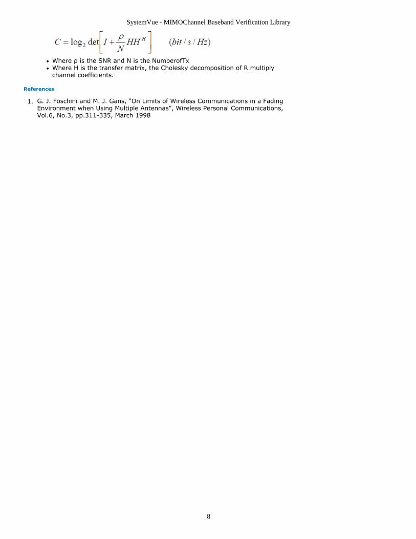
The parameter NumberofTx and NumberofRx represent the number of Tx antennas3.and Rx antennas. The NumSamples represents the length of channel coefficients. TheSNR represents the signal to noise power ratio in dB.The channel capacity calculation is shown as below,4.
SystemVue - MIMOChannel Baseband Verification Library
8
Where ρ is the SNR and N is the NumberofTxWhere H is the transfer matrix, the Cholesky decomposition of R multiplychannel coefficients.
References
G. J. Foschini and M. J. Gans, “On Limits of Wireless Communications in a Fading1.Environment when Using Multiple Antennas”, Wireless Personal Communications,Vol.6, No.3, pp.311-335, March 1998
SystemVue - MIMOChannel Baseband Verification Library
9
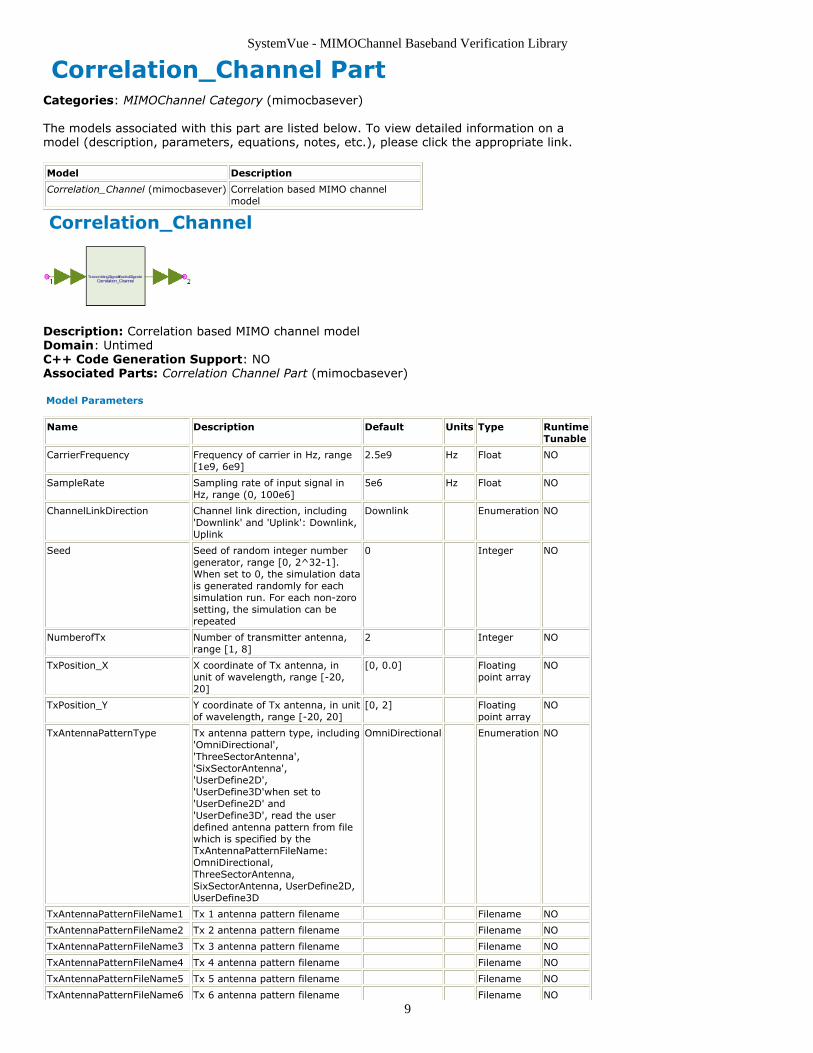
Correlation_Channel PartCategories: MIMOChannel Category (mimocbasever)
The models associated with this part are listed below. To view detailed information on amodel (description, parameters, equations, notes, etc.), please click the appropriate link.
Model Description
Correlation_Channel (mimocbasever) Correlation based MIMO channelmodel
Correlation_Channel
Description: Correlation based MIMO channel modelDomain: UntimedC++ Code Generation Support: NOAssociated Parts: Correlation Channel Part (mimocbasever)
Model Parameters
Name Description Default Units Type RuntimeTunable
CarrierFrequency Frequency of carrier in Hz, range[1e9, 6e9]
2.5e9 Hz Float NO
SampleRate Sampling rate of input signal inHz, range (0, 100e6]
5e6 Hz Float NO
ChannelLinkDirection Channel link direction, including'Downlink' and 'Uplink': Downlink,Uplink
Downlink Enumeration NO
Seed Seed of random integer numbergenerator, range [0, 2^32-1].When set to 0, the simulation datais generated randomly for eachsimulation run. For each non-zorosetting, the simulation can berepeated
0 Integer NO
NumberofTx Number of transmitter antenna,range [1, 8]
2 Integer NO
TxPosition_X X coordinate of Tx antenna, inunit of wavelength, range [-20,20]
[0, 0.0] Floatingpoint array
NO
TxPosition_Y Y coordinate of Tx antenna, in unitof wavelength, range [-20, 20]
[0, 2] Floatingpoint array
NO
TxAntennaPatternType Tx antenna pattern type, including'OmniDirectional','ThreeSectorAntenna','SixSectorAntenna','UserDefine2D','UserDefine3D'when set to'UserDefine2D' and'UserDefine3D', read the userdefined antenna pattern from filewhich is specified by theTxAntennaPatternFileName:OmniDirectional,ThreeSectorAntenna,SixSectorAntenna, UserDefine2D,UserDefine3D
OmniDirectional Enumeration NO
TxAntennaPatternFileName1 Tx 1 antenna pattern filename Filename NO
TxAntennaPatternFileName2 Tx 2 antenna pattern filename Filename NO
TxAntennaPatternFileName3 Tx 3 antenna pattern filename Filename NO
TxAntennaPatternFileName4 Tx 4 antenna pattern filename Filename NO
TxAntennaPatternFileName5 Tx 5 antenna pattern filename Filename NO
TxAntennaPatternFileName6 Tx 6 antenna pattern filename Filename NO

SystemVue - MIMOChannel Baseband Verification Library
10
TxAntennaPatternFileName7 Tx 7 antenna pattern filename Filename NO
TxAntennaPatternFileName8 Tx 8 antenna pattern filename Filename NO
TxPhaseCenter Wheter all the Tx elements sharethe same phase center: NO, YES
NO Enumeration NO
TxRotationAngle Tx roation angle in the horizontal,in unit of degree, range [-180,180]
0 Float NO
TxElevationAngle Tx elevation angle, in unit ofdegree, range [0, 180]
90 Float NO
NumberofRx Number of receiver antenna,range [1, 8]
2 Integer NO
RxPosition_X X coordinate of Rx antenna, inunit of wavelength, range [-20,20]
[0, 0.0] Floatingpoint array
NO
RxPosition_Y Y coordinate of Rx antenna, inunit of wavelength, range [-20,20]
[0, 0.5] Floatingpoint array
NO
RxAntennaPatternType Rx antenna pattern type, including'OmniDirectional','ThreeSectorAntenna','SixSectorAntenna','UserDefine2D','UserDefine3D'when set to'UserDefine2D','UserDefine3D'readthe user defined antenna patternfrom file which is specified by theRxAntennaPatternFileName:OmniDirectional,ThreeSectorAntenna,SixSectorAntenna, UserDefine2D,UserDefine3D
OmniDirectional Enumeration NO
RxAntennaPatternFileName1 Rx 1 antenna pattern filename Filename NO
RxAntennaPatternFileName2 Rx 2 antenna pattern filename Filename NO
RxAntennaPatternFileName3 Rx 3 antenna pattern filename Filename NO
RxAntennaPatternFileName4 Rx 4 antenna pattern filename Filename NO
RxAntennaPatternFileName5 Rx 5 antenna pattern filename Filename NO
RxAntennaPatternFileName6 Rx 6 antenna pattern filename Filename NO
RxAntennaPatternFileName7 Rx 7 antenna pattern filename Filename NO
RxAntennaPatternFileName8 Rx 8 antenna pattern filename Filename NO
RxPhaseCenter Wheter all the Rx elements sharethe same phase center: NO, YES
NO Enumeration NO
RxRotationAngle Rx roation angle in the horizontal,in unit of degree, range [-180,180]
0 Float NO
RxElevationAngle Rx elevation angle, in unit ofdegree, range [0, 180]
90 Float NO
ThetaBs Angle between the BS-MS LOSand the BS broadside, in unit ofdegree, range [-180, 180]
0 Float NO
ThetaMs Angle between the BS-MS LOSand the MS broadside, in unit ofdegree, range [-180, 180]
0 Float NO
MSVelocity Mobile station velocity (km/h),range [0, 500]
50 Float NO
MSDirection Mobile station moving direction(degree), [-180, 180]
30 Float NO
PASType Flag to indicate the PAS shape,including Laplacian, Gaussian andUniform: Laplacian, Gaussian,Uniform
Laplacian Enumeration NO
RayleighSpectrumShape Flag to indicate the Rayleighspectrum shape, includingClassical6db, Classical3db, Flat,Rounded and BellShape:Classical6db, Classical3db, Flat,Rounded, BellShape
Classical6db Enumeration NO
XPRindB Power ratio betwwen vertical-tohorizontal and vertical-to-vertical polarisations in dB, thevalue should be in range (-inf, 0]
-8 Float NO
SystemVue - MIMOChannel Baseband Verification Library
11
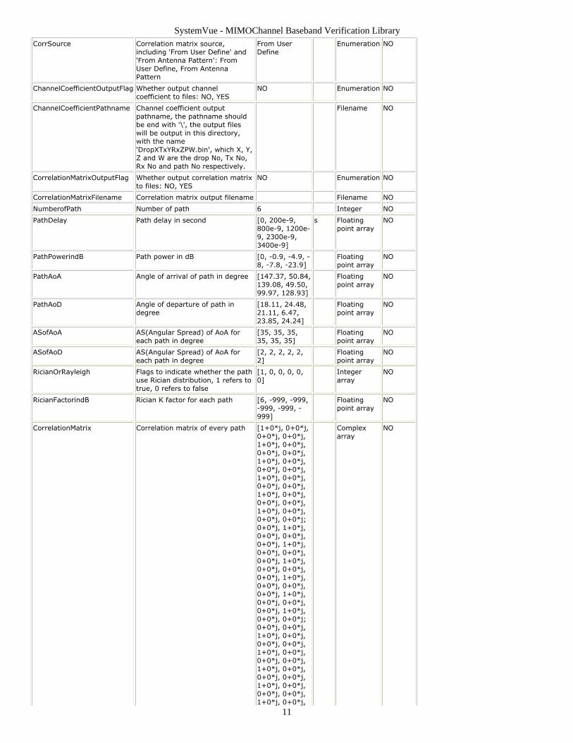
CorrSource Correlation matrix source,including 'From User Define' and'From Antenna Pattern': FromUser Define, From AntennaPattern
From UserDefine
Enumeration NO
ChannelCoefficientOutputFlag Whether output channelcoefficient to files: NO, YES
NO Enumeration NO
ChannelCoefficientPathname Channel coefficient outputpathname, the pathname shouldbe end with '\', the output fileswill be output in this directory,with the name'DropXTxYRxZPW.bin', which X, Y,Z and W are the drop No, Tx No,Rx No and path No respectively.
Filename NO
CorrelationMatrixOutputFlag Whether output correlation matrixto files: NO, YES
NO Enumeration NO
CorrelationMatrixFilename Correlation matrix output filename Filename NO
NumberofPath Number of path 6 Integer NO
PathDelay Path delay in second [0, 200e-9,800e-9, 1200e-9, 2300e-9,3400e-9]
s Floatingpoint array
NO
PathPowerindB Path power in dB [0, -0.9, -4.9, -8, -7.8, -23.9]
Floatingpoint array
NO
PathAoA Angle of arrival of path in degree [147.37, 50.84,139.08, 49.50,99.97, 128.93]
Floatingpoint array
NO
PathAoD Angle of departure of path indegree
[18.11, 24.48,21.11, 6.47,23.85, 24.24]
Floatingpoint array
NO
ASofAoA AS(Angular Spread) of AoA foreach path in degree
[35, 35, 35,35, 35, 35]
Floatingpoint array
NO
ASofAoD AS(Angular Spread) of AoA foreach path in degree
[2, 2, 2, 2, 2,2]
Floatingpoint array
NO
RicianOrRayleigh Flags to indicate whether the pathuse Rician distribution, 1 refers totrue, 0 refers to false
[1, 0, 0, 0, 0,0]
Integerarray
NO
RicianFactorindB Rician K factor for each path [6, -999, -999,-999, -999, -999]
Floatingpoint array
NO
CorrelationMatrix Correlation matrix of every path [1+0*j, 0+0*j,0+0*j, 0+0*j,1+0*j, 0+0*j,0+0*j, 0+0*j,1+0*j, 0+0*j,0+0*j, 0+0*j,1+0*j, 0+0*j,0+0*j, 0+0*j,1+0*j, 0+0*j,0+0*j, 0+0*j,1+0*j, 0+0*j,0+0*j, 0+0*j;0+0*j, 1+0*j,0+0*j, 0+0*j,0+0*j, 1+0*j,0+0*j, 0+0*j,0+0*j, 1+0*j,0+0*j, 0+0*j,0+0*j, 1+0*j,0+0*j, 0+0*j,0+0*j, 1+0*j,0+0*j, 0+0*j,0+0*j, 1+0*j,0+0*j, 0+0*j;0+0*j, 0+0*j,1+0*j, 0+0*j,0+0*j, 0+0*j,1+0*j, 0+0*j,0+0*j, 0+0*j,1+0*j, 0+0*j,0+0*j, 0+0*j,1+0*j, 0+0*j,0+0*j, 0+0*j,1+0*j, 0+0*j,
Complexarray
NO
SystemVue - MIMOChannel Baseband Verification Library
12
0+0*j, 0+0*j,1+0*j, 0+0*j;0+0*j, 0+0*j,0+0*j, 1+0*j,0+0*j, 0+0*j,0+0*j, 1+0*j,0+0*j, 0+0*j,0+0*j, 1+0*j,0+0*j, 0+0*j,0+0*j, 1+0*j,0+0*j, 0+0*j,0+0*j, 1+0*j,0+0*j, 0+0*j,0+0*j, 1+0*j]
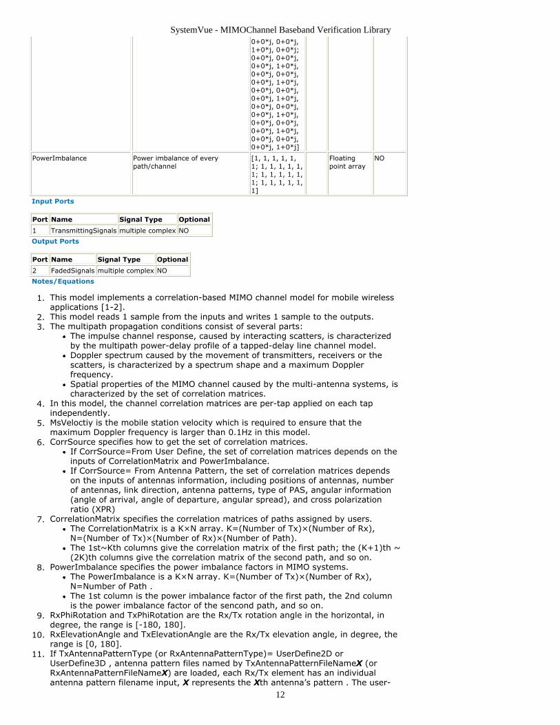
PowerImbalance Power imbalance of everypath/channel
[1, 1, 1, 1, 1,1; 1, 1, 1, 1, 1,1; 1, 1, 1, 1, 1,1; 1, 1, 1, 1, 1,1]
Floatingpoint array
NO
Input Ports
Port Name Signal Type Optional
1 TransmittingSignals multiple complex NO
Output Ports
Port Name Signal Type Optional
2 FadedSignals multiple complex NO
Notes/Equations
This model implements a correlation-based MIMO channel model for mobile wireless1.applications [1-2].This model reads 1 sample from the inputs and writes 1 sample to the outputs.2.The multipath propagation conditions consist of several parts:3.
The impulse channel response, caused by interacting scatters, is characterizedby the multipath power-delay profile of a tapped-delay line channel model.Doppler spectrum caused by the movement of transmitters, receivers or thescatters, is characterized by a spectrum shape and a maximum Dopplerfrequency.Spatial properties of the MIMO channel caused by the multi-antenna systems, ischaracterized by the set of correlation matrices.
In this model, the channel correlation matrices are per-tap applied on each tap4.independently.MsVeloctiy is the mobile station velocity which is required to ensure that the5.maximum Doppler frequency is larger than 0.1Hz in this model.CorrSource specifies how to get the set of correlation matrices.6.
If CorrSource=From User Define, the set of correlation matrices depends on theinputs of CorrelationMatrix and PowerImbalance.If CorrSource= From Antenna Pattern, the set of correlation matrices dependson the inputs of antennas information, including positions of antennas, numberof antennas, link direction, antenna patterns, type of PAS, angular information(angle of arrival, angle of departure, angular spread), and cross polarizationratio (XPR)
CorrelationMatrix specifies the correlation matrices of paths assigned by users.7.The CorrelationMatrix is a K×N array. K=(Number of Tx)×(Number of Rx),N=(Number of Tx)×(Number of Rx)×(Number of Path).The 1st~Kth columns give the correlation matrix of the first path; the (K+1)th ~(2K)th columns give the correlation matrix of the second path, and so on.
PowerImbalance specifies the power imbalance factors in MIMO systems.8.The PowerImbalance is a K×N array. K=(Number of Tx)×(Number of Rx),N=Number of Path .The 1st column is the power imbalance factor of the first path, the 2nd columnis the power imbalance factor of the sencond path, and so on.
RxPhiRotation and TxPhiRotation are the Rx/Tx rotation angle in the horizontal, in9.degree, the range is [-180, 180].RxElevationAngle and TxElevationAngle are the Rx/Tx elevation angle, in degree, the10.range is [0, 180].If TxAntennaPatternType (or RxAntennaPatternType)= UserDefine2D or11.UserDefine3D , antenna pattern files named by TxAntennaPatternFileNameX (orRxAntennaPatternFileNameX) are loaded, each Rx/Tx element has an individualantenna pattern filename input, X represents the Xth antenna’s pattern . The user-
SystemVue - MIMOChannel Baseband Verification Library
13
defined antenna pattern file format almost completely follows Agilent Empro 3D far-zone files, but with more flexibility and extension ability:
Each antenna’s pattern is saved in one separated file. The file format consists oftwo parts, a parameters description section and a data section. The parametersshould be self-explanatory. They are explained in below each line. Theparameters section will look like the following:
begin_<parameters>format free // can be others in the future for extensionphi_min 0 // the minimum phi angle to save in the filephi_max 360 // the maximum phi angle to save in the filephi_inc 5 // the increasing step for phi, the phi sampling points should beequal separationtheta_min 0 // the minimum theta angle to save in the filetheta_max 180 // the minimum theta angle to save in the filetheta_inc 5 // the increasing step for phi, the theta sampling points shouldbe equal separationcomplex // antenna gain is complexmag_phase // the data file is given in magnitude - phase style or in real-imaginary stylepattern gain // pattern is given in gainmagnitude dB // magnitude is given in linear or in dBdirection degrees //phi and theta are given in degrees or radiansphase degrees // phase is given in degrees or in radianspolarization theta_phi // polarization type, theta_phi means vertical andhorizontal polarizationNetInputPower 0.002482195 // by now this parameter is not used incurrent codeend_<parameters>
After the parameters section will follow a data section. This section is delimitedby the end of file marker. There will be up to 6 columns of data in this section.
If use “mag_phase” type, it should be in the following order:Theta-angle // degrees or radians, determined by parameter“direction”Phi-angle // degrees or radians, determined by parameter “direction”Theta-gain // dB or linear, determined by parameter “magnitude”Phi-gain // dB or linear, determined by parameter “magnitude”Theta-Phase // degrees or radians, determined by parameter “phase”Phi-Phase //degrees or radians, determined by parameter “phase”
If use “real_imag” type, it should be in the following order:Theta-angle //degrees or radians, determined by parameter“direction”Phi-angle //degrees or radians, determined by parameter “direction”Real part of Theta-gainImaginary part of Theta-gainReal part of Phi-gainImaginary part of Phi-gain
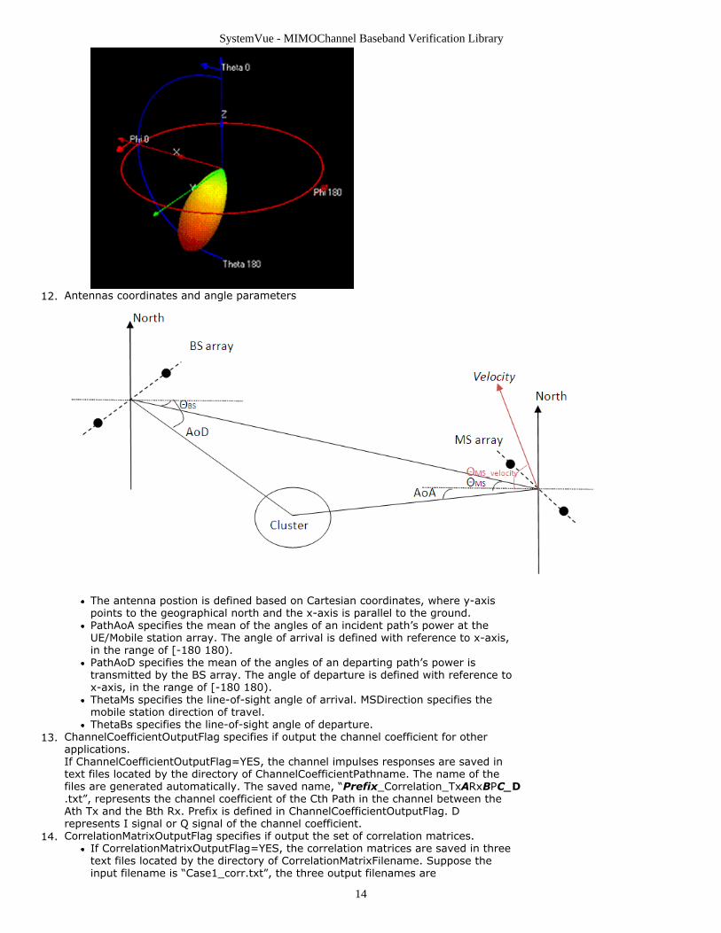
Although this file format is designed for 3D pattern, it also supports 2D pattern.For 2D pattern, in parameter section theta_min should have the same value astheta_max. For 3D pattern, if in the data section, maximum phi=360 ormaximum theta=180, please make sure the phi_max=360, not phi_max=0 andtheat_max=180, not theta_max=0 in the parameter description section.All the phi-theta angles follow the below sphere coordinate. The slice of Theta =90 and Phi from [-180 180] represents the horizontal slice passing the center ofsphere.
SystemVue - MIMOChannel Baseband Verification Library
14
Antennas coordinates and angle parameters12.
The antenna postion is defined based on Cartesian coordinates, where y-axispoints to the geographical north and the x-axis is parallel to the ground.PathAoA specifies the mean of the angles of an incident path’s power at theUE/Mobile station array. The angle of arrival is defined with reference to x-axis,in the range of [-180 180).PathAoD specifies the mean of the angles of an departing path’s power istransmitted by the BS array. The angle of departure is defined with reference tox-axis, in the range of [-180 180).ThetaMs specifies the line-of-sight angle of arrival. MSDirection specifies themobile station direction of travel.ThetaBs specifies the line-of-sight angle of departure.
ChannelCoefficientOutputFlag specifies if output the channel coefficient for other13.applications.If ChannelCoefficientOutputFlag=YES, the channel impulses responses are saved intext files located by the directory of ChannelCoefficientPathname. The name of thefiles are generated automatically. The saved name, “Prefix_Correlation_TxARxBPC_D.txt”, represents the channel coefficient of the Cth Path in the channel between theAth Tx and the Bth Rx. Prefix is defined in ChannelCoefficientOutputFlag. Drepresents I signal or Q signal of the channel coefficient.CorrelationMatrixOutputFlag specifies if output the set of correlation matrices.14.
If CorrelationMatrixOutputFlag=YES, the correlation matrices are saved in threetext files located by the directory of CorrelationMatrixFilename. Suppose theinput filename is “Case1_corr.txt”, the three output filenames are
SystemVue - MIMOChannel Baseband Verification Library
15
“Case1_corr.txt”, “Case1_corr_I.txt” and “Case1_corr_Q.txt”.File “Case1_corr.txt” includes the correlation matrix, MIMO antenna gain andpower imbalance information for all the paths.File “Case1_corr _I.txt” and “Case1_corr_Q.txt” include the correlation matrixthat combines all the paths together, “Case1_corr_I.txt” is the output of the realpart of correlation matrix, “Case1_corr_Q.txt” is the output of the imaginarypart of it. In the two files, the first integer is the number of samples, then thefollowing K ( K=((Number of Tx) x (Number of Rx) )^2 ) float numbers are thereal part (or the imaginary part ) of the correlation matrix .
References
3GPP TSG-RAN WG4 Meeting, Tdoc R4-091361, "MIMO OTA test methodology1.proposal", March 20093GPP TSG-RAN WG4 Meeting, Tdoc R4-091949, "Applying measured MIMO antenna2.patterns to MIMO channel models for OTA analysis", May 2009
SystemVue - MIMOChannel Baseband Verification Library
16
WINNERII_Channel PartCategories: MIMOChannel Category (mimocbasever)
The models associated with this part are listed below. To view detailed information on amodel (description, parameters, equations, notes, etc.), please click the appropriate link.
Model Description
WINNERII_Channel (mimocbasever) Winner II MIMO channel model
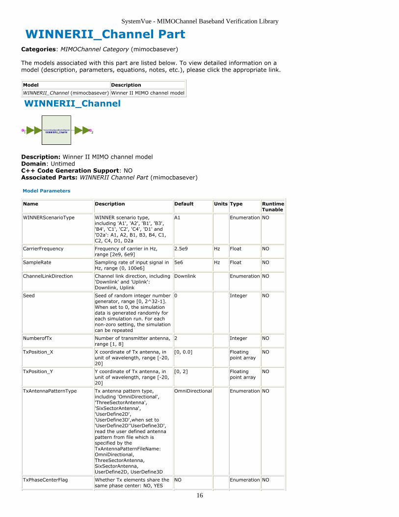
WINNERII_Channel
Description: Winner II MIMO channel modelDomain: UntimedC++ Code Generation Support: NOAssociated Parts: WINNERII Channel Part (mimocbasever)
Model Parameters
Name Description Default Units Type RuntimeTunable
WINNERScenarioType WINNER scenario type,including 'A1', 'A2', 'B1', 'B3','B4', 'C1', 'C2', 'C4', 'D1' and'D2a': A1, A2, B1, B3, B4, C1,C2, C4, D1, D2a
A1 Enumeration NO
CarrierFrequency Frequency of carrier in Hz,range [2e9, 6e9]
2.5e9 Hz Float NO
SampleRate Sampling rate of input signal inHz, range (0, 100e6]
5e6 Hz Float NO
ChannelLinkDirection Channel link direction, including'Downlink' and 'Uplink':Downlink, Uplink
Downlink Enumeration NO
Seed Seed of random integer numbergenerator, range [0, 2^32-1].When set to 0, the simulationdata is generated randomly foreach simulation run. For eachnon-zoro setting, the simulationcan be repeated
0 Integer NO
NumberofTx Number of transmitter antenna,range [1, 8]
2 Integer NO
TxPosition_X X coordinate of Tx antenna, inunit of wavelength, range [-20,20]
[0, 0.0] Floatingpoint array
NO
TxPosition_Y Y coordinate of Tx antenna, inunit of wavelength, range [-20,20]
[0, 2] Floatingpoint array
NO
TxAntennaPatternType Tx antenna pattern type,including 'OmniDirectional','ThreeSectorAntenna','SixSectorAntenna','UserDefine2D','UserDefine3D',when set to'UserDefine2D''UserDefine3D',read the user defined antennapattern from file which isspecified by theTxAntennaPatternFileName:OmniDirectional,ThreeSectorAntenna,SixSectorAntenna,UserDefine2D, UserDefine3D
OmniDirectional Enumeration NO
TxPhaseCenterFlag Whether Tx elements share thesame phase center: NO, YES
NO Enumeration NO

SystemVue - MIMOChannel Baseband Verification Library
17
TxAntennaPatternFileName1 Tx 1 antenna pattern filename Filename NO
TxAntennaPatternFileName2 Tx 2 antenna pattern filename Filename NO
TxAntennaPatternFileName3 Tx 3 antenna pattern filename Filename NO
TxAntennaPatternFileName4 Tx 4 antenna pattern filename Filename NO
TxAntennaPatternFileName5 Tx 5 antenna pattern filename Filename NO
TxAntennaPatternFileName6 Tx 6 antenna pattern filename Filename NO
TxAntennaPatternFileName7 Tx 7 antenna pattern filename Filename NO
TxAntennaPatternFileName8 Tx 8 antenna pattern filename Filename NO
TxRotationAngle Tx roation angle in thehorizontal, in unit of degree,range [-180, 180]
0 Float NO
TxElevationAngle Tx elevation angle, in unit ofdegree, range [0, 180]
90 Float NO
NumberofRx Number of receiver antenna,range [1, 8]
2 Integer NO
RxPosition_X X coordinate of Rx antenna, inunit of wavelength, range [-20,20]
[0, 0.0] Floatingpoint array
NO
RxPosition_Y Y coordinate of Rx antenna, inunit of wavelength, range [-20,20]
[0, 0.5] Floatingpoint array
NO
RxAntennaPatternType Rx antenna pattern type,including 'OmniDirectional','ThreeSectorAntenna','SixSectorAntenna','UserDefine2D','UserDefine3D',when set to'UserDefine2D''UserDefine3D',read the user defined antennapattern from file which isspecified by theRxAntennaPatternFileName:OmniDirectional,ThreeSectorAntenna,SixSectorAntenna,UserDefine2D, UserDefine3D
OmniDirectional Enumeration NO
RxPhaseCenterFlag Whether Rx elements share thesame phase center: NO, YES
NO Enumeration NO
RxAntennaPatternFileName1 Rx 1 antenna pattern filename Filename NO
RxAntennaPatternFileName2 Rx 2 antenna pattern filename Filename NO
RxAntennaPatternFileName3 Rx 3 antenna pattern filename Filename NO
RxAntennaPatternFileName4 Rx 4 antenna pattern filename Filename NO
RxAntennaPatternFileName5 Rx 5 antenna pattern filename Filename NO
RxAntennaPatternFileName6 Rx 6 antenna pattern filename Filename NO
RxAntennaPatternFileName7 Rx 7 antenna pattern filename Filename NO
RxAntennaPatternFileName8 Rx 8 antenna pattern filename Filename NO
RxRotationAngle Rx roation angle in thehorizontal, in unit of degree,range [-180, 180]
0 Float NO
RxElevationAngle Rx elevation angle, in unit ofdegree, range [0, 180]
90 Float NO
ThetaBs Angle between the BS-MS LOSand the BS broadside, in unit ofdegree, range [-180, 180]
0 Float NO
ThetaMs Angle between the BS-MS LOSand the MS broadside, in unit ofdegree, range [-180, 180]
0 Float NO
MSVelocity Mobile station velocity (km/h),range [0, 200]
50 Float NO
MSDirection Mobile station moving direction(degree), [-180, 180]
30 Float NO
DropInterval Drop interval in second, duringthis time segment, all the large-scale parameters are constant.Range [0.001, inf)
0.05 s Float NO
UseFixedCDLParameter Whether use fixed CDLparameter: NO, YES
YES Enumeration NO
UsePolarise Whether use dual polarise: NO, NO Enumeration NO

SystemVue - MIMOChannel Baseband Verification Library
18
YES
UseShadowModel Whether use shadow model:NO, YES
NO Enumeration NO
UseManualPropCond Whether use manualpropagation condition: NO, YES
NO Enumeration NO
UseLOS Propagation condition, couplingwith UseManualPropCond, onlywhen UseManualPropCode istrue, this option can take effect.And when'WINNERScenarioType' is A2, B4or C4, this option should only beNO, when'WINNERScenarioType' is D2a,this option should only be YES.:NO, YES
NO Enumeration NO
UseIntraClusterDelays Whether use intra cluster delaysflag: NO, YES
NO Enumeration NO
UsePathLossModel Whether use path loss model:NO, YES
NO Enumeration NO
BsHeight Bs antenna height, in unit of m,range [0, 50]
25 m Float NO
MsHeight Ms antenna height, in unit of m,range [0, 50]
1.5 m Float NO
MsBsDistance The distance between Ms andBs, in unit of m, different rangesfor different scenerios, for A1[3:100]
10 m Float NO
NLOS_Scenario Optional NLOS scenario for A1,including 'CR_light', 'CR_heavy','RR_light' and 'RR_heavy',coupling withChannelFadingModel andWINNERScenerio, only forWINNER A1 scenerio, need thisoption: CR_light, CR_heavy,RR_light, RR_heavy
CR_light Enumeration NO
NumPenetratedFloor Number of floor between BS/MSfor the scenario A1 path loss,range [1, 10]
1 Integer NO
NumWalls Number of walls for the scenarioA1 path loss, range [1, 10]
1 Integer NO
StreetWidth Width of street for scenariosA2/B4 path loss, in m, range[10, 50]
20 Float NO
Perpendicular_Distance Distance from BS to the streetcrossing for scenarioA2/B1/B4/C4 path loss, in unitof m, range (0,MsBsDistance)
5 m Float NO
ChannelCoefficientOutputFlag Whether output channelcoefficient to files: NO, YES
NO Enumeration NO
ChannelCoefficientPathname Channel coefficient outputpathname, the pathname shouldbe end with '\', the output fileswill be output in this directory,with the name'DropXTxYRxZPW.bin', which X,Y, Z and W are the drop No, TxNo, Rx No and path Norespectively.
Filename NO
CorrelationMatrixOutputFlag Whether output correlationmatrix to files: NO, YES
NO Enumeration NO
CorrelationMatrixFilename Correlation matrix outputfilename
Filename NO
Input Ports
Port Name Signal Type Optional
1 TransmittingSignals multiple complex NO
Output Ports
SystemVue - MIMOChannel Baseband Verification Library
19
Port Name Signal Type Optional
2 FadedSignals multiple complex NO
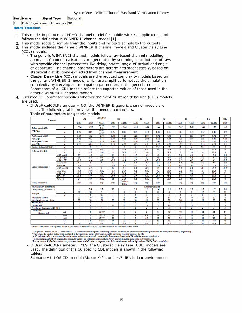
Notes/Equations
This model implements a MIMO channel model for mobile wireless applications and1.follows the definition in WINNER II channel model [1].This model reads 1 sample from the inputs and writes 1 sample to the outputs.2.This model includes the generic WINNER II channel models and Cluster Delay Line3.(CDL) models.
The generic WINNER II channel models follow ray-based channel modellingapproach. Channel realisations are generated by summing contributions of rayswith specific channel parameters like delay, power, angle-of-arrival and angle-of-departure. The channel parameters are determined stochasticaly, based onstatistical distributions extracted from channel measurement.Cluster Delay Line (CDL) models are the reduced complexity models based onthe generic WINNER II models, which are simplified to reduce the simulationcomplexity by freezing all propagation parameters in the generic models.Parameters of all CDL models reflect the expected values of those used in thegeneric WINNER II channel models.
UseFixedCDLParameter specifies whether the fixed clustered delay line (CDL) models4.are used.
If UseFixedCDLParameter = NO, the WINNER II generic channel models areused. The following table provides the needed parameters.Table of parameters for generic models
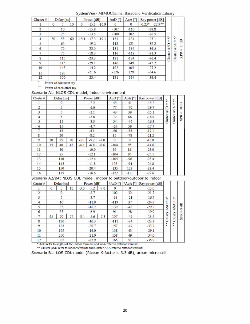
If UseFixedCDLParameter = YES, the Clustered Delay Line (CDL) models areused. The definition of the 16 specific CDL models is shown in the followingtables:Scenario A1: LOS CDL model (Ricean K-factor is 4.7 dB), indoor environment
SystemVue - MIMOChannel Baseband Verification Library
20
Scenario A1: NLOS CDL model, indoor environment
Scenario A2/B4: NLOS CDL model, indoor to outdoor/outdoor to indoor
Scenario B1: LOS CDL model (Ricean K-factor is 3.3 dB), urban micro-cell

SystemVue - MIMOChannel Baseband Verification Library
21
Scenario B1: NLOS CDL model, urban micro-cell
Scenario B3: LOS CDL model (Ricean K-factor is 2 dB), indoor hotspot
Scenario B3: NLOS CDL model, indoor hotspot
SystemVue - MIMOChannel Baseband Verification Library
22
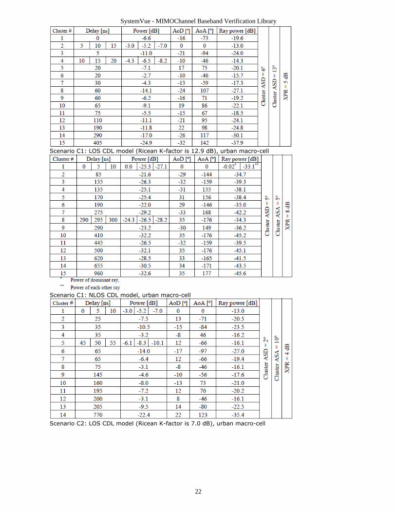
Scenario C1: LOS CDL model (Ricean K-factor is 12.9 dB), urban macro-cell
Scenario C1: NLOS CDL model, urban macro-cell
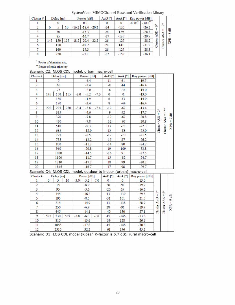
Scenario C2: LOS CDL model (Ricean K-factor is 7.0 dB), urban macro-cell
SystemVue - MIMOChannel Baseband Verification Library
23
Scenario C2: NLOS CDL model, urban macro-cell
Scenario C4: NLOS CDL model, outdoor to indoor (urban) macro-cell
Scenario D1: LOS CDL model (Ricean K-factor is 5.7 dB), rural macro-cell

SystemVue - MIMOChannel Baseband Verification Library
24
Scenario D1: NLOS CDL model, rural macro-cell
Scenario D2a: LOS CDL model (Ricean K-factor is 7 dB), moving networks
UseShadowModel specifies whether the shadow effect is included.5.UsePolarise specifies whether the polarization effect is included.6.
If UsePolarise=NO, only vertically polarized field patterns is applied.If UsePolarise=YES, the antenna element field patterns for vertical andhorizontal polarizations are applied.
UseIntraClusterDelays specifies whether the intra cluster delays are introduced in the7.two strongest clusters. Introducing intra cluster delay spread increases effectivebandwidth of the model.
If UseIntraClusterDelays = NO, number of rays per cluster is fixed to 20.If UseIntraClusterDelays = YES, twenty rays of the two strongest clusters aremapped to sub-clusters in the way shown in the following table.
UseManualPropCond specifies how to identify the NLOS/LOS propagation condition.8.For scenarios A2, B4, C4, the LOS probability is set zero. For scenario D2a, the LOSprobability is set one. For the remaining scenarios, there are two options:
If UseManualPropCond = YES, the WINNER channel model provides the option todetermine the existence of NLOS/LOS propagation conditions deterministically
SystemVue - MIMOChannel Baseband Verification Library
25
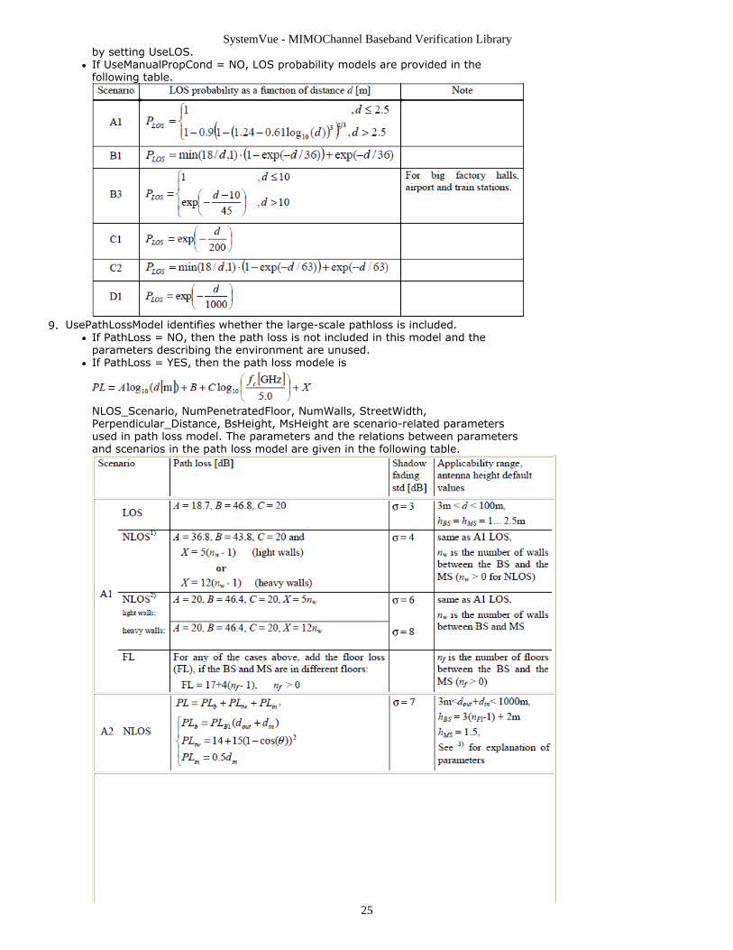
by setting UseLOS.If UseManualPropCond = NO, LOS probability models are provided in thefollowing table.
UsePathLossModel identifies whether the large-scale pathloss is included.9.If PathLoss = NO, then the path loss is not included in this model and theparameters describing the environment are unused.If PathLoss = YES, then the path loss modele is
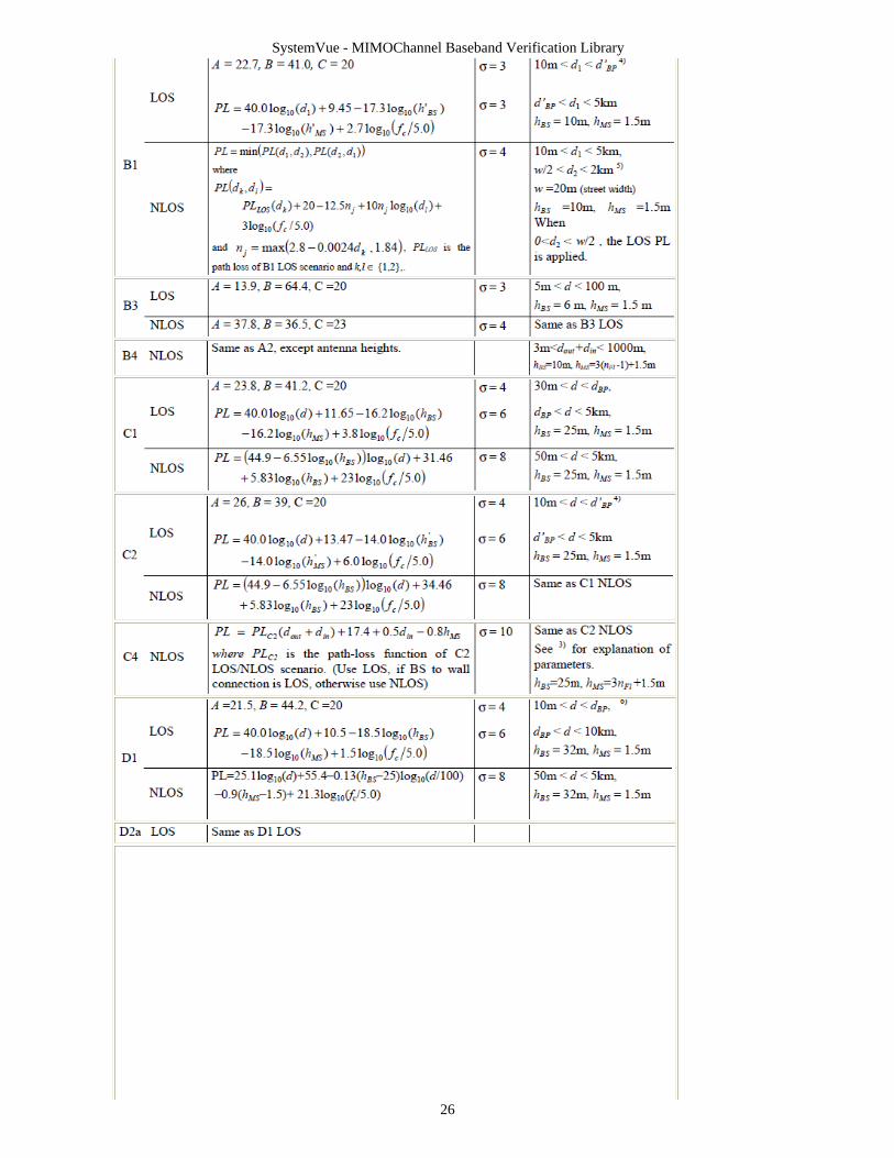
NLOS_Scenario, NumPenetratedFloor, NumWalls, StreetWidth,Perpendicular_Distance, BsHeight, MsHeight are scenario-related parametersused in path loss model. The parameters and the relations between parametersand scenarios in the path loss model are given in the following table.
SystemVue - MIMOChannel Baseband Verification Library
26
SystemVue - MIMOChannel Baseband Verification Library
27
DropInterval specifies the duration time in which probability distributions of small-10.scale parameters are not changed noticeably. During this period of quasi-stationarityall large-scale parameters are paractically constant.RxPhiRotation and TxPhiRotation are the Rx/Tx rotation angle in the horizontal, in11.degree, the range is [-180, 180].RxElevationAngle and TxElevationAngle are the Rx/Tx elevation angle, in degree, the12.range is [0, 180].If TxAntennaPatternType (or RxAntennaPatternType)= UserDefine2D or13.UserDefine3D , antenna pattern files named by TxAntennaPatternFileNameX (orRxAntennaPatternFileNameX) are loaded, each Rx/Tx element has an individualantenna pattern filename input, X represents the Xth antenna’s pattern . The user-defined antenna pattern file format almost completely follows Agilent Empro 3D far-zone files, but with more flexibility and extension ability:
Each antenna’s pattern is saved in one separated file. The file format consists oftwo parts, a parameters description section and a data section. The parametersshould be self-explanatory. They are explained in below each line. Theparameters section will look like the following:
begin_<parameters>format free // can be others in the future for extensionphi_min 0 // the minimum phi angle to save in the filephi_max 360 // the maximum phi angle to save in the filephi_inc 5 // the increasing step for phi, the phi sampling points should beequal separationtheta_min 0 // the minimum theta angle to save in the filetheta_max 180 // the minimum theta angle to save in the filetheta_inc 5 // the increasing step for phi, the theta sampling points shouldbe equal separationcomplex // antenna gain is complexmag_phase // the data file is given in magnitude - phase style or in real-imaginary stylepattern gain // pattern is given in gainmagnitude dB // magnitude is given in linear or in dBdirection degrees //phi and theta are given in degrees or radiansphase degrees // phase is given in degrees or in radianspolarization theta_phi // polarization type, theta_phi means vertical andhorizontal polarizationNetInputPower 0.002482195 // by now this parameter is not used incurrent codeend_<parameters>
After the parameters section will follow a data section. This section is delimitedby the end of file marker. There will be up to 6 columns of data in this section.
If use “mag_phase” type, it should be in the following order:Theta-angle // degrees or radians, determined by parameter“direction”Phi-angle // degrees or radians, determined by parameter “direction”Theta-gain // dB or linear, determined by parameter “magnitude”Phi-gain // dB or linear, determined by parameter “magnitude”
SystemVue - MIMOChannel Baseband Verification Library
28
Theta-Phase // degrees or radians, determined by parameter “phase”Phi-Phase //degrees or radians, determined by parameter “phase”
If use “real_imag” type, it should be in the following order:Theta-angle //degrees or radians, determined by parameter“direction”Phi-angle //degrees or radians, determined by parameter “direction”Real part of Theta-gainImaginary part of Theta-gainReal part of Phi-gainImaginary part of Phi-gain
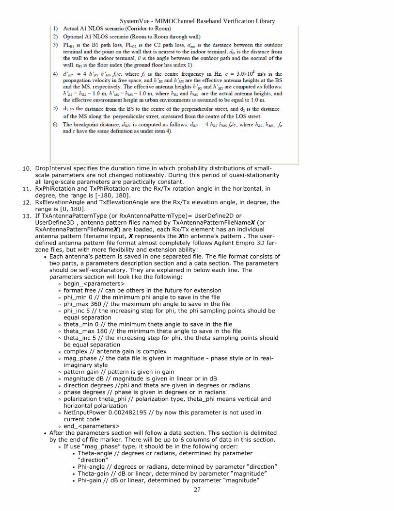
Although this file format is designed for 3D pattern, it also supports 2D pattern.For 2D pattern, in parameter section theta_min should have the same value astheta_max. For 3D pattern, if in the data section, maximum phi=360 ormaximum theta=180, please make sure the phi_max=360, not phi_max=0 andtheat_max=180, not theta_max=0 in the parameter description section.All the phi-theta angles follow the below sphere coordinate. The slice of Theta =90 and Phi from [-180 180] represents the horizontal slice passing the center ofsphere.
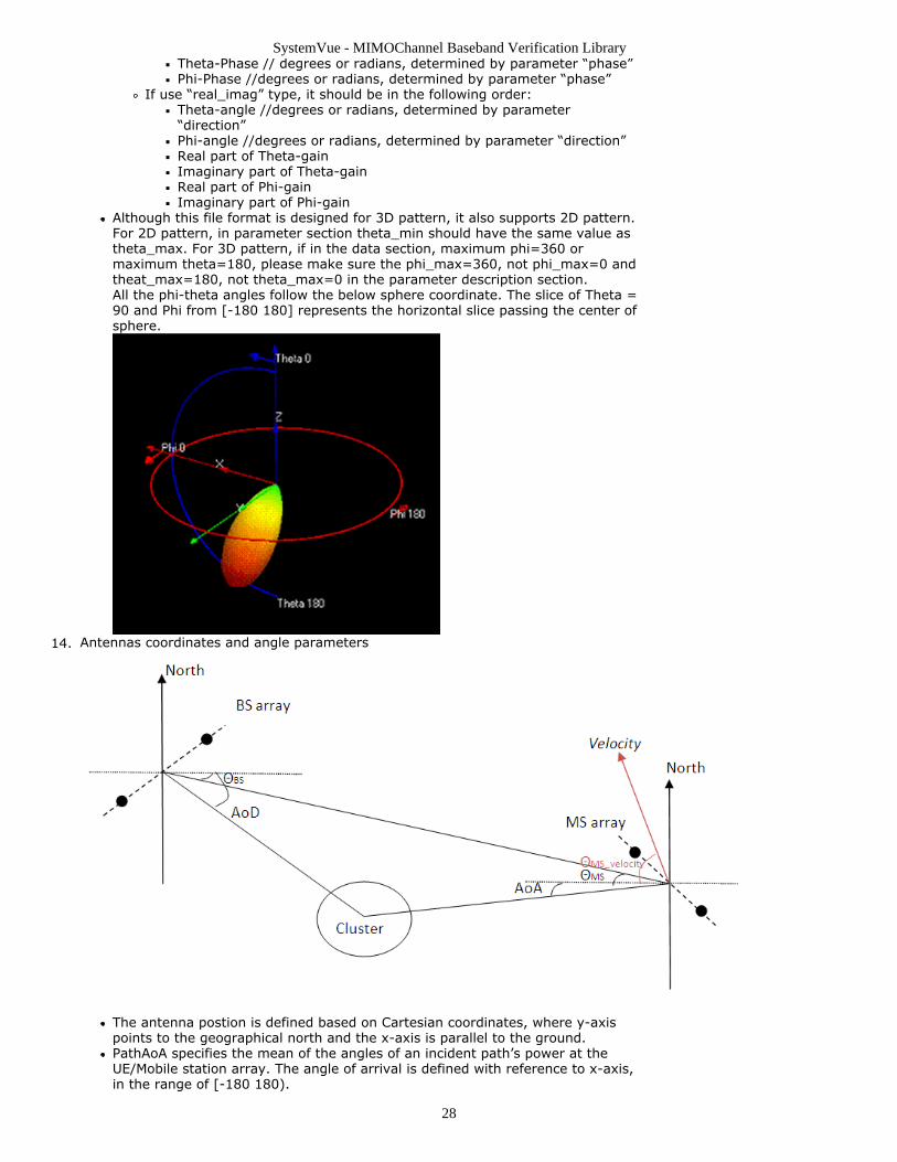
Antennas coordinates and angle parameters14.
The antenna postion is defined based on Cartesian coordinates, where y-axispoints to the geographical north and the x-axis is parallel to the ground.PathAoA specifies the mean of the angles of an incident path’s power at theUE/Mobile station array. The angle of arrival is defined with reference to x-axis,in the range of [-180 180).
SystemVue - MIMOChannel Baseband Verification Library
29
PathAoD specifies the mean of the angles of an departing path’s power istransmitted by the BS array. The angle of departure is defined with reference tox-axis, in the range of [-180 180).ThetaMs specifies the line-of-sight angle of arrival. MSDirection specifies themobile station direction of travel.ThetaBs specifies the line-of-sight angle of departure.
ChannelCoefficientOutputFlag specifies if output the channel coefficient for other15.applications.If ChannelCoefficientOutputFlag=YES, the channel impulses responses are saved intext files located by the directory of ChannelCoefficientPathname. The name of thefiles are generated automatically. The saved name, “Prefix_WINNERII_DropATxBRxCPD_E.txt”, represents the channel coefficient of the Dth Path in the channel betweenthe Bth Tx and the Cth Rx in the Ath drop. Prefix is defined inChannelCoefficientOutputFlag. E represents I signal or Q signal of the channelcoefficient.CorrelationMatrixOutputFlag specifies if output the set of correlation matrices.16.
If CorrelationMatrixOutputFlag=YES, the correlation matrices are saved in threetext files located by the directory of CorrelationMatrixFilename. Suppose theinput filename is “Case1_winner.txt”, the three output filenames are“Case1_winner.txt”, “Case1_winner_I.txt” and “Case1_winner_Q.txt”.File “Case1_winner.txt” includes the correlation matrix, MIMO antenna gain andpower imbalance information for all the paths and all the drops.File “Case1_winner _I.txt” and “Case1_winner_Q.txt” include the correlationmatrix that combines all the paths together, “Case1_winner_I.txt” is the outputof the real part of correlation matrix, “Case1_winner_Q.txt” is the output of theimaginary part of it. In the two files, the first integer is the number of samplesof the first drop, then the following K ( K=((Number of Tx) x (Number of Rx))^2 ) float numbers are the real part (or the imaginary part ) of the correlationmatrix of drop 1. After this, another integer which is the number of samples ofdrop 2 follows, then the K float numbers of the real part (or the imaginary part)of correlation matrix of drop 2 follows, and etc.
References
IST-4-027756 WINNER II D1.1.2, "WINNER II Channel Models", ver 1.2, Sep. 20071.