cdma baseband verification library
TRANSCRIPT


CDMA Baseband Verification Library
1
SystemVue 2011.102011
CDMA Baseband Verification Library

CDMA Baseband Verification Library
2
© Agilent Technologies, Inc. 2000-2010395 Page Mill Road, Palo Alto, CA 94304 U.S.A.No part of this manual may be reproduced in any form or by any means (includingelectronic storage and retrieval or translation into a foreign language) without prioragreement and written consent from Agilent Technologies, Inc. as governed by UnitedStates and international copyright laws.
Acknowledgments Mentor Graphics is a trademark of Mentor Graphics Corporation inthe U.S. and other countries. Microsoft®, Windows®, MS Windows®, Windows NT®, andMS-DOS® are U.S. registered trademarks of Microsoft Corporation. Pentium® is a U.S.registered trademark of Intel Corporation. PostScript® and Acrobat® are trademarks ofAdobe Systems Incorporated. UNIX® is a registered trademark of the Open Group. Java™is a U.S. trademark of Sun Microsystems, Inc. SystemC® is a registered trademark ofOpen SystemC Initiative, Inc. in the United States and other countries and is used withpermission. MATLAB® is a U.S. registered trademark of The Math Works, Inc.. HiSIM2source code, and all copyrights, trade secrets or other intellectual property rights in and tothe source code in its entirety, is owned by Hiroshima University and STARC.
Errata The SystemVue product may contain references to "HP" or "HPEESOF" such as infile names and directory names. The business entity formerly known as "HP EEsof" is nowpart of Agilent Technologies and is known as "Agilent EEsof". To avoid broken functionalityand to maintain backward compatibility for our customers, we did not change all thenames and labels that contain "HP" or "HPEESOF" references.
Warranty The material contained in this document is provided "as is", and is subject tobeing changed, without notice, in future editions. Further, to the maximum extentpermitted by applicable law, Agilent disclaims all warranties, either express or implied,with regard to this manual and any information contained herein, including but not limitedto the implied warranties of merchantability and fitness for a particular purpose. Agilentshall not be liable for errors or for incidental or consequential damages in connection withthe furnishing, use, or performance of this document or of any information containedherein. Should Agilent and the user have a separate written agreement with warrantyterms covering the material in this document that conflict with these terms, the warrantyterms in the separate agreement shall control.
Technology Licenses The hardware and/or software described in this document arefurnished under a license and may be used or copied only in accordance with the terms ofsuch license.
Portions of this product is derivative work based on the University of California PtolemySoftware System.
In no event shall the University of California be liable to any party for direct, indirect,special, incidental, or consequential damages arising out of the use of this software and itsdocumentation, even if the University of California has been advised of the possibility ofsuch damage.
The University of California specifically disclaims any warranties, including, but not limitedto, the implied warranties of merchantability and fitness for a particular purpose. Thesoftware provided hereunder is on an "as is" basis and the University of California has noobligation to provide maintenance, support, updates, enhancements, or modifications.
Portions of this product include code developed at the University of Maryland, for theseportions the following notice applies.
In no event shall the University of Maryland be liable to any party for direct, indirect,special, incidental, or consequential damages arising out of the use of this software and itsdocumentation, even if the University of Maryland has been advised of the possibility ofsuch damage.

CDMA Baseband Verification Library
3
The University of Maryland specifically disclaims any warranties, including, but not limitedto, the implied warranties of merchantability and fitness for a particular purpose. thesoftware provided hereunder is on an "as is" basis, and the University of Maryland has noobligation to provide maintenance, support, updates, enhancements, or modifications.
Portions of this product include the SystemC software licensed under Open Source terms,which are available for download at http://systemc.org/ . This software is redistributed byAgilent. The Contributors of the SystemC software provide this software "as is" and offerno warranty of any kind, express or implied, including without limitation warranties orconditions or title and non-infringement, and implied warranties or conditionsmerchantability and fitness for a particular purpose. Contributors shall not be liable forany damages of any kind including without limitation direct, indirect, special, incidentaland consequential damages, such as lost profits. Any provisions that differ from thisdisclaimer are offered by Agilent only.With respect to the portion of the Licensed Materials that describes the software andprovides instructions concerning its operation and related matters, "use" includes the rightto download and print such materials solely for the purpose described above.
Restricted Rights Legend If software is for use in the performance of a U.S.Government prime contract or subcontract, Software is delivered and licensed as"Commercial computer software" as defined in DFAR 252.227-7014 (June 1995), or as a"commercial item" as defined in FAR 2.101(a) or as "Restricted computer software" asdefined in FAR 52.227-19 (June 1987) or any equivalent agency regulation or contractclause. Use, duplication or disclosure of Software is subject to Agilent Technologies´standard commercial license terms, and non-DOD Departments and Agencies of the U.S.Government will receive no greater than Restricted Rights as defined in FAR 52.227-19(c)(1-2) (June 1987). U.S. Government users will receive no greater than LimitedRights as defined in FAR 52.227-14 (June 1987) or DFAR 252.227-7015 (b)(2) (November1995), as applicable in any technical data.

CDMA Baseband Verification Library
4
About CDMA Baseband Verification Library . . . . . . . . . . . . . . . . . . . . . . . . . . . . . . . . . . . . . . 6 CDMA CELP Codecs Category . . . . . . . . . . . . . . . . . . . . . . . . . . . . . . . . . . . . . . . . . . . . . . . . 7
CDMA_Autocorrelation Part . . . . . . . . . . . . . . . . . . . . . . . . . . . . . . . . . . . . . . . . . . . . . . . . 8 CDMA_CelpSubCoder Part . . . . . . . . . . . . . . . . . . . . . . . . . . . . . . . . . . . . . . . . . . . . . . . . 10 CDMA_CelpSubDecoder Part . . . . . . . . . . . . . . . . . . . . . . . . . . . . . . . . . . . . . . . . . . . . . . . 12 CDMA_DataPack Part . . . . . . . . . . . . . . . . . . . . . . . . . . . . . . . . . . . . . . . . . . . . . . . . . . . . 14 CDMA_DataUnPack Part . . . . . . . . . . . . . . . . . . . . . . . . . . . . . . . . . . . . . . . . . . . . . . . . . . 16 CDMA_DurbinRecursion Part . . . . . . . . . . . . . . . . . . . . . . . . . . . . . . . . . . . . . . . . . . . . . . . 18 CDMA_FormantFilter Part . . . . . . . . . . . . . . . . . . . . . . . . . . . . . . . . . . . . . . . . . . . . . . . . . 19 CDMA_GainPostFilter Part . . . . . . . . . . . . . . . . . . . . . . . . . . . . . . . . . . . . . . . . . . . . . . . . . 21 CDMA_HammingWindow Part . . . . . . . . . . . . . . . . . . . . . . . . . . . . . . . . . . . . . . . . . . . . . . 23 CDMA_LPC_ToLSP Part . . . . . . . . . . . . . . . . . . . . . . . . . . . . . . . . . . . . . . . . . . . . . . . . . . 25 CDMA_LSP_ToLPC Part . . . . . . . . . . . . . . . . . . . . . . . . . . . . . . . . . . . . . . . . . . . . . . . . . . 27 CDMA_PitchCdbkSelector Part . . . . . . . . . . . . . . . . . . . . . . . . . . . . . . . . . . . . . . . . . . . . . . 29 CDMA_PitchFilter Part . . . . . . . . . . . . . . . . . . . . . . . . . . . . . . . . . . . . . . . . . . . . . . . . . . . 32 CDMA_QuantizerWi Part . . . . . . . . . . . . . . . . . . . . . . . . . . . . . . . . . . . . . . . . . . . . . . . . . . 34 CDMA_ReadSigFile Part . . . . . . . . . . . . . . . . . . . . . . . . . . . . . . . . . . . . . . . . . . . . . . . . . . 36 CDMA_RemoveDC Part . . . . . . . . . . . . . . . . . . . . . . . . . . . . . . . . . . . . . . . . . . . . . . . . . . . 37 CDMA_ScaledCdbkVector Part . . . . . . . . . . . . . . . . . . . . . . . . . . . . . . . . . . . . . . . . . . . . . . 38 CDMA_UnquantizerWi Part . . . . . . . . . . . . . . . . . . . . . . . . . . . . . . . . . . . . . . . . . . . . . . . . 39 CDMA_VariableDataRate Part . . . . . . . . . . . . . . . . . . . . . . . . . . . . . . . . . . . . . . . . . . . . . . 40 CDMA_WriteSigFile Part . . . . . . . . . . . . . . . . . . . . . . . . . . . . . . . . . . . . . . . . . . . . . . . . . . 42
CDMA Channel Codecs Category . . . . . . . . . . . . . . . . . . . . . . . . . . . . . . . . . . . . . . . . . . . . . . 43 CDMA_AccessDeintlvr Part . . . . . . . . . . . . . . . . . . . . . . . . . . . . . . . . . . . . . . . . . . . . . . . . 44 CDMA_AccessIntlvr Part . . . . . . . . . . . . . . . . . . . . . . . . . . . . . . . . . . . . . . . . . . . . . . . . . . 46 CDMA_AddTail Part . . . . . . . . . . . . . . . . . . . . . . . . . . . . . . . . . . . . . . . . . . . . . . . . . . . . . 47 CDMA_BitCC Part . . . . . . . . . . . . . . . . . . . . . . . . . . . . . . . . . . . . . . . . . . . . . . . . . . . . . . 48 CDMA_CC_WithTail Part . . . . . . . . . . . . . . . . . . . . . . . . . . . . . . . . . . . . . . . . . . . . . . . . . . 50 CDMA_DCC_WithTail Part . . . . . . . . . . . . . . . . . . . . . . . . . . . . . . . . . . . . . . . . . . . . . . . . . 52 CDMA_EraseTail Part . . . . . . . . . . . . . . . . . . . . . . . . . . . . . . . . . . . . . . . . . . . . . . . . . . . . 54 CDMA_ErrorRate Part . . . . . . . . . . . . . . . . . . . . . . . . . . . . . . . . . . . . . . . . . . . . . . . . . . . . 55 CDMA_FwdChCoder Part . . . . . . . . . . . . . . . . . . . . . . . . . . . . . . . . . . . . . . . . . . . . . . . . . 56 CDMA_FwdChDecoder Part . . . . . . . . . . . . . . . . . . . . . . . . . . . . . . . . . . . . . . . . . . . . . . . . 58 CDMA_FwdViterbiDCC Part . . . . . . . . . . . . . . . . . . . . . . . . . . . . . . . . . . . . . . . . . . . . . . . . 60 CDMA_LogicToNRZ Part . . . . . . . . . . . . . . . . . . . . . . . . . . . . . . . . . . . . . . . . . . . . . . . . . . 62 CDMA_OneBitQuantizer Part . . . . . . . . . . . . . . . . . . . . . . . . . . . . . . . . . . . . . . . . . . . . . . . 64 CDMA_OneWayVD Part . . . . . . . . . . . . . . . . . . . . . . . . . . . . . . . . . . . . . . . . . . . . . . . . . . 65 CDMA_PgFwdTrfDeintlvr Part . . . . . . . . . . . . . . . . . . . . . . . . . . . . . . . . . . . . . . . . . . . . . . 67 CDMA_PgFwdTrfIntlvr Part . . . . . . . . . . . . . . . . . . . . . . . . . . . . . . . . . . . . . . . . . . . . . . . . 69 CDMA_Repeat Part . . . . . . . . . . . . . . . . . . . . . . . . . . . . . . . . . . . . . . . . . . . . . . . . . . . . . 70 CDMA_RevChCoder Part . . . . . . . . . . . . . . . . . . . . . . . . . . . . . . . . . . . . . . . . . . . . . . . . . . 73 CDMA_RevChDecoder Part . . . . . . . . . . . . . . . . . . . . . . . . . . . . . . . . . . . . . . . . . . . . . . . . 75 CDMA_RevOneway Part . . . . . . . . . . . . . . . . . . . . . . . . . . . . . . . . . . . . . . . . . . . . . . . . . . 77 CDMA_RevTrfDeintlvr Part . . . . . . . . . . . . . . . . . . . . . . . . . . . . . . . . . . . . . . . . . . . . . . . . 79 CDMA_RevTrfIntlvr Part . . . . . . . . . . . . . . . . . . . . . . . . . . . . . . . . . . . . . . . . . . . . . . . . . . 81 CDMA_SyncDeintlvr Part . . . . . . . . . . . . . . . . . . . . . . . . . . . . . . . . . . . . . . . . . . . . . . . . . 82 CDMA_SyncIntlvr Part . . . . . . . . . . . . . . . . . . . . . . . . . . . . . . . . . . . . . . . . . . . . . . . . . . . 84 CDMA_TrffcFrmGen Part . . . . . . . . . . . . . . . . . . . . . . . . . . . . . . . . . . . . . . . . . . . . . . . . . . 85 CDMA_TrffcFrmRcvry Part . . . . . . . . . . . . . . . . . . . . . . . . . . . . . . . . . . . . . . . . . . . . . . . . 89 CDMA_VariableRateCC Part . . . . . . . . . . . . . . . . . . . . . . . . . . . . . . . . . . . . . . . . . . . . . . . 91 CDMA_VariableRateDCC Part . . . . . . . . . . . . . . . . . . . . . . . . . . . . . . . . . . . . . . . . . . . . . . 93 CDMA_ViterbiBitDCC Part . . . . . . . . . . . . . . . . . . . . . . . . . . . . . . . . . . . . . . . . . . . . . . . . . 96
CDMA Channel Model Category . . . . . . . . . . . . . . . . . . . . . . . . . . . . . . . . . . . . . . . . . . . . . . 99 CDMA_Channel Part . . . . . . . . . . . . . . . . . . . . . . . . . . . . . . . . . . . . . . . . . . . . . . . . . . . . . 100
CDMA Receivers Category . . . . . . . . . . . . . . . . . . . . . . . . . . . . . . . . . . . . . . . . . . . . . . . . . . 104 CDMA_BSFinger Part . . . . . . . . . . . . . . . . . . . . . . . . . . . . . . . . . . . . . . . . . . . . . . . . . . . . 105 CDMA_BSRake Part . . . . . . . . . . . . . . . . . . . . . . . . . . . . . . . . . . . . . . . . . . . . . . . . . . . . . 108 CDMA_BSRateconverter Part . . . . . . . . . . . . . . . . . . . . . . . . . . . . . . . . . . . . . . . . . . . . . . 110 CDMA_BSSearcher Part . . . . . . . . . . . . . . . . . . . . . . . . . . . . . . . . . . . . . . . . . . . . . . . . . . 111

CDMA Baseband Verification Library
5
CDMA_CoherentRake Part . . . . . . . . . . . . . . . . . . . . . . . . . . . . . . . . . . . . . . . . . . . . . . . . 115 CDMA_FreqErrEstimate Part . . . . . . . . . . . . . . . . . . . . . . . . . . . . . . . . . . . . . . . . . . . . . . . 117 CDMA_FreqShifter Part . . . . . . . . . . . . . . . . . . . . . . . . . . . . . . . . . . . . . . . . . . . . . . . . . . 120 CDMA_FwdChnlSounder Part . . . . . . . . . . . . . . . . . . . . . . . . . . . . . . . . . . . . . . . . . . . . . . 122 CDMA_FwdRake Part . . . . . . . . . . . . . . . . . . . . . . . . . . . . . . . . . . . . . . . . . . . . . . . . . . . . 125 CDMA_FwdRcvwithAFC Part . . . . . . . . . . . . . . . . . . . . . . . . . . . . . . . . . . . . . . . . . . . . . . . 127 CDMA_FwdRcvwithoutAFC Part . . . . . . . . . . . . . . . . . . . . . . . . . . . . . . . . . . . . . . . . . . . . . 129 CDMA_PathCombiner Part . . . . . . . . . . . . . . . . . . . . . . . . . . . . . . . . . . . . . . . . . . . . . . . . 131 CDMA_PnCodeAcq Part . . . . . . . . . . . . . . . . . . . . . . . . . . . . . . . . . . . . . . . . . . . . . . . . . . 134 CDMA_PnCodeTrack Part . . . . . . . . . . . . . . . . . . . . . . . . . . . . . . . . . . . . . . . . . . . . . . . . . 138 CDMA_RevAGC Part . . . . . . . . . . . . . . . . . . . . . . . . . . . . . . . . . . . . . . . . . . . . . . . . . . . . . 142
CDMA Test Category . . . . . . . . . . . . . . . . . . . . . . . . . . . . . . . . . . . . . . . . . . . . . . . . . . . . . . 143 CDMA_AWGN_Ch Part . . . . . . . . . . . . . . . . . . . . . . . . . . . . . . . . . . . . . . . . . . . . . . . . . . . 144 CDMA_BER Part . . . . . . . . . . . . . . . . . . . . . . . . . . . . . . . . . . . . . . . . . . . . . . . . . . . . . . . 145 CDMA_BER_Sink Part . . . . . . . . . . . . . . . . . . . . . . . . . . . . . . . . . . . . . . . . . . . . . . . . . . . . 147 CDMA_CC_215 Part . . . . . . . . . . . . . . . . . . . . . . . . . . . . . . . . . . . . . . . . . . . . . . . . . . . . . 149 CDMA_CycCodeEncoder Part . . . . . . . . . . . . . . . . . . . . . . . . . . . . . . . . . . . . . . . . . . . . . . . 151 CDMA_Cyc Part . . . . . . . . . . . . . . . . . . . . . . . . . . . . . . . . . . . . . . . . . . . . . . . . . . . . . . . . 152 CDMA_Cyc_R12 Part . . . . . . . . . . . . . . . . . . . . . . . . . . . . . . . . . . . . . . . . . . . . . . . . . . . . 154 CDMA_DeOQPSK Part . . . . . . . . . . . . . . . . . . . . . . . . . . . . . . . . . . . . . . . . . . . . . . . . . . . 156 CDMA_Fwd Part . . . . . . . . . . . . . . . . . . . . . . . . . . . . . . . . . . . . . . . . . . . . . . . . . . . . . . . 158 CDMA_FwdTrfCh Part . . . . . . . . . . . . . . . . . . . . . . . . . . . . . . . . . . . . . . . . . . . . . . . . . . . . 160 CDMA_IncSource Part . . . . . . . . . . . . . . . . . . . . . . . . . . . . . . . . . . . . . . . . . . . . . . . . . . . 162 CDMA_OQPSK Part . . . . . . . . . . . . . . . . . . . . . . . . . . . . . . . . . . . . . . . . . . . . . . . . . . . . . 163 CDMA_PN_Code Part . . . . . . . . . . . . . . . . . . . . . . . . . . . . . . . . . . . . . . . . . . . . . . . . . . . . 165 CDMA_Sounder_Statistic Part . . . . . . . . . . . . . . . . . . . . . . . . . . . . . . . . . . . . . . . . . . . . . . 167 CDMA_TimeAverage Part . . . . . . . . . . . . . . . . . . . . . . . . . . . . . . . . . . . . . . . . . . . . . . . . . 169 CDMA_TrfER Part . . . . . . . . . . . . . . . . . . . . . . . . . . . . . . . . . . . . . . . . . . . . . . . . . . . . . . 170 CDMA_TriffERR Part . . . . . . . . . . . . . . . . . . . . . . . . . . . . . . . . . . . . . . . . . . . . . . . . . . . . . 172 CDMA_TstSrc Part . . . . . . . . . . . . . . . . . . . . . . . . . . . . . . . . . . . . . . . . . . . . . . . . . . . . . . 173
CDMA Transmission Category . . . . . . . . . . . . . . . . . . . . . . . . . . . . . . . . . . . . . . . . . . . . . . . . 174 CDMA_BSTX Part . . . . . . . . . . . . . . . . . . . . . . . . . . . . . . . . . . . . . . . . . . . . . . . . . . . . . . . 175 CDMA_DataRandomizer Part . . . . . . . . . . . . . . . . . . . . . . . . . . . . . . . . . . . . . . . . . . . . . . . 176 CDMA_LongCodeGenerator Part . . . . . . . . . . . . . . . . . . . . . . . . . . . . . . . . . . . . . . . . . . . . 178 CDMA_M_aryModulator Part . . . . . . . . . . . . . . . . . . . . . . . . . . . . . . . . . . . . . . . . . . . . . . . 180 CDMA_MSTX Part . . . . . . . . . . . . . . . . . . . . . . . . . . . . . . . . . . . . . . . . . . . . . . . . . . . . . . 181 CDMA_MUX Part . . . . . . . . . . . . . . . . . . . . . . . . . . . . . . . . . . . . . . . . . . . . . . . . . . . . . . . 183 CDMA_PCBitExtraction Part . . . . . . . . . . . . . . . . . . . . . . . . . . . . . . . . . . . . . . . . . . . . . . . 185 CDMA_PnICode Part . . . . . . . . . . . . . . . . . . . . . . . . . . . . . . . . . . . . . . . . . . . . . . . . . . . . 187 CDMA_PnQCode Part . . . . . . . . . . . . . . . . . . . . . . . . . . . . . . . . . . . . . . . . . . . . . . . . . . . . 189 CDMA_PowerAllocation Part . . . . . . . . . . . . . . . . . . . . . . . . . . . . . . . . . . . . . . . . . . . . . . . 191 CDMA_ReversePowerControl Part . . . . . . . . . . . . . . . . . . . . . . . . . . . . . . . . . . . . . . . . . . . 192 CDMA_WalshModulator Part . . . . . . . . . . . . . . . . . . . . . . . . . . . . . . . . . . . . . . . . . . . . . . . 195
CDMA Baseband Verification Library
6
About CDMA Baseband VerificationLibrary

CDMA Baseband Verification Library
7
CDMA CELP Codecs Category Contents
CDMA Autocorrelation Part (cdmabasever)CDMA CelpSubCoder Part (cdmabasever)CDMA CelpSubDecoder Part (cdmabasever)CDMA DataPack Part (cdmabasever)CDMA DataUnPack Part (cdmabasever)CDMA DurbinRecursion Part (cdmabasever)CDMA FormantFilter Part (cdmabasever)CDMA GainPostFilter Part (cdmabasever)CDMA HammingWindow Part (cdmabasever)CDMA LPC ToLSP Part (cdmabasever)CDMA LSP ToLPC Part (cdmabasever)CDMA PitchCdbkSelector Part (cdmabasever)CDMA PitchFilter Part (cdmabasever)CDMA QuantizerWi Part (cdmabasever)CDMA ReadSigFile Part (cdmabasever)CDMA RemoveDC Part (cdmabasever)CDMA ScaledCdbkVector Part (cdmabasever)CDMA UnquantizerWi Part (cdmabasever)CDMA VariableDataRate Part (cdmabasever)CDMA WriteSigFile Part (cdmabasever)

CDMA Baseband Verification Library
8
CDMA_Autocorrelation PartCategories: CELP Codecs (cdmabasever)
The models associated with this part are listed below. To view detailed information on amodel (description, parameters, equations, notes, etc.), please click the appropriate link.
Model Description
CDMA_Autocorrelation (cdmabasever) Autocorrelation FunctionComputation.
CDMA_Autocorrelation
Description: Autocorrelation Function Computation.Domain: UntimedC++ Code Generation Support: NOAssociated Parts: CDMA Autocorrelation Part (cdmabasever)
Model Parameters
Name Description Default Units Type RuntimeTunable
Range Symbol
NoLag order of autocorrelationfunction
11 Integer NO (0:∞)
NoSamplesToAvg number of input samples to use 160 Integer NO (0:∞) LA
Input Ports
Port Name Description Signal Type Optional
1 sigHam The signal after hamming window real NO
Output Ports
Port Name Description Signal Type Optional
2 auFun Autocorrelation value real NO
3 auFir The first autocorrelation function real NO
Notes/Equations
This component calculates NoLag values of autocorrelation function R(0) through1.R(NoLag−1) from the windowed speech signal sw(n) in the analysis window. Eachfiring, NoLag auFun and 1 auFir tokens are produced when LA sigHam tokens areconsumed. NoLag default is 11; LA default is 160.Implementation (refer to Reference 1, paragraph 2.4.3.2.3.)2.

CDMA Baseband Verification Library
9
References
TIA/EIA/IS-96-A, Speech Service Option Standard for Wideband Spread Spectrum1.Digital Cellular System, May 1995.

CDMA Baseband Verification Library
10
CDMA_CelpSubCoder Part CELP Speech Encoder
Categories: CELP Codecs (cdmabasever)
The models associated with this part are listed below. To view detailed information on amodel (description, parameters, equations, notes, etc.), please click the appropriate link.
Model
CDMA_CelpSubCoder (cdmabasever)
CDMA_CelpSubCoder
Description: CELP Speech EncoderAssociated Parts: CDMA CelpSubCoder Part (cdmabasever)
Model Parameters
Name Description Default Units Type RuntimeTunable
FSIZE length of frame ((0:inf)) 160 none Integer NO
LPCOFFSET offset introduced by Hamming Window ((0:inf)) 60 none Integer NO
LPCORDER order of LPC filter ((0:inf)) 10 none Integer NO
RATEMODE data rate: 0=variable rate; 1=rate1; 2=rate1/2({0,1,2)
0 none Integer NO
FIRSTFLAG flag to indicate use of first frame: 1=discard;0=process ({0,1)
1 none Integer NO
Input Ports
Port Name Description Signal Type Optional
1 sigIn Terminal: Standard Data PortTerminal
real NO
2 blkCtl Terminal: Standard Data PortTerminal
int NO
Output Ports
Port Name Description Signal Type Optional
3 pkOut Terminal: Standard Data PortTerminal
int NO
4 rtOut Terminal: Standard Data PortTerminal
int NO
Notes/Equations
This subnetwork is used to encode the input speech signal of 128 kbps PCM (phase1.code modulation) data into less than 8 kbps bitstream. The encoding process includesdetermining input parameters for the decoder that minimize the perceptual differencebetween the synthesized and the original speech, and quantizing the parameters andpacking them into data packets for transmission. In IS-96, the encoder operates on

CDMA Baseband Verification Library
11
one 20 msec frame at a time; each frame contains 160 PCM samples.Implementation2.Refer to the following figure. The CDMA_CelpSubCoder subnetwork includesCDMA_RemoveDC, CDMA_HammingWindow, CDMA_Autocorrelation,CDMA_VariableDataRate, CDMA_DurbinRecursion, CDMA_LPC_ToLSP,CDMA_QuantizerWi, CDMA_UnquantizerWi, CDMA_LSP_ToLPC,CDMA_PitchCdbkSelector, and CDMA_DataPack.Speech signal samples are processed frame by frame; frame size is FSIZE.
CDMA_CelpSubCoder Network
References
TIA/EIA/IS-96-A, Speech Service Option Standard for Wideband Spread Spectrum1.Digital Cellular System, May 1995.

CDMA Baseband Verification Library
12
CDMA_CelpSubDecoder Part CELP Speech Decoder
Categories: CELP Codecs (cdmabasever)
The models associated with this part are listed below. To view detailed information on amodel (description, parameters, equations, notes, etc.), please click the appropriate link.
Model
CDMA_CelpSubDecoder (cdmabasever)
CDMA_CelpSubDecoder
Description: CELP Speech DecoderAssociated Parts: CDMA CelpSubDecoder Part (cdmabasever)
Model Parameters
Name Description Default Units Type RuntimeTunable
FSIZE length of frame ((0:inf)) 160 none Integer NO
LPCORDER order of LPC filter ((0:inf)) 10 none Integer NO
POSTFILTERSWITCH flag to indicate use of post filter: 1=on; 0=off({0,1)
1 none Integer NO
FIRSTFLAG flag to indicate use of first frame: 1=discard;0=process ({0,1)
1 none Integer NO
Input Ports
Port Name Description Signal Type Optional
1 pkIn Terminal: Standard Data PortTerminal
int NO
2 rtIn Terminal: Standard Data PortTerminal
int NO
Output Ports
Port Name Description Signal Type Optional
3 sigOut Terminal: Standard Data PortTerminal
real NO
Notes/Equations
This subnetwork is used to reconstruct a speech signal from the bitstream transferred1.by channel. The decoding process includes unpacking data packets, unquantizing thereceived parameters, and reconstructing the speech signal from these parameters.Implementation2.Refer to the following figure. The CDMA_CelpSubDecoder subnetwork includesCDMA_DataUnPack, CDMA_ScaledCdbkVector, CDMA_UnquantizerWi,CDMA_LSP_ToLPC, CDMA_PitchFilter, CDMA_FormantFilter, andCDMA_GainPostFilter.

CDMA Baseband Verification Library
13
CDMA_CelpSubDecoder Network
References
TIA/EIA/IS-96-A, Speech Service Option Standard for Wideband Spread Spectrum1.Digital Cellular System, May 1995.

CDMA Baseband Verification Library
14
CDMA_DataPack PartCategories: CELP Codecs (cdmabasever)
The models associated with this part are listed below. To view detailed information on amodel (description, parameters, equations, notes, etc.), please click the appropriate link.
Model Description
CDMA_DataPack (cdmabasever) Pack Transmission Codes into a DataPacket.
CDMA_DataPack
Description: Pack Transmission Codes into a Data Packet.Domain: UntimedC++ Code Generation Support: NOAssociated Parts: CDMA DataPack Part (cdmabasever)
Model Parameters
Name Description Default Units Type Runtime Tunable Range Symbol
LpcOrder order of LPC filter 10 Integer NO (0:∞) P
Input Ports
Port Name Description Signal Type Optional
1 lspCd LSP transmission code. int NO
2 pitchB Pitch gain transmission code. int NO
3 pitchL Pitch lag transmission code. int NO
4 cdbkI Codebook index transmission code. int NO
5 cdbkG Codebook gain transmission code. int NO
6 rtIn Data rate of the current frame. int NO
Output Ports
Port Name Description Signal Type Optional
7 pkOut Data packet. int NO
8 rtOut Data rate of the current frame. int NO
Notes/Equations
In this component, transmission codes LSP, CBINDEX, CBSEED, CBGAIN, PLAG, and1.PGAIN are packed into a primary traffic packet with formats that vary according todata rate.For rate 1, 11 parity check bits are added for error correction and detection of the 18most significant bits of rate 1 data. The LpcOrder default is 10.Each firing, MAX_NUMBITS pkOut and 1 rtOut tokens are produced when lpcOrderlspCd, MAX_PITCH_SF pitchB, MAX_PITCH_SF pitchL, (2×MAX_PITCH_SF) cdbkI and(2×MAX_PITCH_SF) cdbkG and 1 rtIn tokens are consumed. Here MAX_NUMBITS,MAX_PITCH_SF are constants defined in celpStdValue.h; the MAX_NUMBITS default

CDMA Baseband Verification Library
15
is 171, the MAX_PITCH_SF default is 4.Implementation2.Compute the parity check bits of rate 1 frameThe 18 most significant bits are assembled into an information polynomial a(x),where LSPi[3] is the most significant bit of LSP code i, and CBGAINi[1] is the secondmost significant bit of CBGAIN codes (as shown in reference [1], eq. 2.4.7.1.1-1). 11parity check bits are encoded from a(x) using systematic cyclic coding. The encodingcircuit of the systematic cyclic codes is a dividing circuit [2]. The generatorpolynomial is:gpc (x) = x10 + x9 + x8 + x6 + x5 + x3 +1
Data PackingPacket length varies for different data rates. To easily implement in the SDF domain,the longest block of rate 1 frame is selected to be processed; zero bits are appendedafter the valid data for the lower data rate frame. So, the length of block will be themaximum length of frame.
if (rtIn = 0) the 171 bits are packed (as given in reference [1] Table 2.4.7.1.2-1).if (rtIn = 1) the 80 bits are packed (as given in reference [1] Table 2.4.7.2-1).Other bits are filled with zero.if (rtIn = 2) the 40 bits are packed (as given in reference [1] Table 2.4.7.3-1).Other bits are filled with zero.if (rtIn = 3) the 16 bits are packed (as given in reference [1] Table 2.4.7.4-1).Other bits are filled with zero.Else, blank frame is packed as all zero packet
References
TIA/EIA/IS-96-A, Speech Service Option Standard for Wideband Spread Spectrum1.Digital Cellular System, May 1995.S. Lin and D. J. Costello, Jr., Error Control Coding Fundamentals and Applications ,2.Prentice Hall, Englewood Cliffs NJ, 1983.

CDMA Baseband Verification Library
16
CDMA_DataUnPack PartCategories: CELP Codecs (cdmabasever)
The models associated with this part are listed below. To view detailed information on amodel (description, parameters, equations, notes, etc.), please click the appropriate link.
Model Description
CDMA_DataUnPack (cdmabasever) Unpack Data Packet into Parameters.
CDMA_DataUnPack
Description: Unpack Data Packet into Parameters.Domain: UntimedC++ Code Generation Support: NOAssociated Parts: CDMA DataUnPack Part (cdmabasever)
Model Parameters
Name Description Default Units Type Runtime Tunable Range Symbol
LpcOrder order of LPC filter 10 Integer NO (0:∞) P
Input Ports
Port Name Description Signal Type Optional
1 pkIn Data packet transfered from channel. int NO
2 rtIn Data rate of the current frame. int NO
Output Ports
Port Name Description Signal Type Optional
3 lspCd LSP. int NO
4 pitchB pitch gain. int NO
5 pitchL pitch lag. int NO
6 cdbkI codebook index. int NO
7 cdbkG codebook gain. int NO
8 rtOut Data rate of currentframe.
int NO
Notes/Equations
This component unpacks the data packet into the appropriate LSPi, CBGAINi,1.CBINDEXi, CBSEEDi, PLAGi, PGAINi codes and rtOut. For rate 1 and Rate1 with biterror packets, check the internal parity check bits to detect insufficient frame quality.Each firing, lpcOrder lspCd, MAX_PITCH_SF pitchB, MAX_PITCH_SF pitchL,(2×MAX_PITCH_SF) cdbkI and (2×MAX_PITCH_SF) cdbkG and 1 rtOut tokens areproduced when MAX_NUMBITS pkIn tokens, 1 rtIn tokens are consumed. HereMAX_NUMBITS, MAX_PITCH_SF are constants defined in celpStdValue.h.The LpcOrder default is 10; MAX_NUMBITS default is 171; MAX_PITCH_SF default is4.

CDMA Baseband Verification Library
17
References
TIA/EIA/IS-96-A, Speech Service Option Standard for Wideband Spread Spectrum1.Digital Cellular System, May 1995.S. Lin and D. J. Costello, Jr., Error Control Coding Fundamentals and Applications ,2.Prentice Hall, Englewood Cliffs NJ, 1983.

CDMA Baseband Verification Library
18
CDMA_DurbinRecursion PartCategories: CELP Codecs (cdmabasever)
The models associated with this part are listed below. To view detailed information on amodel (description, parameters, equations, notes, etc.), please click the appropriate link.
Model Description
CDMA_DurbinRecursion (cdmabasever) Computing LPC Coefficients using Durbin'sRecursion.
CDMA_DurbinRecursion
Description: Computing LPC Coefficients using Durbin's Recursion.Domain: UntimedC++ Code Generation Support: NOAssociated Parts: CDMA DurbinRecursion Part (cdmabasever)
Model Parameters
Name Description Default Units Type Runtime Tunable Range Symbol
LpcOrder order of LPC coefficients 10 Integer NO (0:∞) P
BETA scale factor 0.9883 Float NO (0:1.0] β
Input Ports
Port Name Description Signal Type Optional
1 auFun Autocorrelation value. real NO
Output Ports
Port Name Description Signal Type Optional
2 lpcCf LPC coefficients. real NO
3 refK reflection coefficient. real NO
Notes/Equations
This component is used to compute LPC coefficients from the autocorrelation function1.using Durbin's Recursion. (Refer to [1], paragraph 2.4.3.2.4.)Each firing, P lpcCf and P refK tokens are produced when (P+1) auFun tokens areconsumed. The LpcOrder default is 10.
References
TIA/EIA/IS-96-A, Speech Service Option Standard for Wideband Spread Spectrum1.Digital Cellular System, May 1995.

CDMA Baseband Verification Library
19
CDMA_FormantFilter PartCategories: CELP Codecs (cdmabasever)
The models associated with this part are listed below. To view detailed information on amodel (description, parameters, equations, notes, etc.), please click the appropriate link.
Model Description
CDMA_FormantFilter (cdmabasever) LPC Filter to Reconstruct Speech Signal.
CDMA_FormantFilter
Description: LPC Filter to Reconstruct Speech Signal.Domain: UntimedC++ Code Generation Support: NOAssociated Parts: CDMA FormantFilter Part (cdmabasever)
Model Parameters
Name Description Default Units Type RuntimeTunable
Range Symbol
FSize length of frame 160 Integer NO (0:∞)
LpcOrder order of LPC filter 10 Integer NO (0:∞) P
FirstFrameDiscardFlag flag to indicate use of firstframe: 1=discard, 0=process
1 Integer NO {0,1}
Input Ports
Port Name Description Signal Type Optional
1 lpcCof LPC coefficients. real NO
2 pitchI The output signal from pitchfilter.
real NO
3 rate Data rate of current frame. int NO
Output Ports
Port Name Description Signal Type Optional
4 lpcOut The output signal of this model. real NO
Notes/Equations
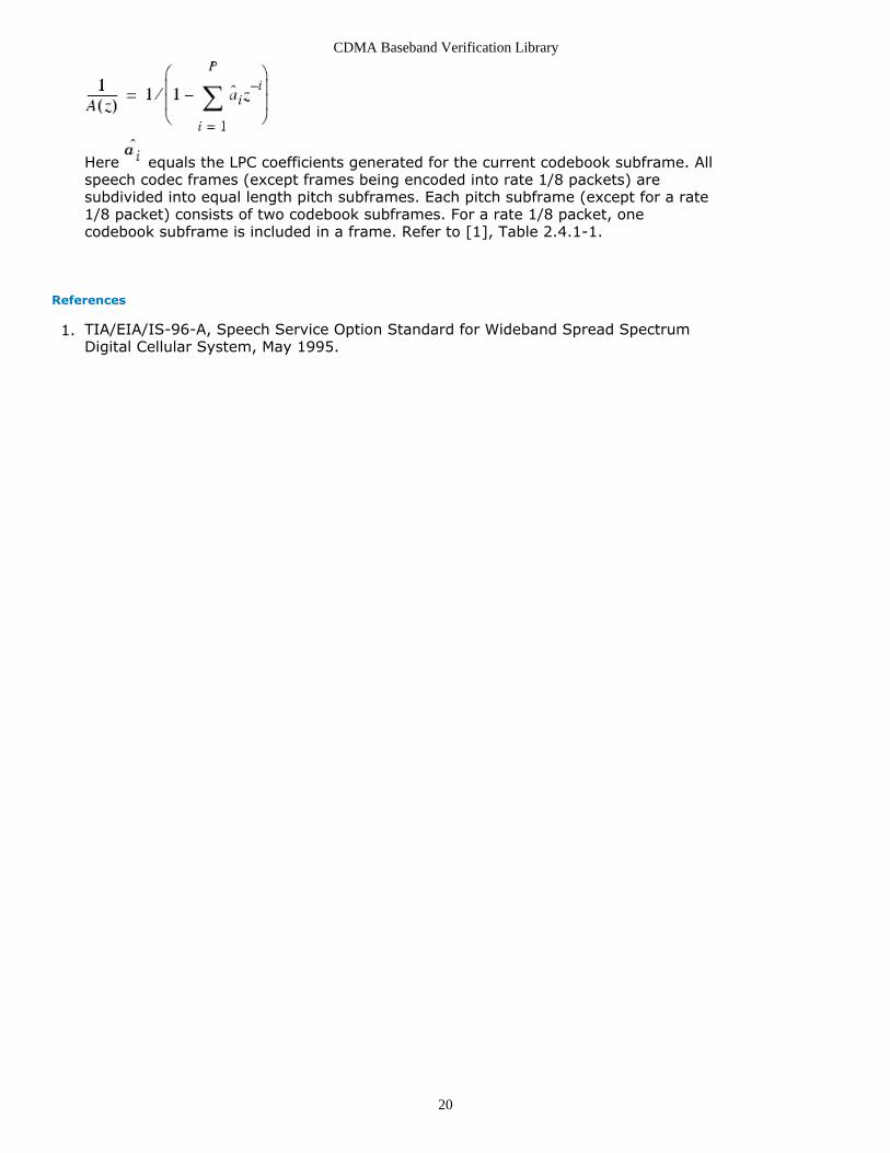
This component filters the input signal through an LPC filter. The default of LPC filter1.order is 10; the default frame length is 160.Each firing, FSize lpcOut tokens are produced when (MAX_PITCH_SF×LpcOrder)lpcCof, FSize pitchI and 1 rate tokens are consumed. The MAX_PITCH_SF constant isdefined in celpStdValue.h, the MAX_PITCH_SF default is 4.Implementation.2.The filter is designed using transfer function
CDMA Baseband Verification Library
20
Here equals the LPC coefficients generated for the current codebook subframe. Allspeech codec frames (except frames being encoded into rate 1/8 packets) aresubdivided into equal length pitch subframes. Each pitch subframe (except for a rate1/8 packet) consists of two codebook subframes. For a rate 1/8 packet, onecodebook subframe is included in a frame. Refer to [1], Table 2.4.1-1.
References
TIA/EIA/IS-96-A, Speech Service Option Standard for Wideband Spread Spectrum1.Digital Cellular System, May 1995.

CDMA Baseband Verification Library
21
CDMA_GainPostFilter PartCategories: CELP Codecs (cdmabasever)
The models associated with this part are listed below. To view detailed information on amodel (description, parameters, equations, notes, etc.), please click the appropriate link.
Model Description
CDMA_GainPostFilter (cdmabasever) Post filter to Enhance Quality of Reconstructed Speech Signal.
CDMA_GainPostFilter
Description: Post filter to Enhance Quality of Reconstructed Speech Signal.Domain: UntimedC++ Code Generation Support: NOAssociated Parts: CDMA GainPostFilter Part (cdmabasever)
Model Parameters
Name Description Default Units Type RuntimeTunable
Range Symbol
PF_Control post filter control indicator:1=on, 0=off
1 Integer NO {0,1}
FSize length of frame 160 Integer NO (0:∞)
LpcOrder order of LPC filter 10 Integer NO (0:∞) P
PF_ZeroWghtFactor weighting factor of post zerofilter
0.5 Float NO (0.0:1.0] p
PF_PoleWghtFactor weighting factor of post polefilter
0.8 Float NO (0.0:1.0] s
AGC_Factor interpolation factor of postgain
0.9375 Float NO (0.0:1.0)
AGC_Num number of subframes whencomputing post gain
4 Integer NO (0:∞)
FirstFrameDiscardFlag flag to indicate use of firstframe: 1=discard, 0=process
1 Integer NO {0,1}
Input Ports
Port Name Description Signal Type Optional
1 inLsp Interpolated LSP values. real NO
2 lpcCof LPC coefficients. real NO
3 lpcIn The signal output from LPC filter. real NO
4 rate Data rate of the current frame. int NO
Output Ports
Port Name Description Signal Type Optional
5 sigOut The output signal of this model. real NO
Notes/Equations

CDMA Baseband Verification Library
22
This component generates the output of adaptive postfilter PF(z), pf(n). A gain1.control is placed on the output of PF(z) to generate the reconstructed speech signal sd
(n); this ensures that the energy of the output signal is close to the energy of theinput signal. (Refer to reference [1], paragraph 2.4.8.5.)The LPC filter order default is 10; the length of frame default is 160.Each firing, FSize sigOut tokens are produced when (MAX_PITCH_SF×LpcOrder)lpcCof, (MAX_PITCH_SF×LpcOrder) inLsp, FSize lpcIn and 1 rate tokens areconsumed. The MAX_PITCH_SF constant is defined in celpStdValue.h; the defaultnumber of MAX_PITCH_SF is 4.Implementation2.yd (n) is filtered by postfilter PF(z) to produce pf(n). PF(z) has the form:
whereA(z) is the formant prediction error filter defined in the formant synthesis filter,the coefficients of A(z) are equal to the LPC coefficients appropriate for thecurrent codebook subframe.B(z) is an anti-tilt filter designed to offset the spectral tilt as follows (γ is afunction of the average of the interpolated LSP frequencies):B(z) = (1 − γz-1 ) / (1 + γz-1 )
References
TIA/EIA/IS-96-A, Speech Service Option Standard for Wideband Spread Spectrum1.Digital Cellular System, May 1995.

CDMA Baseband Verification Library
23
CDMA_HammingWindow PartCategories: CELP Codecs (cdmabasever)
The models associated with this part are listed below. To view detailed information on amodel (description, parameters, equations, notes, etc.), please click the appropriate link.
Model Description
CDMA_HammingWindow (cdmabasever) The Hamming Window for the InputSignal
CDMA_HammingWindow
Description: The Hamming Window for the Input SignalDomain: UntimedC++ Code Generation Support: NOAssociated Parts: CDMA HammingWindow Part (cdmabasever)
Model Parameters
Name Description Default Units Type Runtime Tunable Range
MultipleCoeff coefficient used to amplify theoutput
1.0 Float NO (0:∞)
FSize length of signal frame 160 Integer NO (0:∞)
Input Ports
Port Name Description Signal Type Optional
1 sigDC The signal with DC removed real NO
Output Ports
Port Name Description Signal Type Optional
2 sigHam The signal after HammingWindow
real NO
Notes/Equations
This component windows the dc-removed input samples with a Hamming window.1.(See reference [1] paragraph 2.4.3.2.2.)Each firing, FSize sigHam tokens are produced when FSize sigDC tokens areconsumed. The default length of FSize is 160.Implementation2.
sw (n) = MultipleCoeff× s(n) ×(0.54 − 0.46 cos (2 π n / (FSize − 1)))
where
n = 1, 2, ... , FSize

CDMA Baseband Verification Library
24
References
TIA/EIA/IS-96-A, Speech Service Option Standard for Wideband Spread Spectrum1.Digital Cellular System, May 1995.

CDMA Baseband Verification Library
25
CDMA_LPC_ToLSP PartCategories: CELP Codecs (cdmabasever)
The models associated with this part are listed below. To view detailed information on amodel (description, parameters, equations, notes, etc.), please click the appropriate link.
Model Description
CDMA_LPC_ToLSP (cdmabasever) LPC coefficients to LSP Frequencies Converter.
CDMA_LPC_ToLSP
Description: LPC coefficients to LSP Frequencies Converter.Domain: UntimedC++ Code Generation Support: NOAssociated Parts: CDMA LPC ToLSP Part (cdmabasever)
Model Parameters
Name Description Default Units Type RuntimeTunable
Range Symbol
LoopNumber number of root searches in rootscope [0,0.5]
800 Integer NO (0:∞)
LpcOrder order of LPC filter 10 Integer NO (0:∞) LP
IterateNumber number of iterations for convergingto the root
100 Integer NO (0:∞)
Input Ports
Port Name Description Signal Type Optional
1 lpcCof Input LPC coefficients. real NO
Output Ports
Port Name Description Signal Type Optional
2 lspFrq Output LSP frequencies notinterpolated.
real NO
Notes/Equations
This component converts LPC coefficients in the time domain to LSP frequencies in1.the frequency domain for ease of quantization. (See reference [1], paragraph2.4.3.2.6.)Each firing, LP lspFrq tokens are produced when LP lpcCof are consumed. TheLpcOrder default is 10.Implementation2.LSP frequencies are roots of the following equations.

CDMA Baseband Verification Library
26
Search the roots of these equations; LSP frequencies can then be found.
References
TIA/EIA/IS-96-A, Speech Service Option Standard for Wideband Spread Spectrum1.Digital Cellular System, May 1995.

CDMA Baseband Verification Library
27
CDMA_LSP_ToLPC PartCategories: CELP Codecs (cdmabasever)
The models associated with this part are listed below. To view detailed information on amodel (description, parameters, equations, notes, etc.), please click the appropriate link.
Model Description
CDMA_LSP_ToLPC (cdmabasever) LSP Frequencies to LPC Coefficients Converter.
CDMA_LSP_ToLPC
Description: LSP Frequencies to LPC Coefficients Converter.Domain: UntimedC++ Code Generation Support: NOAssociated Parts: CDMA LSP ToLPC Part (cdmabasever)
Model Parameters
Name Description Default Units Type RuntimeTunable
Range Symbol
LSP_Increase minimum LSPfrequency spacing
0.01 Float NO (0:∞) &apdelta;w<sup>
</sup>min{~}
LpcOrder order of LPC filter 10 Integer NO (0:∞) P
FirstFrameDiscardFlag flag to indicate use offirst frame:1=discard,0=process
1 Integer NO {0,1}
Input Ports
Port Name Description Signal Type Optional
1 lspFrq LSP converted back from code. real NO
2 rate Data rate of current frame. int NO
Output Ports
Port Name Description Signal Type Optional
3 lpcCof LPC converted back from LSP. real NO
4 inLsp Interpolated LSP according to subframe. real NO
Notes/Equations
In this component, LSP frequencies are interpolated; the interpolated LSP frequencies1.are then converted back to LPC coefficients for use in pitch and codebook parametersearching. The LpcOrder default is 10.Each firing, (MAX_PITCH_SF×LpcOrder) lpcCof and (MAX_PITCH_SF×LpcOrder) inLsptokens are produced when LpcOrder lspFrq and 1 rate tokens are consumed. Here,the MAX_PITCH_SF constant is defined in celpStdValue.h; the MAX_PITCH_SF defaultis 4.

CDMA Baseband Verification Library
28
References
TIA/EIA/IS-96-A, Speech Service Option Standard for Wideband Spread Spectrum1.Digital Cellular System, May 1995.

CDMA Baseband Verification Library
29
CDMA_PitchCdbkSelector PartCategories: CELP Codecs (cdmabasever)
The models associated with this part are listed below. To view detailed information on amodel (description, parameters, equations, notes, etc.), please click the appropriate link.
Model Description
CDMA_PitchCdbkSelector (cdmabasever) Optimal Pitch and Codebook Parameters Selector.
CDMA_PitchCdbkSelector
Description: Optimal Pitch and Codebook Parameters Selector.Domain: UntimedC++ Code Generation Support: NOAssociated Parts: CDMA PitchCdbkSelector Part (cdmabasever)
Model Parameters
Name Description Default Units Type RuntimeTunable
Range Symbol
MinGain minimum pitch gain 0.0 Float NO [0:∞)
MaxGain maximum pitch gain 2.0 Float NO [0:∞)
StepGain step of pitch gain whensearching
0.25 Float NO (0:∞)
MinLag minimum pitch lag 17 Integer NO [0:∞)
MaxLag maximum pitch lag 143 Integer NO [0:∞)
StepLag step of pitch lag whensearching
1 Integer NO (0:∞)
MinIndex minimum codebook index 0 Integer NO [0:∞)
MaxIndex maximum codebook index 127 Integer NO [0:∞)
StepIndex step of codebook index whensearching
1 Integer NO (0:∞)
MperceptWghtFactor weighting factor of perceptualweighted filter
0.8 Float NO (0:1.0] z
FSize length of frame 160 Integer NO [0:∞)
LpcOrder order of LPC filter 10 Integer NO (0:∞) P
FirstFrameDiscardFlag flag to indicate use of firstframe: 1=discard, 0=process
1 Integer NO {0,1}
Input Ports
Port Name Description Signal Type Optional
1 sigIn The speech signal with dc removed. real NO
2 pLpcCo LPC corresponding to pitchsubframe.
real NO
3 rate Data rate of current frame. int NO
4 lspCd LSP transmission code for Rate 1/8. int NO
Output Ports

CDMA Baseband Verification Library
30
Port Name Description Signal Type Optional
5 pitchB transmission code of pitch gain. int NO
6 pitchL transmission code of pitch lag. int NO
7 cdbkI transmission code of codebook index orseed.
int NO
8 cdbkG transmission code of codebook gain. int NO
Notes/Equations
This component selects the optimal pitch lag L* and gain b*, codebook gain G* and1.index I* and quantifies these parameters to transmission codes. The LpcOrder defaultis 10; the FSize default is 160.Each firing, MAX_PITCH_SF pitchB, MAX_PITCH_SF pitchL, 2×MAX_PITCH_SF cdbkI,2×MAX_PITCH_SF cdbkG tokens are produced when FSize sigIn, 1 rate and LpcOrderpLpcCo, LpcOrder lspCd tokens are consumed. Here MAX_PITCH_SF is constantdefined in celpStdValue.h; the MAX_PITCH_SF default is 4.Implementation2.Analysis-by-synthesis is used to select pitch parameters, where encoding is done byselecting parameters that minimize the weighted error between the input and thesynthesized speech. See the following figure.
Analysis-by-Synthesis for Pitch Parameter Search
A similar method is used to select codebook vector and gain. See the following figure.The selected codebook index and the codebook gain are allowable values thatminimize the weighted error between the synthesized speech and the input speech.(See reference [1].)

CDMA Baseband Verification Library
31
Analysis-by-Synthesis for Codebook Parameter Search
References
TIA/EIA/IS-96-A, Speech Service Option Standard for Wideband Spread Spectrum1.Digital Cellular System, May 1995.

CDMA Baseband Verification Library
32
CDMA_PitchFilter PartCategories: CELP Codecs (cdmabasever)
The models associated with this part are listed below. To view detailed information on amodel (description, parameters, equations, notes, etc.), please click the appropriate link.
Model Description
CDMA_PitchFilter (cdmabasever) The Pitch Filter to Reconstruct Speech Signal.
CDMA_PitchFilter
Description: The Pitch Filter to Reconstruct Speech Signal.Domain: UntimedC++ Code Generation Support: NOAssociated Parts: CDMA PitchFilter Part (cdmabasever)
Model Parameters
Name Description Default Units Type RuntimeTunable
Range
FSize length of frame 160 Integer NO (0:∞)
MinLag minimum pitch lag 17 Integer NO (0:∞)
MaxLag maximum pitch lag 143 Integer NO (0:∞)
MinGain minimum pitch gain 0.0 Float NO [0:∞)
FirstFrameDiscardFlag flag to indicate use of first frame:1=discard, 0=process
1 Integer NO {0,1}
Input Ports
Port Name Description Signal Type Optional
1 pitchL Pitch lag. int NO
2 pitchB Pitch gain. int NO
3 sCdbkV The vector generated by the scaleCdbkGeneratormodel.
real NO
4 rate Data rate of the current frame. int NO
Output Ports
Port Name Description Signal Type Optional
5 pitchO The output of thismodel.
real NO
Notes/Equations
This component generates the pitch synthesis filter signal. Filter 1/P(z) uses optimal1.pitch gain b and pitch lag L converted back from the transmission code PLAGi andPGAINi that are appropriate for the current pitch subframe. The FSize default is 160.Each firing, FSize pitchO tokens are produced when MAX_PITCH_SF pitchB,MAX_PITCH_SF pitchL, FSize sCdbkV, 1 rate tokens are consumed. HereMAX_PITCH_SF is constant defined in celpStdValue.h and the default number of

CDMA Baseband Verification Library
33
MAX_PITCH_SF is 4.
References
TIA/EIA/IS-96-A, Speech Service Option Standard for Wideband Spread Spectrum1.Digital Cellular System, May 1995.

CDMA Baseband Verification Library
34
CDMA_QuantizerWi PartCategories: CELP Codecs (cdmabasever)
The models associated with this part are listed below. To view detailed information on amodel (description, parameters, equations, notes, etc.), please click the appropriate link.
Model Description
CDMA_QuantizerWi (cdmabasever) LSP frequencies to Transmission Code Quantizer.
CDMA_QuantizerWi
Description: LSP frequencies to Transmission Code Quantizer.Domain: UntimedC++ Code Generation Support: NOAssociated Parts: CDMA QuantizerWi Part (cdmabasever)
Model Parameters
Name Description Default Units Type RuntimeTunable
Range Symbol
LpcOrder order of LPC filter 10 Integer NO (0:∞) P
FirstFrameDiscardFlag flag to indicate use of firstframe: 1=discard, 0=process
1 Integer NO {0,1}
Input Ports
Port Name Description Signal Type Optional
1 lspFrq LSP frequecies. real NO
2 rate Data rate of this frame. int NO
Output Ports
Port Name Description Signal Type Optional
3 lspCd The output of the quantizer. int NO
Notes/Equations
This component converts LSP frequencies to transmission code; a predictor and1.quantizer are included; see the following figure. The quantizer is a linear quantizerthat varies in dynamic range and step size for different rates.The LpcOrder default is 10.Each firing, P lspCd tokens are produced when P lspFrq and 1 rate tokens areconsumed.

CDMA Baseband Verification Library
35
Converting LSP Frequencies to Transmission Codes
References
TIA/EIA/IS-96-A, Speech Service Option Standard for Wideband Spread Spectrum1.Digital Cellular System, May 1995.

CDMA Baseband Verification Library
36
CDMA_ReadSigFile PartCategories: CELP Codecs (cdmabasever)
The models associated with this part are listed below. To view detailed information on amodel (description, parameters, equations, notes, etc.), please click the appropriate link.
Model Description
CDMA_ReadSigFile (cdmabasever) Read Waveform File for Signal generation
CDMA_ReadSigFile
Description: Read Waveform File for Signal generationDomain: UntimedC++ Code Generation Support: NOAssociated Parts: CDMA ReadSigFile Part (cdmabasever)
Model Parameters
Name Description Default Units Type RuntimeTunable
FileName name of file to be read file.wav Filename NO
OutputType type of simulation: periodic or non_periodic:periodic, non_periodic
periodic Enumeration NO
Output Ports
Port Name Description Signal Type Optional
1 sigOut Output signal. int NO
Notes/Equations
CDMA_ReadSigFile is a test component to read speech signals from a Microsoft WAV1.file. The simulation can be stopped at end of file, or the file contents can beperiodically repeated. 8 kHz sample rate, 16 bits per sample and mono channel filetypes are supported.Each firing, 1 sigOut token is produced.

CDMA Baseband Verification Library
37
CDMA_RemoveDC PartCategories: CELP Codecs (cdmabasever)
The models associated with this part are listed below. To view detailed information on amodel (description, parameters, equations, notes, etc.), please click the appropriate link.
Model Description
CDMA_RemoveDC (cdmabasever) Remove DC from InputSignal.
CDMA_RemoveDC
Description: Remove DC from Input Signal.Domain: UntimedC++ Code Generation Support: NOAssociated Parts: CDMA RemoveDC Part (cdmabasever)
Model Parameters
Name Description Default Units Type RuntimeTunable
Range
LowPassRatio lowpass ratio to interpolate filter theaverage
0.75 Float NO [0:1]
FSize length of signal frame 160 Integer NO (0:∞)
Input Ports
Port Name Description Signal Type Optional
1 sigIn The original speech signal real NO
Output Ports
Port Name Description Signal Type Optional
2 sigDC The signal with dcremoved
real NO
Notes/Equations
This component removes the dc offset from the input samples. The FSize default is1.160.Each firing, FSize sigDC tokens are produced when FSize sigIn tokens are consumed.

CDMA Baseband Verification Library
38
CDMA_ScaledCdbkVector PartCategories: CELP Codecs (cdmabasever)
The models associated with this part are listed below. To view detailed information on amodel (description, parameters, equations, notes, etc.), please click the appropriate link.
Model Description
CDMA_ScaledCdbkVector (cdmabasever) Scaled Codebook Vector Generator.
CDMA_ScaledCdbkVector
Description: Scaled Codebook Vector Generator.Domain: UntimedC++ Code Generation Support: NOAssociated Parts: CDMA ScaledCdbkVector Part (cdmabasever)
Model Parameters
Name Description Default Units Type RuntimeTunable
Range
FSize length of frame 160 Integer NO (0:∞)
FirstFrameDiscardFlag flag to indicate use of first frame:1=discard, 0=process
1 Integer NO {0,1}
Input Ports
Port Name Description Signal Type Optional
1 cdbkI codebook index. int NO
2 cdbkG codebook gain. int NO
3 rate Data rate the current frame. int NO
Output Ports
Port Name Description Signal Type Optional
4 sCdbkV Vector generated by this model. real NO
Notes/Equations
This component generates the scaled codebook vector according to optimal codebook1.index and gain for rate (except 1/8), and seed for rate 1/8. The default length offrame is 160. Each firing, FSize sCdbkV tokens are produced when 2×MAX_PITCH_SFcdbkI, 2×MAX_PITCH_SF cdbkG, 1 rate tokens are consumed. Here MAX_PITCH_SFis constant defined in celpStdValue.h and the default number of MAX_PITCH_SF is 4.
References
TIA/EIA/IS-96-A, Speech Service Option Standard for Wideband Spread Spectrum1.Digital Cellular System, May 1995.

CDMA Baseband Verification Library
39
CDMA_UnquantizerWi PartCategories: CELP Codecs (cdmabasever)
The models associated with this part are listed below. To view detailed information on amodel (description, parameters, equations, notes, etc.), please click the appropriate link.
Model Description
CDMA_UnquantizerWi (cdmabasever) Transmission Code to LSP FrequenciesUnquantizer.
CDMA_UnquantizerWi
Description: Transmission Code to LSP Frequencies Unquantizer.Domain: UntimedC++ Code Generation Support: NOAssociated Parts: CDMA UnquantizerWi Part (cdmabasever)
Model Parameters
Name Description Default Units Type RuntimeTunable
Range Symbol
LpcOrder order of LPC filter 10 Integer NO (0:∞) P
FirstFrameDiscardFlag flag to indicate use of firstframe: 1=discard, 0=process
1 Integer NO {0,1}
Input Ports
Port Name Description Signal Type Optional
1 lspCd LSP transimission code. int NO
2 rate Data rate of current frame . int NO
Output Ports
Port Name Description Signal Type Optional
3 lspFrq LSP frequencies. real NO
Notes/Equations
This component converts LSP transmission codes back to LSP frequencies (this is the1.reverse function of CDMA_QuantizerWi). LpcOrder default is 10.Each firing, P lspFrq tokens are produced when P lspCd and 1 rate tokens areconsumed.
References
TIA/EIA/IS-96-A, Speech Service Option Standard for Wideband Spread Spectrum1.Digital Cellular System, May 1995.

CDMA Baseband Verification Library
40
CDMA_VariableDataRate PartCategories: CELP Codecs (cdmabasever)
The models associated with this part are listed below. To view detailed information on amodel (description, parameters, equations, notes, etc.), please click the appropriate link.
Model Description
CDMA_VariableDataRate (cdmabasever) Data Rate Selector Based on SpeechActivity.
CDMA_VariableDataRate
Description: Data Rate Selector Based on Speech Activity.Domain: UntimedC++ Code Generation Support: NOAssociated Parts: CDMA VariableDataRate Part (cdmabasever)
Model Parameters
Name Description Default Units Type RuntimeTunable
Range
RateMode rate mode indicator: 0=variable rate;1=fixed rate 1; 2=fixed rate1/2
0 Integer NO {0,1,2}
BackNoiseThreshold background noise threshold 160000 Integer NO (0:∞)
BaseNoiseThreshold basic noise threshold 5059644 Integer NO (0:∞)
ThresholdMultiple multiple coefficient 1.00547 Float NO (0:∞)
FirstFrameDiscardFlag flag to indicate use of first frame:1=discard, 0=process
1 Integer NO {0,1}
Input Ports
Port Name Description Signal Type Optional
1 auFir The first value of autofun. real NO
3 blkCtl Here 0 is not blank frame, 1 is blankframe.
int NO
Output Ports
Port Name Description Signal Type Optional
2 rate The rate of the currentframe.
int NO
Notes/Equations
This component makes an initial rate selection based on the energy in the frame and1.a set of three thresholds (see reference [1] 2.4.4). Refer to the following table forpacket and data rates. Upon command, the speech codec will generate a blankpacket. Each firing, 1 rate token is produced when 1 auFir and 1 blkCtl tokens areconsumed.

CDMA Baseband Verification Library
41
rate Packet Type Bits per Packet
0 Rate 1 171
1 Rate 1/2 80
2 Rate 1/4 40
3 Rate 1/8 16
4 Blank 0
5 Rate 1 with bit errors 171
6 Insufficient frame quality (erasure) 0
References
TIA/EIA/IS-96-A, Speech Service Option Standard for Wideband Spread Spectrum1.Digital Cellular System, May 1995.

CDMA Baseband Verification Library
42
CDMA_WriteSigFile PartCategories: CELP Codecs (cdmabasever)
The models associated with this part are listed below. To view detailed information on amodel (description, parameters, equations, notes, etc.), please click the appropriate link.
Model Description
CDMA_WriteSigFile (cdmabasever) Write Reconstructed Signal to a Data File
CDMA_WriteSigFile
Description: Write Reconstructed Signal to a Data FileDomain: UntimedC++ Code Generation Support: NOAssociated Parts: CDMA WriteSigFile Part (cdmabasever)
Model Parameters
Name Description Default Units Type Runtime Tunable
WriteFileName output filename
output.wav Filename NO
Input Ports
Port Name Description Signal Type Optional
1 SigOut The reconstructed speech signal. real NO
Output Ports
Port Name Description Signal Type Optional
2 output output the values written into file1-> real NO
Notes/Equations
CDMA_WriteSigFile is a test component to write speech signals into a Microsoft WAV1.file with an 8 kHz sample rate, 16 bits per sample and a mono channel. The firstframe of the input signal is jumped due to initialization, other signals will be writteninto the file specified by WriteFileName. A default frame length of 160 is used. Eachfiring, 1 sigOut input token is consumed and 1 output token is produced.

CDMA Baseband Verification Library
43
CDMA Channel Codecs Category Contents
CDMA AccessDeintlvr Part (cdmabasever)CDMA AccessIntlvr Part (cdmabasever)CDMA AddTail Part (cdmabasever)CDMA BitCC Part (cdmabasever)CDMA CC WithTail Part (cdmabasever)CDMA DCC WithTail Part (cdmabasever)CDMA EraseTail Part (cdmabasever)CDMA ErrorRate Part (cdmabasever)CDMA FwdChCoder Part (cdmabasever)CDMA FwdChDecoder Part (cdmabasever)CDMA FwdViterbiDCC Part (cdmabasever)CDMA LogicToNRZ Part (cdmabasever)CDMA OneBitQuantizer Part (cdmabasever)CDMA OneWayVD Part (cdmabasever)CDMA PgFwdTrfDeintlvr Part (cdmabasever)CDMA PgFwdTrfIntlvr Part (cdmabasever)CDMA Repeat Part (cdmabasever)CDMA RevChCoder Part (cdmabasever)CDMA RevChDecoder Part (cdmabasever)CDMA RevOneway Part (cdmabasever)CDMA RevTrfDeintlvr Part (cdmabasever)CDMA RevTrfIntlvr Part (cdmabasever)CDMA SyncDeintlvr Part (cdmabasever)CDMA SyncIntlvr Part (cdmabasever)CDMA TrffcFrmGen Part (cdmabasever)CDMA TrffcFrmRcvry Part (cdmabasever)CDMA VariableRateCC Part (cdmabasever)CDMA VariableRateDCC Part (cdmabasever)CDMA ViterbiBitDCC Part (cdmabasever)

CDMA Baseband Verification Library
44
CDMA_AccessDeintlvr PartCategories: Channel Codecs (cdmabasever)
The models associated with this part are listed below. To view detailed information on amodel (description, parameters, equations, notes, etc.), please click the appropriate link.
Model Description
CDMA_AccessDeintlvr(cdmabasever)
Access Channel Deinterleaver. This module de-interleaves the code symbolfor CDMA Access Channel.
CDMA_AccessDeintlvr
Description: Access Channel Deinterleaver. This module de-interleaves the code symbolfor CDMA Access Channel.Domain: UntimedC++ Code Generation Support: NOAssociated Parts: CDMA AccessDeintlvr Part (cdmabasever)
Input Ports
Port Name Description Signal Type Optional
1 input the input symbol to be interleaved. real NO
Output Ports
Port Name Description Signal Type Optional
2 output the interleaved symbol. real NO
Notes/Equations
This component is used to deinterleave the input coded symbol for the CDMA access1.channel. 576 output tokens are produced when 576 input tokens are consumed.Implementation2.Deinterleaving is the reverse function of interleaving. The symbol is written into thedeinterleaver by row; the row number is bit-reversed and read by the deinterleaverby column. The bit-reversal function rearranges the input array, of which length N isa power of 2. The index (decimal) is converted into a binary number. For a 32-length
array:
can be denoted as binary number , with a range of 0 to 31;
is a 5-bit binary number, , where , , , ,
.
is the bit reversal index of . This function rearranges the input array by exchanging
the number of index for the number of bit reversal index .
References

CDMA Baseband Verification Library
45
TIA/EIA/IS-95-A, Mobile Station-Base Station Compatibility Standard for Dual-Mode1.Wideband Spread Spectrum Cellular System, May 1995.
CDMA Baseband Verification Library
46
CDMA_AccessIntlvr PartCategories: Channel Codecs (cdmabasever)
The models associated with this part are listed below. To view detailed information on amodel (description, parameters, equations, notes, etc.), please click the appropriate link.
Model Description
CDMA_AccessIntlvr(cdmabasever)
Access Channel Interleaver. This module interleaves the coded symbol forCDMA Access Channel.
CDMA_AccessIntlvr
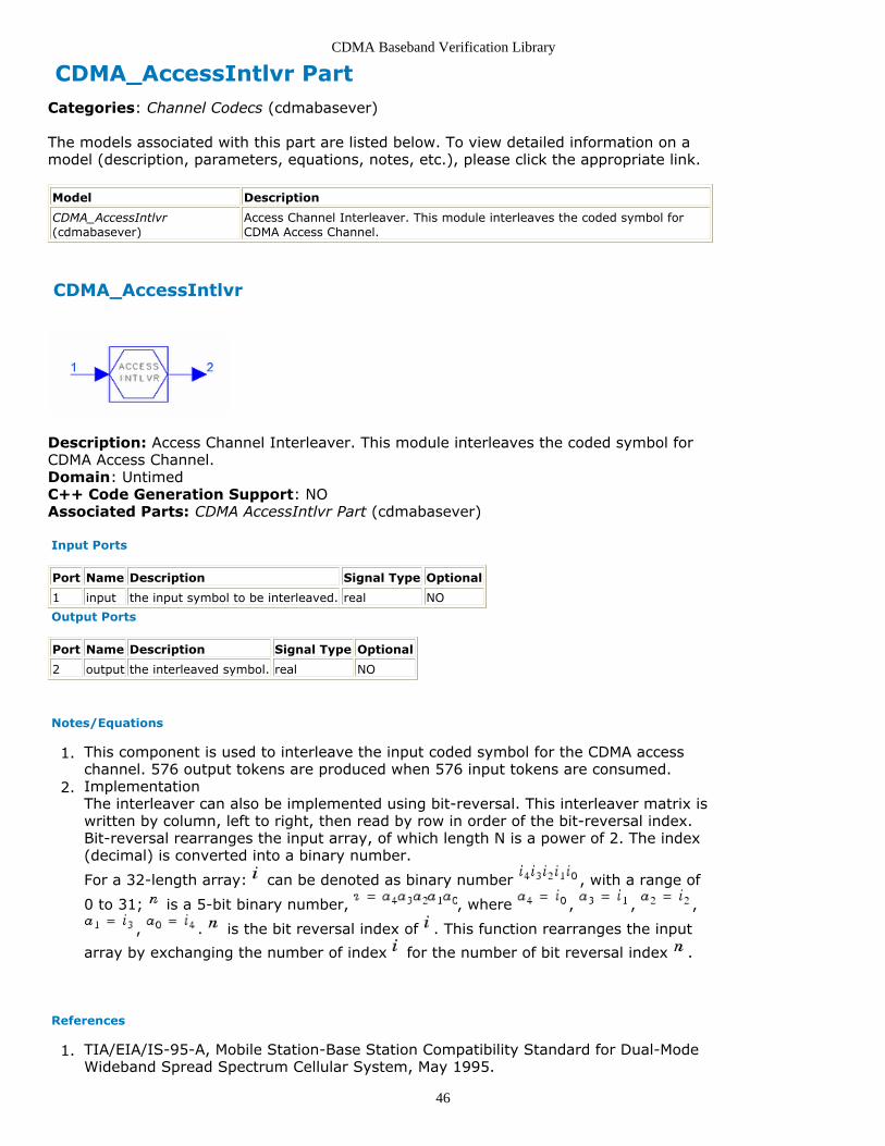
Description: Access Channel Interleaver. This module interleaves the coded symbol forCDMA Access Channel.Domain: UntimedC++ Code Generation Support: NOAssociated Parts: CDMA AccessIntlvr Part (cdmabasever)
Input Ports
Port Name Description Signal Type Optional
1 input the input symbol to be interleaved. real NO
Output Ports
Port Name Description Signal Type Optional
2 output the interleaved symbol. real NO
Notes/Equations
This component is used to interleave the input coded symbol for the CDMA access1.channel. 576 output tokens are produced when 576 input tokens are consumed.Implementation2.The interleaver can also be implemented using bit-reversal. This interleaver matrix iswritten by column, left to right, then read by row in order of the bit-reversal index.Bit-reversal rearranges the input array, of which length N is a power of 2. The index(decimal) is converted into a binary number.
For a 32-length array: can be denoted as binary number , with a range of
0 to 31; is a 5-bit binary number, , where , , ,
, . is the bit reversal index of . This function rearranges the input
array by exchanging the number of index for the number of bit reversal index .
References
TIA/EIA/IS-95-A, Mobile Station-Base Station Compatibility Standard for Dual-Mode1.Wideband Spread Spectrum Cellular System, May 1995.

CDMA Baseband Verification Library
47
CDMA_AddTail PartCategories: Channel Codecs (cdmabasever)
The models associated with this part are listed below. To view detailed information on amodel (description, parameters, equations, notes, etc.), please click the appropriate link.
Model Description
CDMA_AddTail(cdmabasever)
Tail bits adder. This model adds tail bits for the frame that needs tail bits foremploying convolutional code.
CDMA_AddTail
Description: Tail bits adder. This model adds tail bits for the frame that needs tail bits foremploying convolutional code.Domain: UntimedC++ Code Generation Support: NOAssociated Parts: CDMA AddTail Part (cdmabasever)
Model Parameters
Name Description Default Units Type Runtime Tunable Range
FrameLength input framelength
88 Integer NO (0:∞)
TailLength tail bits length 8 Integer NO [0:∞)
Input Ports
Port Name Description Signal Type Optional
1 input The information bits. int NO
Output Ports
Port Name Description Signal Type Optional
2 output The data of frame withtail.
int NO
Notes/Equations
This component is used to add tail bits for the frame that needs tail bits for1.convolutional coding.FrameLength+TailLength output tokens are produced when FrameLength inputtokens are consumed. For example, in a CDMA access channel, Framelength=88, andTailLength=8; 96 output tokens are produced when 88 input tokens are consumed.

CDMA Baseband Verification Library
48
CDMA_BitCC PartCategories: Channel Codecs (cdmabasever)
The models associated with this part are listed below. To view detailed information on amodel (description, parameters, equations, notes, etc.), please click the appropriate link.
Model Description
CDMA_BitCC (cdmabasever) Bit-By-Bit ConvolutionalEncoder
CDMA_BitCC
Description: Bit-By-Bit Convolutional EncoderDomain: UntimedC++ Code Generation Support: NOAssociated Parts: CDMA BitCC Part (cdmabasever)
Model Parameters
Name Description Default Units Type RuntimeTunable
Range
CCType convolutional code type: rate 1/2 K 9 g0 0753 g10561, rate 1/3 K 9 g0 0557 g1 0663 g2 0711, rate1/2 K 7 g0 0554 g1 0744, rate 1/3 K 7 g0 0554g1 0624 g2 0764, rate 1/2 K 5 g0 046 g1 072,rate 1/3 K 5 g0 066 g1 052 g2 076, rate 1/2 K 5g0 046 g1 066, rate 1/6 K 5 g0 066 g1 052 g2076 g3 066 g4 052 g5 076, rate 1/2 K 3 g0 05 g107
rate 1/2 K9 g0 0753g1 0561
Enumeration NO †
Input Ports
Port Name Description Signal Type Optional
1 input the bits to be convolutionally encoded. int NO
Output Ports
Port Name Description Signal Type Optional
2 output Convolutionally encodedsymbols.
int NO
Notes/Equations
This component is used to convolutionally encode the input bit.1.1/rate (specified by CCType) output tokens are produced when one input token isconsumed.For example, in CDMA Sync channel, CC(2,1,9) is used in which the convolutionalcode rate is 1/2. CCType is set to rate 1/2 K 9 g0 0753 g1 0561 and two outputtokens are produced when one input token is consumed.

CDMA Baseband Verification Library
49
References
S. Lin and D. J. Costello, Jr., Error Control Coding Fundamentals and Applications,1.Prentice Hall, Englewood Cliffs NJ, 1983.

CDMA Baseband Verification Library
50
CDMA_CC_WithTail PartCategories: Channel Codecs (cdmabasever)
The models associated with this part are listed below. To view detailed information on amodel (description, parameters, equations, notes, etc.), please click the appropriate link.
Model Description
CDMA_CC_WithTail(cdmabasever)
Convolutional Encoder with tail. This model convolutionally encodes the inputtailed frame.
CDMA_CC_WithTail
Description: Convolutional Encoder with tail. This model convolutionally encodes theinput tailed frame.Domain: UntimedC++ Code Generation Support: NOAssociated Parts: CDMA CC WithTail Part (cdmabasever)
Model Parameters
Name Description Default Units Type RuntimeTunable
Range
CCType convolutional code type: rate 1/2 K 9 g00753 g1 0561, rate 1/3 K 9 g0 0557 g10663 g2 0711, rate 1/2 K 7 g0 0554 g10744, rate 1/3 K 7 g0 0554 g1 0624 g20764, rate 1/2 K 5 g0 046 g1 072, rate 1/3K 5 g0 066 g1 052 g2 076, rate 1/2 K 5 g0046 g1 066, rate 1/6 K 5 g0 066 g1 052 g2076 g3 066 g4 052 g5 076, rate 1/2 K 3 g005 g1 07
rate 1/2 K9 g0 0753g1 0561
Enumeration NO †
InputFrameLen input frame length 96 Integer NO [K:∞)
Input Ports
Port Name Description Signal Type Optional
1 input The data to be convolutionallyencoded
int NO
Output Ports
Port Name Description Signal Type Optional
2 output Convolutionally encodedsymbols
int NO
Notes/Equations
This component is used to convolutionally encode the input tailed frame.1.InputFrameLen/rate (specified by CCType) output tokens are produced whenInputFrameLen input tokens are consumed.For example, in the CDMA access channel, CC(3,1,9) is used where the convolutionalcode rate is 1/3 and the frame length is 96. CCType is set to rate 1/3 K 9 g0 0557 g1

CDMA Baseband Verification Library
51
0663 g2 0711 and InputFrameLen is 96. 288 output tokens are produced when 96input tokens are consumed.
References
S. Lin and D. J. Costello, Jr., Error Control Coding Fundamentals and Applications ,1.Prentice Hall, Englewood Cliffs NJ, 1983.

CDMA Baseband Verification Library
52
CDMA_DCC_WithTail PartCategories: Channel Codecs (cdmabasever)
The models associated with this part are listed below. To view detailed information on amodel (description, parameters, equations, notes, etc.), please click the appropriate link.
Model Description
CDMA_DCC_WithTail(cdmabasever)
Viterbi Decoder for Convolutional Code with Tail. This module does viterbidecoding for truncated convolutional code.
CDMA_DCC_WithTail
Description: Viterbi Decoder for Convolutional Code with Tail. This module does viterbidecoding for truncated convolutional code.Domain: UntimedC++ Code Generation Support: NOAssociated Parts: CDMA DCC WithTail Part (cdmabasever)
Model Parameters
Name Description Default Units Type RuntimeTunable
Range
CCType convolutional code type: rate 1/2 K 9 g00753 g1 0561, rate 1/3 K 9 g0 0557 g10663 g2 0711, rate 1/2 K 7 g0 0554 g10744, rate 1/3 K 7 g0 0554 g1 0624 g20764, rate 1/2 K 5 g0 046 g1 072, rate 1/3K 5 g0 066 g1 052 g2 076, rate 1/2 K 5 g0046 g1 066, rate 1/6 K 5 g0 066 g1 052 g2076 g3 066 g4 052 g5 076, rate 1/2 K 3 g005 g1 07
rate 1/2 K9 g0 0753g1 0561
Enumeration NO †
InputFrameLen input frame length 288 Integer NO [K:∞)
Input Ports
Port Name Description Signal Type Optional
1 input the symbols to bedecoded.
real NO
Output Ports
Port Name Description Signal Type Optional
2 output the decodedbits.
int NO
Notes/Equations
This component is used to Viterbi-decode convolutional code with tail.1.InputFrameLen×rate (specified by CCType) output tokens are produced whenInputFrameLen input tokens are consumed.For example, in CDMA access channel, CC(3,1,9) is used in which the convolutionalcode rate is 1/3 and the frame length is 288. CCType is set to rate 1/3 K 9 g0 0557

CDMA Baseband Verification Library
53
g1 0663 g2 0711 and InputFrameLen is 288. 96 output tokens are produced when288 input tokens are consumed.Implementation2.Viterbi Decoding AlgorithmThe following is the Viterbi algorithm for decoding a CC(n,k,K) code, where K is theconstraint length of convolutional code. In our components, the convolutional code isprocessed with k=1.Branch Metric Calculation
The branch metric , at the J th instant of the path through the trellis isdefined as the logarithm of the joint probability of the received n-bit symbol
conditioned on the estimated transmitted n-bit symbol
for the path. That is,If Rake receiver is regarded as a part of the channel, for the Viterbi decoder thechannel can be considered as an AWGN channel. Therefore,
Path Metric Calculation
The path metric for the path at the J th instant is the sum of the branchmetrics belonging to the path from the first instant to the J th instant. Therefore,
Information Sequence Update
There are merging paths at each node in the trellis and the decoder selects from
the paths , the one having the largest metric, namely,
and this path is known as the survivor.Decoder OutputWhen the two survivors have been determined at the J th instant, the decoderoutputs the ( J-L )th information symbol from its memory of the survivor with thelargest metric.
References
S. Lin and D. J. Costello, Jr., Error Control Coding Fundamentals and Applications,1.Prentice Hall, Englewood Cliffs NJ, 1983.R. Steele (Editor), Mobile Radio Communication, IEEE Press, June 1995.2.

CDMA Baseband Verification Library
54
CDMA_EraseTail PartCategories: Channel Codecs (cdmabasever)
The models associated with this part are listed below. To view detailed information on amodel (description, parameters, equations, notes, etc.), please click the appropriate link.
Model Description
CDMA_EraseTail(cdmabasever)
Tail bits eraser. This module deletes the tail bits added in the transmittingend.
CDMA_EraseTail
Description: Tail bits eraser. This module deletes the tail bits added in the transmittingend.Domain: UntimedC++ Code Generation Support: NOAssociated Parts: CDMA EraseTail Part (cdmabasever)
Model Parameters
Name Description Default Units Type Runtime Tunable Range
TailLength tail length 8 Integer NO (0:∞)
InputFrameLen input framelength
96 Integer NO (TailLength:∞)
Input Ports
Port Name Description Signal Type Optional
1 input The input block. int NO
Output Ports
Port Name Description Signal Type Optional
2 output The output block. int NO
Notes/Equations
This component is used to erase the tail bits added in the transmitting end.1.InputFrameLen−TailLength output tokens are produced when InputFrameLen inputtokens are consumed. For example, in CDMA access channel, 88 output tokens areproduced when 96 input tokens are consumed.

CDMA Baseband Verification Library
55
CDMA_ErrorRate PartCategories: Channel Codecs (cdmabasever)
The models associated with this part are listed below. To view detailed information on amodel (description, parameters, equations, notes, etc.), please click the appropriate link.
Model Description
CDMA_ErrorRate(cdmabasever)
Error Rate Estimation. This model compares the two input blocks to estimatethe BER.
CDMA_ErrorRate
Description: Error Rate Estimation. This model compares the two input blocks toestimate the BER.Domain: UntimedC++ Code Generation Support: NOAssociated Parts: CDMA ErrorRate Part (cdmabasever)
Model Parameters
Name Description Default Units Type Runtime Tunable Range
TestLength test length 192 Integer NO (0:∞)
Input Ports
Port Name Description Signal Type Optional
1 in1 The first channel signal. int NO
2 in2 The second channel signal. int NO
Output Ports
Port Name Description Signal Type Optional
3 output The error rate in this block. real NO
Notes/Equations
This component is used to compare the two input blocks and estimate the error rate1.in this block.One output token is produced for each set of TestLength input tokens consumed.

CDMA Baseband Verification Library
56
CDMA_FwdChCoder Part CDMA Forward Traffic Channel Encoder
Categories: Channel Codecs (cdmabasever)
The models associated with this part are listed below. To view detailed information on amodel (description, parameters, equations, notes, etc.), please click the appropriate link.
Model
CDMA_FwdChCoder (cdmabasever)
CDMA_FwdChCoder
Description: CDMA Forward Traffic Channel EncoderAssociated Parts: CDMA FwdChCoder Part (cdmabasever)
Input Ports
Port Name Description Signal Type Optional
1 in1 Terminal: Standard Data PortTerminal
int NO
2 in2 Terminal: Standard Data PortTerminal
int NO
Output Ports
Port Name Description Signal Type Optional
3 output Terminal: Standard Data PortTerminal
real NO
Notes/Equations
This subnetwork is used to implement forward traffic channel encoding. It is a1.combination of frame generator, Viterbi encoder, mapping bits to NRZ, andinterleaver.Implementation2.Refer to the following figure. The CDMA_FwdChCoder subnetwork includesCDMA_TrffcFrmGen, CDMA_VariableRateCC, CDMA_Repeat, CDMA_LogicToNRZ, andCDMA_PgFwdIntlvr.

CDMA Baseband Verification Library
57
Forward Traffic Channel Encoder
References
TIA/EIA/IS-95-A, Mobile Station-Base Station Compatibility Standard for Dual-Mode1.Wideband Spread Spectrum Cellular System, May 1995.

CDMA Baseband Verification Library
58
CDMA_FwdChDecoder Part CDMA Forward Traffic Channel Deoder
Categories: Channel Codecs (cdmabasever)
The models associated with this part are listed below. To view detailed information on amodel (description, parameters, equations, notes, etc.), please click the appropriate link.
Model
CDMA_FwdChDecoder (cdmabasever)
CDMA_FwdChDecoder
Description: CDMA Forward Traffic Channel DeoderAssociated Parts: CDMA FwdChDecoder Part (cdmabasever)
Input Ports
Port Name Description Signal Type Optional
1 input Terminal: Standard Data PortTerminal
real NO
Output Ports
Port Name Description Signal Type Optional
2 output Terminal: Standard Data PortTerminal
int NO
3 rate0 Terminal: Standard Data PortTerminal
int NO
Notes/Equations
This subnetwork is used to implement forward traffic channel decoding. It is a1.combination of Viterbi decoder, rate detector and frame recovery.Implementation2.Refer to the following figure. The CDMA_FwdChDecoder subnetwork includesCDMA_PgFwdDeintlvr, CDMA_FwdViterbiDCC, and CDMA_TrffcFrmRcvry.Input data from CDMA_FwdRake is soft decision values for the Viterbi decoder.CDMA_PgFwdIntlvr deinterleaves the input data. CDMA_FwdViterbiDCC completes therate detection and Viterbi decoding. CDMA_TrffcFrmRcvry recovers the frame that issame as the source.
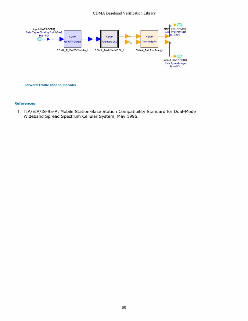
CDMA Baseband Verification Library
59
Forward Traffic Channel Decoder
References
TIA/EIA/IS-95-A, Mobile Station-Base Station Compatibility Standard for Dual-Mode1.Wideband Spread Spectrum Cellular System, May 1995.

CDMA Baseband Verification Library
60
CDMA_FwdViterbiDCC Part CDMA Forward Traffic Channel 4-way Viterbi Decoder
Categories: Channel Codecs (cdmabasever)
The models associated with this part are listed below. To view detailed information on amodel (description, parameters, equations, notes, etc.), please click the appropriate link.
Model
CDMA_FwdViterbiDCC (cdmabasever)
CDMA_FwdViterbiDCC
Description: CDMA Forward Traffic Channel 4-way Viterbi DecoderAssociated Parts: CDMA FwdViterbiDCC Part (cdmabasever)
Input Ports
Port Name Description Signal Type Optional
1 input Terminal: Standard Data PortTerminal
real NO
Output Ports
Port Name Description Signal Type Optional
2 output Terminal: Standard Data PortTerminal
int NO
3 rateO Terminal: Standard Data PortTerminal
int NO
Notes/Equations
This subnetwork is used to implement forward traffic channel Viterbi decoding.1.Implementation2.Refer to the following figure. The CDMA_FwdViterbiDCC subnetwork includesCDMA_OneWayVD and CDMA_Select1in4.Input data from CDMA_FwdRake and CDMA_PgFwdDeintlvr is soft decision values forViterbi decoding.In CDMA_OneWayVD, decoding is performed according to data rates. After decoding,data is encoded again using the same generator function; results are compared withthe data before decoding, and the bit error rate is calculated. The date rate withminimum BER is used as the transmit data rate.

CDMA Baseband Verification Library
61
Forward Traffic Channel Viterbi Decoder
References
TIA/EIA/IS-95-A, Mobile Station-Base Station Compatibility Standard for Dual-Mode1.Wideband Spread Spectrum Cellular System, May 1995.

CDMA Baseband Verification Library
62
CDMA_LogicToNRZ PartCategories: Channel Codecs (cdmabasever)
The models associated with this part are listed below. To view detailed information on amodel (description, parameters, equations, notes, etc.), please click the appropriate link.
Model Description
CDMA_LogicToNRZ(cdmabasever)
Logic-to-NRZ Converter for CDMA systems. This model maps the logic datainto the NRZ Binary Signaling.
CDMA_LogicToNRZ
Description: Logic-to-NRZ Converter for CDMA systems. This model maps the logic datainto the NRZ Binary Signaling.Domain: UntimedC++ Code Generation Support: NOAssociated Parts: CDMA LogicToNRZ Part (cdmabasever)
Model Parameters
Name Description Default Units Type RuntimeTunable
Range
Amplitude amplitude of NRZ binary signaling 1.0 Float NO (-∞:-1e-6) (1e-6:∞)
ChannelType channel type:CDMA Forward TrafficChannel, CDMA Reverse Traffic Channel,Others: CDMA Forward Traffic Channel,CDMA Reverse Traffic Channel, Others
Others Enumeration NO
Input Ports
Port Name Description SignalType
Optional
1 input The input logic data. int NO
2 rateI Only used in Forward Traffic Channel. If not used, please connectconstant 0.
int NO
Output Ports
Port Name Description Signal Type Optional
3 output The output NRZ Binary Signaling data. real NO
4 rateO data rate . int NO
Notes/Equations
This component is used to map logic data into NRZ binary signaling and adjust1.symbol amplitude by data rate.For CDMA Forward Traffic Channel, 384 output tokens are produced when 384 inputtokens are consumed; for CDMA Reverse Traffic Channel, 576 input tokens areproduced when 576 input tokens are consumed; for Others, one output token is

CDMA Baseband Verification Library
63
produced when one input token is consumed (rateI is not useful for Others, it can beconnected to any bits).Implementation2.For CDMA Forward Traffic Channel, all repeated symbols will be transmitted. Theamplitude of logic-to-real mapping is inversely proportional to the data rate. Theinput and output block structure for CDMA Forward Traffic Channel or CDMA ReverseTraffic Channel is shown in the following table.
Variable Rate Frame Block Structure
Data Rate Block Length Block Structure
Valid DataInteger/Block PaddingInteger/Block
full rate (9600 bps) MaxFrameLen MaxFrameLen 0
half rate (4800 bps) MaxFrameLen MaxFrameLen/2 MaxFrameLen/2
1/4 rate (2400 bps) MaxFrameLen MaxFrameLen/4 3×MaxFrameLen/4
1/8 rate (1200 bps) MaxFrameLen MaxFrameLen/8 7×MaxFrameLen/8
References
TIA/EIA/IS-95-A, Mobile Station-Base Station Compatibility Standard for Dual-Mode1.Wideband Spread Spectrum Cellular System, May 1995.

CDMA Baseband Verification Library
64
CDMA_OneBitQuantizer PartCategories: Channel Codecs (cdmabasever)
The models associated with this part are listed below. To view detailed information on amodel (description, parameters, equations, notes, etc.), please click the appropriate link.
Model Description
CDMA_OneBitQuantizer (cdmabasever) One-Bit Quantizer. This module maps the input real data into logic.
CDMA_OneBitQuantizer
Description: One-Bit Quantizer. This module maps the input real data into logic.Domain: UntimedC++ Code Generation Support: NOAssociated Parts: CDMA OneBitQuantizer Part (cdmabasever)
Input Ports
Port Name Description Signal Type Optional
1 input the input data. real NO
Output Ports
Port Name Description Signal Type Optional
2 output the output data. int NO
Notes/Equations
This component is used to map real data into logic. If data > 0, output data is 0; else1.output data is 1.One output token is produced when one input token is consumed.

CDMA Baseband Verification Library
65
CDMA_OneWayVD Part CDMA Forward One Rate Decoder
Categories: Channel Codecs (cdmabasever)
The models associated with this part are listed below. To view detailed information on amodel (description, parameters, equations, notes, etc.), please click the appropriate link.
Model
CDMA_OneWayVD (cdmabasever)
CDMA_OneWayVD
Description: CDMA Forward One Rate DecoderAssociated Parts: CDMA OneWayVD Part (cdmabasever)
Model Parameters
Name Description Default Units Type RuntimeTunable
Times number of times to repeat input data ({1,2,4,8) 1 none Integer NO
datarate transmit data rate frame: 0=full, 1=1/2, 2=1/4, 3=1/8({0,1,2,3)
0 none Integer NO
Input Ports
Port Name Description Signal Type Optional
1 input Terminal: Standard Data PortTerminal
real NO
Output Ports
Port Name Description Signal Type Optional
2 Err Terminal: Standard Data PortTerminal
real NO
3 output Terminal: Standard Data PortTerminal
int NO
4 rate0 Terminal: Standard Data PortTerminal
int NO
Notes/Equations
This subnetwork is used to implement channel decoding of a data rate. It is a1.combination of deinterleaving, Viterbi decoder, encoder and BER calculator.Implementation:2.Refer to the following figure. The CDMA_OneWayVD subnetwork includesCDMA_OneBitQuantizer, CDMA_DCC_WithTail, CDMA_CC_WithTail, CDMA_Erasetail,CDMA_ErrorRate and CDMA_AddTail.Input data is soft decision values with a certain rate for Viterbi decoder.Deinterleaving and decoding are performed according to the data rate. After decodingdata is encoded again with the same code; results are compared with the data before

CDMA Baseband Verification Library
66
decoding, and the bit error rate is calculated.
Forward One Rate Channel Decoder
References
TIA/EIA/IS-95-A, Mobile Station-Base Station Compatibility Standard for Dual-Mode1.Wideband Spread Spectrum Cellular System, May 1995.

CDMA Baseband Verification Library
67
CDMA_PgFwdTrfDeintlvr PartCategories: Channel Codecs (cdmabasever)
The models associated with this part are listed below. To view detailed information on amodel (description, parameters, equations, notes, etc.), please click the appropriate link.
Model Description
CDMA_PgFwdTrfDeintlvr(cdmabasever)
Paging Channel and Forward Traffic Channel Deinterleaver. This module de-interleaves the code symbol for CDMA Paging and Forward Traffic Channel.
CDMA_PgFwdTrfDeintlvr
Description: Paging Channel and Forward Traffic Channel Deinterleaver. This module de-interleaves the code symbol for CDMA Paging and Forward Traffic Channel.Domain: UntimedC++ Code Generation Support: NOAssociated Parts: CDMA PgFwdTrfDeintlvr Part (cdmabasever)
Input Ports
Port Name Description Signal Type Optional
1 input the input symbol to be interleaved. real NO
Output Ports
Port Name Description Signal Type Optional
2 output the interleaved symbol. real NO
Notes/Equations
This component is used to deinterleave the input coded symbol for CDMA Paging1.Channel and Forward Traffic Channel.384 output tokens are produced when 384 input tokens are consumed.Implementation2.Deinterleaving is the reverse function of interleaving (described inCDMA_PgFwdTrfIntlvr). This channel deinterleaver is also a 64×6 matrix. The symbolis written into the deinterleaver by row; row numbers are bit-reversed and read bythe deinterleaver by column.Bit-reversal rearranges the input array, of which length N is a power of 2. The index(decimal) is converted into a binary number. For example, for a 32-length array, the
index of the number of this array can be denoted as binary number cdma-3-16-
061.gif!, with a range of 0 to 31, and is a 5-bit binary number, ,
where , , , , .
Then the number is the bit-reversal index of index . This function rearranges the
input array by exchanging the number of index for the number of bit reversal index .
CDMA Baseband Verification Library
68
References
TIA/EIA/IS-95-A, Mobile Station-Base Station Compatibility Standard for Dual-Mode1.Wideband Spread Spectrum Cellular System, May 1995.

CDMA Baseband Verification Library
69
CDMA_PgFwdTrfIntlvr PartCategories: Channel Codecs (cdmabasever)
The models associated with this part are listed below. To view detailed information on amodel (description, parameters, equations, notes, etc.), please click the appropriate link.
Model Description
CDMA_PgFwdTrfIntlvr(cdmabasever)
Paging Channel and Forward Traffic Channel Interleaver. This moduleinterleaves the coded symbol for CDMA Paging and Forward Traffic Channel.
CDMA_PgFwdTrfIntlvr
Description: Paging Channel and Forward Traffic Channel Interleaver. This moduleinterleaves the coded symbol for CDMA Paging and Forward Traffic Channel.Domain: UntimedC++ Code Generation Support: NOAssociated Parts: CDMA PgFwdTrfIntlvr Part (cdmabasever)
Input Ports
Port Name Description Signal Type Optional
1 input the input symbol to be interleaved. real NO
Output Ports
Port Name Description Signal Type Optional
2 output the interleaved symbol. real NO
Notes/Equations
This component is used to interleave the input coded symbol for CDMA Paging1.Channel and Forward Traffic Channel.384 output tokens are produced when 384 input tokens are consumed.Implementation2.This interleaver can also be implemented using bit-reversal.A 64×6 matrix is formed and is written by column, left to the right. The matrix isread by row in the order of bit reversal index.Bit-reversal rearranges the input array, of which length N is a power of 2. The index
(decimal) is converted into binary numbers. For a 32-length array, can be denoted
as binary number , with a range of 0 to 31, and is a 5-bit binary number,
, where , , , , . is the bit reversalindex of . This function rearranges the input array by exchanging the number ofindex for the number of bit reversal index .
References
TIA/EIA/IS-95-A, Mobile Station-Base Station Compatibility Standard for Dual-Mode1.

CDMA Baseband Verification Library
70
Wideband Spread Spectrum Cellular System, May 1995.

CDMA Baseband Verification Library
71
CDMA_Repeat PartCategories: Channel Codecs (cdmabasever)
The models associated with this part are listed below. To view detailed information on amodel (description, parameters, equations, notes, etc.), please click the appropriate link.
Model Description
CDMA_Repeat(cdmabasever)
Repeater for CDMA systems. This model repeats the variable rate frame data to getthe same symbol rate in CDMA system.
CDMA_Repeat
Description: Repeater for CDMA systems. This model repeats the variable rate framedata to get the same symbol rate in CDMA system.Domain: UntimedC++ Code Generation Support: NOAssociated Parts: CDMA Repeat Part (cdmabasever)
Model Parameters
Name Description Default Units Type RuntimeTunable
Channel channel type:Forward Traffic Channel ,ReverseTraffic Channel: Forward Traffic Channel, ReverseTraffic Channel
ForwardTrafficChannel
Enumeration NO
Input Ports
Port Name Description Signal Type Optional
1 input the input stream. real NO
2 rateI the data rate offrame.
int NO
Output Ports
Port Name Description Signal Type Optional
3 output the repeated symbol. real NO
4 rateO the data rate offrame.
int NO
Notes/Equations
This component repeats the variable data rate frame to get the same symbol rate in1.CDMA systems.For Forward Traffic Channel, 384 output tokens are produced when 384 input tokensare consumed. For Reverse Traffic Channel, 576 output tokens are produced when576 input tokens are consumed.Implementation2.The input block structure is given in the following table. For Reverse Traffic ChannelMaxFrameLen is 576; for Forward Traffic Channel MaxFrameLen is 384. The ReverseTraffic Channel output block structure includes 576 symbols; the Forward Traffic

CDMA Baseband Verification Library
72
Channel output block structure includes 384 symbols.
Input Block Structure
Data Rate Block Length Block Structure
Valid Data Integer/Block Padding Integer/Block
full rate (9600 bps) MaxFrameLen MaxFrameLen 0
half rate (4800 bps) MaxFrameLen MaxFrameLen/2 MaxFrameLen/2
1/4 rate (2400 bps) MaxFrameLen MaxFrameLen/4 3×MaxFrameLen/4
1/8 rate (1200 bps) MaxFrameLen MaxFrameLen/8 7×MaxFrameLen/8
References
TIA/EIA/IS-95-A, Mobile Station-Base Station Compatibility Standard for Dual-Mode1.Wideband Spread Spectrum Cellular System, May 1995.

CDMA Baseband Verification Library
73
CDMA_RevChCoder Part CDMA Reverse Traffic Channel Encoder
Categories: Channel Codecs (cdmabasever)
The models associated with this part are listed below. To view detailed information on amodel (description, parameters, equations, notes, etc.), please click the appropriate link.
Model
CDMA_RevChCoder (cdmabasever)
CDMA_RevChCoder
Description: CDMA Reverse Traffic Channel EncoderAssociated Parts: CDMA RevChCoder Part (cdmabasever)
Model Parameters
Name Description Default Units Type Runtime Tunable
preamble preamble frame number([0:inf))
0 none Integer NO
Input Ports
Port Name Description Signal Type Optional
1 Port_1 Terminal: Standard Data PortTerminal
int NO
2 Port_2 Terminal: Standard Data PortTerminal
int NO
Output Ports
Port Name Description Signal Type Optional
3 Port_3 Terminal: Standard Data PortTerminal
real NO
4 Port_4 Terminal: Standard Data PortTerminal
int NO
Notes/Equations
This subnetwork is used to implement reverse traffic channel encoder. It is a1.combination of frame generator, Viterbi encoder, mapping bits to NRZ, andinterleaver.Implementation2.Refer to the following figure. The CDMA_RevChCoder subnetwork includesCDMA_TrffcFrmGen, CDMA_VariableRateCC, CDMA_Repeat, CDMA_LogicToNRZ, andCDMA_RevTrfIntlvr.

CDMA Baseband Verification Library
74
Reverse Traffic Channel Encoder
References
TIA/EIA/IS-95-A, Mobile Station-Base Station Compatibility Standard for Dual-Mode1.Wideband Spread Spectrum Cellular System, May 1995.

CDMA Baseband Verification Library
75
CDMA_RevChDecoder Part CDMA Reverse Traffic Channel Decoder
Categories: Channel Codecs (cdmabasever)
The models associated with this part are listed below. To view detailed information on amodel (description, parameters, equations, notes, etc.), please click the appropriate link.
Model
CDMA_RevChDecoder (cdmabasever)
CDMA_RevChDecoder
Description: CDMA Reverse Traffic Channel DecoderAssociated Parts: CDMA RevChDecoder Part (cdmabasever)
Input Ports
Port Name Description Signal Type Optional
1 input Terminal: Standard Data PortTerminal
real NO
2 LgCode Terminal: Standard Data PortTerminal
int NO
Output Ports
Port Name Description Signal Type Optional
3 output Terminal: Standard Data PortTerminal
int NO
4 rate0 Terminal: Standard Data PortTerminal
int NO
Notes/Equations
This subnetwork is used to implement channel decoding. It is a combination of Viterbi1.decoder, rate detector and frame recovery.Implementation2.Refer to the following figure. The CDMA_RevChDecoder subnetwork includesCDMA_BSRateconverter, CDMA_RevOneway, CDMA_Select1In4,CDMA_TrffcFrmRcvry.Input data is soft decision values for Viterbi decoding. CDMA_BSRateconverterrecovers the transmitted frame according to the data burst randomizing algorithm.The recovered frame is output to CDMA_RevOneway where deinterleaving anddecoding are performed according to the data rate; decoded data is encoded againwith the same code; results are compared with the data before decoding and the BERis calculated. The data rate with the minimum BER is the transmit data rate.CDMA_TrffcFrmRcvry recovers the frame that is the same as the source.

CDMA Baseband Verification Library
76
Reverse Channel Decoder
References
TIA/EIA/IS-95-A, Mobile Station-Base Station Compatibility Standard for Dual-Mode1.Wideband Spread Spectrum Cellular System, May 1995.
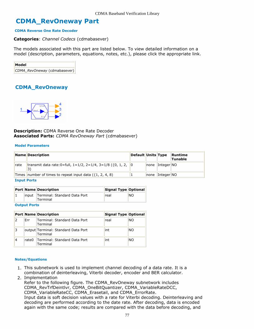
CDMA Baseband Verification Library
77
CDMA_RevOneway Part CDMA Reverse One Rate Decoder
Categories: Channel Codecs (cdmabasever)
The models associated with this part are listed below. To view detailed information on amodel (description, parameters, equations, notes, etc.), please click the appropriate link.
Model
CDMA_RevOneway (cdmabasever)
CDMA_RevOneway
Description: CDMA Reverse One Rate DecoderAssociated Parts: CDMA RevOneway Part (cdmabasever)
Model Parameters
Name Description Default Units Type RuntimeTunable
rate transmit data rate:0=full, 1=1/2, 2=1/4, 3=1/8 ({0, 1, 2,3)
0 none Integer NO
Times number of times to repeat input data ({1, 2, 4, 8) 1 none Integer NO
Input Ports
Port Name Description Signal Type Optional
1 input Terminal: Standard Data PortTerminal
real NO
Output Ports
Port Name Description Signal Type Optional
2 Err Terminal: Standard Data PortTerminal
real NO
3 output Terminal: Standard Data PortTerminal
int NO
4 rate0 Terminal: Standard Data PortTerminal
int NO
Notes/Equations
This subnetwork is used to implement channel decoding of a data rate. It is a1.combination of deinterleaving, Viterbi decoder, encoder and BER calculator.Implementation2.Refer to the following figure. The CDMA_RevOneway subnetwork includesCDMA_RevTrfDeintlvr, CDMA_OneBitQuantizer, CDMA_VariableRateDCC,CDMA_VariableRateCC, CDMA_Erasetail, and CDMA_ErrorRate.Input data is soft decision values with a rate for Viterbi decoding. Deinterleaving anddecoding are performed according to the date rate. After decoding, data is encodedagain with the same code; results are compared with the data before decoding, and

CDMA Baseband Verification Library
78
the BER is calculated.
One Rate Reverse Channel Decoder
References
TIA/EIA/IS-95-A, Mobile Station-Base Station Compatibility Standard for Dual-Mode1.Wideband Spread Spectrum Cellular System, May 1995.

CDMA Baseband Verification Library
79
CDMA_RevTrfDeintlvr PartCategories: Channel Codecs (cdmabasever)
The models associated with this part are listed below. To view detailed information on amodel (description, parameters, equations, notes, etc.), please click the appropriate link.
Model Description
CDMA_RevTrfDeintlvr(cdmabasever)
Reverse Traffic Channel Deinterleaver. This module deinterleaves theinput symbol forReverse Traffic Channel
CDMA_RevTrfDeintlvr
Description Reverse Traffic Channel Deinterleaver. This module deinterleaves the inputsymbol forLibrary CDMA, Channel CodecsClass SDFCDMA_RevTrfDeintlvr
Pin Inputs
Pin Name Description Signal Type
1 input The input code symbol. real
2 rateI The input code symbol rate. int
Pin Outputs
Pin Name Description Signal Type
3 output The output code symbol. real
4 rateO The output code symbolrate.
int
Notes/Equations
This component is used to deinterleave the input coded symbol for CDMA Reverse1.Traffic Channel.576 output tokens are produced when 576 input tokens are consumed.Implementation2.Since the rate-decision of Reverse Traffic Channel is done in Rake Receiver, the inputblock of Reverse Traffic Channel deinterleaver is a variable data rate frame. Since thevalid data is changed according to the data rate, the deinterleaver is also changedaccording to the data rate. The number of columns is a constant 18 according to theReverse Traffic Channel interleaver; the row number is the current frame lengthdivided by the column number. The input and output block structures are the sameand are given in the following table. The algorithm of this deinterleaver is to writeinto the deinterleaver by row and read by column.
Input and Output Block Structure

CDMA Baseband Verification Library
80
Data Rate Block Length Structure
Valid Data Integer/Block Padding Integer/Block
full rate (9600 bps) 576 576 0
half rate (4800 bps) 576 288 288
1/4 rate (2400 bps) 576 144 432
1/8 rate (1200 bps) 576 72 504
References
TIA/EIA/IS-95-A, Mobile Station-Base Station Compatibility Standard for Dual-Mode1.Wideband Spread Spectrum Cellular System, May 1995.

CDMA Baseband Verification Library
81
CDMA_RevTrfIntlvr PartCategories: Channel Codecs (cdmabasever)
The models associated with this part are listed below. To view detailed information on amodel (description, parameters, equations, notes, etc.), please click the appropriate link.
Model Description
CDMA_RevTrfIntlvr(cdmabasever)
Reverse Traffic Channel Interleaver. This module interleaves the input codesymbol forReverse Traffic Channel.
CDMA_RevTrfIntlvr
Description: Reverse Traffic Channel Interleaver. This module interleaves the input codesymbol forReverse Traffic Channel.Domain: UntimedC++ Code Generation Support: NOAssociated Parts: CDMA RevTrfIntlvr Part (cdmabasever)
Input Ports
Port Name Description Signal Type Optional
1 input the input code symbols to be interleaved real NO
2 rateI the data rate of frame int NO
Output Ports
Port Name Description Signal Type Optional
3 output the interleaved code symbols. real NO
4 rateO the data rate of frame int NO
Notes/Equations
This component is used to interleave the input coded symbol for CDMA Reverse1.Traffic Channel. 576 output tokens are produced when 576 input tokens areconsumed.Implementation2.The Reverse Traffic Channel symbol is interleaved in a unit of power control group;the burst randomizer algorithm is used to discard the repeated power control group.A power control group includes the symbols in two rows of the interleaver. Since thealgorithm is concerned with the repetition times, data rate information is transmittedin rateI.
References
TIA/EIA/IS-95-A, Mobile Station-Base Station Compatibility Standard for Dual-Mode1.Wideband Spread Spectrum Cellular System, May 1995.

CDMA Baseband Verification Library
82
CDMA_SyncDeintlvr PartCategories: Channel Codecs (cdmabasever)
The models associated with this part are listed below. To view detailed information on amodel (description, parameters, equations, notes, etc.), please click the appropriate link.
Model Description
CDMA_SyncDeintlvr(cdmabasever)
Sync Channel Deinterleaver. This module deinterleaves the input code symbolfor CDMA Sync Channel.
CDMA_SyncDeintlvr
Description: Sync Channel Deinterleaver. This module deinterleaves the input codesymbol for CDMA Sync Channel.Domain: UntimedC++ Code Generation Support: NOAssociated Parts: CDMA SyncDeintlvr Part (cdmabasever)
Input Ports
Port Name Description Signal Type Optional
1 input The input data to be de-interleaved.
real NO
Output Ports
Port Name Description Signal Type Optional
2 output The output interleaved symbol. real NO
Notes/Equations
This component is used to deinterleave the input coded symbol for CDMA Sync1.Channel.128 output tokens are produced when 128 input tokens are consumed.Implementation2.Deinterleaving is the reverse function of interleaving (described in CDMA_SyncIntlvr).The bit reversal function rearranges the input array, of which length N is a power of2. The index (decimal) is converted into a binary number. For a 32-length array, the
index of the number of this array can be denoted as a binary number ,
with a range of 0 to 31, and is a 5-bit binary
number, , where , , , , .
The number is the bit reversal index of index . This function rearranges the input
array by exchanging the number of index
for the number of bit reversal index .

CDMA Baseband Verification Library
83
References
TIA/EIA/IS-95-A, Mobile Station-Base Station Compatibility Standard for Dual-Mode1.Wideband Spread Spectrum Cellular System, May 1995.

CDMA Baseband Verification Library
84
CDMA_SyncIntlvr PartCategories: Channel Codecs (cdmabasever)
The models associated with this part are listed below. To view detailed information on amodel (description, parameters, equations, notes, etc.), please click the appropriate link.
Model Description
CDMA_SyncIntlvr(cdmabasever)
Sync Channel Interleaver. This module interleaves the input coded symbol forCDMA Sync Channel.
CDMA_SyncIntlvr
Description: Sync Channel Interleaver. This module interleaves the input coded symbolfor CDMA Sync Channel.Domain: UntimedC++ Code Generation Support: NOAssociated Parts: CDMA SyncIntlvr Part (cdmabasever)
Input Ports
Port Name Description Signal Type Optional
1 input The input code symbol tointerleaved.
real NO
Output Ports
Port Name Description Signal Type Optional
2 output The output interleaved symbol. real NO
Notes/Equations
This component is used to interleave the input coded symbol for CDMA Sync Channel.1.128 output tokens are produced when 128 input tokens are consumed.Implementation2.Sync Channel symbols are interleaved by a bit-reversal technique.Bit-reversal rearranges the input array, of which length N is a power of 2. The index(decimal) is converted into a binary number. For example, for a 32-length array, the
index of the number of this array can be denoted as binary number , witha range of 0 to 31, and is a 5-bit binary
number , where , , , , .Then the number is the bit reversal index of index . This function rearranges theinput array by exchanging the number of index for the number of bit reversal index
.
References
TIA/EIA/IS-95-A, Mobile Station-Base Station Compatibility Standard for Dual-Mode1.

CDMA Baseband Verification Library
85
Wideband Spread Spectrum Cellular System, May 1995.

CDMA Baseband Verification Library
86
CDMA_TrffcFrmGen PartCategories: Channel Codecs (cdmabasever)
The models associated with this part are listed below. To view detailed information on amodel (description, parameters, equations, notes, etc.), please click the appropriate link.
Model Description
CDMA_TrffcFrmGen(cdmabasever)
CDMA Traffic Channel Frame Generator. This module generates the frame ofTraffic Channel.
CDMA_TrffcFrmGen
Description: CDMA Traffic Channel Frame Generator. This module generates the frame ofTraffic Channel.Domain: UntimedC++ Code Generation Support: NOAssociated Parts: CDMA TrffcFrmGen Part (cdmabasever)
Model Parameters
Name Description Default Units Type RuntimeTunable
Range
PreambleNumber preamble frame number in CDMAReverse Traffic Channel
0 Integer NO [0:∞)
Type type of channel:CDMA Forward TrafficChannel, CDMA Reverse TrafficChannel: CDMA Forward TrafficChannel, CDMA Reverse TrafficChannel
CDMAForwardTrafficChannel
Enumeration NO
Input Ports
Port Name Description Signal Type Optional
1 input The input stream int NO
2 rateI The data rate of CDMA Traffic Channelframe.
int NO
Output Ports
Port Name Description Signal Type Optional
3 output The output stream. int NO
4 rateO The data rate of CDMA Traffic Channelframe.
int NO
Notes/Equations
This component is used to generate the traffic channel frame.1.In CDMA systems, 192 output and 1 rateO tokens are produced when 171 input and1 rateI tokens are consumed.Implementation2.

CDMA Baseband Verification Library
87
Data Rate Index Packet Type Bits per Packet
0 Rate 1 171
1 Rate 1/2 80
2 Rate 1/4 40
3 Rate 1/8 16
4 Reserved Reserved
5 Rate 1 with errors 171
6 Insufficient frame quality(erasure) 0
IS-95A Traffic Channel Frame Structure
Data Rate FrameLength
Frame Structure
Reserved(Bit/Frame)
Information(Bit/Frame)
CRC(Bit/Frame)
Tail(Bit/Frame)
full rate(9600 bps)
192 1 (value=0) 171 12 8
half rate(4800 bps)
96 0 88 8 8
1/4 rate(2400 bps)
48 0 40 0 8
1/8 rate(1200 bps)
24 0 16 0 8
Input Block Structure
Data Rate Input Block Structure
Block Length Valid Data Integer/Block PaddingInteger/Block
full rate (9600 bps) 171 171 0
half rate (4800 bps) 171 80 91
1/4 rate (2400 bps) 171 40 131
1/8 rate (1200 bps) 171 16 155
Output Block Structure
Data Rate Output Block Structure
Block Length Valid Data Integer/Block PaddingInteger/Block
full rate (9600 bps) 192 192 0
half rate (4800 bps) 192 96 96
1/4 rate (2400 bps) 192 48 144
1/8 rate (1200 bps) 192 24 168
Algorithm of CDMA CRC
There are two parameters in this function: feedbackMask and modulo .For example, if the generator polynomial of a CRC is
we let feedbackMask = 111, 100, 010, 011 (binary), noting that we discard the coefficientof the first item.modulo is maximum number the encoder register can store plus one.
References

CDMA Baseband Verification Library
88
TIA/EIA/IS-95-A, Mobile Station-Base Station Compatibility Standard for Dual-Mode1.Wideband Spread Spectrum Cellular System, May 1995.S. Lin and D. J. Costello, Jr., Error Control Coding Fundamentals and Applications ,2.Prentice Hall, Englewood Cliffs NJ, 1983.

CDMA Baseband Verification Library
89
CDMA_TrffcFrmRcvry PartCategories: Channel Codecs (cdmabasever)
The models associated with this part are listed below. To view detailed information on amodel (description, parameters, equations, notes, etc.), please click the appropriate link.
Model Description
CDMA_TrffcFrmRcvry(cdmabasever)
CDMA Traffic Channel Frame Recovery. This module recovers the voice datafrom CDMA Traffic Channel Frame.
CDMA_TrffcFrmRcvry
Description CDMA Traffic Channel Frame Recovery. This module recovers the voice datafrom CDMA Traffic Channel Frame.Library CDMA, Channel CodecsClass SDFCDMA_TrffcFrmRcvry
Pin Inputs
Pin Name Description Signal Type
1 input the data of input frame. int
2 rateI The frame length of CDMA Traffic Channel frame. int
Pin Outputs
Pin Name Description Signal Type
3 output The voice data. int
4 rateO The data rate of CDMA Traffic Channelframe.
int
Notes/Equations
This component is used to recover voice data from the CDMA traffic channel frame.1.In CDMA systems, 171 output and 1 rateO tokens are produced when 192 input and1 rateI tokens are consumed.Implementation2.IS-95A recommends the CELP voice source, which varies the voice source data rateframe by frame. IS-95A does not recommend how to transfer the data rate from thesource to the end. For ease of implementation in the SDF domain, we select the fullrate frame length as the block length to process; the padding bits are appended afterthe valid data for the lower data rate frame in order to keep the block lengthconstant. The CELP frame data rate is given in the following table.
CELP Codec Packet Type

CDMA Baseband Verification Library
90
Data Rate Index Packet Type Bits per Packet
0 Rate 1 171
1 Rate 1/2 80
2 Rate 1/4 40
3 Rate 1/8 16
4 Reserved Reserved
5 Rate 1 with errors 171
6 Insufficient frame quality(erasure) 0
Input and output block structures are given in the following tables.
Input Block Structure
Data Rate Input Block Structure
Block Length Valid Data Integer/Block PaddingInteger/Block
full rate (9600 bps) 192 192 0
half rate (4800 bps) 192 96 96
1/4 rate (2400 bps) 192 48 144
1/8 rate (1200 bps) 192 24 168
Output block structure
Data Rate Output Block Structure
full rate (9600 bps) 171 171 0
half rate (4800 bps) 171 80 91
1/4 rate (2400 bps) 171 40 131
1/8 rate (1200 bps) 171 16 155
In accordance with IS-95A, the frame quality indicator bit is used to determine thequality of a full- or half-rate frame; the erroneous frame count is used to estimatethe FER for reverse power control. The erroneous frames are determined according tothe data rate index in CELP Codec Packet Type.CDMA CRC AlgorithmThere are two parameters in this function: feedbackMask and modulo.For feedbackMask, for example, if the generator polynomial of a CRC is
, we let feedbackMask equal 111, 100, 010,011 (binary) (note that we discard the coefficient of the first item).modulo is the maximum number the encoder register can store plus one.
References
TIA/EIA/IS-95-A, Mobile Station-Base Station Compatibility Standard for Dual-Mode1.Wideband Spread Spectrum Cellular System, May 1995.S. Lin and D. J. Costello, Jr., Error Control Coding Fundamentals and Applications,2.Prentice Hall, Englewood Cliffs NJ, 1983.

CDMA Baseband Verification Library
91
CDMA_VariableRateCC PartCategories: Channel Codecs (cdmabasever)
The models associated with this part are listed below. To view detailed information on amodel (description, parameters, equations, notes, etc.), please click the appropriate link.
Model Description
CDMA_VariableRateCC(cdmabasever)
Variable Data Rate Convolutional Encoder. This model convolutionally encodesthe input frame. esp. for variable rate system like IS-95A.
CDMA_VariableRateCC
Description Variable Data Rate Convolutional Encoder. This model convolutionallyencodes the input frame. esp. for variable rate system like IS-95A.Library CDMA, Channel CodecsClass SDFCDMA_VariableRateCCDerived From CDMA_CnvlCoder
Parameters
Name Description Default Type Range
CCType convolutional code type: rate 1/2 K 9 g0 0753 g1 0561, rate 1/3K 9 g0 0557 g1 0663 g2 0711, rate 1/2 K 7 g0 0554 g1 0744,rate 1/3 K 7 g0 0554 g1 0624 g2 0764, rate 1/2 K 5 g0 046 g1072, rate 1/3 K 5 g0 066 g1 052 g2 076, rate 1/2 K 5 g0 046 g1066, rate 1/6 K 5 g0 066 g1 052 g2 076 g3 066 g4 052 g5 076,rate 1/2 K 3 g0 05 g1 07
rate 1/2 K9 g0 0753g1 0561
enum †
MaxInFrameLen maximum input frame length 192 int [K+1,∞)
† If K< 9 and > 6, only higher K generator bits is useful, the lower (9-K) bits is all zeros.The generator iswritten in octal format 0xxx. For rate 1/2 K 7 g0 0554 g1 0744, K=7.Generator g1 is D6 +D5 +D4 +D3 +1 is
written as 111100100 (that is, 0744).If K < 6 and > 3, the generator is written as 0xx; it contain 6 bits, thelower(6-K) is 0 and is not useful.
Pin Inputs
Pin Name Description Signal Type
1 input The input stream. int
2 rateI The data rate of input frame. int
Pin Outputs
Pin Name Description Signal Type
3 output The output encoded symbol stream. int
4 rateO The data rate int
Notes/Equations

CDMA Baseband Verification Library
92
This component is used to convolutionally encode the input tailed frame, especially1.for variable rate systems like IS-95A.MaxInFrameLen/rate (specified by CCType) output tokens are produced whenMaxInFrameLen input tokens are consumed.For CDMA Forward Traffic Channel, CC(2,1,9) is used in which the rate ofconvolutional code is 1/2 and the length of full rate frame is 192. In this case,CCType is set to rate 1/2 K 9 g0 0753 g1 0561 and MaxInFrameLen is 192. 384output tokens are produced when 193 input tokens are consumed.For CDMA Reverse Traffic Channel, CC(3,1,9) is used. 576 output tokens areproduced when 192 input tokens are consumed.Implementation2.The input and output block structures are given in the following tables.
Input Block Structure
Data Rate Input Block Structure
Block Length Valid Data Integer/Block PaddingInteger/Block
full rate (9600 bps) 192 192 0
half rate (4800 bps) 192 96 96
1/4 rate (2400 bps) 192 48 144
1/8 rate (1200 bps) 192 24 168
Output block structure
Data Rate Output Block Structure
full rate (9600 bps) 384 384 0
half rate (4800 bps) 384 192 192
1/4 rate (2400 bps) 384 96 288
1/8 rate (1200 bps) 384 48 336
References
S. Lin and D. J. Costello, Jr., Error Control Coding Fundamentals and Applications ,1.Prentice Hall, Englewood Cliffs NJ, 1983.

CDMA Baseband Verification Library
93
CDMA_VariableRateDCC PartCategories: Channel Codecs (cdmabasever)
The models associated with this part are listed below. To view detailed information on amodel (description, parameters, equations, notes, etc.), please click the appropriate link.
Model Description
CDMA_VariableRateDCC(cdmabasever)
Variable Data Rate Viterbi Decoder for Convolutional Code. This Modeldecodes Convolutional Code using Viterbi algorithm. esp. In variable ratesystem like IS-95A.
CDMA_VariableRateDCC
Description Variable Data Rate Viterbi Decoder for Convolutional Code. This Modeldecodes Convolutional Code using Viterbi algorithm. esp. In variable rate system like IS-95A.Library CDMA, Channel CodecsClass SDFCDMA_VariableRateDCCDerived From CDMA_ViterbiDecoder
Parameters
Name Description Default Type Range
CCType convolutional code type: rate 1/2 K 9 g0 0753 g1 0561, rate 1/3K 9 g0 0557 g1 0663 g2 0711, rate 1/2 K 7 g0 0554 g1 0744,rate 1/3 K 7 g0 0554 g1 0624 g2 0764, rate 1/2 K 5 g0 046 g1072, rate 1/3 K 5 g0 066 g1 052 g2 076, rate 1/2 K 5 g0 046 g1066, rate 1/6 K 5 g0 066 g1 052 g2 076 g3 066 g4 052 g5 076,rate 1/2 K 3 g0 05 g1 07
rate 1/2 K9 g0 0753g1 0561
enum †
MaxInFrameLen maximum input frame length 384 int [K+1,∞)
Note: If K< 9 and > 6, only higher K generator bits is useful, the lower (9-K) bits is all zeros. The generatoris written in octal format 0xxx. For rate 1/2 K 7 g0 0554 g1 0744, K=7. Generator g1 is D6 +D5 +D4 +D3 +1,
written as 111100100 (that is, 0744).If K < 6 and > 3, the generator is written as 0xx; it contain 6 bits, thelower(6-K) is 0 and is not useful.
Pin Inputs
Pin Name Description Signal Type
1 input The symbol frame to bedecoded.
real
2 rateI The input code symbol rate. int
Pin Outputs
Pin Name Description Signal Type
3 output The decoded bits. int
4 rateO The output code symbolrate.
int

CDMA Baseband Verification Library
94
Notes/Equations
This component is used to decode the convolutional code using Viterbi algorithm,1.especially for variable rate systems such as IS-95A.MaxInFrameLen × rate (specified by CCType) output tokens are produced whenMaxInFrameLen input tokens are consumed.For CDMA Forward Traffic Channel, CC(2,1,9) is used in which the rate ofconvolutional code is 1/2 and the length of full rate frame is 384. In this case,CCType is set to rate 1/2 K 9 g0 0753 g1 0561 and MaxInFrameLen is 384. 192output tokens are produced when 384 input tokens are consumed.For CDMA Reverse Traffic Channel, CC(3,1,9) is used. 192 output tokens areproduced when 576 input tokens are consumed.Implementation2.The input and output block structures are given in the following tables.
Input Block Structure
Data Rate Input Block Structure
Block Length Valid Data Integer/Block PaddingInteger/Block
full rate (9600 bps) 384 384 0
half rate (4800 bps) 384 192 192
1/4 rate (2400 bps) 384 96 288
1/8 rate (1200 bps) 384 48 336
Output block structure
Data Rate Output Block Structure
full rate (9600 bps) 192 192 0
half rate (4800 bps) 192 96 96
1/4 rate (2400 bps) 192 48 144
1/8 rate (1200 bps) 192 24 168
Viterbi Decoding AlgorithmTo make a general component, the following algorithm is used with CC(2,1,9) as anexample. The generator functions of the code are g0, which equals 753 (octal), andg1, which equals 561 (octal).Because the constraint length is 9, there are 256 possible states in the encoder. Inthe Viterbi decoder all states are represented by a single column of nodes in thetrellis at every symbol instant. At each node in the trellis, there are 2 merging paths;the path with the shortest distance is selected as the survivor.In CDMA systems, the encoded packets are very long; it is impractical to store theentire length of the surviving sequences before determining the information sequencewhen decoding delay and memory is concerned. Instead, only the most recent Linformation bits in each surviving sequence are stored. Once the path with theshortest distance is identified the symbol associated with the path L periods ago isconveyed to the output as a decoded information symbol. Generally, parameter L issufficiently large, normally , for the present symbol of the surviving sequencesto have a minimum effect on the decoding of the L th previous symbol. In CDMAsystems, L=45.The following is the Viterbi algorithm for decoding a CC(n,k,K) code, where K is theconstraint length of convolutional code. In our components, the convolutional code isprocessed with k=1.Branch Metric Calculation

CDMA Baseband Verification Library
95
The branch metric , at the J th instant of the path through the trellis is defined
as the logarithm of the joint probability of the received n-bit symbol
conditioned on the estimated transmitted n-bit symbol for the path. That is,
If Rake receiver is regarded as a part of the channel, for the Viterbi decoder thechannel can be considered as an AWGN channel. Therefore,
Path Metric Calculation
The path metric for the path at the J th instant is the sum of the branchmetrics belonging to the path from the first instant to the J th instant. Therefore,
Information Sequence Update
There are merging paths at each node in the trellis and the decoder selects from
the paths , the one having the largest metric, namely,
and this path is known as the survivor.Decoder OutputWhen the two survivors have been determined at the J th instant, the decoderoutputs the ( J-L )th information symbol from its memory of the survivor with thelargest metric.2).
References
S. Lin and D. J. Costello, Jr., Error Control Coding Fundamentals and Applications,1.Prentice Hall, Englewood Cliffs NJ, 1983.R. Steele (Editor), Mobile Radio Communication, IEEE Press, June 1995.2.
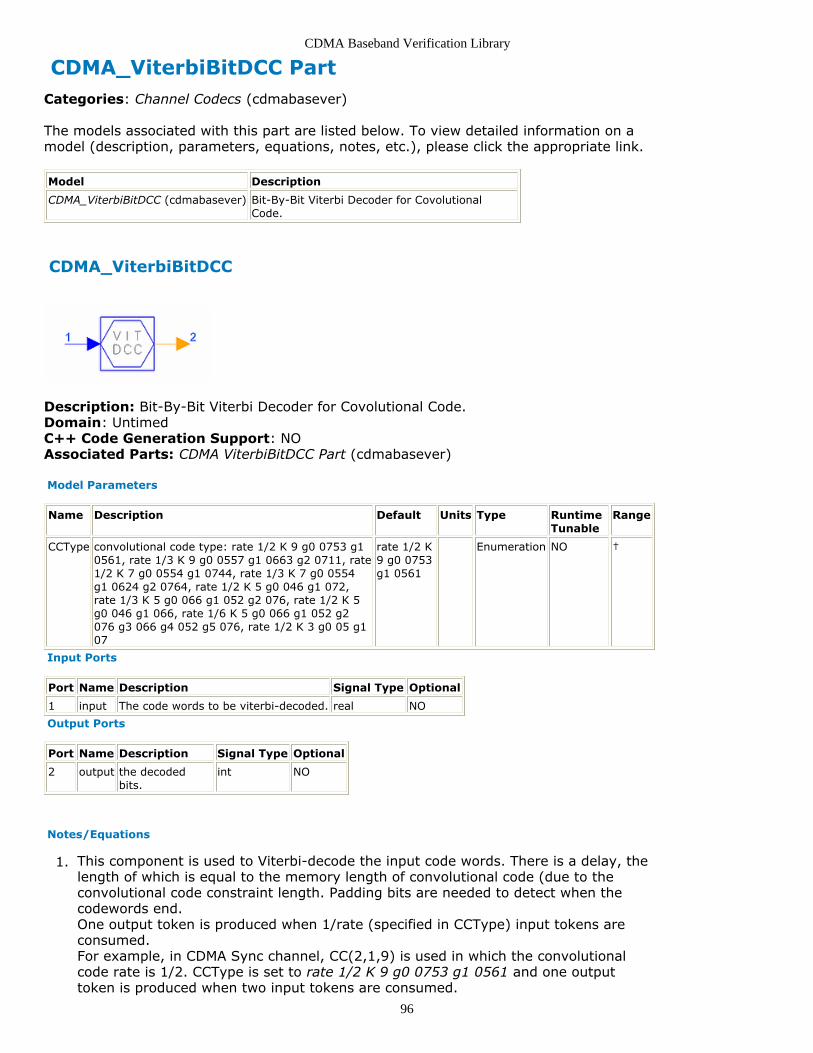
CDMA Baseband Verification Library
96
CDMA_ViterbiBitDCC PartCategories: Channel Codecs (cdmabasever)
The models associated with this part are listed below. To view detailed information on amodel (description, parameters, equations, notes, etc.), please click the appropriate link.
Model Description
CDMA_ViterbiBitDCC (cdmabasever) Bit-By-Bit Viterbi Decoder for CovolutionalCode.
CDMA_ViterbiBitDCC
Description: Bit-By-Bit Viterbi Decoder for Covolutional Code.Domain: UntimedC++ Code Generation Support: NOAssociated Parts: CDMA ViterbiBitDCC Part (cdmabasever)
Model Parameters
Name Description Default Units Type RuntimeTunable
Range
CCType convolutional code type: rate 1/2 K 9 g0 0753 g10561, rate 1/3 K 9 g0 0557 g1 0663 g2 0711, rate1/2 K 7 g0 0554 g1 0744, rate 1/3 K 7 g0 0554g1 0624 g2 0764, rate 1/2 K 5 g0 046 g1 072,rate 1/3 K 5 g0 066 g1 052 g2 076, rate 1/2 K 5g0 046 g1 066, rate 1/6 K 5 g0 066 g1 052 g2076 g3 066 g4 052 g5 076, rate 1/2 K 3 g0 05 g107
rate 1/2 K9 g0 0753g1 0561
Enumeration NO †
Input Ports
Port Name Description Signal Type Optional
1 input The code words to be viterbi-decoded. real NO
Output Ports
Port Name Description Signal Type Optional
2 output the decodedbits.
int NO
Notes/Equations
This component is used to Viterbi-decode the input code words. There is a delay, the1.length of which is equal to the memory length of convolutional code (due to theconvolutional code constraint length. Padding bits are needed to detect when thecodewords end.One output token is produced when 1/rate (specified in CCType) input tokens areconsumed.For example, in CDMA Sync channel, CC(2,1,9) is used in which the convolutionalcode rate is 1/2. CCType is set to rate 1/2 K 9 g0 0753 g1 0561 and one outputtoken is produced when two input tokens are consumed.

CDMA Baseband Verification Library
97
Implementation2.Viterbi Decoding AlgorithmTo make a general component, the following algorithm is used, with CC(2,1,9) as anexample. The generator functions of the code are g0, which equals 753 (octal), andg1, which equals 561 (octal).Because the constraint length is 9, there are 256 possible states in the encoder. Inthe Viterbi decoder all states are represented by a single column of nodes in thetrellis at every symbol instant. At each node in the trellis, there are 2 merging paths;the path with the shortest distance is selected as the survivor.In CDMA systems, the encoded packets are very long; it is impractical to store theentire length of the surviving sequences before determining the information sequencewhen decoding delay and memory is concerned. Instead, only the most recent Linformation bits in each surviving sequence are stored. Once the path with theshortest distance is identified the symbol associated with the path L periods ago isconveyed to the output as a decoded information symbol. Generally, parameter L issufficiently large, normally , for the present symbol of the surviving sequencesto have a minimum effect on the decoding of the L th previous symbol. In CDMAsystems, L=45.The following is the Viterbi algorithm for decoding a CC(n,k,K) code, where K is theconstraint length of convolutional code. In our components, the convolutional code isprocessed with k=1.Branch Metric Calculation
Branch metric , at the J th instant of the path through the trellis is defined as
the logarithm of the joint probability of the received n-bit symbol conditioned on the estimated transmitted n-bit symbol
for the path. That is,
If Rake receiver is regarded as a part of the channel, for the Viterbi decoder thechannel can be considered as an AWGN channel. Therefore,
Path Metric Calculation
The path metric for the path at the J th instant is the sum of the branchmetrics belonging to the path from the first instant to the J th instant. Therefore,
Information Sequence Update
There are merging paths at each node in the trellis and the decoder selects from
the paths , the one having the largest metric, namely,
and this path is known as the survivor.Decoder OutputWhen the two survivors have been determined at the J th instant, the decoderoutputs the ( J-L )th information symbol from its memory of the survivor with the

CDMA Baseband Verification Library
98
largest metric.
References
S. Lin and D. J. Costello, Jr., Error Control Coding Fundamentals and Applications,1.Prentice Hall, Englewood Cliffs NJ, 1983.R. Steele (Editor), Mobile Radio Communication, IEEE Press, June 1995.2.

CDMA Baseband Verification Library
99
CDMA Channel Model Category Contents
CDMA Channel Part (cdmabasever)

CDMA Baseband Verification Library
100
CDMA_Channel PartCategories: Channel Model (cdmabasever)
The models associated with this part are listed below. To view detailed information on amodel (description, parameters, equations, notes, etc.), please click the appropriate link.
Model Description
CDMA_Channel (cdmabasever) Propagation Channel (CDMA) Model
CDMA Channel
Description: Propagation Channel (CDMA) ModelDomain: UntimedC++ Code Generation Support: NOAssociated Parts: CDMA Channel Part (cdmabasever)
Model Parameters

CDMA Baseband Verification Library
101
Name Description Default Units Type RuntimeTunable
Range
BS_X_Position base station antenna X-positioncoordinate, in distance units
0 m Float NO
BS_Y_Position base station antenna Y-positioncoordinate, in distance units
0 m Float NO
BS_Height antenna height above X-Y plane, inlength units
30 m Float NO (0:∞)
MS_X_Position mobile station antenna X-positioncoordinate, in distance units
3 m Float NO
MS_Y_Position mobile station antenna X-positioncoordinate, in distance units
3 m Float NO
MS_Height antenna height above X-Y plane, inlength units
1.7 m Float NO (0:∞)
SpeedType velocity unit: km/hr, miles/hr km/hr Enumeration NO
MS_Vx X component of mobile station velocityvector
0.0 Float NO
MS_Vy Y component of mobile station velocityvector
0.0 Float NO
LinkDirection link direction (Forward: BS->MS,Reverse: MS->BS): Forward, Reverse
Forward Enumeration NO
SampleRate sampling rate of input signal 1.2288e6*4 Hz Float NO
FCarrier carrier frequency of input signal 875e6 Hz Float NO
Type propagation type: NoMultipath,OnePath, TwoPath, ThreePath
NoMultipath Enumeration NO
Pathloss inclusion of large scale pathloss: No,Yes
No Enumeration NO
Environment Radio propagation environment:TypicalUrban, TypicalSuburban,RuralArea, FreeSpace
TypicalUrban Enumeration NO
Seed number to randomize channel output 1234567 Integer NO
Test test port for single path randomfunction: Tap1, Tap2, Tap3
Tap1 Enumeration NO
Input Ports
Port Name Description Signal Type Optional
1 input channel inputsignal
complex NO
Output Ports
Port Name Description Signal Type Optional
2 output channel output signal complex NO
3 test Test port complex NO
Notes/Equations
CDMA_Channel models a multipath channel based on IS-97 specifications. The model1.is a multi-tap filter, each tap having a delay and power. And, each tap is modulatedby a colored noise source.Including the multipath fading and pathloss effects, the output of the channel can bedescribed as
whereα = pathloss attenuation, α≤1βi = relative power of each echo, per specificationτi = relative delay of each echo, plus the direct path delay τ0s(n) = complex envelope input signalgi = random gain function associated with each echo
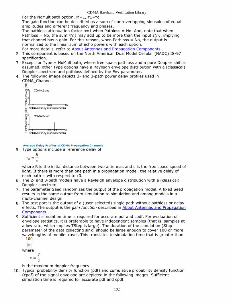
CDMA Baseband Verification Library
102
For the NoMultipath option, M=1, τ1=τoThe gain function can be described as a sum of non-overlapping sinusoids of equalamplitudes and different frequency and phases.The pathloss attenuation factor α=1 when Pathloss = No. And, note that whenPathloss = No, the sum r(n) may add up to be more than the input s(n), implyingthat channel has a gain. For this reason, when Pathloss = No, the output isnormalized to the linear sum of echo powers with each option.For more details, refer to About Antennas and Propagation Components .This component is based on the North American Dual Model Cellular (NADC) IS-972.specification.Except for Type = NoMultipath, where free space pathloss and a pure Doppler shift is3.assumed, other Type options have a Rayleigh envelope distribution with a (classical)Doppler spectrum and pathloss defined by the Env parameter.The following image depicts 2- and 3-path power delay profiles used in4.CDMA_Channel.
Average Delay Profiles of CDMA Propagation Channels
Type options include a reference delay of5.
where R is the initial distance between two antennas and c is the free space speed oflight. If there is more than one path in a propagation model, the relative delay ofeach path is with respect to τ0.The 2- and 3-path models have a Rayleigh envelope distribution with a (classical)6.Doppler spectrum.The parameter Seed randomizes the output of the propagation model. A fixed Seed7.results in the same output from simulation to simulation and among models in amulti-channel design.The test port is the output of a (user-selected) single path without pathloss or delay8.effects. The output is the gain function described in About Antennas and PropagationComponents .Sufficient simulation time is required for accurate pdf and cpdf. For evaluation of9.envelope statistics, it is preferable to have independent samples (that is, samples ata low rate, which implies TStep is large). The duration of the simulation (Stopparameter of the data collecting sink) should be large enough to cover 100 or morewavelengths of mobile travel. This translates to simulation time that is greater than
where
is the maximum doppler frequency.Typical probability density function (pdf) and cumulative probability density function10.(cpdf) of the signal envelope are depicted in the following images. Sufficientsimulation time is required for accurate pdf and cpdf.

CDMA Baseband Verification Library
103
Typical pdf of Signal Envelope
Typical cpdf of Signal Envelope
Parameter Details11.BS_X_Position, BS_Y_Position, BS_Height, MS_X_Position, MS_Y_Position andMS_Height are used to calculate the path loss.SpeedType, MS_Vx and MS_Vy are used to calculate the maximum dopplerfrequency.

CDMA Baseband Verification Library
104
CDMA Receivers Category Contents
CDMA BSFinger Part (cdmabasever)CDMA BSRake Part (cdmabasever)CDMA BSRateconverter Part (cdmabasever)CDMA BSSearcher Part (cdmabasever)CDMA CoherentRake Part (cdmabasever)CDMA FreqErrEstimate Part (cdmabasever)CDMA FreqShifter Part (cdmabasever)CDMA FwdChnlSounder Part (cdmabasever)CDMA FwdRake Part (cdmabasever)CDMA FwdRcvwithAFC Part (cdmabasever)CDMA FwdRcvwithoutAFC Part (cdmabasever)CDMA PathCombiner Part (cdmabasever)CDMA PnCodeAcq Part (cdmabasever)CDMA PnCodeTrack Part (cdmabasever)CDMA RevAGC Part (cdmabasever)

CDMA Baseband Verification Library
105
CDMA_BSFinger PartCategories: Receivers (cdmabasever)
The models associated with this part are listed below. To view detailed information on amodel (description, parameters, equations, notes, etc.), please click the appropriate link.
Model Description
CDMA_BSFinger (cdmabasever) Base Station Rake Finger
CDMA_BSFinger
Description: Base Station Rake FingerDomain: UntimedC++ Code Generation Support: NOAssociated Parts: CDMA BSFinger Part (cdmabasever)
Model Parameters
Name Description Default Units Type RuntimeTunable
Range
MaxPathNum maximum number of paths in Rakecombination
3 Integer NO [1:10]
MaxChannelPathNum range for searching stronger paths 30 Integer NO [12:50]
FingerIndex finger number 0 Integer NO [0:9]
Input Ports
Port Name Description SignalType
Optional
1 RI_in1 This port inputs the user in-phase sequence. real NO
2 RQ_in2 This port inputs the user quadrature-phase sequence. real NO
3 PI_in3 This port inputs the in-phase synchronized spreading code including PNshort code and user long code.
int NO
4 PQ_in4 This port inputs the quadrature-phase synchronized spreading codeincluding PN short code and user long code.
int NO
5 D_in5 This port inputs the path idex of this finger int NO
Output Ports
Port Name Description Signal Type Optional
6 C_out1 This port outputs the detection signal correlation value. real NO
Notes/Equations
This component is used to implement the path tracking and demodulator function in1.the reverse channel, which demodulates the lth path signals using noncoherentdemodulation. 6×64 outputs of C_out1 are produced when 6144 inputs of RI_in1,6144 inputs of RQ_in2, 1536 inputs of PI_in3 and PQ_in4, and 6×MaxPathNumoutputs of D_in5 are consumed.Implementation2.

CDMA Baseband Verification Library
106
Transmitted SignalIn the CDMA reverse channel, the transmitter structure is illustrated in the followingfigure.
IS-95 Transmitter Model Using M-ary Modulation
The transmitted signal of the target transmission link for the ith user can berepresented as
where P is the signal power, is the jth orthogonal Walsh function, T 0 is the time
offset of OQPSK and T 0= T c/2, is the symbol duration, K is the user number,
and is the carrier frequency. and are the pseudo noise sequence ofthe I and Q branches and can be described as:
where and are assumed to be i.i.d. random variables taking values +1 and−1 with probability 1/2. Tc is the chip duration, and p(t) is the chip pulse shape. Here
we specifically use rectangular chip pulse shapes.ChannelThe transmitted signal reaches the receiver via a channel that may have one or morepropagation paths, so the received signal consists of several reflected and scatteredmultipath components. A frequency nonselective multipath fading channel introducesa time-variant amplitude fluctuation, carrier phase jitter, and propagation delay tothe transmitted signal waveform. The complex impulse response of a Rayleigh fadingchannel at baseband can be represented as
where , , and are the lth path amplitude, phase, and delay, respectively.L is the total number of multipath components. We assume that the multipath

CDMA Baseband Verification Library
107
parameters value is small compared to symbol duration, so and can be considered to be constant over the symbol duration.Received SignalThe received signal can be represented as
where
y(t) is the convolution with the transmitted signal and the channel compleximpulse response
is the i th user's random delay of a non-synchronized system.
In the receiver, the received signal is the sum of K users signals, which can beexpressed as
where
is additive white Gaussian noisenc (t) and ns (t) are lowpass Gaussian random processes.
The received signal is converted into the baseband signal. For user informationdemodulation, signals of I, Q phases are despread and then combined using thesquare-law combination algorithm. Refer to [1].The output of this component is input to the CDMA_PathCombiner component forequal gain combining.
References
L. M.A. Jalloul and J. M. Holtzman, "Performance analysis of DS/CDMA with1.noncoherent M-ary orthogonal modulation in multipath fading channels," IEEE JSAC ,Vol. 12, No. 5, June 1994.

CDMA Baseband Verification Library
108
CDMA_BSRake Part Base Station Rake Receiver
Categories: Receivers (cdmabasever)
The models associated with this part are listed below. To view detailed information on amodel (description, parameters, equations, notes, etc.), please click the appropriate link.
Model
CDMA_BSRake (cdmabasever)
CDMA_BSRake
Description: Base Station Rake ReceiverAssociated Parts: CDMA BSRake Part (cdmabasever)
Model Parameters
Name Description Default Units Type Runtime Tunable
FingerNum number of fingers in Rake combination([1:3])
3 none Integer NO
MaxSearchChNum range for searching stronger paths ([12:50]) 40 none Integer NO
Input Ports
Port Name Description Signal Type Optional
1 RI_in1 Terminal: Standard Data PortTerminal
real NO
2 RQ_in2 Terminal: Standard Data PortTerminal
real NO
3 RI_in2 Terminal: Standard Data PortTerminal
int NO
4 PQ_in4 Terminal: Standard Data PortTerminal
int NO
Output Ports
Port Name Description Signal Type Optional
5 R_out1 Terminal: Standard Data PortTerminal
real NO
6 C_out2 Terminal: Standard Data PortTerminal
real NO
7 E_out3 Terminal: Standard Data PortTerminal
real NO
8 N_out4 Terminal: Standard Data PortTerminal
real NO
Notes/Equations
This subnetwork is used to implement Rake receiving. It is a combination of channel1.estimation, noncoherent demodulation, and square-law combination.

CDMA Baseband Verification Library
109
Implementation2.Refer to the following figure. This subnetwork includes CDMA_BSSearcher,CDMA_BSFinger, CDMA_PathCombiner.Input data is PN code and I and Q phase signal data. CDMA_BSSearcher implementsthe multipath search function on the reverse channel to find L maximum-strengthpath signals. The duration between two adjacent paths is one chip. Delay values ofselected paths are output to each noncoherent receiver finger. CDMA_BSFingerimplements path tracking and demodulation, which demodulates the lth path signalsusing noncoherent demodulation. CDMA_PathCombiner implements the pathcombining function, which combines L path signals using equal gain combining. Thesoft decision variables for Viterbi decoder are then calculated.
CDMA_BSRake
References
L. M.A. Jalloul and J. M. Holtzman, "Performance analysis of DS/CDMA with1.noncoherent M-ary orthogonal modulation in multipath fading channels," IEEE JSAC ,Vol. 12, No. 5, June 1994.

CDMA Baseband Verification Library
110
CDMA_BSRateconverter PartCategories: Receivers (cdmabasever)
The models associated with this part are listed below. To view detailed information on amodel (description, parameters, equations, notes, etc.), please click the appropriate link.
Model Description
CDMA_BSRateconverter (cdmabasever) Rake Receiver Output Converter for Sending to ViterbiDecoder.
CDMA_BSRateconverter
Description: Rake Receiver Output Converter for Sending to Viterbi Decoder.Domain: UntimedC++ Code Generation Support: NOAssociated Parts: CDMA BSRateconverter Part (cdmabasever)
Model Parameters
Name Description Default Units Type Runtime Tunable Range
DataRate data rate 1 Integer NO {0,1,2,3}
Input Ports
Port Name Description Signal Type Optional
1 C_in1 The soft decision value inputs real NO
2 Lc_in2 The long code inputs int NO
Output Ports
Port Name Description Signal Type Optional
3 D_out1 The detected sequence outputs. real NO
Notes/Equations
This component is used to convert the frame format of the input sequence according1.to the data burst randomizing algorithm provided in IS-95. The data burstrandomizer generates a masking pattern of zeros and ones that randomly masks theredundant data generated by code repetition. The masking pattern is determined byframe data rate and by a block of 14 bits from the long code. These bits will be thelast 14 bits of long code used for spreading in the previous to the last power controlgroup of the previous frame. 576 outputs of D_out1 are generated when 96 inputs ofC_in1 and 24576 inputs of Lc_in2 are consumed.

CDMA Baseband Verification Library
111
CDMA_BSSearcher PartCategories: Receivers (cdmabasever)
The models associated with this part are listed below. To view detailed information on amodel (description, parameters, equations, notes, etc.), please click the appropriate link.
Model Description
CDMA_BSSearcher (cdmabasever) Base Station RakeSearcher
CDMA_BSSearcher
Description: Base Station Rake SearcherDomain: UntimedC++ Code Generation Support: NOAssociated Parts: CDMA BSSearcher Part (cdmabasever)
Model Parameters
Name Description Default Units Type RuntimeTunable
Range
MaxPathNum maximum number of paths in Rakecombination
3 Integer NO [1:10]
MaxChannelPathNum range for searching strongest paths 30 Integer NO [9:50]
Input Ports
Port Name Description SignalType
Optional
1 RI_in1 This port inputs the user in-phase sequence. real NO
2 RQ_in2 This port inputs the user quadrature-phase sequence. real NO
3 PI_in3 This port inputs the in-phase synchronized spreading code including PNshort code and user long code.
int NO
4 PQ_in4 This port inputs the quadrature-phase synchronized spreading codeincluding PN short code and user long code.
int NO
Output Ports
Port Name Description Signal Type Optional
5 D_out1 This port outputs the delay values of each selected path multiple int NO
Notes/Equations
This component performs the multipath searching function on the reverse channel to1.find L maximum-strength path signals. The duration between two adjacent paths isone-fourth chip. Delay values of selected paths are output to each noncoherentreceiver finger. 6×MaxPathNum outputs of D_out1 are produced when 6144 RI_in1,6144 RQ_in2, 1536 PI_in3, and 1536 PQ_in4 inputs are consumed.Implementation2.Transmitted Signal

CDMA Baseband Verification Library
112
In the CDMA reverse channel, a transmitter structure is shown in the following figure.
IS-95 Transmitter Using M-ary Modulation
The transmitted signal of the target transmission link for the ith user can berepresented as
where P is signal power, is jth orthogonal Walsh function, T 0 is OQPSK time
offset, and T 0 = Tc /2, Tw is symbol duration, K is user number, and is the
carrier frequency. and are the I and Q branch pseudo noise sequencesand can be described as
where and are assumed to be i.i.d. random variables taking values +1 and−1 with probability 1/2. Tc is the chip duration, and p(t) is the chip pulse shape. Here
we specifically use rectangular chip pulse shapes.ChannelThe transmitted signal reaches the receiver via a channel that may include one ormore propagation paths, so the received signal consists of several reflected andscattered multipath components. A frequency nonselective multipath fading channelintroduces a time-variant amplitude fluctuation, carrier phase jitter, and propagationdelay to the transmitted signal waveform. The complex impulse response of aRayleigh fading channel at baseband can be represented as
where , , and are lth path amplitude, phase, and delay, respectively. L isthe total number of multipath components. We assume that the multipath

CDMA Baseband Verification Library
113
parameters value is small compared to symbol duration, so that and canbe considered to be constant over the symbol duration.Received SignalThe received signal can be represented as
where
y(t) is the convolution with the transmitted signal and the channel compleximpulse response
is the i th user's random delay of a non-synchronized system.
In the receiver, the received signal is the sum of K users signals, which can beexpressed as:
where
is additive white Gaussian noisenc (t) and ns (t) are lowpass Gaussian random processes.
The received signal is converted into the baseband signal, then the I- and Q-phasesignals are despread. Non-coherent demodulation with square-law combination isused to find the channel with the strongest paths.Path Searching in the Rake ReceiverIn the reverse link, according to the IS-98 Standard, maximum channel delay is 14.5µ (which is approximately 18 Tc ), and the delay caused by filters in transceivers is
12 Tc. So, in this component the path search range should be >30 Tc. Path resolution
is one chip time ( Tc = 0.813 µ) and search accuracy is 1/4 chip. Suitable paths with
the strongest signals from all paths in the CDMA channel are selected and signals onthe weaker paths are ignored.In IS-95 systems, path selection in the reverse link differs from the forward link. Inforward link, each path strength can be estimated through the pilot channel andcoherent receiver can be used. In reverse link, no pilot channel exists, so the non-coherent receiving technique is used.In the reverse Rake receiver, the signal is despread by PN code, then correlated with64 Walsh codes. The maximum correlation value among all 64 correlations isconsidered to be the path strength.After all path strengths are estimated, the first L(L<10, default value 3) paths withmaximum strength are selected. Path indexes of L maximum paths are output toCDMA_BSFinger.

CDMA Baseband Verification Library
114
References
TIA/EIA/IS-95-A, Mobile Station-Base Station Compatibility Standard for Dual-Mode1.Wideband Spread Spectrum Cellular System, May 1995.L. M.A. Jalloul and J. M. Holtzman, "Performance analysis of DS/CDMA with2.noncoherent M-ary orthogonal modulation in multipath fading channels," IEEE JSAC ,Vol. 12, No. 5, June 1994.W. Zhuang, "Noncoherent Hybrid Parallel PN Code Acquisition for CDMA Mobile3.Communications," IEEE Transaction on Vehicular Technology , Vol 45, No. 4, Nov,1996.R. A. Birgenheier, "Overview of Code-Domain Power, Timing, and Phase4.Measurements," Hewlett-Packard Journal , Feb 1996.W. Y. C. Lee, "Overview of cellular CDMA," IEEE Trans. Vehic. Tech ., Vol. VT-40, No.5.2, pp. 291-3-2, May 1991.R. F. W. Coates, G. J. Janacek, and K. V. Keverm, "Monte Carlo simulation and6.random number generation," IEEE J. Select. Area Commun ., Vol. 6, No. 1, pp 58-66,Jan. 1988.R. Padovani, "Reverse link performance of IS-95 based cellular systems," IEEE7.personal Commun ., Vol. 1, No. 3, pp. 28-34, 1994.A. J. Viterbi, CDMA: Principles of Spread Spectrum Communication, Wesley8.Publishing Company, Apr. 1995.J. G. Proakis, Digital Communications , McGraw-Hill, 3rd edition, 1995.9.TIA/EIA/IS-98, Recommended Minimum Performance Standards for Dual-Mode10.Wideband Spread Spectrum Cellular Mobile Stations , Dec. 1994.

CDMA Baseband Verification Library
115
CDMA_CoherentRake PartCategories: Receivers (cdmabasever)
The models associated with this part are listed below. To view detailed information on amodel (description, parameters, equations, notes, etc.), please click the appropriate link.
Model Description
CDMA_CoherentRake (cdmabasever) Coherent Rake Receiver.
CDMA_CoherentRake
Description: Coherent Rake Receiver.Domain: UntimedC++ Code Generation Support: NOAssociated Parts: CDMA CoherentRake Part (cdmabasever)
Model Parameters
Name Description Default Units Type RuntimeTunable
Range Symbol
NSymblChE number of consumedsymbols for channelestimation in each firing
8 Integer NO 2<sup>n</sup>,n=0,...,9
N
NSymblIni number of initial ineffectiveinput symbols from thepreceding model
0 Integer NO NSymblChE * n,n=0,2
NFinger number of Rake receiverfinger
3 Integer NO [1:3] (up to thechannel)
L
PN_Offset offset (in terms of chips) ofPN code between base andmobile stations
0 Integer NO 64 * n, n=0,...,512
SampleRatio number of samples per chip 4 Integer NO 4 R
WalshIndex Walsh code index 3 Integer NO [0:63]
Input Ports
Port Name Description Signal Type Optional
1 sigIn equivalent baseband received signal. complex NO
4 dlIdx multipath delays for every finger. int NO
5 chPrm multipath channel parameters for every finger. complex NO
Output Ports
Port Name Description Signal Type Optional
2 dlOut multipath delays for every finger. int YES
3 sigOut multipath channel parameters for every finger. complex NO
Notes/Equations
This component is used to implement coherent Rake receiver for IS95 forward link. It1.

CDMA Baseband Verification Library
116
despreads the signal and coherently combines the signal despread from multipathsusing maximum ratio combining. Each firing, N output tokens are produced for ( N×64× R ) input tokens consumed. The real part of the output complex signal can beused as the decision variable or input to the decoder.Implementation2.
Principle Diagram of Coherent Rake Receiver
For implementation refer to CDMA_FwdChnlSounder.The CDMA_CoherentRake output is implemented by
where Re denotes taking real part.
For BPSK the bit error probability after combining for a known channel is
For MPS, the bit energy is generally denoted by
For BPSK the energy equals symbol energy Esq.
References
V. Barnasconi, Receiver Architectures for the Down-link in a DS-CDMA Mobile System1., IEEE CD-ROM 1994.U. Fawer, "A Coherent Spread-Spectrum Diversity-Receiver with AFC for Multipath2.Fading Channels," IEEE Trans. on Comm. Vol.42, pp. 1300-1311, 1994.

CDMA Baseband Verification Library
117
CDMA_FreqErrEstimate PartCategories: Receivers (cdmabasever)
The models associated with this part are listed below. To view detailed information on amodel (description, parameters, equations, notes, etc.), please click the appropriate link.
Model Description
CDMA_FreqErrEstimate(cdmabasever)
Carrier Frequency Error Estimation of Received Signal Relative to BSTransmitter.
CDMA_FreqErrEstimate
Description: Carrier Frequency Error Estimation of Received Signal Relative to BSTransmitter.Domain: UntimedC++ Code Generation Support: NOAssociated Parts: CDMA FreqErrEstimate Part (cdmabasever)
Model Parameters
Name Description Default Units Type RuntimeTunable
Range Symbol
NSymblChE number of consumedsymbols for channelestimation in each firing
8 Integer NO 2<sup>n</sup>,n=0,...,9
N
NSymblIni number of initial ineffectiveinput symbols from thepreceding model
0 Integer NO NSymblChE * n,n=0,2
NFinger number of Rake receiverfinger
3 Integer NO [1:3] (up to thechannel)
L
PN_Offset offset (in terms of chips) ofPN code between base andmobile stations
0 Integer NO 64 * n, n=0,...,512
Distance distance between transmitand receive antennas
7.0 m Integer NO [0.0:∞) D
SampleRatio number of samples per chip 4 Integer NO 4 R
Input Ports
Port Name Description Signal Type Optional
1 sigIn equivalent baseband receivedsignal.
complex NO
Output Ports
Port Name Description Signal Type Optional
2 dlOut multipath delays for every finger. int YES
3 sigOut multipath channel parameters for every finger. complex YES
4 fErr estimated digital angle frequency error. real NO
Notes/Equations

CDMA Baseband Verification Library
118
This component is used to estimate carrier frequency error of the received signal1.relative to the BS transmitter. Frequency error is caused by Doppler effect or localoscillator inaccuracy. Each firing, 2 N output tokens are produced for 2 N ×WalshCodeLength × R input tokens consumed.Implementation2.
Carrier Frequency Error Estimation
The frequency offset estimate at time t = kT is:
where denotes the number of symbols forming the observation interval.
Or, let =1 and use a loop filter to implement tracking of small frequency offset.The loop filter transfer function is:
where 0<K<<1. Frequency estimation for this type of scheme is written as:
The algorithm for frequency offset (Δ f ) detector is shown in the previous equationsfor initial acquisition and tracking, respectively.Angle frequency is used to avoid operation with π, which is shown as:

CDMA Baseband Verification Library
119
To further simplify the operation, digital angle frequency Δω[k] at time t = kT with Tas sampling interval is used as output of the frequency offset detector:
The detected range of the digital angle frequency error Δω should be:
References
V. Barnasconi, Receiver Architectures for the Down-link in a DS-CDMA Mobile1.System, IEEE CD-ROM 1994.U. Fawer, "A Coherent Spread-Spectrum Diversity-Receiver with AFC for Multipath2.Fading Channels," IEEE Trans. on Comm., Vol.42, pp. 1300-1311, 1994.Z. Wenan and Z. Xiaoguang, "Approach on AFC of mobile station in vehicle for IS-95A3.CDMA cellular mobile communication system," The Proceedings of the fifth ChinaYouth Communication Academic Conference, pp. 483-486, 1997.

CDMA Baseband Verification Library
120
CDMA_FreqShifter PartCategories: Receivers (cdmabasever)
The models associated with this part are listed below. To view detailed information on amodel (description, parameters, equations, notes, etc.), please click the appropriate link.
Model Description
CDMA_FreqShifter (cdmabasever) Carrier Frequency Offset Shifter.
CDMA_FreqShifter
Description: Carrier Frequency Offset Shifter.Domain: UntimedC++ Code Generation Support: NOAssociated Parts: CDMA FreqShifter Part (cdmabasever)
Model Parameters
Name Description Default Units Type RuntimeTunable
Range Symbol
NConsume number of received signal tokensconsumed in one firing (in terms ofsamples for this model)
4096 Integer NO † Ns
NfshftInputPeriod number of input signal tokens to beshifted based on the frequency shiftvalue
256 Integer NO 256 NT
NIniFire number of initial ineffective firings,=3 if used after AFC part
3 Integer NO [0:∞)
Input Ports
Port Name Description SignalType
Optional
1 fShft digital angle frequency value ( in terms of radians ) to be shifted perdata.
real NO
2 sigIn equivalent baseband received signal. complex NO
Output Ports
Port Name Description Signal Type Optional
3 sigOut signal after frequencycorrecting.
complex NO
Notes/Equations
This component is used to adjust the frequency offset. It can correct the frequency1.error in the receiver input according to the fShft value produced byCDMA_FreqErrEstimate. Each firing, Ns output tokens are produced for Ns inputtokens consumed.Implementation2.

CDMA Baseband Verification Library
121
Principle Diagram of Frequency Error Shifter
The principle of the frequency shifter used in the receiver can be shown as:
In IS-95, the sample interval of the received signal
where T c denotes the length of a code chip. Thus the discrete expression of the
equation above is
where the digital angle frequency and N T denotes the number
of samples for duration T.
As mentioned, the output of the frequency offset (Δf) detector uses the digital anglefrequency Δω[k] at time t = kT with T as sampling interval. For coordination betweenconnected components, the equation above is rewritten as:
where

CDMA Baseband Verification Library
122
CDMA_FwdChnlSounder PartCategories: Receivers (cdmabasever)
The models associated with this part are listed below. To view detailed information on amodel (description, parameters, equations, notes, etc.), please click the appropriate link.
Model Description
CDMA_FwdChnlSounder(cdmabasever)
Channel Sounder on Pilot Channel for IS95 CDMA System Forward LinkReceiver.
CDMA_FwdChnlSounder
Description: Channel Sounder on Pilot Channel for IS95 CDMA System Forward LinkReceiver.Domain: UntimedC++ Code Generation Support: NOAssociated Parts: CDMA FwdChnlSounder Part (cdmabasever)
Model Parameters

CDMA Baseband Verification Library
123
Name Description Default Units Type RuntimeTunable
Range Symbol
NSymblChE number ofconsumed symbolsfor channelestimation in eachfiring
8 Integer NO 2<sup>n</sup>,n=0,...,9
N
NSymblIni number of initialineffective inputsymbols from thepreceding model
0 Integer NO NSymblChE * n,n=0,2
NFinger number of Rakereceiver finger
3 Integer NO [1:3] (up to thechannel)
L
PN_Offset offset (in terms ofchips) of PN codebetween base andmobile stations
0 Integer NO 64 * n,n=0,...,512
Distance distance betweentransmit andreceive antennas
7.0 m Integer NO [0.0:∞) D
Mode model modefunction:MultipathSearcherand Test:MultipathSearcher,Test
MultipathSearcher Enumeration NO
SampleRatio number ofsamples per chip
4 Integer NO 4 R
MaxChSpread maximummultipath channeldelay spread
1.45e-5 s Float NO 14.5e-6 τmax
ChipRate transmitted chiprate, in terms ofchips per second
1.2288e6 Float NO 1.2288e6 S
Input Ports
Port Name Description Signal Type Optional
1 sigIn equivalent baseband receivedsignal.
complex NO
Output Ports
Port Name Description Signal Type Optional
2 dlOut multipath delays for every finger. int NO
3 sigOut multipath channel parameters for every finger. complex NO
Notes/Equations
This model is used for channel estimation for IS-95 forward link pilot channel.1.When Mode=MultipathSearcher, L dlOut and L sigOut tokens are produced for Ncp (Ncp = N × WalshCodeLength × R ) sigIn tokens consumed each firing. The outputmultipath delays and channel coefficients are selected by sorting correlation valuesfor each possible delay position in the search window. Search window width isdetermined by MaxChSpread and Distance.When Mode=Test, W dlOut and W sigOut tokens are produced for Ncp sigIn tokensconsumed each firing, where W denotes search window width (in terms of samples).The total channel profile (multipath delays and channel coefficients) is output.For channel estimation, N must be small enough to track channel change, and largeenough to determine accuracy; N =8 is recommended for a 3-path CDMA channelwith 50km/hr speed.CDMA_CoherentRake, CDMA_FreqErrEstimate, and CDMA_FreqShifter componentsrelated to forward link Rake receiver are used with CDMA_FwdChnlSounder.

CDMA Baseband Verification Library
124
Implementation2.The following figure represents the basic forward channel sounder block diagram.
Forward Channel Sounder Block Diagram
In IS-95, the phase noise sequence period Q is 32768. The total phase range isdenoted by D.
D = Q × SampleRatio = 4 Q
L path delays ( Ti, i = 1, 2, ..., L ) with the strongest energy are chosen; path energyis based on the pilot channel.Because the maximum multipath delay is much smaller than symbol duration T (64chips), the detection range of the multiple searcher should be smaller than T.CDMA_FwdChnlSounder estimates the energy of paths in the range, selects Lstrongest paths, obtains their delays, and stores their correlation values as thecorresponding channel coefficients used by the receiver.
References
F. Li and H. Xiao and J. Yang, On Channel Estimation for Rake Receiver in a mobile1.multipath fading channel, IEEE CD-ROM, 1994.W. Zhuang, "Noncoherent Hybrid Parallel PN Code Acquisition for CDMA Mobile2.Communications," IEEE Transaction on Vehicular Technology, Vol.45, No.4, pp. 643-656, Nov. 1996.U. Fawer, "A Coherent Spread-Spectrum Diversity-Receiver with AFC for Multipath3.Fading Channels," IEEE Trans. on Comm., Vol.42, pp. 1300-1311, 1994.A. J. Viterbi, Principles of Spread Spectrum Communication, The Peoples Posts &4.Telecommunications Publishing, 1995.TIA/EIA/IS-95-A, Mobile Station-Base Station Compatibility Standard for Dual-Mode5.Wideband Spread Spectrum Cellular System, May 1995.

CDMA Baseband Verification Library
125
CDMA_FwdRake Part IS95A CDMA Forward Link Rake Receiver
Categories: Receivers (cdmabasever)
The models associated with this part are listed below. To view detailed information on amodel (description, parameters, equations, notes, etc.), please click the appropriate link.
Model
CDMA_FwdRake (cdmabasever)
CDMA_FwdRake
Description: IS95A CDMA Forward Link Rake ReceiverAssociated Parts: CDMA FwdRake Part (cdmabasever)
Model Parameters
Name Description Default Units Type RuntimeTunable
NSymblChEst number of symbols for channel estimation(2<sup>n</sup>, n=0,...,9)
8 none Integer NO
NSymblInputIni initial symbol number (NSymblChEst * n, n=0,2) 0 none Integer NO
FingerNumber number of Rake receiver finger ([1:3] (up to thechannel))
3 none Integer NO
PilotPN_Offset offset (in terms of chips) of PN code between baseand mobile stations (64 * n, n=0,...,512)
0 none Integer NO
Distance maximum distance between transmit and receiveantennas, in km ([0.0:inf))
7 none Float NO
UserChannelIndex Walsh code index ([0:63]) 3 none Integer NO
Input Ports
Port Name Description Signal Type Optional
1 sigIn Terminal: Standard Data PortTerminal
complex NO
Output Ports
Port Name Description Signal Type Optional
2 sigOut Terminal: Standard Data PortTerminal
complex NO
Notes/Equations
The basic function of this subnetwork is to implement the IS-95A forward link1.receiver, which includes demodulating and despreading signal coherently by Rakereceiver using maximum ratio combining and multipath delay estimation, andchannel coefficient estimation (attenuation and phase).Implementation2.As shown in the following figure, this subnetwork includes CDMA_FwdChnlSounder,

CDMA Baseband Verification Library
126
CDMA_CoherentRake.
CDMA_FwdRake Network
CDMA_FwdChnlSounder is used to implement channel sounding for IS95A forwardlink using a pilot channel. Output multipath delays and channel coefficients are sortedby correlation values for each possible delay position in the search window; searchwindow width is determined by the system parameter. For channel estimation, Nmust be small enough to track channel change, and large enough to determineaccuracy; N =8 is recommended for a 3-path CDMA channel with 50 km/hr speed.CDMA_CoherentRake is used to implement coherent Rake receiver for IS95A forwardlink. It despreads the signal using multipath delays and channel coefficients outputfrom CDMA_FwdChnlSounder, and coherently combines the signal despread frommultipaths using maximum ratio combining. The real part of the output complexsignal can be used as the decision variable or input to the decoder.
References
TIA/EIA/IS-95-A, Mobile Station-Base Station Compatibility Standard for Dual-Mode1.Wideband Spread Spectrum Cellular System, May 1995.
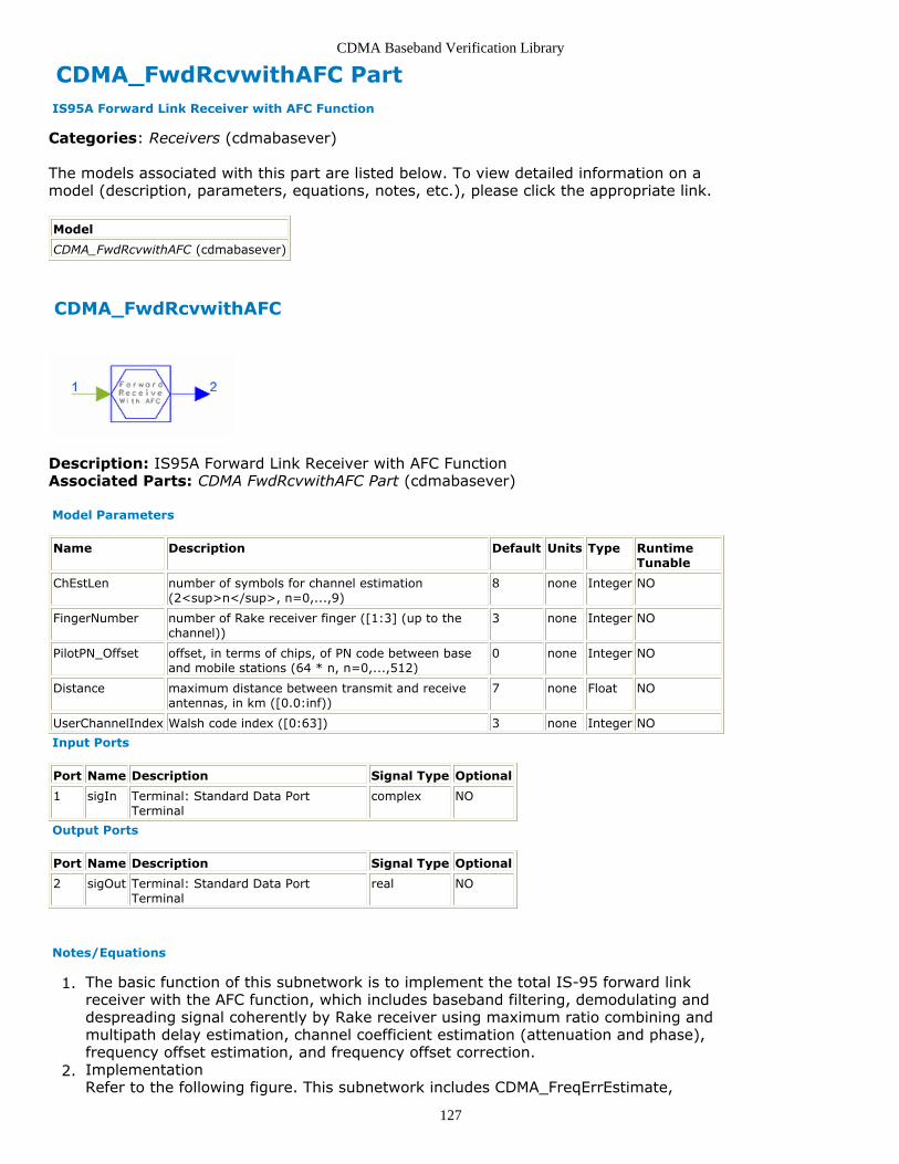
CDMA Baseband Verification Library
127
CDMA_FwdRcvwithAFC Part IS95A Forward Link Receiver with AFC Function
Categories: Receivers (cdmabasever)
The models associated with this part are listed below. To view detailed information on amodel (description, parameters, equations, notes, etc.), please click the appropriate link.
Model
CDMA_FwdRcvwithAFC (cdmabasever)
CDMA_FwdRcvwithAFC
Description: IS95A Forward Link Receiver with AFC FunctionAssociated Parts: CDMA FwdRcvwithAFC Part (cdmabasever)
Model Parameters
Name Description Default Units Type RuntimeTunable
ChEstLen number of symbols for channel estimation(2<sup>n</sup>, n=0,...,9)
8 none Integer NO
FingerNumber number of Rake receiver finger ([1:3] (up to thechannel))
3 none Integer NO
PilotPN_Offset offset, in terms of chips, of PN code between baseand mobile stations (64 * n, n=0,...,512)
0 none Integer NO
Distance maximum distance between transmit and receiveantennas, in km ([0.0:inf))
7 none Float NO
UserChannelIndex Walsh code index ([0:63]) 3 none Integer NO
Input Ports
Port Name Description Signal Type Optional
1 sigIn Terminal: Standard Data PortTerminal
complex NO
Output Ports
Port Name Description Signal Type Optional
2 sigOut Terminal: Standard Data PortTerminal
real NO
Notes/Equations
The basic function of this subnetwork is to implement the total IS-95 forward link1.receiver with the AFC function, which includes baseband filtering, demodulating anddespreading signal coherently by Rake receiver using maximum ratio combining andmultipath delay estimation, channel coefficient estimation (attenuation and phase),frequency offset estimation, and frequency offset correction.Implementation2.Refer to the following figure. This subnetwork includes CDMA_FreqErrEstimate,

CDMA Baseband Verification Library
128
CDMA_FreqShifter and CDMA_FwdRake.
CDMA_FwdRcvwithAFC Network
The channel input signal is input into CDMA_FreqErrEstimate; here it is used toestimate the carrier frequency error of the received signal relative to the base stationtransmitter caused by Doppler effect or local oscillator inaccuracy. The estimationresult is input into CDMA_FreqShifter to adjust frequency offset of the original signal.The corrected complex signal is then input into subnetwork CDMA_FwdRake fordespreading.
References
TIA/EIA/IS-95-A, Mobile Station-Base Station Compatibility Standard for Dual-Mode1.Wideband Spread Spectrum Cellular System, May 1995.

CDMA Baseband Verification Library
129
CDMA_FwdRcvwithoutAFC Part IS95 Forward Link Receiver without AFC Function
Categories: Receivers (cdmabasever)
The models associated with this part are listed below. To view detailed information on amodel (description, parameters, equations, notes, etc.), please click the appropriate link.
Model
CDMA_FwdRcvwithoutAFC (cdmabasever)
CDMA_FwdRcvwithoutAFC
Description: IS95 Forward Link Receiver without AFC FunctionAssociated Parts: CDMA FwdRcvwithoutAFC Part (cdmabasever)
Model Parameters
Name Description Default Units Type RuntimeTunable
ChEstLen number of symbols for channel estimation(2<sup>n</sup>, n=0,...,9)
8 none Integer NO
FingerNumber number of Rake receiver fingers ([1:3] (up to thechannel))
3 none Integer NO
PilotPN_Offset offset, in terms of chips, of PN code between baseand mobile stations (64 * n, n=0,...,512)
0 none Integer NO
Distance maximum distance between transmit and receiveantennas, in km ([0.0:inf))
7 none Float NO
UserChannelIndex Walsh code index ([0:63]) 3 none Integer NO
NSymblInputIni number of initial ineffective input symbols frompreceding components ([0:inf))
0 none Integer NO
Input Ports
Port Name Description Signal Type Optional
1 sigIn Terminal: Standard Data PortTerminal
complex NO
Output Ports
Port Name Description Signal Type Optional
2 sigOut Terminal: Standard Data PortTerminal
real NO
Notes/Equations
The basic function of this subnetwork is to implement the total IS-95 forward link1.receiver without AFC function, which includes baseband filtering, demodulating anddespreading signal coherently by Rake receiver using maximum ratio combining andmultipath delay estimation, channel coefficient estimation (attenuation and phase).Implementation2.

CDMA Baseband Verification Library
130
Refer to the following figure. This subnetwork includes CDMA_FwdRake.
CDMA_FwdRcvwithoutAFC Network
The complex channel signal is baseband filtered, then input into CDMA_FwdRake fordespreading.
References
TIA/EIA/IS-95-A, Mobile Station-Base Station Compatibility Standard for Dual-Mode1.Wideband Spread Spectrum Cellular System, May 1995.

CDMA Baseband Verification Library
131
CDMA_PathCombiner PartCategories: Receivers (cdmabasever)
The models associated with this part are listed below. To view detailed information on amodel (description, parameters, equations, notes, etc.), please click the appropriate link.
Model Description
CDMA_PathCombiner (cdmabasever) Base station Path Combiner
CDMA_PathCombiner
Description: Base station Path CombinerDomain: UntimedC++ Code Generation Support: NOAssociated Parts: CDMA PathCombiner Part (cdmabasever)
Model Parameters
Name Description Default Units Type RuntimeTunable
Range
MaxPathNum maximum number of paths in rakecombination
3 Integer NO [1:10]
Input Ports
Port Name Description Signal Type Optional
1 Cr_in1 This port inputs the user in-phase sequence. multiple real NO
Output Ports
Port Name Description SignalType
Optional
2 soft_decision_var_out This port outputs the soft decision variables for Viterbidecoder.
real NO
3 C_out2 This port outputs the detection signal correlation value. real NO
4 E_out3 This port outputs the Bit Energy estimation. real NO
5 N_out4 This port outputs the Interference plus Noise estimation. real NO
Notes/Equations
This component is used to implement the path combining function in the reverse1.channel, which combines L path signals using equal gain combining. Soft decisionvariables for Viterbi decoder are calculated.Implementation2.Path CombiningThe selected L multipath signals are combined using equal gain combining.In Rake receiver, each finger demodulates a different propagation of the signal. Ineach finger, the signal is correlated with each possible mapping of data to produce acorresponding correlation energy value. Associated with each correlation energyvalue is an index value of Walsh code. Correlation energy values of the same index

CDMA Baseband Verification Library
132
from multiple fingers are then summed.In this equal gain combining Rake receiver, the hard decision variables of kth userare
where
In this component, the receiver uses a maximum-likelihood decision rule.Decision Output UnitThe maximum signal among 64 Walsh correlator outputs is selected. According tomaximum-likelihood decision, the binary code of the number of the Walsh function isthe recovered data of Rake receiver for Viterbi decoder using hard-decisionalgorithm.Soft Decision Data CalculationSoft decision data for Viterbi decoder is calculated according to the method in [1]. Itsearches for a maximum energy level value in each of two subsets of a given set ofWalsh symbol indexes and associated energy level values and calculates thedifference of the two maximum energy level values to form a soft decision outputvalue. For example, for ith bit of a sequence a1a2...aj, the soft decision value is
where
Mi = {all of m: ai =0},
= {all if m: ai =1}
The two subsets are identified by the binary value (0 or 1) of a given digital of thebinary equivalent of the Walsh symbol index. The soft decision output value reflects ameasure of confidence of the value of the corresponding digit of the original signal.SINR MeasurementFor SINR measurement, signal power, interference, and noise power must becalculated in a fixed time interval. A frame time interval is used to obtain the desiredsignal power, interference, and noise power.Signal power can be acquired as:
where Nn expresses the SINR measurement symbol number, Smax is the symbol
detection variable, max corresponds to the Walsh code index that is the maximumcorrelation value among the 64 Walsh correlation values.So the interference plus noise power is:

CDMA Baseband Verification Library
133
where PI is the sum of all Walsh code correlation values excluding the maximum
value. Therefore,
References
A. J. Viterbi, CDMA: Principles of Spread Spectrum Communication, Wesley1.Publishing Company, 1995.

CDMA Baseband Verification Library
134
CDMA_PnCodeAcq PartCategories: Receivers (cdmabasever)
The models associated with this part are listed below. To view detailed information on amodel (description, parameters, equations, notes, etc.), please click the appropriate link.
Model Description
CDMA_PnCodeAcq (cdmabasever) PN Code Acquisition
CDMA_PnCodeAcq
Description: PN Code AcquisitionDomain: UntimedC++ Code Generation Support: NOAssociated Parts: CDMA PnCodeAcq Part (cdmabasever)
Input Ports
Port Name Description Signal Type Optional
1 in1 input sequence int NO
Output Ports
Port Name Description Signal Type Optional
2 out1 output sequencephase
int NO
Notes/Equations
This component is used to perform the acquisition function of the pseudo noise1.sequence (PN code) of the input signal, which includes the matched filter correlator,local pseudo-noise subsequence generator, synchronization control scheme unit, anddecision unit. Each firing, one output token is generated when 1280 input tokens areconsumed.Implementation2.Generally, PN code synchronization consists of acquisition and tracking. PN codeacquisition finishes the coarse synchronization of PN code; tracking accuratelymodifies the synchronization.The noncoherent partial parallel PN code acquisition method is used (see thefollowing figure), which can reduce acquisition time.

CDMA Baseband Verification Library
135
Noncoherent Partial Parallel PN Code Acquisition System
Assuming input signal is r(t), and the local PN code subsequence can be defined as:
where aI (t) and aQ (t) are the PN sequence of I and Q branches, p(t) is the PN code
waveform defined as a unit rectangular pulse over [0, Tc ]. M is the length of the
local PN code subsequence as well as the correlation scope.The previous sequence are correlated in the matched filter correlator; the correlationexpressions are
where the matched filter uses the tapped delay line structure shown in the followingfigure, the input signal shifts in the tapped delay line unit and multiply with the PNcode subsequence, and then summed to export.
I-Q Noncoherent Correlator Structure

CDMA Baseband Verification Library
136
I-Q Noncoherent Correlator Structure
Partial correlation of the incoming and locally generated codes is performed atbaseband in the in-phase and quadrature arms, each arm is squared and added as adecision variable eij for the ith searching in the jth branch over duration T=MTc.
An input code length L (L= M×N1×N2) is assumed. The uncertainty region of theinput code phase is divided into sub-regions each having length M with N 1and N 2being integers. N 1 and N 2 are design parameters describing the numbers of paralleland serial acquisition searches, respectively. Each correlator has one of the subcodesof length M as a reference code input. The code uncertainty region of eachsubsequence is discretized with a Δ step size, which is normalized to chip interval Tc,
and each subsequence contains M /Δ discrete PN code phases.In the partial noncoherent correlation at each correlator, the number of taps on thedelay line is M /Δ with a Δ Tc delay between successive taps. The incoming codephase uncertainty region is searched in discrete steps.Over each noncoherent correlation period T there are MTc /Δ input data samples.
Each new input data sample is collected with N 1 subcodes simultaneously loaded in N1 parallel correlators. The process repeats M /Δ times, each time with a unique codephase offset between the incoming PN code and the subcode loaded in any correlator,until all possible PN code phases corresponding to N 1 subcodes are tested once. Thecorrelators generate MN 1/Δ decision variables over the period, corresponding to MN1/Δ possible phases.In the next period of duration T, the N 1 noncoherent correlators are loaded with anew group of PN subcodes corresponding to other MN 1/Δ possible input codephases; the correlation process continues until a coarse code phase alignment isdetected.In this way, over a period of N 2 T, the N 1 parallel noncoherent correlators generate L/Δ decision variables corresponding to all possible discrete PN code phases of theinput signal.
Matched Filter Correlator Structure
After correlation, each noncoherent partial correlation value is squared and summedas follows:
where eij is the output to enter into the decision unit, which is according to the

CDMA Baseband Verification Library
137
threshold value to determine whether the acquisition action goes to verification modeH 1 or to the repeated search mode H 0. Selection of the largest eij is shown as.
On the other hand, the decision expression is
In PN code acquisition, a coarse alignment decision is made after MN 1/Δ discretecode phases are tested once. In other words, after each interval of length T, thedecision is made according to MN 1/Δ decision variables. The decision device stores [Ε ], the corresponding phase of the subcode that is tentatively assumed to becoarsely aligned with the received PN code signal ( H 1); otherwise, coarse alignmentis not achieved ( H 0). In the next period T, the search process is repeated with thenext group of possible references subdued until a tentative H 1 state is assumed.The verification mode begins.
References
W. Zhuang, "Noncoherent Hybrid Parallel PN Code Acquisition for CDMA Mobile1.Communications," IEEE Transaction on Vehicular Technology, Vol. 45, No. 4, Nov.1996.

CDMA Baseband Verification Library
138
CDMA_PnCodeTrack PartCategories: Receivers (cdmabasever)
The models associated with this part are listed below. To view detailed information on amodel (description, parameters, equations, notes, etc.), please click the appropriate link.
Model Description
CDMA_PnCodeTrack (cdmabasever) PN Code Tracking
CDMA_PnCodeTrack
Description: PN Code TrackingDomain: UntimedC++ Code Generation Support: NOAssociated Parts: CDMA PnCodeTrack Part (cdmabasever)
Input Ports
Port Name Description Signal Type Optional
1 in1 input sequence int NO
Output Ports
Port Name Description Signal Type Optional
2 out1 user_desc int NO
Notes/Equations
This component is used to perform the tracking function of the pseudo noise1.sequence (PN code) of the input signal, which includes the matched filter correlator,local pseudo-noise subsequence generator, synchronization control scheme unit, anddecision unit.Each firing, one output token is generated when 5120 output tokens are consumed.Implementation2.The tracking algorithm is the same as the PN code acquisition method, except PNcode tracking uses the sample in one chip to correlate, while the acquisition methoduses the chip to count the correlation values.PN code synchronization generally consists of acquisition and tracking. PN codeacquisition finishes the coarse synchronization of PN code; tracking accuratelymodifies the synchronization.CDMA_PnCodeTrack uses noncoherent partial parallel PN code acquisition (see thefollowing figure), which can reduce acquisition time.

CDMA Baseband Verification Library
139
Noncoherent Partial Parallel PN Code Acquisition System
Assuming input signal is r(t), and the local PN code subsequence can be defined as:
where aI (t) and aQ (t) are the pseudo noise sequence of I and Q branches, p(t) is
the PN code waveform defined as a unit rectangular pulse over [0, Tc]. M is the
length of the local PN code subsequence as well as the correlation scope.The previous two sequence are correlated in the matched filter correlator; thecorrelation expressions are
where the matched filter uses the tapped delay line structure shown in the followingfigure, the input signal shifts in the tapped delay line unit and multiply with the PNcode subsequence, and then summed to export.Partial correlation of the incoming and locally generated codes is performed atbaseband in the in-phase and quadrature arms, square each arm and add as adecision variable eij for the ith searching in the jth branch over duration T=MTc.
An input code length L, L= M×N1×N2 is assumed. The uncertainty region of the inputcode phase is divided into sub-regions each having length M with N 1and N2 beingintegers. N 1 and N2 are design parameters describing the numbers of parallel andserial acquisition searches, respectively. Each correlator has one of the subcodes oflength M as a reference code input. The code uncertainty region of each subsequence

CDMA Baseband Verification Library
140
is discretized with a Δ step size, which is normalized to chip interval Tc, and each
subsequence contains M /Δ discrete PN code phases.
I-Q Noncoherent Correlator Structure
In the partial noncoherent correlation at each correlator, the number of taps on thedelay line is M /Δ with a Δ Tc delay between successive taps. The incoming code
phase uncertainty region is searched in discrete steps.Over each noncoherent correlation period T there are MTc /Δ input data samples.
Each new input data sample is collected with the N 1 subcodes simultaneously loadedin the N 1 parallel correlators. The process repeats M /Δ times, each time with aunique code phase offset between the incoming PN code and the subcode loaded inany correlator, until all possible PN code phases corresponding to N 1 subcodes aretested once. The correlators generate MN 1/Δ decision variables over the period,corresponding to MN 1/Δ possible phases.In the next period of duration T, the N 1 noncoherent correlators are loaded with anew group of PN subcodes corresponding to other MN 1/Δ possible input codephases; the correlation process continues until a coarse code phase alignment isdetected.In this way, over a period of N 2 T, the N 1 parallel noncoherent correlators generate L/Δ decision variables corresponding to all possible discrete PN code phases of theinput signal.
Matched Filter Correlator Structure
After correlation, each noncoherent partial correlation value is squared and summed:

CDMA Baseband Verification Library
141
where eij is the output to enter into the decision unit, which is according to thethreshold value to determine whether the acquisition action goes to verification modeH 1 or to the repeated search mode H 0. Selection of the largest eij is shown as.
On the other hand, the decision expression is
In PN code acquisition, a coarse alignment decision is made after MN1 /Δ discrete
code phases are tested once. In other words, after each interval of length T, thedecision is made according to MN 1/Δ decision variables. The decision device stores[Ε], the corresponding phase of the subcode that is tentatively assumed to becoarsely aligned with the received PN code signal ( H 1 ); otherwise, coarsealignment is not achieved ( H 0 ). In the next period T, the search process isrepeated with the next group of possible references subdued until a tentative H 1state is assumed. The verification mode begins.
References
W. Zhuang, "Noncoherent Hybrid Parallel PN Code Acquisition for CDMA Mobile1.Communications," IEEE Transaction on Vehicular Technology, Vol. 45, No. 4, Nov.1996.

CDMA Baseband Verification Library
142
CDMA_RevAGC PartCategories: Receivers (cdmabasever)
The models associated with this part are listed below. To view detailed information on amodel (description, parameters, equations, notes, etc.), please click the appropriate link.
Model Description
CDMA_RevAGC (cdmabasever) Base Station Automatic GainControl
CDMA_RevAGC
Description: Base Station Automatic Gain ControlDomain: UntimedC++ Code Generation Support: NOAssociated Parts: CDMA RevAGC Part (cdmabasever)
Input Ports
Port Name Description Signal Type Optional
1 N_in1 Inputsequence
complex NO
Output Ports
Port Name Description Signal Type Optional
2 N_out1 Normalized output sequence. complex NO
Notes/Equations
This component is used as automatic gain control (AGC) for the signal received from1.channel. The amplitude of the signal will be suited for processing components thatfollow AGC.The basic AGC method follows:Output y is the AGC factor; that is, output is (input signal x/y).
where
and a is determined by time duration. The averaged module of the input signal in aframe is used as the AGC factor.

CDMA Baseband Verification Library
143
CDMA Test Category Contents
CDMA AWGN Ch Part (cdmabasever)CDMA BER Part (cdmabasever)CDMA BER Sink Part (cdmabasever)CDMA CC 215 Part (cdmabasever)CDMA Cyc Part (cdmabasever)CDMA Cyc R12 Part (cdmabasever)CDMA CycCodeEncoder Part (cdmabasever)CDMA DeOQPSK Part (cdmabasever)CDMA Fwd Part (cdmabasever)CDMA FwdTrfCh Part (cdmabasever)CDMA IncSource Part (cdmabasever)CDMA OQPSK Part (cdmabasever)CDMA PN Code Part (cdmabasever)CDMA Sounder Statistic Part (cdmabasever)CDMA TimeAverage Part (cdmabasever)CDMA TrfER Part (cdmabasever)CDMA TriffERR Part (cdmabasever)CDMA TstSrc Part (cdmabasever)

CDMA Baseband Verification Library
144
CDMA_AWGN_Ch PartCategories: Test (cdmabasever)
The models associated with this part are listed below. To view detailed information on amodel (description, parameters, equations, notes, etc.), please click the appropriate link.
Model Description
CDMA_AWGN_Ch (cdmabasever) AWGNChannel
CDMA_AWGN_Ch
Description: AWGN ChannelDomain: UntimedC++ Code Generation Support: NOAssociated Parts: CDMA AWGN Ch Part (cdmabasever)
Model Parameters
Name Description Default Units Type RuntimeTunable
Range
EbNoRatio initial Eb/No of AWGN 0.0 Float NO [0.0:∞)
FrameNumberA first frame in which Eb/No interval is toremain constant
100 Integer NO
FrameNumberB second frame in which Eb/No interval is toremain constant
100 Integer NO
FrameSymbolNum number of symbols in each frame 576 Integer NO [1:∞)
SymbolPerBit number of symbols per bit 2.0 Float NO [1:∞)
Step step for increasing Eb/No, in dB 1.0 Float NO (0.0:∞)
Input Ports
Port Name Signal Type Optional
1 input real NO
Output Ports
Port Name Signal Type Optional
2 output real NO
Notes/Equations
This component is used as the AWGN channel for ease of plotting the BER curve. The1.ratio of Eb/No can be changed based on the parameters. Each firing, one outputtoken is produced when one input token is consumed.

CDMA Baseband Verification Library
145
CDMA_BER PartCategories: Test (cdmabasever)
The models associated with this part are listed below. To view detailed information on amodel (description, parameters, equations, notes, etc.), please click the appropriate link.
Model Description
CDMA_BER(cdmabasever)
Real Time Error Rate Estimation. This model is to Estimate BER averged on all timefrom system running to present observation instant.
CDMA_BER
Description: Real Time Error Rate Estimation. This model is to Estimate BER averged onall time from system running to present observation instant.Domain: UntimedC++ Code Generation Support: NOAssociated Parts: CDMA BER Part (cdmabasever)
Model Parameters
Name Description Default Units Type RuntimeTunable
Range
Ini number of initial ineffective symbols not accountedfor in BER calculation
8 Integer NO [0:∞)
Input Ports
Port Name Description Signal Type Optional
1 in1 The first channel signal. int NO
2 in2 The second channel signal. int NO
Output Ports
Port Name Description Signal Type Optional
3 BER The error rate. real NO
4 nNow Current StatisticTimes.
real NO
Notes/Equations
This component is used to estimate the BER in real-time.1.Implementation2.

CDMA Baseband Verification Library
146
2.
where
AN is the current BER output
N is the effective number of symbols accounted for in the BERaN is the current bit error value
when in1=in2, aN =0, otherwise aN =1
As shown in the equation, a recursive method is used in this component.

CDMA Baseband Verification Library
147
CDMA_BER_Sink Part BER Sink
Categories: Test (cdmabasever)
The models associated with this part are listed below. To view detailed information on amodel (description, parameters, equations, notes, etc.), please click the appropriate link.
Model
CDMA_BER_Sink (cdmabasever)
CDMA_BER_Sink
Description: BER SinkAssociated Parts: CDMA BER Sink Part (cdmabasever)
Model Parameters
Name Description Default Units Type Runtime Tunable
Test test length for computing one bit error rate value ([1:inf)) 10000 none Integer NO
Dot number of dots to draw a bit error rate curve ([1:inf)) 5 none Integer NO
Group index of data storage ([1:inf)) 1 none Integer NO
IniLen initial points not counted in bit error rate ([0:inf)) 0 none Integer NO
Input Ports
Port Name Description Signal Type Optional
1 input Terminal: Standard Data PortTerminal
real NO
Notes/Equations
This subnetwork estimates the bit error rate and draws a bit error rate curve.1.Each firing, one input token is consumed.Implementation2.Refer to the following figure. This subnetwork includes CDMA_TimeAverage andNumericSink. CDMA_TimeAverage averages input data and outputs the averagevalue. Only the last data saved in the sink is used.

CDMA Baseband Verification Library
148
CDMA_BER_Sink Subnetwork

CDMA Baseband Verification Library
149
CDMA_CC_215 Part Convolutional Encoder, Rate 2, Constraint Length 5
Categories: Test (cdmabasever)
The models associated with this part are listed below. To view detailed information on amodel (description, parameters, equations, notes, etc.), please click the appropriate link.
Model
CDMA_CC_215 (cdmabasever)
CDMA_CC_215
Description: Convolutional Encoder, Rate 2, Constraint Length 5Associated Parts: CDMA CC 215 Part (cdmabasever)
Input Ports
Port Name Description Signal Type Optional
1 input Terminal: Standard Data PortTerminal
int NO
Output Ports
Port Name Description Signal Type Optional
2 output Terminal: Standard Data PortTerminal
int NO
Notes/Equations
This subnetwork is a convolutional encoder with rate 2, constraint length of 5, and1.generator function g0 046, g1 066. It is used to check the convolutional encoderalgorithm in the CDMA library.Two tokens are produced when one token is consumed.Implementation2.Refer to the following figure. This subnetwork is built by passing the informationsequence to be transmitted through a linear finite-state shift register and module 2adder.

CDMA Baseband Verification Library
150
Structure of (2,1,5) Encoder
References
A. J. Viterbi, CDMA: Principles of Spread Spectrum Communication, Wesley1.Publishing Company, 1995.

CDMA Baseband Verification Library
151
CDMA_CycCodeEncoder PartCategories: Test (cdmabasever)
The models associated with this part are listed below. To view detailed information on amodel (description, parameters, equations, notes, etc.), please click the appropriate link.
Model Description
CDMA_CycCodeEncoder (cdmabasever) Cyclic Code Encoder.
CDMA_CycCodeEncoder
Description: Cyclic Code Encoder.Domain: UntimedC++ Code Generation Support: NOAssociated Parts: CDMA CycCodeEncoder Part (cdmabasever)
Model Parameters
Name Description Default Units Type RuntimeTunable
Range Symbol
Polynomial generator polynomial 7955 Integer NO † P
InitialState initial state of encoder: all 0's, all1's
all 0's Enumeration NO
Vn length of data to be encoded 172 Integer NO [1:∞) V
Input Ports
Port Name Description Signal Type Optional
1 input The inputstream
int NO
Output Ports
Port Name Description Signal Type Optional
2 output The output stream. int NO
Notes/Equations
This component is a cyclic code encoder. Each firing, (V+m) tokens are produced for1.V tokens consumed, where m = lgP/lg2.

CDMA Baseband Verification Library
152
CDMA_Cyc Part 12-bit Cyclic Encoder
Categories: Test (cdmabasever)
The models associated with this part are listed below. To view detailed information on amodel (description, parameters, equations, notes, etc.), please click the appropriate link.
Model
CDMA_Cyc (cdmabasever)
CDMA_Cyc
Description: 12-bit Cyclic EncoderAssociated Parts: CDMA Cyc Part (cdmabasever)
Model Parameters
Name Description Default Units Type Runtime Tunable
K length of data signal([1:inf))
172 none Integer NO
Input Ports
Port Name Description Signal Type Optional
1 DataIn Terminal: Standard Data PortTerminal
int NO
Output Ports
Port Name Description Signal Type Optional
2 DataOut Terminal: Standard Data PortTerminal
int NO
Notes/Equations
This subnetwork is a CDMA cyclic encoder designed to check the algorithm of the CRC1.generator.One output token is produced when one input token is consumed.Implementation2.Refer to the following figure. This subnetwork is built by CDMA_Cyc_R12 and othercomponents. CDMA_Cyc_R12 is the shift register array of the encoder; the othercomponents are used as the switch. The initial value 1 of registers cannot be set inthe subnetworks, and the initial value is 0.

CDMA Baseband Verification Library
153
12-bit Cyclic Encoder Structure
References
TIA/EIA/IS-95-A, Mobile Station-Base Station Compatibility Standard for Dual-Mode1.Wideband Spread Spectrum Cellular System, May 1995.S. Lin and D. J. Costello, Jr., Error Control Coding Fundamentals and Applications ,2.Prentice Hall, Englewood Cliffs NJ, 1983.

CDMA Baseband Verification Library
154
CDMA_Cyc_R12 Part Registers of 12-bit Cyclic Encoder
Categories: Test (cdmabasever)
The models associated with this part are listed below. To view detailed information on amodel (description, parameters, equations, notes, etc.), please click the appropriate link.
Model
CDMA_Cyc_R12 (cdmabasever)
CDMA_Cyc_R12
Description: Registers of 12-bit Cyclic EncoderAssociated Parts: CDMA Cyc R12 Part (cdmabasever)
Input Ports
Port Name Description Signal Type Optional
1 input1 Terminal: Standard Data PortTerminal
int NO
2 input2 Terminal: Standard Data PortTerminal
int NO
Output Ports
Port Name Description Signal Type Optional
3 output1 Terminal: Standard Data PortTerminal
int NO
Notes/Equations
This subnetwork is used as the shift register of a cyclic code encoder.1.One output token is produced when one input token is consumed.Implementation2.Refer to the following figure. This subnetwork is built by register and module 2 adder.The generator polynomial of CDMA_Cyc_R12 is
.In the subnetwork, the initial value of registers is 0 and cannot be set as 1.

CDMA Baseband Verification Library
155
12-bit Cyclic Encoder Register Array
References
TIA/EIA/IS-95-A, Mobile Station-Base Station Compatibility Standard for Dual-Mode1.Wideband Spread Spectrum Cellular System, May 1995.S. Lin and D. J. Costello, Jr., Error Control Coding Fundamentals and Applications,2.Prentice Hall, Englewood Cliffs NJ, 1983.

CDMA Baseband Verification Library
156
CDMA_DeOQPSK Part CDMA OQPSK Demodulator
Categories: Test (cdmabasever)
The models associated with this part are listed below. To view detailed information on amodel (description, parameters, equations, notes, etc.), please click the appropriate link.
Model
CDMA_DeOQPSK (cdmabasever)
CDMA_DeOQPSK
Description: CDMA OQPSK DemodulatorAssociated Parts: CDMA DeOQPSK Part (cdmabasever)
Input Ports
Port Name Description Signal Type Optional
1 Input Terminal: Standard Data PortTerminal
complex NO
Output Ports
Port Name Description Signal Type Optional
2 output1 Terminal: Standard Data PortTerminal
real NO
3 output2 Terminal: Standard Data PortTerminal
real NO
Notes/Equations
This subnetwork is used to implement OQPSK demodulation. It is a combination of1.phase mapping and filtering.Implementation2.Refer to the following figure. This subnetwork includes CxToRect and FIR.Input data is signal information received from channel. The input complex data isconverted to real values of in-phase and quad-phase. After baseband filtering, the Iand Q data are output to Rake receiver.

CDMA Baseband Verification Library
157
OQPSK Demodulator

CDMA Baseband Verification Library
158
CDMA_Fwd Part CDMA Forward Link
Categories: Test (cdmabasever)
The models associated with this part are listed below. To view detailed information on amodel (description, parameters, equations, notes, etc.), please click the appropriate link.
Model
CDMA_Fwd (cdmabasever)
CDMA_Fwd
Description: CDMA Forward LinkAssociated Parts: CDMA Fwd Part (cdmabasever)
Model Parameters
Name Description Default Units Type Runtime Tunable
ChannelNumber Walsh index of traffic channel ([0:63]) 3 none Integer NO
Input Ports
Port Name Description Signal Type Optional
1 input Terminal: Standard Data PortTerminal
int NO
2 rateI Terminal: Standard Data PortTerminal
int NO
Output Ports
Port Name Description Signal Type Optional
3 output Terminal: Standard Data PortTerminal
int NO
4 rate0 Terminal: Standard Data PortTerminal
int NO
Notes/Equations
This component is used as the whole CDMA forward link.1.Implementation2.Refer to the following figure. This subnetwork includes forward traffic channelencoder and decoder, CDMA forward transmission, CDMA forward fading channel andCDMA forward Rake receiver.

CDMA Baseband Verification Library
159
CDMA Forward Link
References
TIA/EIA/IS-95-A, Mobile Station-Base Station Compatibility Standard for Dual-Mode1.Wideband Spread Spectrum Cellular System, May 1995.

CDMA Baseband Verification Library
160
CDMA_FwdTrfCh Part CDMA Forward Traffic Channel
Categories: Test (cdmabasever)
The models associated with this part are listed below. To view detailed information on amodel (description, parameters, equations, notes, etc.), please click the appropriate link.
Model
CDMA_FwdTrfCh (cdmabasever)
CDMA_FwdTrfCh
Description: CDMA Forward Traffic ChannelAssociated Parts: CDMA FwdTrfCh Part (cdmabasever)
Model Parameters
Name Description Default Units Type Runtime Tunable
Channel Walsh code index of traffic channel ([0:63]) 3 none Integer NO
Input Ports
Port Name Description Signal Type Optional
1 LgCode Terminal: Standard Data PortTerminal
int NO
2 Data Terminal: Standard Data PortTerminal
int NO
3 Rate Terminal: Standard Data PortTerminal
int NO
4 PCBit Terminal: Standard Data PortTerminal
int NO
Output Ports
Port Name Description Signal Type Optional
5 output Terminal: Standard Data PortTerminal
real NO
Notes/Equations
This component is a CDMA forward traffic channel that includes forward encoder and1.transmitter.Implementation2.Refer to the following figure. This subnetwork includes CDMA_FwdChCoder,CDMA_MUX and CDMA_WalshModulator.CDMA_FwdChCoder is used to implement forward traffic channel encoding.CDMA_MUX is used to implement two functions: long code scramble data and insertpower control bits (2 successive identical bits) into one power control group.CDMA_WalshModulator is used to generate 64-bit long Walsh Symbol (index 0 ~ 63;each symbol has 64 bits) and spread one input symbol to 64 chips.

CDMA Baseband Verification Library
161
CDMA Forward Traffic Channel
References
TIA/EIA/IS-95-A, Mobile Station-Base Station Compatibility Standard for Dual-Mode1.Wideband Spread Spectrum Cellular System, May 1995.

CDMA Baseband Verification Library
162
CDMA_IncSource PartCategories: Test (cdmabasever)
The models associated with this part are listed below. To view detailed information on amodel (description, parameters, equations, notes, etc.), please click the appropriate link.
Model Description
CDMA_IncSource (cdmabasever) Signal Source with Progressively Increasing Amplitude .
CDMA_IncSource
Description: Signal Source with Progressively Increasing Amplitude .Domain: UntimedC++ Code Generation Support: NOAssociated Parts: CDMA IncSource Part (cdmabasever)
Model Parameters
Name Description Default Units Type Runtime Tunable Range
Step increasing step 1 Integer NO [1:∞)
RepeaTime symbol repeat times 1 Integer NO [1:∞)
InitValue initial signal level 1 Integer NO [1:∞)
Max maximum signallevel
576 Integer NO [1:∞)
Output Ports
Port Name Signal Type Optional
1 output int NO
Notes/Equations
This component is used to generate an integer that starts at 1 and increases step-by-1.step to the maximum value as an auxiliary component to test the CDMA systeminterleaver.One output token is produced when one input token consumed.The interleaver block length varies for different channels. In the CDMA access2.channel, the symbol is repeated two times before it is placed into the interleaver; sodata can be repeated if specified.
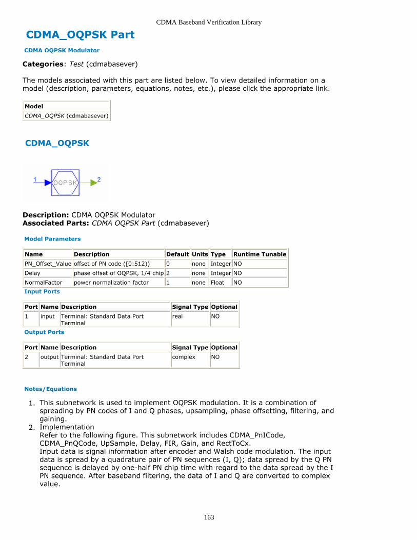
CDMA Baseband Verification Library
163
CDMA_OQPSK Part CDMA OQPSK Modulator
Categories: Test (cdmabasever)
The models associated with this part are listed below. To view detailed information on amodel (description, parameters, equations, notes, etc.), please click the appropriate link.
Model
CDMA_OQPSK (cdmabasever)
CDMA_OQPSK
Description: CDMA OQPSK ModulatorAssociated Parts: CDMA OQPSK Part (cdmabasever)
Model Parameters
Name Description Default Units Type Runtime Tunable
PN_Offset_Value offset of PN code ([0:512)) 0 none Integer NO
Delay phase offset of OQPSK, 1/4 chip 2 none Integer NO
NormalFactor power normalization factor 1 none Float NO
Input Ports
Port Name Description Signal Type Optional
1 input Terminal: Standard Data PortTerminal
real NO
Output Ports
Port Name Description Signal Type Optional
2 output Terminal: Standard Data PortTerminal
complex NO
Notes/Equations
This subnetwork is used to implement OQPSK modulation. It is a combination of1.spreading by PN codes of I and Q phases, upsampling, phase offsetting, filtering, andgaining.Implementation2.Refer to the following figure. This subnetwork includes CDMA_PnICode,CDMA_PnQCode, UpSample, Delay, FIR, Gain, and RectToCx.Input data is signal information after encoder and Walsh code modulation. The inputdata is spread by a quadrature pair of PN sequences (I, Q); data spread by the Q PNsequence is delayed by one-half PN chip time with regard to the data spread by the IPN sequence. After baseband filtering, the data of I and Q are converted to complexvalue.
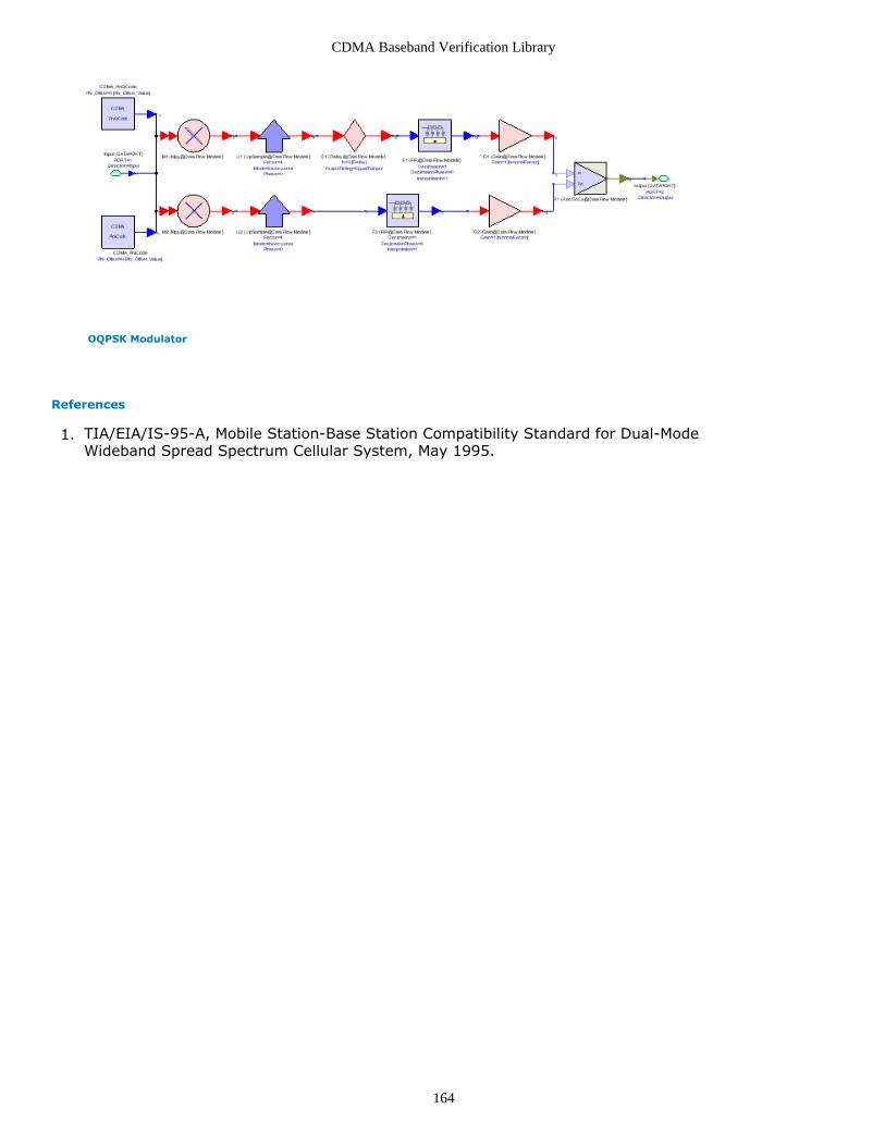
CDMA Baseband Verification Library
164
OQPSK Modulator
References
TIA/EIA/IS-95-A, Mobile Station-Base Station Compatibility Standard for Dual-Mode1.Wideband Spread Spectrum Cellular System, May 1995.

CDMA Baseband Verification Library
165
CDMA_PN_Code Part Generating In-Phase and Quadrature Phase PN Code for Despreading
Categories: Test (cdmabasever)
The models associated with this part are listed below. To view detailed information on amodel (description, parameters, equations, notes, etc.), please click the appropriate link.
Model
CDMA_PN_Code (cdmabasever)
CDMA_PN_Code
Description: Generating In-Phase and Quadrature Phase PN Code for DespreadingAssociated Parts: CDMA PN Code Part (cdmabasever)
Model Parameters
Name Description Default Units Type RuntimeTunable
PN_Offset_Value base station PN code offset ([0:512)) 0 none Integer NO
LongCodeMask1 first 16 bits of serial number for long codegenerator ([0:65535])
0 none Integer NO
LongCodeMask2 last 16 bits of serial number for long codegenerator ([0:65535])
0 none Integer NO
Output Ports
Port Name Description Signal Type Optional
1 output1 Terminal: Standard Data PortTerminal
real NO
2 output2 Terminal: Standard Data PortTerminal
real NO
Notes/Equations
This subnetwork is used to generate PN code for despreading a reverse link. It1.combines long code and quadrature spreading PN code generating process as shownin the following figure. CDMA_PnICode, CDMA_PnQCode, andCDMA_LongCodeGenerator are used; refer to these components for more details.Implementation2.After NRZ transformation, the long code is multiplied by I- and Q-path PN code andoutput for the respective paths.

CDMA Baseband Verification Library
166
References
TIA/EIA/IS-95-A, Mobile Station-Base Station Compatibility Standard for Dual-Mode1.Wideband Spread Spectrum Cellular System, May 1995.

CDMA Baseband Verification Library
167
CDMA_Sounder_Statistic PartCategories: Test (cdmabasever)
The models associated with this part are listed below. To view detailed information on amodel (description, parameters, equations, notes, etc.), please click the appropriate link.
Model Description
CDMA_Sounder_Statistic (cdmabasever) Estimation of Probability for Channel SounderOutput
CDMA_Sounder_Statistic
Description: Estimation of Probability for Channel Sounder OutputDomain: UntimedC++ Code Generation Support: NOAssociated Parts: CDMA Sounder Statistic Part (cdmabasever)
Model Parameters
Name Description Default Units Type RuntimeTunable
Range
Ini number of ineffective firings to beignored
1 Integer NO [0:∞)
Thresholds quantization thresholds, in increasingorder
0.0 Floating pointarray
NO (-∞:∞)
Levels output levels [] Floating pointarray
NO
Input Ports
Port Name Signal Type Optional
1 input real NO
Output Ports
Port Name Signal Type Optional
2 output real NO
3 Statistic int NO
Notes/Equations
This component is used to estimate the number of inputs for each level in order to1.provide input probability statistics. Frequency error is caused by Doppler effect orlocal oscillator inaccuracy.Each firing, 1 output token and N +1 statistic tokens are produced for 1 input tokenconsumed, where N equals the array size of Thresholds.Implementation2.This component is based on the Quant component (in the ADS Numeric SpecialFunctions library) to quantize the input value to N +1 possible output levels using NThresholds. It adds one output statistic to record the result of statistics (the numberof points that fall in every level) and adds one Ini parameter to count the

CDMA Baseband Verification Library
168
noneffective points.For input ≤ n th threshold, but > all previous thresholds, the output will be the nth level.For input > all thresholds, the output is the N+1 th level.For input < all thresholds, then the output is the 0 th level.The default value for level is 0, 1, 2, ... N. This star takes on the order of log Nsteps to find the correct level.

CDMA Baseband Verification Library
169
CDMA_TimeAverage PartCategories: Test (cdmabasever)
The models associated with this part are listed below. To view detailed information on amodel (description, parameters, equations, notes, etc.), please click the appropriate link.
Model Description
CDMA_TimeAverage(cdmabasever)
Average in Time Domain. This module add the input with the previous valueand average it.
CDMA_TimeAverage
Description: Average in Time Domain. This module add the input with the previous valueand average it.Domain: UntimedC++ Code Generation Support: NOAssociated Parts: CDMA TimeAverage Part (cdmabasever)
Model Parameters
Name Description Default Units Type Runtime Tunable Range
TestLength number of frames for BER estimate 10000 Integer NO [1:∞)
DotNumber number of dots needed to draw BER curve. 8 Integer NO [1:∞)
IniLength number of ineffective firings to be ignored 0 Integer NO [0:∞)
Input Ports
Port Name Description Signal Type Optional
1 input The inputdatum.
real NO
Output Ports
Port Name Description Signal Type Optional
2 output The time averageddatum.
real NO
Notes/Equations
This component is used to average the input data and avoid the multirate.1.One output token is produced when one input token is consumed.

CDMA Baseband Verification Library
170
CDMA_TrfER Part Estimating Traffic Channel Bit Error
Categories: Test (cdmabasever)
The models associated with this part are listed below. To view detailed information on amodel (description, parameters, equations, notes, etc.), please click the appropriate link.
Model
CDMA_TrfER (cdmabasever)
CDMA_TrfER
Description: Estimating Traffic Channel Bit ErrorAssociated Parts: CDMA TrfER Part (cdmabasever)
Model Parameters
Name Description Default Units Type Runtime Tunable
InitialFrame number of frames to be ignored ([0:inf)) 0 none Float NO
Input Ports
Port Name Description Signal Type Optional
1 input1 Terminal: Standard Data PortTerminal
int NO
2 rate1 Terminal: Standard Data PortTerminal
int NO
3 input2 Terminal: Standard Data PortTerminal
int NO
4 rate2 Terminal: Standard Data PortTerminal
int NO
Output Ports
Port Name Description Signal Type Optional
5 RDER Terminal: Standard Data PortTerminal
int NO
6 FEROut Terminal: Standard Data PortTerminal
int NO
7 BEROut Terminal: Standard Data PortTerminal
real NO
Notes/Equations
This component is used to estimate the BER, FER and error data rate in CDMA traffic1.channel.Refer to the following figure. This subnetwork includes CDMA_TriffERR and Delay.2.Delay sets the initial frame of input data. In the CDMA library, the 9600 bps framelength of CDMA source is 171.

CDMA Baseband Verification Library
171
CDMA_TrfER Subnetwork

CDMA Baseband Verification Library
172
CDMA_TriffERR PartCategories: Test (cdmabasever)
The models associated with this part are listed below. To view detailed information on amodel (description, parameters, equations, notes, etc.), please click the appropriate link.
Model Description
CDMA_TriffERR (cdmabasever) Estimating the Rate-Decision Error of the forward Traffic Channel.
CDMA_TriffERR
Description: Estimating the Rate-Decision Error of the forward Traffic Channel.Domain: UntimedC++ Code Generation Support: NOAssociated Parts: CDMA TriffERR Part (cdmabasever)
Model Parameters
Name Description Default Units Type Runtime Tunable Range
InitialFrame number of frames to beignored
0 Integer NO [1:∞)
Input Ports
Port Name Description Signal Type Optional
1 Input1 the input blockone.
int NO
2 rate1 the input blockone.
int NO
3 Input2 the input block two. int NO
4 rate2 the input block two. int NO
Output Ports
Port Name Description Signal Type Optional
5 RDER specify if it is a error rate-decision. int NO
6 FEROut specify if it is a error frame. int NO
7 BEROut the bit error rate. real NO
Notes/Equations
This component is used to estimate the BER, FER and decision error rate of data rate1.in CDMA traffic channel. One output token is produced when L input sink and sourcetokens are consumed.
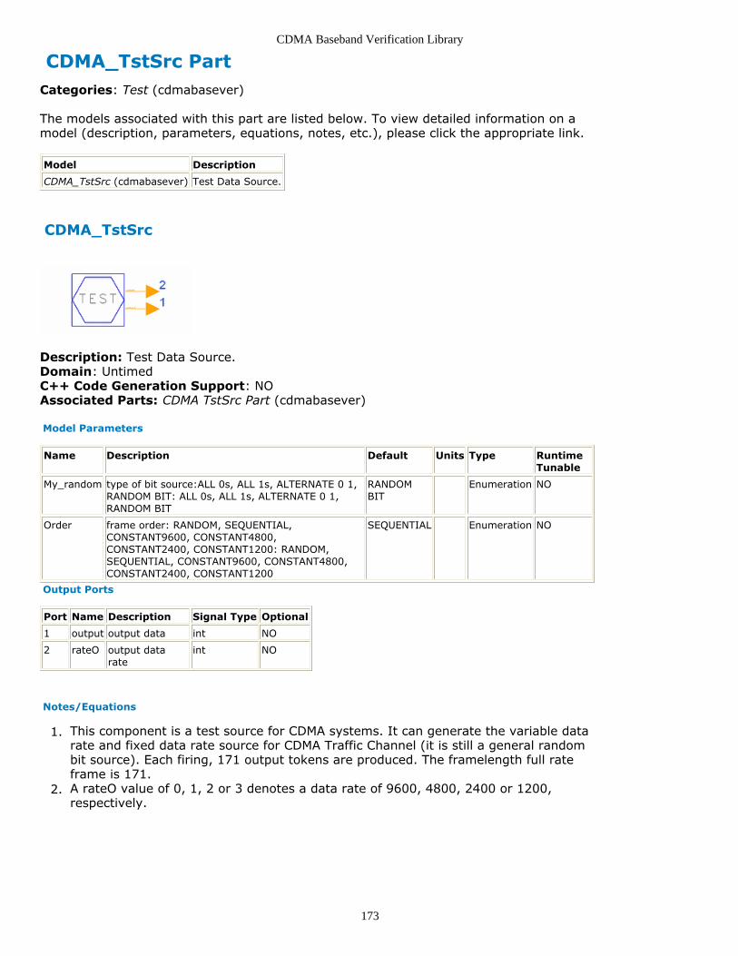
CDMA Baseband Verification Library
173
CDMA_TstSrc PartCategories: Test (cdmabasever)
The models associated with this part are listed below. To view detailed information on amodel (description, parameters, equations, notes, etc.), please click the appropriate link.
Model Description
CDMA_TstSrc (cdmabasever) Test Data Source.
CDMA_TstSrc
Description: Test Data Source.Domain: UntimedC++ Code Generation Support: NOAssociated Parts: CDMA TstSrc Part (cdmabasever)
Model Parameters
Name Description Default Units Type RuntimeTunable
My_random type of bit source:ALL 0s, ALL 1s, ALTERNATE 0 1,RANDOM BIT: ALL 0s, ALL 1s, ALTERNATE 0 1,RANDOM BIT
RANDOMBIT
Enumeration NO
Order frame order: RANDOM, SEQUENTIAL,CONSTANT9600, CONSTANT4800,CONSTANT2400, CONSTANT1200: RANDOM,SEQUENTIAL, CONSTANT9600, CONSTANT4800,CONSTANT2400, CONSTANT1200
SEQUENTIAL Enumeration NO
Output Ports
Port Name Description Signal Type Optional
1 output output data int NO
2 rateO output datarate
int NO
Notes/Equations
This component is a test source for CDMA systems. It can generate the variable data1.rate and fixed data rate source for CDMA Traffic Channel (it is still a general randombit source). Each firing, 171 output tokens are produced. The framelength full rateframe is 171.A rateO value of 0, 1, 2 or 3 denotes a data rate of 9600, 4800, 2400 or 1200,2.respectively.

CDMA Baseband Verification Library
174
CDMA Transmission Category Contents
CDMA BSTX Part (cdmabasever)CDMA DataRandomizer Part (cdmabasever)CDMA LongCodeGenerator Part (cdmabasever)CDMA M aryModulator Part (cdmabasever)CDMA MSTX Part (cdmabasever)CDMA MUX Part (cdmabasever)CDMA PCBitExtraction Part (cdmabasever)CDMA PnICode Part (cdmabasever)CDMA PnQCode Part (cdmabasever)CDMA PowerAllocation Part (cdmabasever)CDMA ReversePowerControl Part (cdmabasever)CDMA WalshModulator Part (cdmabasever)

CDMA Baseband Verification Library
175
CDMA_BSTX PartCategories: Transmission (cdmabasever)
The models associated with this part are listed below. To view detailed information on amodel (description, parameters, equations, notes, etc.), please click the appropriate link.
Model Description
CDMA_BSTX (cdmabasever) Base Station Transmitter
CDMA_BSTX
Description: Base Station TransmitterDomain: UntimedC++ Code Generation Support: NOAssociated Parts: CDMA BSTX Part (cdmabasever)
Model Parameters
Name Description Default Units Type RuntimeTunable
Range
BS_Power base station transmission power 10.0 W Float NO [0:∞)
BlockLength number of chips for each control group 24 Integer NO [1:∞)
SignalType type of input signal: BaseBand,IntermidiateFrequency
BaseBand Enumeration NO
Input Ports
Port Name Description Signal Type Optional
1 DataIn combined information chips complex NO
Output Ports
Port Name Description Signal Type Optional
2 DatOut transmission data complex NO
Notes/Equations
This component is used to allocate power for transmission data. Each firing, one1.token is produced and one token is consumed.Implementation2.Multiply an amplitude value to the normalized baseband signal, where amplitude isthe square root of transmission power. Maximum base station power is 4.0W.
References
TIA/EIA/IS-97, Recommended Minimum Performance Standards for Base Station1.Supporting Dual-Mode Wideband Spread Spectrum Cellular Mobile Station, Dec.1994, page 3-3.

CDMA Baseband Verification Library
176
CDMA_DataRandomizer PartCategories: Transmission (cdmabasever)
The models associated with this part are listed below. To view detailed information on amodel (description, parameters, equations, notes, etc.), please click the appropriate link.
Model Description
CDMA_DataRandomizer (cdmabasever) Data Burst Randomizer and Long Code Spreader for Forward Link
CDMA_DataRandomizer
Description: Data Burst Randomizer and Long Code Spreader for Forward LinkDomain: UntimedC++ Code Generation Support: NOAssociated Parts: CDMA DataRandomizer Part (cdmabasever)
Input Ports
Port Name Description Signal Type Optional
1 DtRate base band data rate int NO
2 DataIn data after M_ary modulation real NO
3 LgCode Long Code int NO
Output Ports
Port Name Description Signal Type Optional
4 DataOut data after randomizing and spreadapectrum
real NO
Notes/Equations
This component is used to puncture bits of the reverse traffic channel to decrease1.output power, then long code spread the output data. Block length will be one frame.Each firing, 6144 DataIn, 1 DtRate, and 24576 LgCode tokens are consumed and24576 DataOut tokens are produced.Implementation2.A masking pattern of 0s and 1s is generated that randomly masks out the redundantdata generated by code repetition. The masking pattern is determined by DtRate and14 bits of LgCode. These 14 bits will be the last 14 bits of the Long code used forspreading in the previous to the last power control group of the previous frame; theyare denoted as:
b0,b1,b2,b3,b4,b5,b6,b7,b8,b9,b10,b11,b12,b13
One frame can be divided into 16 power control groups 0 through 15 (one powercontrol group consists of 24 bits); the transmission will occur on power controlgroups numbered:Spread Spectrum is also implemented by multiplying long code (1-bit multiples of 4-bit Long Code).

CDMA Baseband Verification Library
177
Refer to [1].Long code is used to spread the output data; process gain is 4.
References
TIA/EIA/IS-95-A, Mobile Station-Base Station Compatibility Standard for Dual-Mode1.Wideband Spread Spectrum Cellular System, May 1995, pp. 6-19 to 6-22.
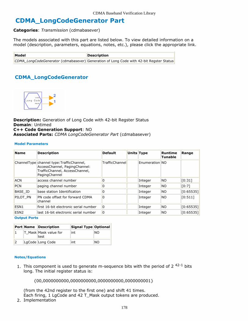
CDMA Baseband Verification Library
178
CDMA_LongCodeGenerator PartCategories: Transmission (cdmabasever)
The models associated with this part are listed below. To view detailed information on amodel (description, parameters, equations, notes, etc.), please click the appropriate link.
Model Description
CDMA_LongCodeGenerator (cdmabasever) Generation of Long Code with 42-bit Regster Status
CDMA_LongCodeGenerator
Description: Generation of Long Code with 42-bit Regster StatusDomain: UntimedC++ Code Generation Support: NOAssociated Parts: CDMA LongCodeGenerator Part (cdmabasever)
Model Parameters
Name Description Default Units Type RuntimeTunable
Range
ChannelType channel type:TrafficChannel,AccessChannel, PagingChannel:TrafficChannel, AccessChannel,PagingChannel
TrafficChannel Enumeration NO
ACN access channel number 0 Integer NO [0:31]
PCN paging channel number 0 Integer NO [0:7]
BASE_ID base station Identification 0 Integer NO [0:65535]
PILOT_PN PN code offset for forward CDMAchannel
0 Integer NO [0:511]
ESN1 first 16-bit electronic serial number 0 Integer NO [0:65535]
ESN2 last 16-bit electronic serial number 0 Integer NO [0:65535]
Output Ports
Port Name Description Signal Type Optional
1 T_Mask Mask value fortest
int NO
2 LgCode Long Code int NO
Notes/Equations
This component is used to generate m-sequence bits with the period of 2 42-1 bits1.long. The initial register status is:
{00,0000000000,0000000000,0000000000,0000000001}
(from the 42nd register to the first one) and shift 41 times.Each firing, 1 LgCode and 42 T_Mask output tokens are produced.Implementation2.

CDMA Baseband Verification Library
179
The long code period will be 2 42-1 chips and will satisfy the linear recursion specifiedby the characteristic polynomial:
There are three kinds of masks in IS-95A. Each PN chip of the long code will begenerated by the modulo-2 inner product of a 42-bit mask and the 42-bit statevector of the sequence generator (refer to [1] page 6-23).Access Channel Long Code Mask
Traffic Channel Long Code MaskWhen transmitting on the Reverse Traffic Channel, the mobile station uses a publiclong code mask:
where
ESN = (E31,E30,E29,......E2, E1, E0)permuted ESN = (E0, E31, E22, E13, E4, E26, E17, E8, E30, E21, E12, E3,E25, E16, E7, E29, E20, E2, E24, E15, E6, E28, E19, E10, E1, E23, E14, E5,E27, E18, E9)
refer to [1] page 6-24.Paging Channel Long Code Mask
refer to [1] page 7-27.In this component, the binary number must be converted to two 7-place octal Masksand add one 0 before each mask.
References
TIA/EIA/IS-95-A, Mobile Station-Base Station Compatibility Standard for Dual-Mode1.Wideband Spread Spectrum Cellular System, May 1995.

CDMA Baseband Verification Library
180
CDMA_M_aryModulator PartCategories: Transmission (cdmabasever)
The models associated with this part are listed below. To view detailed information on amodel (description, parameters, equations, notes, etc.), please click the appropriate link.
Model Description
CDMA_M_aryModulator (cdmabasever) M-ary Modulator for Non-CoherentDetection
CDMA_M_aryModulator
Description: M-ary Modulator for Non-Coherent DetectionDomain: UntimedC++ Code Generation Support: NOAssociated Parts: CDMA M aryModulator Part (cdmabasever)
Input Ports
Port Name Description Signal Type Optional
1 DataIn the input data bit to be modulated real NO
Output Ports
Port Name Description Signal Type Optional
2 SymOut the data chip after M_ary modulation real NO
Notes/Equations
This component is used to convert 6-bit information sequence to 1 Walsh code (641.chips).Each firing 6 DataIn tokens are consumed; 64 SymOut 64 tokens are produced.Implementation2.The 6-bit information sequence is converted to one decimal number that is used asthe Walsh code index. The 6-bit information is then replaced by one Walsh symbol.The n th chip of the m th Walsh symbol W[n] is derived from:
W[n]={m[5](and)n[5]} xor {m[5](and)n[5]} .... xor {m[0](and)n[0]}
where, m[5] ~ m[0] is the input data, n is the n th output data, which is convertedfrom decimal to binary.

CDMA Baseband Verification Library
181
CDMA_MSTX PartCategories: Transmission (cdmabasever)
The models associated with this part are listed below. To view detailed information on amodel (description, parameters, equations, notes, etc.), please click the appropriate link.
Model Description
CDMA_MSTX (cdmabasever) Mobile StationTransmitter
CDMA_MSTX
Description: Mobile Station TransmitterDomain: UntimedC++ Code Generation Support: NOAssociated Parts: CDMA MSTX Part (cdmabasever)
Model Parameters
Name Description Default Units Type RuntimeTunable
Range
PowerControl enable the Power Control: Yes, No: Yes, No Yes Enumeration NO
MS_Power mobile station maximum output power 4.0 W Float NO [0:∞)
Init_Power mobile station initial transmission power 1.0 W Float NO [0:∞)
PowerStep Mobile Station power adjustmnet step, unit:dB
1.0 Float NO (-∞:∞)
BlockLength number of chips for each power controlgroup
24 Integer NO [1:∞)
SignalType type of input signal:BaseBand,IntermediateFrequency: BaseBand,IntermidiateFrequency
BaseBand Enumeration NO
Input Ports
Port Name Description Signal Type Optional
1 DataIn MS TrafficChannel
complex NO
2 PCBit Power Control Bit int NO
Output Ports
Port Name Description Signal Type Optional
3 DataOut Transmission Data complex NO
Notes/Equations
This component is used to allocate real transmission for the mobile station and adjust1.output power according to the power control bit.Each firing, DataIn consumes BlockLength tokens, PCBit consumes 1 token, and2.DataOut produces BlockLength tokens.

CDMA Baseband Verification Library
182
Implementation3.It is equal to assign amplitude for the normalized baseband signal, the amplitude isthe power.Then if the power control bit is 0 the mobile station will increase its power at aPowerStep value; otherwise, the mobile station will decrease its power at aPowerStep value.
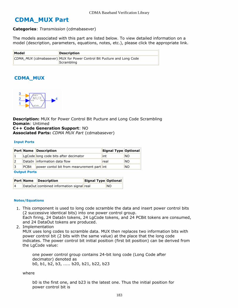
CDMA Baseband Verification Library
183
CDMA_MUX PartCategories: Transmission (cdmabasever)
The models associated with this part are listed below. To view detailed information on amodel (description, parameters, equations, notes, etc.), please click the appropriate link.
Model Description
CDMA_MUX (cdmabasever) MUX for Power Control Bit Pucture and Long CodeScrambling
CDMA_MUX
Description: MUX for Power Control Bit Pucture and Long Code ScramblingDomain: UntimedC++ Code Generation Support: NOAssociated Parts: CDMA MUX Part (cdmabasever)
Input Ports
Port Name Description Signal Type Optional
1 LgCode long code bits after decimator int NO
2 DataIn information data flow real NO
3 PCBit power contol bit from mearurement part int NO
Output Ports
Port Name Description Signal Type Optional
4 DataOut combined information signal real NO
Notes/Equations
This component is used to long code scramble the data and insert power control bits1.(2 successive identical bits) into one power control group.Each firing, 24 DataIn tokens, 24 LgCode tokens, and 24 PCBit tokens are consumed,and 24 DataOut tokens are produced.Implementation2.MUX uses long codes to scramble data. MUX then replaces two information bits withpower control bit (2 bits with the same value) at the place that the long codeindicates. The power control bit initial position (first bit position) can be derived fromthe LgCode value:
one power control group contains 24-bit long code (Long Code afterdecimator) denoted asb0, b1, b2, b3, ..... b20, b21, b22, b23
where
b0 is the first one, and b23 is the latest one. Thus the initial position forpower control bit is

CDMA Baseband Verification Library
184
position= 23 ×b23+22 ×b22+2×b21+b20
Refer to [1].
References
TIA/EIA/IS-95-A, Mobile Station-Base Station Compatibility Standard for Dual-Mode1.Wideband Spread Spectrum Cellular System, May 1995.

CDMA Baseband Verification Library
185
CDMA_PCBitExtraction PartCategories: Transmission (cdmabasever)
The models associated with this part are listed below. To view detailed information on amodel (description, parameters, equations, notes, etc.), please click the appropriate link.
Model Description
CDMA_PCBitExtraction (cdmabasever) Extract Power Control Bit and DescrambleData
CDMA_PCBitExtraction
Description: Extract Power Control Bit and Descramble DataDomain: UntimedC++ Code Generation Support: NOAssociated Parts: CDMA PCBitExtraction Part (cdmabasever)
Input Ports
Port Name Description Signal Type Optional
1 DataIn input data real NO
2 LgCode long code int NO
Output Ports
Port Name Description Signal Type Optional
3 PCBit power control bit int NO
4 DatOut data after extracting and de-scrambling real NO
Notes/Equations
This component is used to extract the power control bit from decoded traffic bits,1.replace it with 0, and use long code to de-scramble the data. This componentprocesses one power control group as a block (24 bits).Each firing 24 DataIn tokens and 24 LgCode tokens are consumed, and 1 PCBit tokenand 24 DataOut tokens are produced.Implementation2.This component extracts the power control bit at every power control group andsends it to the mobile station power controller; it replaces the power control bits (2successive identical bits) with 0. Two analogy values will be combined into one powercontrol integer bit.The power control bit initial position (first bit position) can be derived from theLgCode value:
one power control group contains 24-bit long codes (Long Code afterdeciminator) denoted as:b0, b1, b2, b3, ... , b20, b21, b22, b23
where

CDMA Baseband Verification Library
186
b0 is the first one, and b23 is the latest one.
Thus the initial position for power control bit is:
position= 23 ×b23+22 ×b22+2×b21+b20
It then uses long codes to descramble the data.
References
TIA/EIA/IS-95-A, Mobile Station-Base Station Compatibility Standard for Dual-Mode1.Wideband Spread Spectrum Cellular System, May 1995.
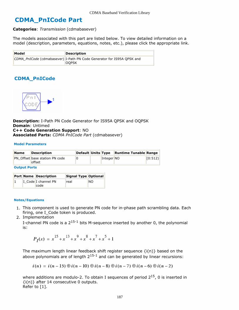
CDMA Baseband Verification Library
187
CDMA_PnICode PartCategories: Transmission (cdmabasever)
The models associated with this part are listed below. To view detailed information on amodel (description, parameters, equations, notes, etc.), please click the appropriate link.
Model Description
CDMA_PnICode (cdmabasever) I-Path PN Code Generator for IS95A QPSK andOQPSK
CDMA_PnICode
Description: I-Path PN Code Generator for IS95A QPSK and OQPSKDomain: UntimedC++ Code Generation Support: NOAssociated Parts: CDMA PnICode Part (cdmabasever)
Model Parameters
Name Description Default Units Type Runtime Tunable Range
PN_Offset base station PN codeoffset
0 Integer NO [0:512)
Output Ports
Port Name Description Signal Type Optional
1 I_Code I channel PNcode
real NO
Notes/Equations
This component is used to generate PN code for in-phase path scrambling data. Each1.firing, one I_Code token is produced.Implementation2.I-channel PN code is a 215-1 bits M-sequence inserted by another 0, the polynomialis:
The maximum length linear feedback shift register sequence {i(n)} based on theabove polynomials are of length 215-1 and can be generated by linear recursions:
where additions are modulo-2. To obtain I sequences of period 215, 0 is inserted in{i(n)} after 14 consecutive 0 outputs.Refer to [1].

CDMA Baseband Verification Library
188
References
TIA/EIA/IS-95-A, Mobile Station-Base Station Compatibility Standard for Dual-Mode1.Wideband Spread Spectrum Cellular System, May 1995, p 7-18.

CDMA Baseband Verification Library
189
CDMA_PnQCode PartCategories: Transmission (cdmabasever)
The models associated with this part are listed below. To view detailed information on amodel (description, parameters, equations, notes, etc.), please click the appropriate link.
Model Description
CDMA_PnQCode (cdmabasever) Q-Path PN Code Generator for IS95A QPSK andOQPSK
CDMA_PnQCode
Description: Q-Path PN Code Generator for IS95A QPSK and OQPSKDomain: UntimedC++ Code Generation Support: NOAssociated Parts: CDMA PnQCode Part (cdmabasever)
Model Parameters
Name Description Default Units Type Runtime Tunable Range
PN_Offset base station PN codeoffset
0 Integer NO [0:512)
Output Ports
Port Name Description Signal Type Optional
1 Q_Code Q channel PN code real NO
Notes/Equations
This component is used to generate PN code for quadrature path scrambling data.1.Each firing, 1 Q_Code token is produced.Implementation2.Q-channel PN code is a 215-1 -bit M-sequence inserted by another 0, the polynomialis:
The maximum length linear feedback shift register sequence {q(n)} based on theabove polynomials are 215-1 and can be generated by linear recursions:
where additions are modulo-2.To obtain the I sequences of period 215, 0 is inserted in {q(n)} after 14 consecutive0 outputs.

CDMA Baseband Verification Library
190
References
TIA/EIA/IS-95-A, Mobile Station-Base Station Compatibility Standard for Dual-Mode1.Wideband Spread Spectrum Cellular System, May 1995, page 7-18.

CDMA Baseband Verification Library
191
CDMA_PowerAllocation PartCategories: Transmission (cdmabasever)
The models associated with this part are listed below. To view detailed information on amodel (description, parameters, equations, notes, etc.), please click the appropriate link.
Model Description
CDMA_PowerAllocation (cdmabasever) Power Allocation for Different Base StationChannel
CDMA_PowerAllocation
Description: Power Allocation for Different Base Station ChannelDomain: UntimedC++ Code Generation Support: NOAssociated Parts: CDMA PowerAllocation Part (cdmabasever)
Model Parameters
Name Description Default Units Type RuntimeTunable
Range
PilotPowerRatio ratio of pilot channel power to total power 0.2 Float NO [0:1)
SyncRelativeDB sync channel power relative to one trafficchannel power, in dB
-3.0 Float NO (-∞:∞)
PagingRelativeDB paging channel power relative to one trafficchannel power, in dB
3.0 Float NO (-∞:∞)
Input Ports
Port Name Description Signal Type Optional
1 Pilot Pilot Channel Data real NO
2 Sync Sync Channel Data real NO
3 Paging Paging Channel Data real NO
4 TrData multi user data multiple real NO
Output Ports
Port Name Description Signal Type Optional
5 DatOut output data real NO
Notes/Equations
This component is used to allocate power for the forward transmission link (including1.pilot channel, sync channel, paging channel, and three forward traffic channels).The traffic channel data is multiple input; connected traffic users can automatically bedetected and corresponding parts calculated.Each firing, BlockLength output tokens are consumed and BlockLength tokens areproduced.Implementation2.Assume each traffic channel has the same power and

CDMA Baseband Verification Library
192

CDMA Baseband Verification Library
193
CDMA_ReversePowerControl PartCategories: Transmission (cdmabasever)
The models associated with this part are listed below. To view detailed information on amodel (description, parameters, equations, notes, etc.), please click the appropriate link.
Model Description
CDMA_ReversePowerControl (cdmabasever) Reverse Power Control for Base to MobileTransmission
CDMA_ReversePowerControl
Description: Reverse Power Control for Base to Mobile TransmissionDomain: UntimedC++ Code Generation Support: NOAssociated Parts: CDMA ReversePowerControl Part (cdmabasever)
Model Parameters
Name Description Default Units Type RuntimeTunable
Range
SIR_Threshold minimum signal-to-interference ratio 4.5 Float NO [0:∞)
SIR_AdjustStep signal-to-interference ratio adjustment step 0.2 Float NO (-∞:∞)
FER_Threshold threshold of frame error rate: if detected FER>the threshold, transmission power increased,and vice versa
0.01 Float NO [0:1]
Input Ports
Port Name Description Signal Type Optional
1 Eb bit energy real NO
2 I interference real NO
3 Rate If Rate=5 or 6, it is a bad Frame int NO
Output Ports
Port Name Description Signal Type Optional
4 PCBit Power ControlBit
int NO
Notes/Equations
This component is used to control base station transmission power to the mobile1.station to overcome the near-far effect and increase system capacity.Each firing, 1 token is consumed for each input and one token is produced for theoutput.Implementation2.Refer to the following figure.

CDMA Baseband Verification Library
194
CDMA_ReversePowerControl Block Diagram
SIR_Measure is used to calculate the signal-to-interference ratio (SIR) for the Eb andI inputs:
FER_Measure is used to calculate the frame error rate (FER). CRC determineswhether or not a frame is good.
FER= number of good frames / number of total frames
Since high-rate frames (9600 bps or 4800 bps) have CRC, low rate frames (2400 bpsand 1200 bps) are considered good. If the full rate frame is not good, the rate will be5 to indicate an error frame; if the half rate frame is not good, the rate will be 6 toindicate an error frame.SIR_Threshold_Adjust is used to calculate the actual SIR and adjust the SIRthreshold according to the environmental requirement. If FER > FER_Min, the SIRthreshold will be increased, otherwise it will be decreased. The new SIR thresholdcannot be < SIR_Min.Decision is used to compare the two current SIR and required SIR_Min.Power_Control_Bit sets PCBit. If the current SIR > required SIR_Min, the output isset to 0, otherwise it is set to 1. Power_Control_Bit will be repeated, so thePower_Control_Bit will be 2 repeated bit values.

CDMA Baseband Verification Library
195
CDMA_WalshModulator PartCategories: Transmission (cdmabasever)
The models associated with this part are listed below. To view detailed information on amodel (description, parameters, equations, notes, etc.), please click the appropriate link.
Model Description
CDMA_WalshModulator (cdmabasever) Walsh Modulator for 64-BitSpread
CDMA_WalshModulator
Description: Walsh Modulator for 64-Bit SpreadDomain: UntimedC++ Code Generation Support: NOAssociated Parts: CDMA WalshModulator Part (cdmabasever)
Model Parameters
Name Description Default Units Type Runtime Tunable Range
WalshCodeIndex Walsh code index 0 Integer NO [0:63]
Input Ports
Port Name Description Signal Type Optional
1 DataIn the input data bit to be modulated real NO
Output Ports
Port Name Description Signal Type Optional
2 SymOut the data chip after Walsh modulation real NO
Notes/Equations
This component is used to generate 64-bit long Walsh symbols (0 ~ 63, each symbol1.has 64 bits) and spread one input data from forward channels with one Walsh symbolto 64 bits. Each firing, 1 DataIn token is consumed and 64 SymOut tokens areproduced.Implementation2.The n th chip of the m th Walsh symbol W[m][n] is derived from
W[m][n]={m[5](and)n[5]} xor {m[5](and)n[5]} .... xor {m[0](and)n[0]}
where, array m, n is a 6-dimension binary-number array that is converted fromdecimal number m, n.Walsh symbol (convert to bi-polar code) is used to multiply the input data, and oneinput data is spread. The process gain is 64.