isdbt baseband verification library -...
TRANSCRIPT

SystemVue - ISDBT Baseband Verification Library
1
SystemVue 2011.032011
ISDBT Baseband Verification Library
This is the default Notice page
SystemVue - ISDBT Baseband Verification Library
2
© Agilent Technologies, Inc. 2000-2010395 Page Mill Road, Palo Alto, CA 94304 U.S.A.No part of this manual may be reproduced in any form or by any means (includingelectronic storage and retrieval or translation into a foreign language) without prioragreement and written consent from Agilent Technologies, Inc. as governed by UnitedStates and international copyright laws.
Acknowledgments Mentor Graphics is a trademark of Mentor Graphics Corporation inthe U.S. and other countries. Microsoft®, Windows®, MS Windows®, Windows NT®, andMS-DOS® are U.S. registered trademarks of Microsoft Corporation. Pentium® is a U.S.registered trademark of Intel Corporation. PostScript® and Acrobat® are trademarks ofAdobe Systems Incorporated. UNIX® is a registered trademark of the Open Group. Java™is a U.S. trademark of Sun Microsystems, Inc. SystemC® is a registered trademark ofOpen SystemC Initiative, Inc. in the United States and other countries and is used withpermission. MATLAB® is a U.S. registered trademark of The Math Works, Inc.. HiSIM2source code, and all copyrights, trade secrets or other intellectual property rights in and tothe source code in its entirety, is owned by Hiroshima University and STARC.
Errata The SystemVue product may contain references to "HP" or "HPEESOF" such as infile names and directory names. The business entity formerly known as "HP EEsof" is nowpart of Agilent Technologies and is known as "Agilent EEsof". To avoid broken functionalityand to maintain backward compatibility for our customers, we did not change all thenames and labels that contain "HP" or "HPEESOF" references.
Warranty The material contained in this document is provided "as is", and is subject tobeing changed, without notice, in future editions. Further, to the maximum extentpermitted by applicable law, Agilent disclaims all warranties, either express or implied,with regard to this manual and any information contained herein, including but not limitedto the implied warranties of merchantability and fitness for a particular purpose. Agilentshall not be liable for errors or for incidental or consequential damages in connection withthe furnishing, use, or performance of this document or of any information containedherein. Should Agilent and the user have a separate written agreement with warrantyterms covering the material in this document that conflict with these terms, the warrantyterms in the separate agreement shall control.
Technology Licenses The hardware and/or software described in this document arefurnished under a license and may be used or copied only in accordance with the terms ofsuch license.
Portions of this product is derivative work based on the University of California PtolemySoftware System.
In no event shall the University of California be liable to any party for direct, indirect,special, incidental, or consequential damages arising out of the use of this software and itsdocumentation, even if the University of California has been advised of the possibility ofsuch damage.
The University of California specifically disclaims any warranties, including, but not limitedto, the implied warranties of merchantability and fitness for a particular purpose. Thesoftware provided hereunder is on an "as is" basis and the University of California has noobligation to provide maintenance, support, updates, enhancements, or modifications.
Portions of this product include code developed at the University of Maryland, for theseportions the following notice applies.
In no event shall the University of Maryland be liable to any party for direct, indirect,special, incidental, or consequential damages arising out of the use of this software and itsdocumentation, even if the University of Maryland has been advised of the possibility ofsuch damage.
The University of Maryland specifically disclaims any warranties, including, but not limitedto, the implied warranties of merchantability and fitness for a particular purpose. thesoftware provided hereunder is on an "as is" basis, and the University of Maryland has noobligation to provide maintenance, support, updates, enhancements, or modifications.
SystemVue - ISDBT Baseband Verification Library
3
Portions of this product include the SystemC software licensed under Open Source terms,which are available for download at http://systemc.org/ . This software is redistributed byAgilent. The Contributors of the SystemC software provide this software "as is" and offerno warranty of any kind, express or implied, including without limitation warranties orconditions or title and non-infringement, and implied warranties or conditionsmerchantability and fitness for a particular purpose. Contributors shall not be liable forany damages of any kind including without limitation direct, indirect, special, incidentaland consequential damages, such as lost profits. Any provisions that differ from thisdisclaimer are offered by Agilent only.With respect to the portion of the Licensed Materials that describes the software andprovides instructions concerning its operation and related matters, "use" includes the rightto download and print such materials solely for the purpose described above.
Restricted Rights Legend If software is for use in the performance of a U.S.Government prime contract or subcontract, Software is delivered and licensed as"Commercial computer software" as defined in DFAR 252.227-7014 (June 1995), or as a"commercial item" as defined in FAR 2.101(a) or as "Restricted computer software" asdefined in FAR 52.227-19 (June 1987) or any equivalent agency regulation or contractclause. Use, duplication or disclosure of Software is subject to Agilent Technologies´standard commercial license terms, and non-DOD Departments and Agencies of the U.S.Government will receive no greater than Restricted Rights as defined in FAR 52.227-19(c)(1-2) (June 1987). U.S. Government users will receive no greater than LimitedRights as defined in FAR 52.227-14 (June 1987) or DFAR 252.227-7015 (b)(2) (November1995), as applicable in any technical data.
SystemVue - ISDBT Baseband Verification Library
4
About ISDBT Baseband Verification Library . . . . . . . . . . . . . . . . . . . . . . . . . . . . . . . . . . . . . . 6 ISDBT Channel Coding Category . . . . . . . . . . . . . . . . . . . . . . . . . . . . . . . . . . . . . . . . . . . . . 19
Contents . . . . . . . . . . . . . . . . . . . . . . . . . . . . . . . . . . . . . . . . . . . . . . . . . . . . . . . . . . . . 19 ISDBT_CDSCDecoder Part . . . . . . . . . . . . . . . . . . . . . . . . . . . . . . . . . . . . . . . . . . . . . . . . . . 20
ISDBT_CDSCDecoder . . . . . . . . . . . . . . . . . . . . . . . . . . . . . . . . . . . . . . . . . . . . . . . . . . . . 20 ISDBT_ChCoder Part . . . . . . . . . . . . . . . . . . . . . . . . . . . . . . . . . . . . . . . . . . . . . . . . . . . . . . 21
ISDBT_ChCoder . . . . . . . . . . . . . . . . . . . . . . . . . . . . . . . . . . . . . . . . . . . . . . . . . . . . . . . 21 ISDBT_ChDecoder Part . . . . . . . . . . . . . . . . . . . . . . . . . . . . . . . . . . . . . . . . . . . . . . . . . . . . 22
ISDBT_ChDecoder . . . . . . . . . . . . . . . . . . . . . . . . . . . . . . . . . . . . . . . . . . . . . . . . . . . . . . 22 ISDBT_Derandomize Part . . . . . . . . . . . . . . . . . . . . . . . . . . . . . . . . . . . . . . . . . . . . . . . . . . 23
ISDBT_Derandomize . . . . . . . . . . . . . . . . . . . . . . . . . . . . . . . . . . . . . . . . . . . . . . . . . . . . 23 ISDBT_LFSRCoder Part . . . . . . . . . . . . . . . . . . . . . . . . . . . . . . . . . . . . . . . . . . . . . . . . . . . . 24
ISDBT_LFSRCoder . . . . . . . . . . . . . . . . . . . . . . . . . . . . . . . . . . . . . . . . . . . . . . . . . . . . . . 24 ISDBT_PNGenerator Part . . . . . . . . . . . . . . . . . . . . . . . . . . . . . . . . . . . . . . . . . . . . . . . . . . . 26
ISDBT_PNGenerator . . . . . . . . . . . . . . . . . . . . . . . . . . . . . . . . . . . . . . . . . . . . . . . . . . . . 26 ISDBT_PuncCoder Part . . . . . . . . . . . . . . . . . . . . . . . . . . . . . . . . . . . . . . . . . . . . . . . . . . . . 27
ISDBT_PuncCoder . . . . . . . . . . . . . . . . . . . . . . . . . . . . . . . . . . . . . . . . . . . . . . . . . . . . . . 27 ISDBT_PuncDecoder Part . . . . . . . . . . . . . . . . . . . . . . . . . . . . . . . . . . . . . . . . . . . . . . . . . . 28
ISDBT_PuncDecoder . . . . . . . . . . . . . . . . . . . . . . . . . . . . . . . . . . . . . . . . . . . . . . . . . . . . 28 ISDBT_Randomize Part . . . . . . . . . . . . . . . . . . . . . . . . . . . . . . . . . . . . . . . . . . . . . . . . . . . . 29
ISDBT_Randomize . . . . . . . . . . . . . . . . . . . . . . . . . . . . . . . . . . . . . . . . . . . . . . . . . . . . . . 29 ISDBT Interleaving Category . . . . . . . . . . . . . . . . . . . . . . . . . . . . . . . . . . . . . . . . . . . . . . . . 30
Contents . . . . . . . . . . . . . . . . . . . . . . . . . . . . . . . . . . . . . . . . . . . . . . . . . . . . . . . . . . . . 30 ISDBT_CarrierRotator Part . . . . . . . . . . . . . . . . . . . . . . . . . . . . . . . . . . . . . . . . . . . . . . . . . . 31
ISDBT_CarrierRotator . . . . . . . . . . . . . . . . . . . . . . . . . . . . . . . . . . . . . . . . . . . . . . . . . . . 31 ISDBT_CarrierScrambler Part . . . . . . . . . . . . . . . . . . . . . . . . . . . . . . . . . . . . . . . . . . . . . . . . 32
ISDBT_CarrierScrambler . . . . . . . . . . . . . . . . . . . . . . . . . . . . . . . . . . . . . . . . . . . . . . . . . 32 ISDBT_FreqDeinterlv Part . . . . . . . . . . . . . . . . . . . . . . . . . . . . . . . . . . . . . . . . . . . . . . . . . . 33
ISDBT_FreqDeinterlv . . . . . . . . . . . . . . . . . . . . . . . . . . . . . . . . . . . . . . . . . . . . . . . . . . . . 33 ISDBT_FreqInterlv Part . . . . . . . . . . . . . . . . . . . . . . . . . . . . . . . . . . . . . . . . . . . . . . . . . . . . 34
ISDBT_FreqInterlv . . . . . . . . . . . . . . . . . . . . . . . . . . . . . . . . . . . . . . . . . . . . . . . . . . . . . . 34 ISDBT_InterlvFloat Part . . . . . . . . . . . . . . . . . . . . . . . . . . . . . . . . . . . . . . . . . . . . . . . . . . . . 35
ISDBT_InterlvFloat . . . . . . . . . . . . . . . . . . . . . . . . . . . . . . . . . . . . . . . . . . . . . . . . . . . . . 35 ISDBT_InterlvInt Part . . . . . . . . . . . . . . . . . . . . . . . . . . . . . . . . . . . . . . . . . . . . . . . . . . . . . 36
ISDBT_InterlvInt . . . . . . . . . . . . . . . . . . . . . . . . . . . . . . . . . . . . . . . . . . . . . . . . . . . . . . . 36 ISDBT_InterSegInterlv Part . . . . . . . . . . . . . . . . . . . . . . . . . . . . . . . . . . . . . . . . . . . . . . . . . 37
ISDBT_InterSegInterlv . . . . . . . . . . . . . . . . . . . . . . . . . . . . . . . . . . . . . . . . . . . . . . . . . . . 37 ISDBT_TimeInterlvDelay Part . . . . . . . . . . . . . . . . . . . . . . . . . . . . . . . . . . . . . . . . . . . . . . . . 38
ISDBT_TimeInterlvDelay . . . . . . . . . . . . . . . . . . . . . . . . . . . . . . . . . . . . . . . . . . . . . . . . . 38 ISDBT_TimeInterlv Part . . . . . . . . . . . . . . . . . . . . . . . . . . . . . . . . . . . . . . . . . . . . . . . . . . . . 39
ISDBT_TimeInterlv . . . . . . . . . . . . . . . . . . . . . . . . . . . . . . . . . . . . . . . . . . . . . . . . . . . . . 39 ISDBT_TwoLayFreqDeinterlv Part . . . . . . . . . . . . . . . . . . . . . . . . . . . . . . . . . . . . . . . . . . . . . 40
ISDBT_TwoLayFreqDeinterlv . . . . . . . . . . . . . . . . . . . . . . . . . . . . . . . . . . . . . . . . . . . . . . . 40 ISDBT_TwoLayFreqInterlv Part . . . . . . . . . . . . . . . . . . . . . . . . . . . . . . . . . . . . . . . . . . . . . . . 42
ISDBT_TwoLayFreqInterlv . . . . . . . . . . . . . . . . . . . . . . . . . . . . . . . . . . . . . . . . . . . . . . . . 43 ISDBT Modulation Category . . . . . . . . . . . . . . . . . . . . . . . . . . . . . . . . . . . . . . . . . . . . . . . . . 44
Contents . . . . . . . . . . . . . . . . . . . . . . . . . . . . . . . . . . . . . . . . . . . . . . . . . . . . . . . . . . . . 44 ISDBT_CFRNorm Part . . . . . . . . . . . . . . . . . . . . . . . . . . . . . . . . . . . . . . . . . . . . . . . . . . . . . 45
ISDBT_CFRNorm . . . . . . . . . . . . . . . . . . . . . . . . . . . . . . . . . . . . . . . . . . . . . . . . . . . . . . . 45 ISDBT_Demapper Part . . . . . . . . . . . . . . . . . . . . . . . . . . . . . . . . . . . . . . . . . . . . . . . . . . . . 46
ISDBT_Demapper . . . . . . . . . . . . . . . . . . . . . . . . . . . . . . . . . . . . . . . . . . . . . . . . . . . . . . 46 ISDBT_Demodulation Part . . . . . . . . . . . . . . . . . . . . . . . . . . . . . . . . . . . . . . . . . . . . . . . . . . 47
ISDBT_Demodulation . . . . . . . . . . . . . . . . . . . . . . . . . . . . . . . . . . . . . . . . . . . . . . . . . . . . 47 ISDBT_DQPSKCoder Part . . . . . . . . . . . . . . . . . . . . . . . . . . . . . . . . . . . . . . . . . . . . . . . . . . . 48
ISDBT_DQPSKCoder . . . . . . . . . . . . . . . . . . . . . . . . . . . . . . . . . . . . . . . . . . . . . . . . . . . . 48 ISDBT_DQPSKDecoder Part . . . . . . . . . . . . . . . . . . . . . . . . . . . . . . . . . . . . . . . . . . . . . . . . . 49
ISDBT_DQPSKDecoder . . . . . . . . . . . . . . . . . . . . . . . . . . . . . . . . . . . . . . . . . . . . . . . . . . . 49 ISDBT_Mapper Part . . . . . . . . . . . . . . . . . . . . . . . . . . . . . . . . . . . . . . . . . . . . . . . . . . . . . . 50
ISDBT_Mapper . . . . . . . . . . . . . . . . . . . . . . . . . . . . . . . . . . . . . . . . . . . . . . . . . . . . . . . . 50 ISDBT_Modulation Part . . . . . . . . . . . . . . . . . . . . . . . . . . . . . . . . . . . . . . . . . . . . . . . . . . . . 51
ISDBT_Modulation . . . . . . . . . . . . . . . . . . . . . . . . . . . . . . . . . . . . . . . . . . . . . . . . . . . . . . 51 ISDBT_TMCCDemod Part . . . . . . . . . . . . . . . . . . . . . . . . . . . . . . . . . . . . . . . . . . . . . . . . . . . 52
ISDBT_TMCCDemod . . . . . . . . . . . . . . . . . . . . . . . . . . . . . . . . . . . . . . . . . . . . . . . . . . . . 52 ISDBT_TMCCMod Part . . . . . . . . . . . . . . . . . . . . . . . . . . . . . . . . . . . . . . . . . . . . . . . . . . . . . 53
ISDBT_TMCCMod . . . . . . . . . . . . . . . . . . . . . . . . . . . . . . . . . . . . . . . . . . . . . . . . . . . . . . 53
SystemVue - ISDBT Baseband Verification Library
5
ISDBT Multiplexing Category . . . . . . . . . . . . . . . . . . . . . . . . . . . . . . . . . . . . . . . . . . . . . . . . 54 Contents . . . . . . . . . . . . . . . . . . . . . . . . . . . . . . . . . . . . . . . . . . . . . . . . . . . . . . . . . . . . 54
ISDBT_DelayCx Part . . . . . . . . . . . . . . . . . . . . . . . . . . . . . . . . . . . . . . . . . . . . . . . . . . . . . . 55 ISDBT_DelayCx . . . . . . . . . . . . . . . . . . . . . . . . . . . . . . . . . . . . . . . . . . . . . . . . . . . . . . . . 55
ISDBT_DelayInt Part . . . . . . . . . . . . . . . . . . . . . . . . . . . . . . . . . . . . . . . . . . . . . . . . . . . . . . 56 ISDBT_DelayInt . . . . . . . . . . . . . . . . . . . . . . . . . . . . . . . . . . . . . . . . . . . . . . . . . . . . . . . 56
ISDBT_DemuxCohSegs Part . . . . . . . . . . . . . . . . . . . . . . . . . . . . . . . . . . . . . . . . . . . . . . . . . 57 ISDBT_DemuxCohSegs . . . . . . . . . . . . . . . . . . . . . . . . . . . . . . . . . . . . . . . . . . . . . . . . . . 57
ISDBT_DemuxDiffSegs Part . . . . . . . . . . . . . . . . . . . . . . . . . . . . . . . . . . . . . . . . . . . . . . . . . 58 ISDBT_DemuxDiffSegs . . . . . . . . . . . . . . . . . . . . . . . . . . . . . . . . . . . . . . . . . . . . . . . . . . . 58
ISDBT_DemuxSegs Part . . . . . . . . . . . . . . . . . . . . . . . . . . . . . . . . . . . . . . . . . . . . . . . . . . . 59 ISDBT_DemuxSegs . . . . . . . . . . . . . . . . . . . . . . . . . . . . . . . . . . . . . . . . . . . . . . . . . . . . . 59
ISDBT_MuxCohSegs Part . . . . . . . . . . . . . . . . . . . . . . . . . . . . . . . . . . . . . . . . . . . . . . . . . . . 61 ISDBT_MuxCohSegs . . . . . . . . . . . . . . . . . . . . . . . . . . . . . . . . . . . . . . . . . . . . . . . . . . . . 61
ISDBT_MuxDiffSegs Part . . . . . . . . . . . . . . . . . . . . . . . . . . . . . . . . . . . . . . . . . . . . . . . . . . . 63 ISDBT_MuxDiffSegs . . . . . . . . . . . . . . . . . . . . . . . . . . . . . . . . . . . . . . . . . . . . . . . . . . . . . 63
ISDBT_SegmentMux Part . . . . . . . . . . . . . . . . . . . . . . . . . . . . . . . . . . . . . . . . . . . . . . . . . . 64 ISDBT_SegmentMux . . . . . . . . . . . . . . . . . . . . . . . . . . . . . . . . . . . . . . . . . . . . . . . . . . . . 64
ISDBT OFDM Category . . . . . . . . . . . . . . . . . . . . . . . . . . . . . . . . . . . . . . . . . . . . . . . . . . . . 66 Contents . . . . . . . . . . . . . . . . . . . . . . . . . . . . . . . . . . . . . . . . . . . . . . . . . . . . . . . . . . . . 66
ISDBT_2DChEstimator Part . . . . . . . . . . . . . . . . . . . . . . . . . . . . . . . . . . . . . . . . . . . . . . . . . 67 ISDBT_2DChEstimator . . . . . . . . . . . . . . . . . . . . . . . . . . . . . . . . . . . . . . . . . . . . . . . . . . . 67
ISDBT_LoadIFFTBuff Part . . . . . . . . . . . . . . . . . . . . . . . . . . . . . . . . . . . . . . . . . . . . . . . . . . 69 ISDBT_LoadIFFTBuff . . . . . . . . . . . . . . . . . . . . . . . . . . . . . . . . . . . . . . . . . . . . . . . . . . . . 69
ISDBT_MLCorrelator Part . . . . . . . . . . . . . . . . . . . . . . . . . . . . . . . . . . . . . . . . . . . . . . . . . . . 70 ISDBT_MLCorrelator . . . . . . . . . . . . . . . . . . . . . . . . . . . . . . . . . . . . . . . . . . . . . . . . . . . . 70
ISDBT_MLPeakSearch Part . . . . . . . . . . . . . . . . . . . . . . . . . . . . . . . . . . . . . . . . . . . . . . . . . 72 ISDBT_MLPeakSearch . . . . . . . . . . . . . . . . . . . . . . . . . . . . . . . . . . . . . . . . . . . . . . . . . . . 72
ISDBT_OneLayOFDMDemod Part . . . . . . . . . . . . . . . . . . . . . . . . . . . . . . . . . . . . . . . . . . . . . 74 ISDBT_OneLayOFDMDemod . . . . . . . . . . . . . . . . . . . . . . . . . . . . . . . . . . . . . . . . . . . . . . . 74
ISDBT_SymbolAlign Part . . . . . . . . . . . . . . . . . . . . . . . . . . . . . . . . . . . . . . . . . . . . . . . . . . . 76 ISDBT_SymbolAlign . . . . . . . . . . . . . . . . . . . . . . . . . . . . . . . . . . . . . . . . . . . . . . . . . . . . . 76
ISDBT_ThreeLayOFDMDemod Part . . . . . . . . . . . . . . . . . . . . . . . . . . . . . . . . . . . . . . . . . . . . 78 ISDBT_ThreeLayOFDMDemod . . . . . . . . . . . . . . . . . . . . . . . . . . . . . . . . . . . . . . . . . . . . . . 78
ISDBT_TwoLayOFDMDemod Part . . . . . . . . . . . . . . . . . . . . . . . . . . . . . . . . . . . . . . . . . . . . . 81 ISDBT_TwoLayOFDMDemod . . . . . . . . . . . . . . . . . . . . . . . . . . . . . . . . . . . . . . . . . . . . . . . 81
ISDBT Receiver Category . . . . . . . . . . . . . . . . . . . . . . . . . . . . . . . . . . . . . . . . . . . . . . . . . . 84 Contents . . . . . . . . . . . . . . . . . . . . . . . . . . . . . . . . . . . . . . . . . . . . . . . . . . . . . . . . . . . . 84
ISDBT_OneLayReceiver Part . . . . . . . . . . . . . . . . . . . . . . . . . . . . . . . . . . . . . . . . . . . . . . . . 85 ISDBT_OneLayReceiver . . . . . . . . . . . . . . . . . . . . . . . . . . . . . . . . . . . . . . . . . . . . . . . . . . 85
ISDBT_ThreeLayReceiver Part . . . . . . . . . . . . . . . . . . . . . . . . . . . . . . . . . . . . . . . . . . . . . . . 87 ISDBT_ThreeLayReceiver . . . . . . . . . . . . . . . . . . . . . . . . . . . . . . . . . . . . . . . . . . . . . . . . . 87
ISDBT_TwoLayReceiver Part . . . . . . . . . . . . . . . . . . . . . . . . . . . . . . . . . . . . . . . . . . . . . . . . 91 ISDBT_TwoLayReceiver . . . . . . . . . . . . . . . . . . . . . . . . . . . . . . . . . . . . . . . . . . . . . . . . . . 91
ISDBT Source Category . . . . . . . . . . . . . . . . . . . . . . . . . . . . . . . . . . . . . . . . . . . . . . . . . . . . 94 Contents . . . . . . . . . . . . . . . . . . . . . . . . . . . . . . . . . . . . . . . . . . . . . . . . . . . . . . . . . . . . 94
ISDBT_OneLaySource Part . . . . . . . . . . . . . . . . . . . . . . . . . . . . . . . . . . . . . . . . . . . . . . . . . 95 ISDBT_OneLaySource . . . . . . . . . . . . . . . . . . . . . . . . . . . . . . . . . . . . . . . . . . . . . . . . . . . 95
ISDBT_ThreeLaySource Part . . . . . . . . . . . . . . . . . . . . . . . . . . . . . . . . . . . . . . . . . . . . . . . . 98 ISDBT_ThreeLaySource . . . . . . . . . . . . . . . . . . . . . . . . . . . . . . . . . . . . . . . . . . . . . . . . . . 98
ISDBT_TmmSource Part . . . . . . . . . . . . . . . . . . . . . . . . . . . . . . . . . . . . . . . . . . . . . . . . . . . 101 ISDBT_TmmSource . . . . . . . . . . . . . . . . . . . . . . . . . . . . . . . . . . . . . . . . . . . . . . . . . . . . . 101
ISDBT_TsbSource Part . . . . . . . . . . . . . . . . . . . . . . . . . . . . . . . . . . . . . . . . . . . . . . . . . . . . 103 ISDBT_TsbSource . . . . . . . . . . . . . . . . . . . . . . . . . . . . . . . . . . . . . . . . . . . . . . . . . . . . . . 103
ISDBT_TSPSource Part . . . . . . . . . . . . . . . . . . . . . . . . . . . . . . . . . . . . . . . . . . . . . . . . . . . . 106 ISDBT_TSPSource . . . . . . . . . . . . . . . . . . . . . . . . . . . . . . . . . . . . . . . . . . . . . . . . . . . . . . 106
ISDBT_TwoLaySource Part . . . . . . . . . . . . . . . . . . . . . . . . . . . . . . . . . . . . . . . . . . . . . . . . . 107 ISDBT_TwoLaySource . . . . . . . . . . . . . . . . . . . . . . . . . . . . . . . . . . . . . . . . . . . . . . . . . . . 107
ISDBT TMCC Category . . . . . . . . . . . . . . . . . . . . . . . . . . . . . . . . . . . . . . . . . . . . . . . . . . . . 110 Contents . . . . . . . . . . . . . . . . . . . . . . . . . . . . . . . . . . . . . . . . . . . . . . . . . . . . . . . . . . . . 110
ISDBT_EarthquakeAlarm Part . . . . . . . . . . . . . . . . . . . . . . . . . . . . . . . . . . . . . . . . . . . . . . . 111 ISDBT_EarthquakeAlarm . . . . . . . . . . . . . . . . . . . . . . . . . . . . . . . . . . . . . . . . . . . . . . . . . 111
ISDBT_TMCCInfo Part . . . . . . . . . . . . . . . . . . . . . . . . . . . . . . . . . . . . . . . . . . . . . . . . . . . . . 115 ISDBT_TMCCInfo . . . . . . . . . . . . . . . . . . . . . . . . . . . . . . . . . . . . . . . . . . . . . . . . . . . . . . . 115

SystemVue - ISDBT Baseband Verification Library
6
ISDBT_TMCC Part . . . . . . . . . . . . . . . . . . . . . . . . . . . . . . . . . . . . . . . . . . . . . . . . . . . . . . . . 119 ISDBT_TMCC . . . . . . . . . . . . . . . . . . . . . . . . . . . . . . . . . . . . . . . . . . . . . . . . . . . . . . . . . 119

SystemVue - ISDBT Baseband Verification Library
7
About ISDBT Baseband VerificationLibraryThe Agilent EEsof ISDB-T Design Library is provided for the Japanese digital videobroadcasting market. This design library follows ARIB STD-B31 V1.6 [1], ARIB STD-B29v2.2 [2] and ARIB STD-B46 V1.0 [3]. This design library focuses on the physical layer ofISDB-T systems and is intended to be a baseline system for designers to get an idea ofwhat a nominal or ideal system performance would be. Evaluations can be made regardingdegraded system performance due to system impairments that may include nonidealcomponent performance.
ISDB-T System
An ISDB-T signal shall be transmitted in a channel of 6 MHz bandwidth, with totally1.13 OFDM segments. Each OFDM segment transmits one data segment, continuouspilots, scattered pilots, TMCC and auxiliary information.This channel-coding scheme allows hierarchical transmission in which multiple2.hierarchical layers with different transmission parameters can be transmittedsimultaneously. Each hierarchical layer consists of one or more OFDM segments.Parameters such as the carrier modulation scheme, inner-code coding rate, and timeinterleaving length can be specified for each hierarchical layer. In the configurationthat contains one-segment service, a center OFDM segment of TV signal can be alsoreceived by a digital sound broadcasting receiver. Up to three hierarchical layers canbe transmitted. Figure below shows conceptual drawings of hierarchical transmissionand partial reception.
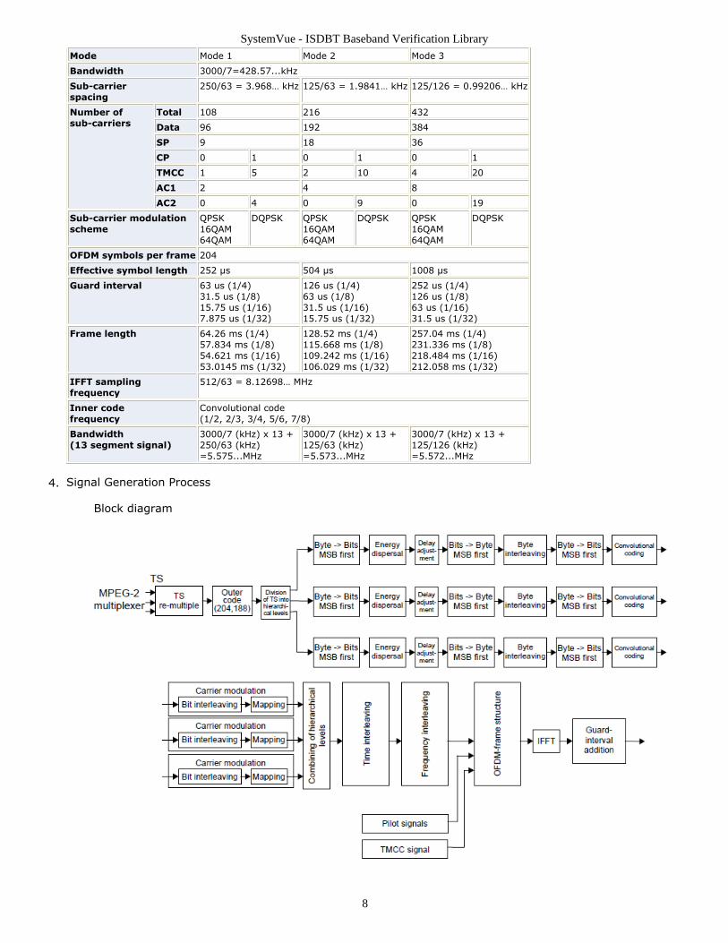
OFDM-Segment Parameters3.
SystemVue - ISDBT Baseband Verification Library
8
Mode Mode 1 Mode 2 Mode 3
Bandwidth 3000/7=428.57...kHz
Sub-carrierspacing
250/63 = 3.968… kHz 125/63 = 1.9841… kHz 125/126 = 0.99206… kHz
Number ofsub-carriers
Total 108 216 432
Data 96 192 384
SP 9 18 36
CP 0 1 0 1 0 1
TMCC 1 5 2 10 4 20
AC1 2 4 8
AC2 0 4 0 9 0 19
Sub-carrier modulationscheme
QPSK16QAM64QAM
DQPSK QPSK16QAM64QAM
DQPSK QPSK16QAM64QAM
DQPSK
OFDM symbols per frame 204
Effective symbol length 252 µs 504 µs 1008 µs
Guard interval 63 us (1/4)31.5 us (1/8)15.75 us (1/16)7.875 us (1/32)
126 us (1/4)63 us (1/8)31.5 us (1/16)15.75 us (1/32)
252 us (1/4)126 us (1/8)63 us (1/16)31.5 us (1/32)
Frame length 64.26 ms (1/4)57.834 ms (1/8)54.621 ms (1/16)53.0145 ms (1/32)
128.52 ms (1/4)115.668 ms (1/8)109.242 ms (1/16)106.029 ms (1/32)
257.04 ms (1/4)231.336 ms (1/8)218.484 ms (1/16)212.058 ms (1/32)
IFFT samplingfrequency
512/63 = 8.12698… MHz
Inner codefrequency
Convolutional code(1/2, 2/3, 3/4, 5/6, 7/8)
Bandwidth(13 segment signal)
3000/7 (kHz) x 13 +250/63 (kHz)=5.575...MHz
3000/7 (kHz) x 13 +125/63 (kHz)=5.573...MHz
3000/7 (kHz) x 13 +125/126 (kHz)=5.572...MHz
Signal Generation Process4.
Block diagram
SystemVue - ISDBT Baseband Verification Library
9
Reed-Solomon encoding. 188-byte TS packets from different data layers arecoded with an Reed-Solomon (204,188) encoderEach 188-byte packet is preceded with 51 0x00 byte and then coded with thenative Reed-Solomon code (255,239) in GF (28). The primitive polynomial is
p(x) = x8 + x4 + x3 + x2 + 1
and the generation polynomial is
g(x) = (x-a0)(x-a1)(x-a2)...(x-a15)
where a = 0x02Byte to Bit conversion. RS encoded bytes are converted to bits, MSB first.
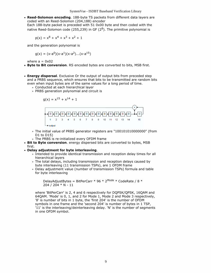
Energy dispersal. Exclusive Or the output of output bits from preceded stepand a PRBS sequence, which ensures that bits to be transmitted are random bitseven when input bytes are of the same values for a long period of time.
Conducted at each hierarchical layerPRBS generation polynomial and circuit is
g(x) = x15 + x14 + 1
The initial value of PRBS generator registers are "100101010000000" (fromD1 to D15)The PRBS is re-initialized every OFDM frame
Bit to Byte conversion. energy dispersed bits are converted to bytes, MSBfirst.Delay adjustment for byte interleaving.
Intended to provide identical transmission and reception delay times for allhierarchical layersThe total delays, including transmission and reception delays caused bybyte interleaving (11 transmission TSPs), are 1 OFDM frameDelay adjustment value (number of transmission TSPs) formula and tablefor byte interleaving
DelayAdjustBytes = BitPerCarr * 96 * 2Mode * CodeRate / 8 *204 / 204 * N - 11
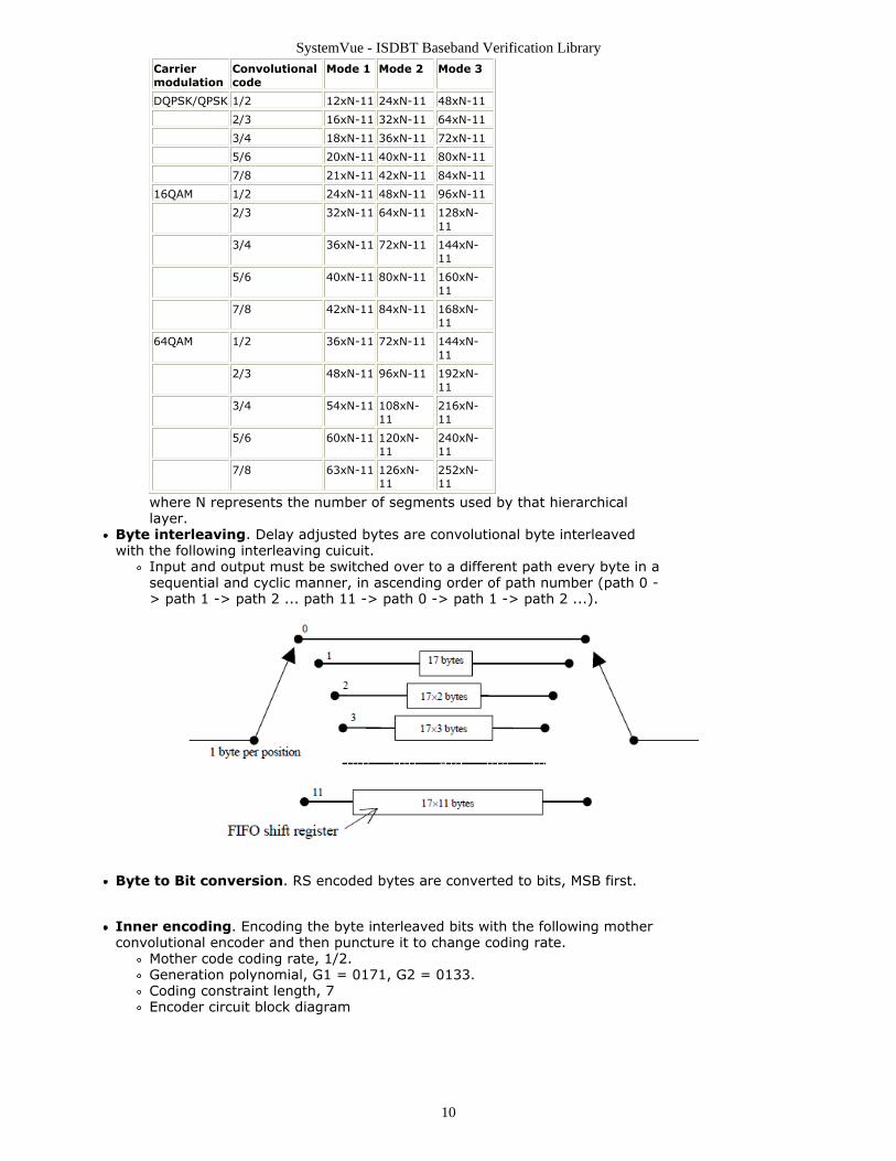
where 'BitPerCarr' is 2, 4 and 6 respectively for DQPSK/QPSK, 16QAM and64QAM. 'Mode' is 0, 1, and 2 for Mode 1, Mode 2 and Mode 3 respectively,'8' is number of bits in 1 byte, the 'first 204' is the number of OFDMsymbols in one frame and the 'second 204' is number of bytes in 1 TSP,'11' is the interleaving/deinterleaving delay. 'N' is the number of segmentsin one OFDM symbol.
SystemVue - ISDBT Baseband Verification Library
10
Carriermodulation
Convolutionalcode
Mode 1 Mode 2 Mode 3
DQPSK/QPSK 1/2 12xN-11 24xN-11 48xN-11
2/3 16xN-11 32xN-11 64xN-11
3/4 18xN-11 36xN-11 72xN-11
5/6 20xN-11 40xN-11 80xN-11
7/8 21xN-11 42xN-11 84xN-11
16QAM 1/2 24xN-11 48xN-11 96xN-11
2/3 32xN-11 64xN-11 128xN-11
3/4 36xN-11 72xN-11 144xN-11
5/6 40xN-11 80xN-11 160xN-11
7/8 42xN-11 84xN-11 168xN-11
64QAM 1/2 36xN-11 72xN-11 144xN-11
2/3 48xN-11 96xN-11 192xN-11
3/4 54xN-11 108xN-11
216xN-11
5/6 60xN-11 120xN-11
240xN-11
7/8 63xN-11 126xN-11
252xN-11
where N represents the number of segments used by that hierarchicallayer.
Byte interleaving. Delay adjusted bytes are convolutional byte interleavedwith the following interleaving cuicuit.
Input and output must be switched over to a different path every byte in asequential and cyclic manner, in ascending order of path number (path 0 -> path 1 -> path 2 ... path 11 -> path 0 -> path 1 -> path 2 ...).
Byte to Bit conversion. RS encoded bytes are converted to bits, MSB first.
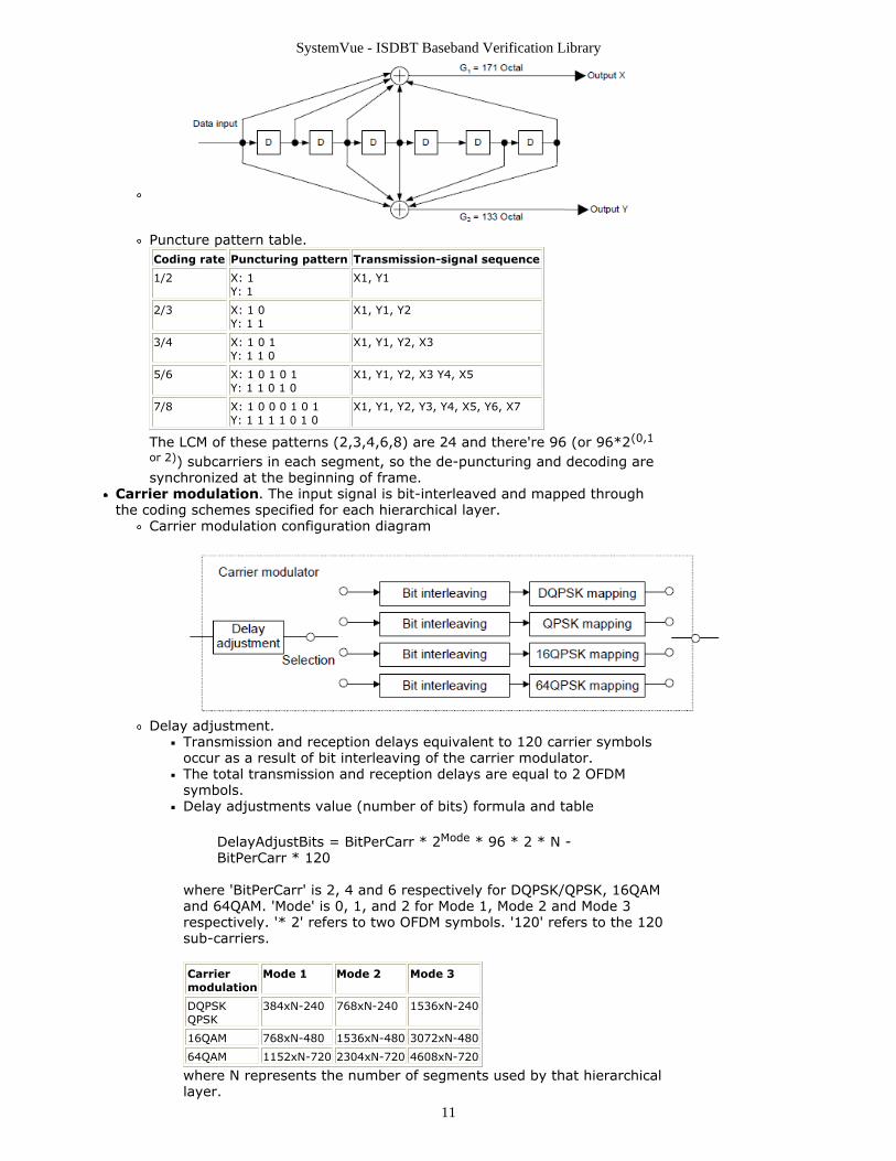
Inner encoding. Encoding the byte interleaved bits with the following motherconvolutional encoder and then puncture it to change coding rate.
Mother code coding rate, 1/2.Generation polynomial, G1 = 0171, G2 = 0133.Coding constraint length, 7Encoder circuit block diagram
SystemVue - ISDBT Baseband Verification Library
11
Puncture pattern table.Coding rate Puncturing pattern Transmission-signal sequence
1/2 X: 1Y: 1
X1, Y1
2/3 X: 1 0Y: 1 1
X1, Y1, Y2
3/4 X: 1 0 1Y: 1 1 0
X1, Y1, Y2, X3
5/6 X: 1 0 1 0 1Y: 1 1 0 1 0
X1, Y1, Y2, X3 Y4, X5
7/8 X: 1 0 0 0 1 0 1Y: 1 1 1 1 0 1 0
X1, Y1, Y2, Y3, Y4, X5, Y6, X7
The LCM of these patterns (2,3,4,6,8) are 24 and there're 96 (or 96*2(0,1
or 2)) subcarriers in each segment, so the de-puncturing and decoding aresynchronized at the beginning of frame.
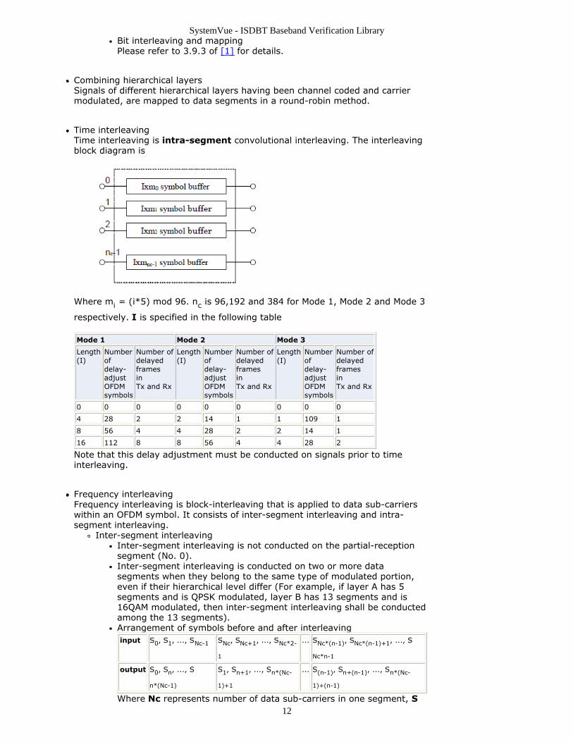
Carrier modulation. The input signal is bit-interleaved and mapped throughthe coding schemes specified for each hierarchical layer.
Carrier modulation configuration diagram
Delay adjustment.Transmission and reception delays equivalent to 120 carrier symbolsoccur as a result of bit interleaving of the carrier modulator.The total transmission and reception delays are equal to 2 OFDMsymbols.Delay adjustments value (number of bits) formula and table
DelayAdjustBits = BitPerCarr * 2Mode * 96 * 2 * N -BitPerCarr * 120
where 'BitPerCarr' is 2, 4 and 6 respectively for DQPSK/QPSK, 16QAMand 64QAM. 'Mode' is 0, 1, and 2 for Mode 1, Mode 2 and Mode 3respectively. '* 2' refers to two OFDM symbols. '120' refers to the 120sub-carriers.
Carriermodulation
Mode 1 Mode 2 Mode 3
DQPSKQPSK
384xN-240 768xN-240 1536xN-240
16QAM 768xN-480 1536xN-480 3072xN-480
64QAM 1152xN-720 2304xN-720 4608xN-720
where N represents the number of segments used by that hierarchicallayer.
SystemVue - ISDBT Baseband Verification Library
12
Bit interleaving and mappingPlease refer to 3.9.3 of [1] for details.
Combining hierarchical layersSignals of different hierarchical layers having been channel coded and carriermodulated, are mapped to data segments in a round-robin method.
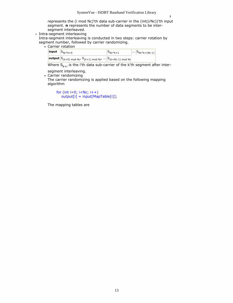
Time interleavingTime interleaving is intra-segment convolutional interleaving. The interleavingblock diagram is
Where mi = (i*5) mod 96. nc is 96,192 and 384 for Mode 1, Mode 2 and Mode 3
respectively. I is specified in the following table
Mode 1 Mode 2 Mode 3
Length(I)
Numberofdelay-adjustOFDMsymbols
Number ofdelayedframesinTx and Rx
Length(I)
Numberofdelay-adjustOFDMsymbols
Number ofdelayedframesinTx and Rx
Length(I)
Numberofdelay-adjustOFDMsymbols
Number ofdelayedframesinTx and Rx
0 0 0 0 0 0 0 0 0
4 28 2 2 14 1 1 109 1
8 56 4 4 28 2 2 14 1
16 112 8 8 56 4 4 28 2
Note that this delay adjustment must be conducted on signals prior to timeinterleaving.
Frequency interleavingFrequency interleaving is block-interleaving that is applied to data sub-carrierswithin an OFDM symbol. It consists of inter-segment interleaving and intra-segment interleaving.
Inter-segment interleavingInter-segment interleaving is not conducted on the partial-receptionsegment (No. 0).Inter-segment interleaving is conducted on two or more datasegments when they belong to the same type of modulated portion,even if their hierarchical level differ (For example, if layer A has 5segments and is QPSK modulated, layer B has 13 segments and is16QAM modulated, then inter-segment interleaving shall be conductedamong the 13 segments).Arrangement of symbols before and after interleavinginput S0, S1, ..., SNc-1 SNc, SNc+1, ..., SNc*2-
1
... SNc*(n-1), SNc*(n-1)+1, ..., S
Nc*n-1
output S0, Sn, ..., S
n*(Nc-1)
S1, Sn+1, ..., Sn*(Nc-
1)+1
... S(n-1), Sn+(n-1), ..., Sn*(Nc-
1)+(n-1)
Where Nc represents number of data sub-carriers in one segment, S
SystemVue - ISDBT Baseband Verification Library
13
i
represents the (i mod Nc)'th data sub-carrier in the (int(i/Nc))'th inputsegment. n represents the number of data segments to be inter-segment interleaved.
Intra-segment interleavingIntra-segment interleaving is conducted in two steps: carrier rotation bysegment number, followed by carrier randomizing.
Carrier rotationinput SNc*k+0 SNc*k+1 ... SNc*k+(Nc-1)
output S(k+0) mod Nc, S(k+1) mod Nc, ... S(k+Nc-1) mod Nc
Where Sk+i is the i'th data sub-carrier of the k'th segment after inter-
segment interleaving.Carrier randomizingThe carrier randomizing is applied based on the following mappingalgorithm
for (int i=0; i<Nc; i++) output[i] = input[MapTable[i]];
The mapping tables are
SystemVue - ISDBT Baseband Verification Library
14
Mode mapping table (MapTable)
Mode1
{80, 93, 63, 92, 94, 55, 17, 81, 6, 51, 9, 85, 89, 65, 52, 15, 73, 66, 46, 71,12, 70, 18, 13,95, 34, 1, 38, 78, 59, 91, 64, 0, 28, 11, 4, 45, 35, 16, 7, 48, 22, 23, 77, 56,19, 8, 36,39, 61, 21, 3, 26, 69, 67, 20, 74, 86, 72, 25, 31, 5, 49, 42, 54, 87, 43, 60,29, 2, 76, 84,83, 40, 14, 79, 27, 57, 44, 37, 30, 68, 47, 88, 75, 41, 90, 10, 33, 32, 62, 50,58, 82, 53, 24}
Mode2
{98, 35, 67, 116, 135, 17, 5, 93, 73, 168, 54, 143, 43, 74, 165, 48, 37, 69,154, 150, 107, 76, 176, 79,175, 36, 28, 78, 47, 128, 94, 163, 184, 72, 142, 2, 86, 14, 130, 151, 114,68, 46, 183, 122, 112, 180, 42,105, 97, 33, 134, 177, 84, 170, 45, 187, 38, 167, 10, 189, 51, 117, 156,161, 25, 89, 125, 139, 24, 19, 57,71, 39, 77, 191, 88, 85, 0, 162, 181, 113, 140, 61, 75, 82, 101, 174, 118,20, 136, 3, 121, 190, 120, 92,160, 52, 153, 127, 65, 60, 133, 147, 131, 87, 22, 58, 100, 111, 141, 83, 49,132, 12, 155, 146, 102, 164, 66,1, 62, 178, 15, 182, 96, 80, 119, 23, 6, 166, 56, 99, 123, 138, 137, 21, 145,185, 18, 70, 129, 95, 90,149, 109, 124, 50, 11, 152, 4, 31, 172, 40, 13, 32, 55, 159, 41, 8, 7, 144,16, 26, 173, 81, 44, 103,64, 9, 30, 157, 126, 179, 148, 63, 188, 171, 106, 104, 158, 115, 34, 186,29, 108, 53, 91, 169, 110, 27, 59}
Mode3
{62, 13, 371, 11, 285, 336, 365, 220, 226, 92, 56, 46, 120, 175, 298, 352,172, 235, 53, 164, 368, 187, 125, 82,5, 45, 173, 258, 135, 182, 141, 273, 126, 264, 286, 88, 233, 61, 249, 367,310, 179, 155, 57, 123, 208, 14, 227,100, 311, 205, 79, 184, 185, 328, 77, 115, 277, 112, 20, 199, 178, 143,152, 215, 204, 139, 234, 358, 192, 309, 183,81, 129, 256, 314, 101, 43, 97, 324, 142, 157, 90, 214, 102, 29, 303, 363,261, 31, 22, 52, 305, 301, 293, 177,116, 296, 85, 196, 191, 114, 58, 198, 16, 167, 145, 119, 245, 113, 295,193, 232, 17, 108, 283, 246, 64, 237, 189,128, 373, 302, 320, 239, 335, 356, 39, 347, 351, 73, 158, 276, 243, 99, 38,287, 3, 330, 153, 315, 117, 289, 213,210, 149, 383, 337, 339, 151, 241, 321, 217, 30, 334, 161, 322, 49, 176,359, 12, 346, 60, 28, 229, 265, 288, 225,382, 59, 181, 170, 319, 341, 86, 251, 133, 344, 361, 109, 44, 369, 268,257, 323, 55, 317, 381, 121, 360, 260, 275,190, 19, 63, 18, 248, 9, 240, 211, 150, 230, 332, 231, 71, 255, 350, 355,83, 87, 154, 218, 138, 269, 348, 130,160, 278, 377, 216, 236, 308, 223, 254, 25, 98, 300, 201, 137, 219, 36,325, 124, 66, 353, 169, 21, 35, 107, 50,106, 333, 326, 262, 252, 271, 263, 372, 136, 0, 366, 206, 159, 122, 188, 6,284, 96, 26, 200, 197, 186, 345, 340,349, 103, 84, 228, 212, 2, 67, 318, 1, 74, 342, 166, 194, 33, 68, 267, 111,118, 140, 195, 105, 202, 291, 259,23, 171, 65, 281, 24, 165, 8, 94, 222, 331, 34, 238, 364, 376, 266, 89, 80,253, 163, 280, 247, 4, 362, 379,290, 279, 54, 78, 180, 72, 316, 282, 131, 207, 343, 370, 306, 221, 132, 7,148, 299, 168, 224, 48, 47, 357, 313,75, 104, 70, 147, 40, 110, 374, 69, 146, 37, 375, 354, 174, 41, 32, 304,307, 312, 15, 272, 134, 242, 203, 209,380, 162, 297, 327, 10, 93, 42, 250, 156, 338, 292, 144, 378, 294, 329,127, 270, 76, 95, 91, 244, 274, 27, 51}
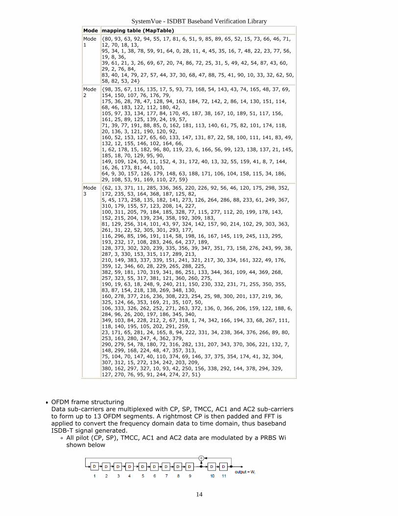
OFDM frame structuringData sub-carriers are multiplexed with CP, SP, TMCC, AC1 and AC2 sub-carriersto form up to 13 OFDM segments. A rightmost CP is then padded and FFT isapplied to convert the frequency domain data to time domain, thus basebandISDB-T signal generated.
All pilot (CP, SP), TMCC, AC1 and AC2 data are modulated by a PRBS Wishown below
SystemVue - ISDBT Baseband Verification Library
15
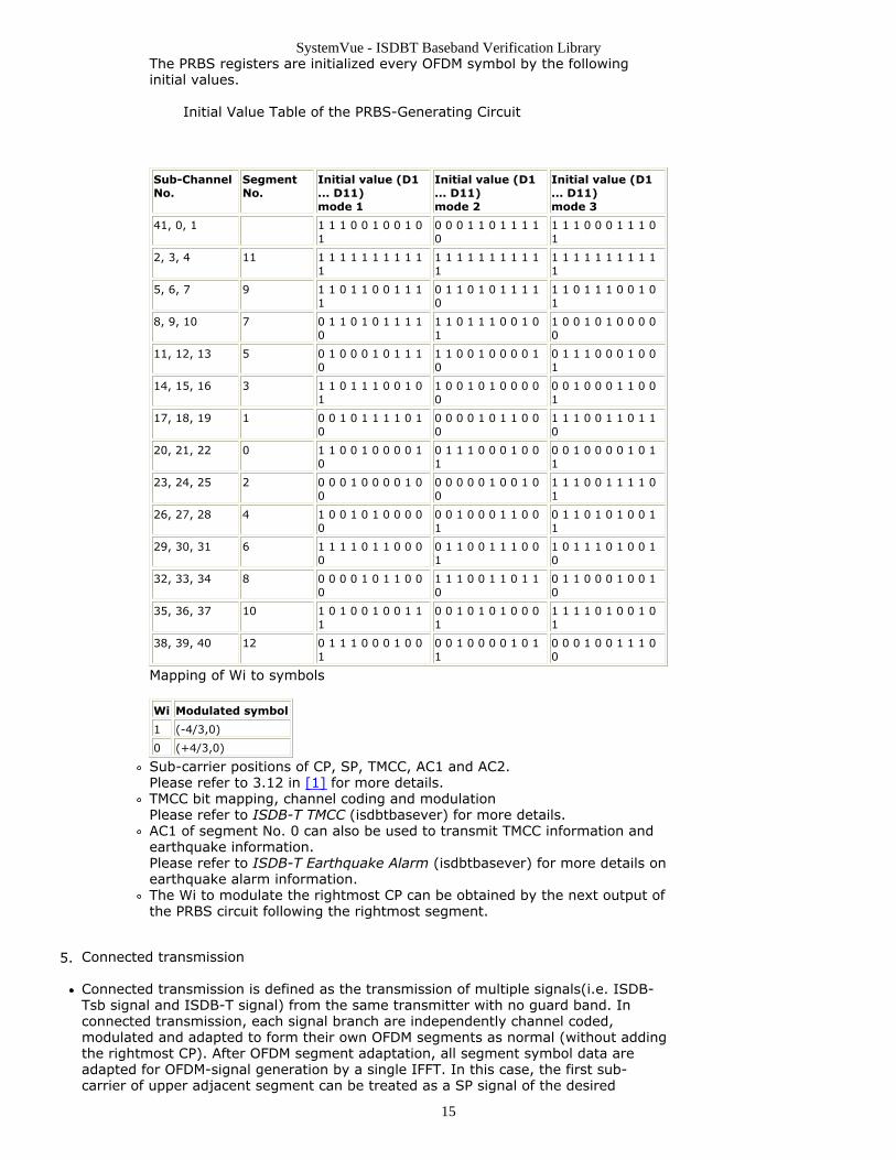
The PRBS registers are initialized every OFDM symbol by the followinginitial values.
Initial Value Table of the PRBS-Generating Circuit
Sub-ChannelNo.
SegmentNo.
Initial value (D1... D11)mode 1
Initial value (D1... D11)mode 2
Initial value (D1... D11)mode 3
41, 0, 1 1 1 1 0 0 1 0 0 1 01
0 0 0 1 1 0 1 1 1 10
1 1 1 0 0 0 1 1 1 01
2, 3, 4 11 1 1 1 1 1 1 1 1 1 11
1 1 1 1 1 1 1 1 1 11
1 1 1 1 1 1 1 1 1 11
5, 6, 7 9 1 1 0 1 1 0 0 1 1 11
0 1 1 0 1 0 1 1 1 10
1 1 0 1 1 1 0 0 1 01
8, 9, 10 7 0 1 1 0 1 0 1 1 1 10
1 1 0 1 1 1 0 0 1 01
1 0 0 1 0 1 0 0 0 00
11, 12, 13 5 0 1 0 0 0 1 0 1 1 10
1 1 0 0 1 0 0 0 0 10
0 1 1 1 0 0 0 1 0 01
14, 15, 16 3 1 1 0 1 1 1 0 0 1 01
1 0 0 1 0 1 0 0 0 00
0 0 1 0 0 0 1 1 0 01
17, 18, 19 1 0 0 1 0 1 1 1 1 0 10
0 0 0 0 1 0 1 1 0 00
1 1 1 0 0 1 1 0 1 10
20, 21, 22 0 1 1 0 0 1 0 0 0 0 10
0 1 1 1 0 0 0 1 0 01
0 0 1 0 0 0 0 1 0 11
23, 24, 25 2 0 0 0 1 0 0 0 0 1 00
0 0 0 0 0 1 0 0 1 00
1 1 1 0 0 1 1 1 1 01
26, 27, 28 4 1 0 0 1 0 1 0 0 0 00
0 0 1 0 0 0 1 1 0 01
0 1 1 0 1 0 1 0 0 11
29, 30, 31 6 1 1 1 1 0 1 1 0 0 00
0 1 1 0 0 1 1 1 0 01
1 0 1 1 1 0 1 0 0 10
32, 33, 34 8 0 0 0 0 1 0 1 1 0 00
1 1 1 0 0 1 1 0 1 10
0 1 1 0 0 0 1 0 0 10
35, 36, 37 10 1 0 1 0 0 1 0 0 1 11
0 0 1 0 1 0 1 0 0 01
1 1 1 1 0 1 0 0 1 01
38, 39, 40 12 0 1 1 1 0 0 0 1 0 01
0 0 1 0 0 0 0 1 0 11
0 0 0 1 0 0 1 1 1 00
Mapping of Wi to symbols
Wi Modulated symbol
1 (-4/3,0)
0 (+4/3,0)
Sub-carrier positions of CP, SP, TMCC, AC1 and AC2.Please refer to 3.12 in [1] for more details.TMCC bit mapping, channel coding and modulationPlease refer to ISDB-T TMCC (isdbtbasever) for more details.AC1 of segment No. 0 can also be used to transmit TMCC information andearthquake information.Please refer to ISDB-T Earthquake Alarm (isdbtbasever) for more details onearthquake alarm information.The Wi to modulate the rightmost CP can be obtained by the next output ofthe PRBS circuit following the rightmost segment.
Connected transmission5.
Connected transmission is defined as the transmission of multiple signals(i.e. ISDB-Tsb signal and ISDB-T signal) from the same transmitter with no guard band. Inconnected transmission, each signal branch are independently channel coded,modulated and adapted to form their own OFDM segments as normal (without addingthe rightmost CP). After OFDM segment adaptation, all segment symbol data areadapted for OFDM-signal generation by a single IFFT. In this case, the first sub-carrier of upper adjacent segment can be treated as a SP signal of the desired
SystemVue - ISDBT Baseband Verification Library
16
segment, so only one CP is added to the right side of the rightmost segment.Phase compensation for the difference of center frequency.Assuming the center frequency of a desireed ISDB-Tsb/ISDB-T signal in a connectedtransmission is fr, and the center frequency of the connected transmission band is ft.When a receiver filtering out the desired signal and down-convert the signal with alocal carrier whose center frequency is fr, a phase rotation of Φ=-(fr-ft)*TGI will be
introduced between consecutive OFDM symbols due to the guard interval insertion.The phase rotation is compensated in the transmitter side. The amount of phasecompensation is
Φ(δf) = 2π * δf * GIR * 2Mode
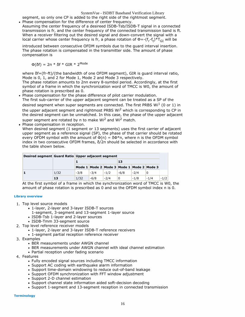
where δf=(fr-ft)/(the bandwidth of one OFDM segment), GIR is guard interval ratio,Mode is 0, 1, and 2 for Mode 1, Mode 2 and Mode 3 respectively.The phase rotation amounts to 2nπ every 8-symbol period. Accordingly, at the firstsymbol of a frame in which the synchronization word of TMCC is W0, the amount ofphase rotation is prescribed as 0.Phase compensation for the phase difference of pilot carrier modulation.The first sub-carrier of the upper adjacent segment can be treated as a SP of thedesired segment when super segments are connected. The first PRBS Wi1 (0 or 1) inthe upper adjacent segment and rightmost PRBS Wi2 which is corresponding to CP inthe desired segment can be unmatched. In this case, the phase of the upper adjacentsuper segment are rotated by π to make Wi2 and Wi2 match.Phase compensation in reception.When desired segment (1 segment or 13 segments) uses the first carrier of adjacentupper segment as a reference signal (SP), the phase of that carrier should be rotatedevery OFDM symbol with the amount of Φ(n) = δΦ*n, where n is the OFDM symbolindex in two consecutive OFDM frames, δ/2π should be selected in accordance withthe table shown below. Desired segment Guard Ratio Upper adjacent segment
1 13
Mode 1 Mode 2 Mode 3 Mode 1 Mode 2 Mode 3
1 1/32 -3/8 -3/4 -1/2 -6/8 -2/4 0
13 1/32 -6/8 -2/4 0 -1/8 -1/4 -1/2
At the first symbol of a frame in which the synchronization word of TMCC is W0, theamount of phase rotation is prescribed as 0 and so the OFDM symbol index n is 0.
Library overview
Top level source models1.1-layer, 2-layer and 3-layer ISDB-T sources1-segment, 3-segment and 13-segment 1-layer sourceISDB-Tsb 1-layer and 2-layer sourcesISDB-Tmm 33-segment source
Top level reference receiver models2.1-layer, 2-layer and 3-layer ISDB-T reference receivers1-segment partial reception reference receiver
Examples3.BER measurements under AWGN channelBER measurements under AWGN channel with ideal channel estimationPartial reception under fading scenario
Features4.Fully encoded signal sources including TMCC informationSupport AC coding with earthquake alarm informationSupport time-domain windowing to reduce out-of-band leakageSupport OFDM synchronization with FFT window adjustmentSupport 2-D channel estimationSupport channel state information aided soft-decision decodingSupport 1-segment and 13-segment reception in connected transmission
Terminology
SystemVue - ISDBT Baseband Verification Library
17
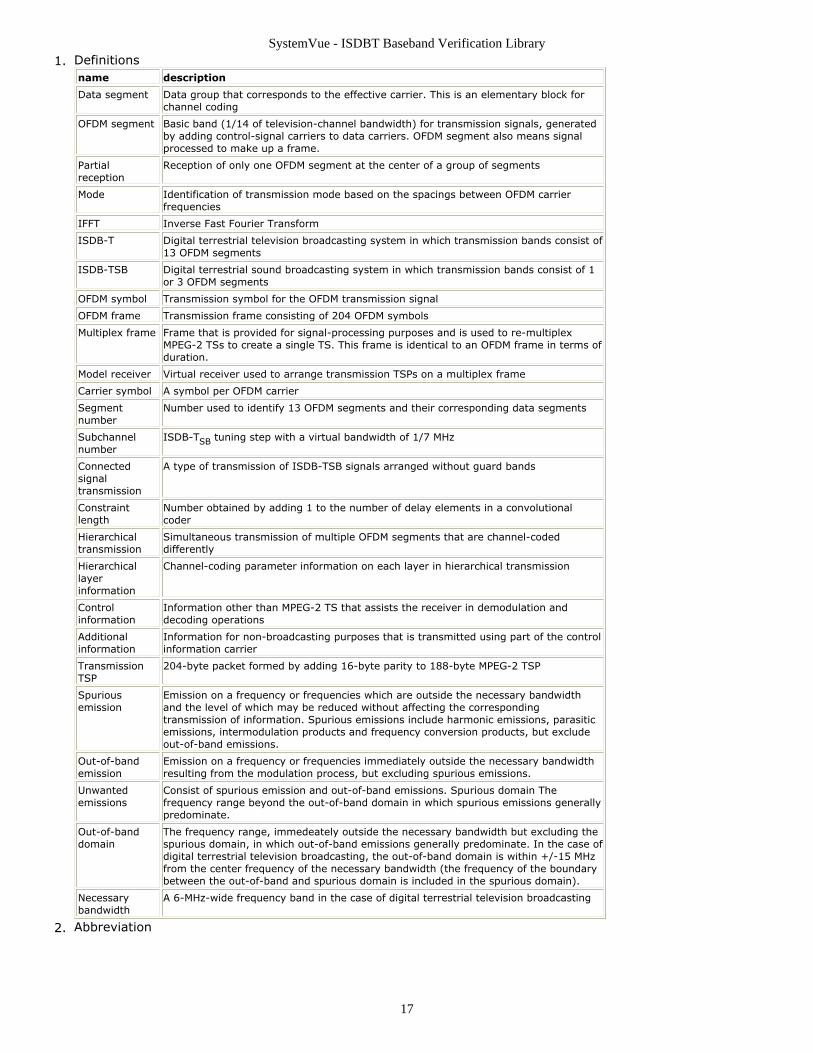
Definitions1.name description
Data segment Data group that corresponds to the effective carrier. This is an elementary block forchannel coding
OFDM segment Basic band (1/14 of television-channel bandwidth) for transmission signals, generatedby adding control-signal carriers to data carriers. OFDM segment also means signalprocessed to make up a frame.
Partialreception
Reception of only one OFDM segment at the center of a group of segments
Mode Identification of transmission mode based on the spacings between OFDM carrierfrequencies
IFFT Inverse Fast Fourier Transform
ISDB-T Digital terrestrial television broadcasting system in which transmission bands consist of13 OFDM segments
ISDB-TSB Digital terrestrial sound broadcasting system in which transmission bands consist of 1or 3 OFDM segments
OFDM symbol Transmission symbol for the OFDM transmission signal
OFDM frame Transmission frame consisting of 204 OFDM symbols
Multiplex frame Frame that is provided for signal-processing purposes and is used to re-multiplexMPEG-2 TSs to create a single TS. This frame is identical to an OFDM frame in terms ofduration.
Model receiver Virtual receiver used to arrange transmission TSPs on a multiplex frame
Carrier symbol A symbol per OFDM carrier
Segmentnumber
Number used to identify 13 OFDM segments and their corresponding data segments
Subchannelnumber
ISDB-TSB tuning step with a virtual bandwidth of 1/7 MHz
Connectedsignaltransmission
A type of transmission of ISDB-TSB signals arranged without guard bands
Constraintlength
Number obtained by adding 1 to the number of delay elements in a convolutionalcoder
Hierarchicaltransmission
Simultaneous transmission of multiple OFDM segments that are channel-codeddifferently
Hierarchicallayerinformation
Channel-coding parameter information on each layer in hierarchical transmission
Controlinformation
Information other than MPEG-2 TS that assists the receiver in demodulation anddecoding operations
Additionalinformation
Information for non-broadcasting purposes that is transmitted using part of the controlinformation carrier
TransmissionTSP
204-byte packet formed by adding 16-byte parity to 188-byte MPEG-2 TSP
Spuriousemission
Emission on a frequency or frequencies which are outside the necessary bandwidthand the level of which may be reduced without affecting the correspondingtransmission of information. Spurious emissions include harmonic emissions, parasiticemissions, intermodulation products and frequency conversion products, but excludeout-of-band emissions.
Out-of-bandemission
Emission on a frequency or frequencies immediately outside the necessary bandwidthresulting from the modulation process, but excluding spurious emissions.
Unwantedemissions
Consist of spurious emission and out-of-band emissions. Spurious domain Thefrequency range beyond the out-of-band domain in which spurious emissions generallypredominate.
Out-of-banddomain
The frequency range, immedeately outside the necessary bandwidth but excluding thespurious domain, in which out-of-band emissions generally predominate. In the case ofdigital terrestrial television broadcasting, the out-of-band domain is within +/-15 MHzfrom the center frequency of the necessary bandwidth (the frequency of the boundarybetween the out-of-band and spurious domain is included in the spurious domain).
Necessarybandwidth
A 6-MHz-wide frequency band in the case of digital terrestrial television broadcasting
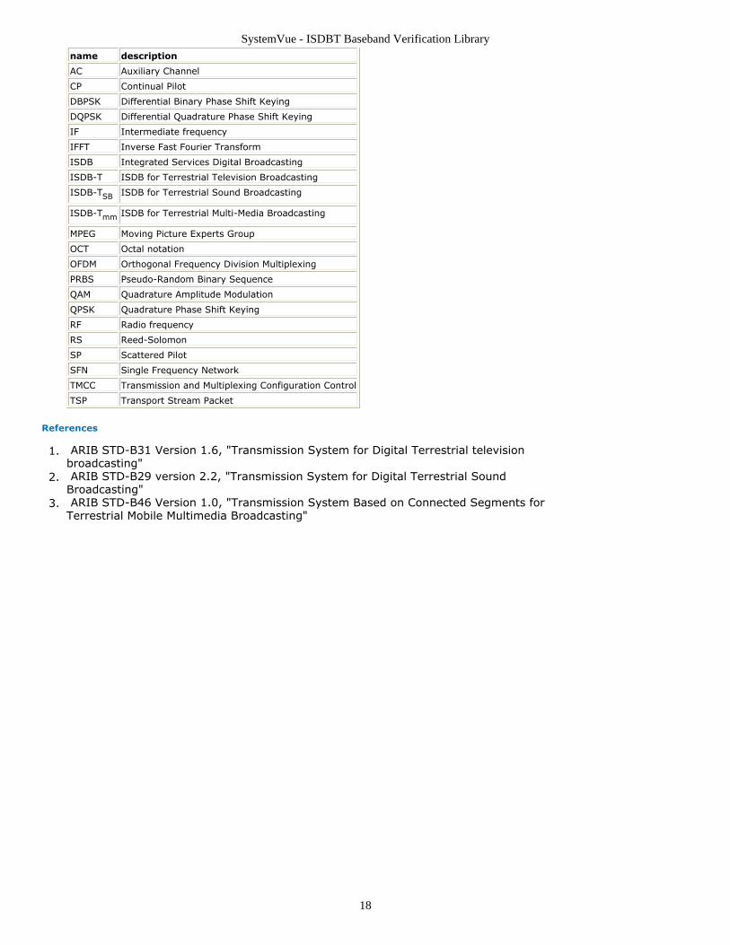
Abbreviation2.
SystemVue - ISDBT Baseband Verification Library
18
name description
AC Auxiliary Channel
CP Continual Pilot
DBPSK Differential Binary Phase Shift Keying
DQPSK Differential Quadrature Phase Shift Keying
IF Intermediate frequency
IFFT Inverse Fast Fourier Transform
ISDB Integrated Services Digital Broadcasting
ISDB-T ISDB for Terrestrial Television Broadcasting
ISDB-TSB ISDB for Terrestrial Sound Broadcasting
ISDB-Tmm ISDB for Terrestrial Multi-Media Broadcasting
MPEG Moving Picture Experts Group
OCT Octal notation
OFDM Orthogonal Frequency Division Multiplexing
PRBS Pseudo-Random Binary Sequence
QAM Quadrature Amplitude Modulation
QPSK Quadrature Phase Shift Keying
RF Radio frequency
RS Reed-Solomon
SP Scattered Pilot
SFN Single Frequency Network
TMCC Transmission and Multiplexing Configuration Control
TSP Transport Stream Packet
References
ARIB STD-B31 Version 1.6, "Transmission System for Digital Terrestrial television1.broadcasting" ARIB STD-B29 version 2.2, "Transmission System for Digital Terrestrial Sound2.Broadcasting" ARIB STD-B46 Version 1.0, "Transmission System Based on Connected Segments for3.Terrestrial Mobile Multimedia Broadcasting"
SystemVue - ISDBT Baseband Verification Library
19
ISDBT Channel Coding Category Contents
ISDBT CDSCDecoder Part (isdbtbasever)ISDBT ChCoder Part (isdbtbasever)ISDBT ChDecoder Part (isdbtbasever)ISDBT Derandomize Part (isdbtbasever)ISDBT LFSRCoder Part (isdbtbasever)ISDBT PNGenerator Part (isdbtbasever)ISDBT PuncCoder Part (isdbtbasever)ISDBT PuncDecoder Part (isdbtbasever)ISDBT Randomize Part (isdbtbasever)
SystemVue - ISDBT Baseband Verification Library
20
ISDBT_CDSCDecoder PartCategories: Channel Coding (isdbtbasever)
The models associated with this part are listed below. To view detailed information on amodel (description, parameters, equations, notes, etc.), please click the appropriate link.
Model Description
ISDBT_CDSCDecoder (isdbtbasever) Complete differential set code (273,191)decoder
ISDBT_CDSCDecoder
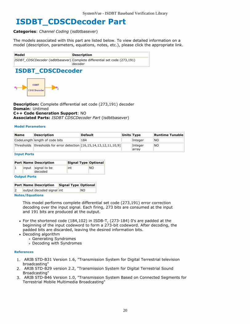
Description: Complete differential set code (273,191) decoderDomain: UntimedC++ Code Generation Support: NOAssociated Parts: ISDBT CDSCDecoder Part (isdbtbasever)
Model Parameters
Name Description Default Units Type Runtime Tunable
CodeLength length of code bits 184 Integer NO
Thresholds thresholds for error detection [16,15,14,13,12,11,10,9] Integerarray
NO
Input Ports
Port Name Description Signal Type Optional
1 input signal to bedecoded
int NO
Output Ports
Port Name Description Signal Type Optional
2 output decoded signal int NO
Notes/Equations
This model performs complete differential set code (273,191) error correctiondecoding over the input signal. Each firing, 273 bits are consumed at the inputand 191 bits are produced at the output.
For the shortened code (184,102) in ISDB-T, (273-184) 0's are padded at thebeginning of the input codeword to form a 273-bit codeword. After decoding, thepadded bits are discarded, leaving the desired information bits.Decoding algorithm
Generating SyndromesDecoding with Syndromes
References
ARIB STD-B31 Version 1.6, "Transmission System for Digital Terrestrial television1.broadcasting" ARIB STD-B29 version 2.2, "Transmission System for Digital Terrestrial Sound2.Broadcasting" ARIB STD-B46 Version 1.0, "Transmission System Based on Connected Segments for3.Terrestrial Mobile Multimedia Broadcasting"
SystemVue - ISDBT Baseband Verification Library
21
ISDBT_ChCoder Part Channel coder of ISDBT-T
Categories: Channel Coding (isdbtbasever)
The models associated with this part are listed below. To view detailed information on amodel (description, parameters, equations, notes, etc.), please click the appropriate link.
Model
ISDBT_ChCoder (isdbtbasever)
ISDBT_ChCoder
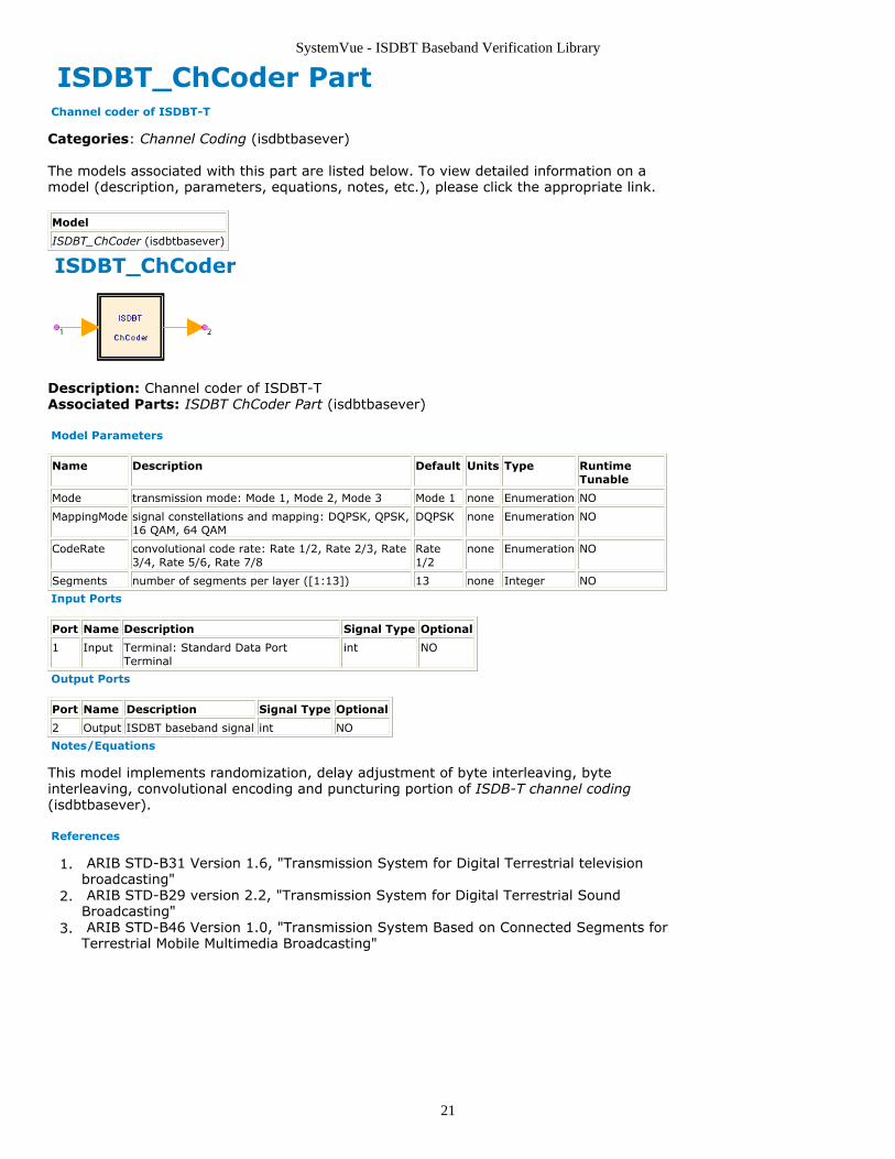
Description: Channel coder of ISDBT-TAssociated Parts: ISDBT ChCoder Part (isdbtbasever)
Model Parameters
Name Description Default Units Type RuntimeTunable
Mode transmission mode: Mode 1, Mode 2, Mode 3 Mode 1 none Enumeration NO
MappingMode signal constellations and mapping: DQPSK, QPSK,16 QAM, 64 QAM
DQPSK none Enumeration NO
CodeRate convolutional code rate: Rate 1/2, Rate 2/3, Rate3/4, Rate 5/6, Rate 7/8
Rate1/2
none Enumeration NO
Segments number of segments per layer ([1:13]) 13 none Integer NO
Input Ports
Port Name Description Signal Type Optional
1 Input Terminal: Standard Data PortTerminal
int NO
Output Ports
Port Name Description Signal Type Optional
2 Output ISDBT baseband signal int NO
Notes/Equations
This model implements randomization, delay adjustment of byte interleaving, byteinterleaving, convolutional encoding and puncturing portion of ISDB-T channel coding(isdbtbasever).
References
ARIB STD-B31 Version 1.6, "Transmission System for Digital Terrestrial television1.broadcasting" ARIB STD-B29 version 2.2, "Transmission System for Digital Terrestrial Sound2.Broadcasting" ARIB STD-B46 Version 1.0, "Transmission System Based on Connected Segments for3.Terrestrial Mobile Multimedia Broadcasting"
SystemVue - ISDBT Baseband Verification Library
22
ISDBT_ChDecoder Part Channel decoder of ISDBT-T
Categories: Channel Coding (isdbtbasever)
The models associated with this part are listed below. To view detailed information on amodel (description, parameters, equations, notes, etc.), please click the appropriate link.
Model
ISDBT_ChDecoder (isdbtbasever)
ISDBT_ChDecoder
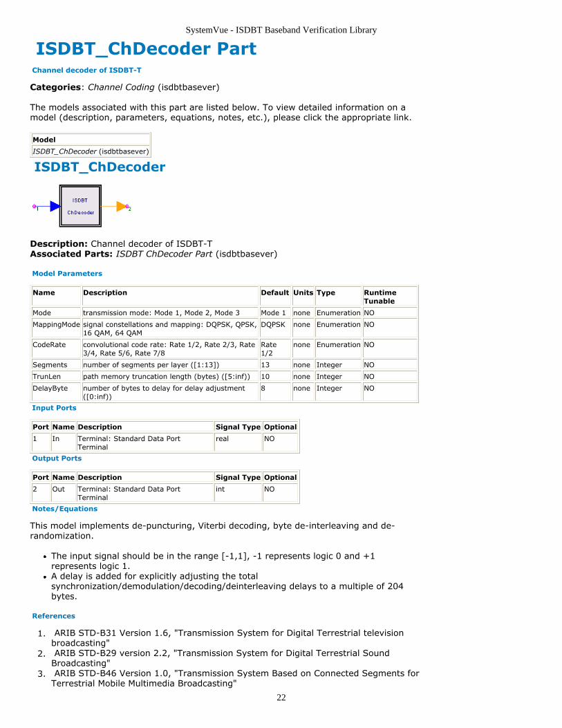
Description: Channel decoder of ISDBT-TAssociated Parts: ISDBT ChDecoder Part (isdbtbasever)
Model Parameters
Name Description Default Units Type RuntimeTunable
Mode transmission mode: Mode 1, Mode 2, Mode 3 Mode 1 none Enumeration NO
MappingMode signal constellations and mapping: DQPSK, QPSK,16 QAM, 64 QAM
DQPSK none Enumeration NO
CodeRate convolutional code rate: Rate 1/2, Rate 2/3, Rate3/4, Rate 5/6, Rate 7/8
Rate1/2
none Enumeration NO
Segments number of segments per layer ([1:13]) 13 none Integer NO
TrunLen path memory truncation length (bytes) ([5:inf)) 10 none Integer NO
DelayByte number of bytes to delay for delay adjustment([0:inf))
8 none Integer NO
Input Ports
Port Name Description Signal Type Optional
1 In Terminal: Standard Data PortTerminal
real NO
Output Ports
Port Name Description Signal Type Optional
2 Out Terminal: Standard Data PortTerminal
int NO
Notes/Equations
This model implements de-puncturing, Viterbi decoding, byte de-interleaving and de-randomization.
The input signal should be in the range [-1,1], -1 represents logic 0 and +1represents logic 1.A delay is added for explicitly adjusting the totalsynchronization/demodulation/decoding/deinterleaving delays to a multiple of 204bytes.
References
ARIB STD-B31 Version 1.6, "Transmission System for Digital Terrestrial television1.broadcasting" ARIB STD-B29 version 2.2, "Transmission System for Digital Terrestrial Sound2.Broadcasting" ARIB STD-B46 Version 1.0, "Transmission System Based on Connected Segments for3.Terrestrial Mobile Multimedia Broadcasting"
SystemVue - ISDBT Baseband Verification Library
23
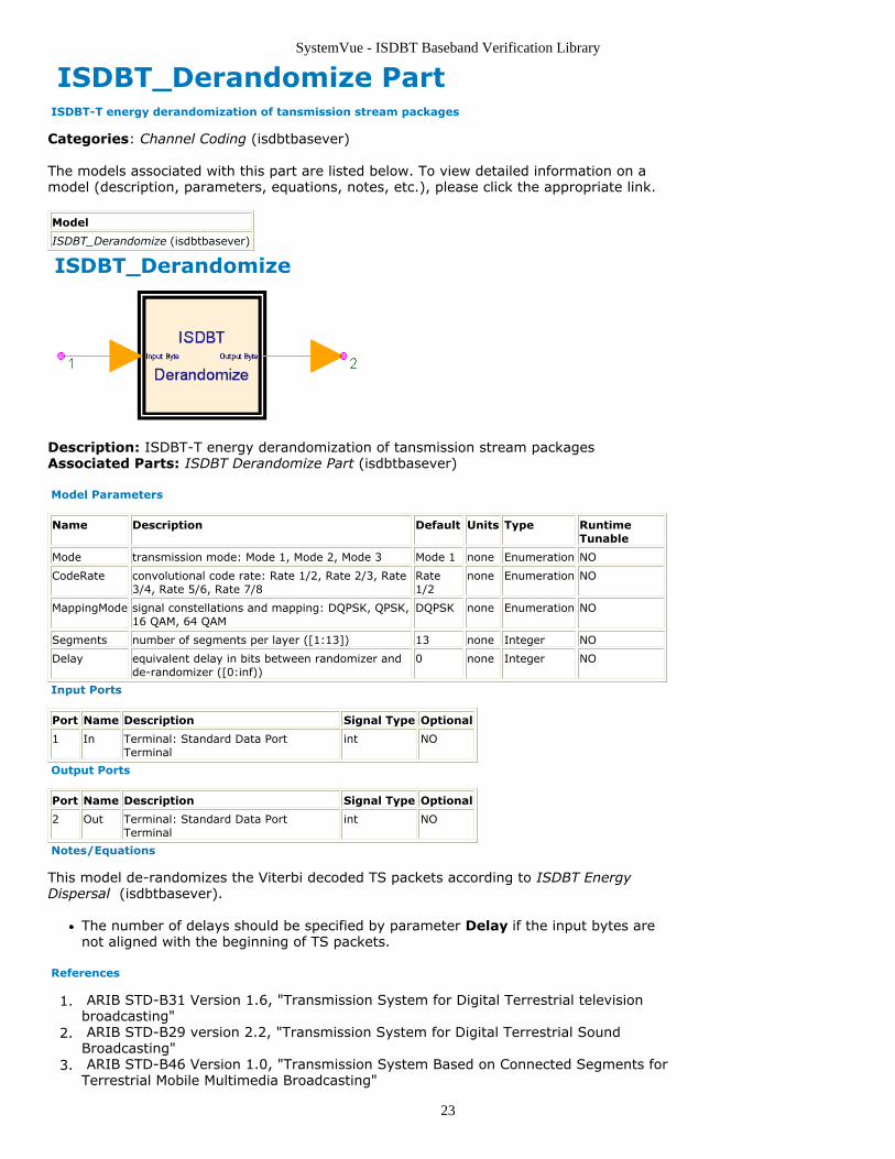
ISDBT_Derandomize Part ISDBT-T energy derandomization of tansmission stream packages
Categories: Channel Coding (isdbtbasever)
The models associated with this part are listed below. To view detailed information on amodel (description, parameters, equations, notes, etc.), please click the appropriate link.
Model
ISDBT_Derandomize (isdbtbasever)
ISDBT_Derandomize
Description: ISDBT-T energy derandomization of tansmission stream packagesAssociated Parts: ISDBT Derandomize Part (isdbtbasever)
Model Parameters
Name Description Default Units Type RuntimeTunable
Mode transmission mode: Mode 1, Mode 2, Mode 3 Mode 1 none Enumeration NO
CodeRate convolutional code rate: Rate 1/2, Rate 2/3, Rate3/4, Rate 5/6, Rate 7/8
Rate1/2
none Enumeration NO
MappingMode signal constellations and mapping: DQPSK, QPSK,16 QAM, 64 QAM
DQPSK none Enumeration NO
Segments number of segments per layer ([1:13]) 13 none Integer NO
Delay equivalent delay in bits between randomizer andde-randomizer ([0:inf))
0 none Integer NO
Input Ports
Port Name Description Signal Type Optional
1 In Terminal: Standard Data PortTerminal
int NO
Output Ports
Port Name Description Signal Type Optional
2 Out Terminal: Standard Data PortTerminal
int NO
Notes/Equations
This model de-randomizes the Viterbi decoded TS packets according to ISDBT EnergyDispersal (isdbtbasever).
The number of delays should be specified by parameter Delay if the input bytes arenot aligned with the beginning of TS packets.
References
ARIB STD-B31 Version 1.6, "Transmission System for Digital Terrestrial television1.broadcasting" ARIB STD-B29 version 2.2, "Transmission System for Digital Terrestrial Sound2.Broadcasting" ARIB STD-B46 Version 1.0, "Transmission System Based on Connected Segments for3.Terrestrial Mobile Multimedia Broadcasting"
SystemVue - ISDBT Baseband Verification Library
24
ISDBT_LFSRCoder PartCategories: Channel Coding (isdbtbasever)
The models associated with this part are listed below. To view detailed information on amodel (description, parameters, equations, notes, etc.), please click the appropriate link.
Model Description
ISDBT_LFSRCoder (isdbtbasever) LFSR cycliccoder
ISDBT_LFSRCoder
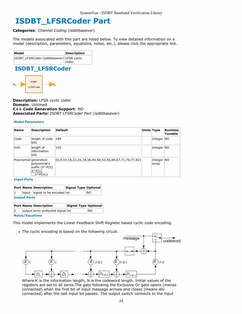
Description: LFSR cyclic coderDomain: UntimedC++ Code Generation Support: NOAssociated Parts: ISDBT LFSRCoder Part (isdbtbasever)
Model Parameters
Name Description Default Units Type RuntimeTunable
Code length of codebits
184 Integer NO
Info length ofinformationbits
102 Integer NO
Polynomial generationpolynomial'ssuffix (X^P[0]X^P[1]...X^P[m])
[0,4,10,18,22,24,34,36,40,48,52,56,66,67,71,76,77,82] Integerarray
NO
Input Ports
Port Name Description Signal Type Optional
1 input signal to be encoded int NO
Output Ports
Port Name Description Signal Type Optional
2 output error protected signal int NO
Notes/Equations
This model implements the Linear Feedback Shift Register based cyclic code encoding.
The cyclic encoding is based on the following circuit.
Where K is the information length, N is the codeword length. Initial values of theregisters are set to all zeros.The gate following the Exclusive Or gate opens (menasconnected) when the first bit of input message arrives and closes (means dis-connected) after the last input bit passes. The output switch connects to the input
SystemVue - ISDBT Baseband Verification Library
25
message when the the first bit of input message arrives and connects to the outputof DN-K-1 after the last input bit passes. gi, binary 0 or 1, is the coefficient of
generation polynomial, and g0 and gN-K should always be 1.
If the code generation polynomial is g(x) = x10 + x9 + x5 + x4 + x + 1, i.e.g([10:0]) = [1,1,0,0,0,1,1,0,0,1,1], the Polynomial parameter should be set as[0,1,4,5,9,10] (the degree of x's term whose coefficient is 1).
References
SystemVue - ISDBT Baseband Verification Library
26
ISDBT_PNGenerator PartCategories: Channel Coding (isdbtbasever)
The models associated with this part are listed below. To view detailed information on amodel (description, parameters, equations, notes, etc.), please click the appropriate link.
Model Description
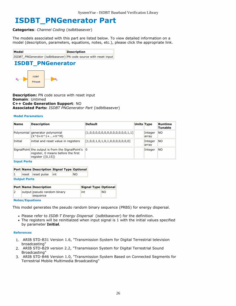
ISDBT_PNGenerator (isdbtbasever) PN code source with reset input
ISDBT_PNGenerator
Description: PN code source with reset inputDomain: UntimedC++ Code Generation Support: NOAssociated Parts: ISDBT PNGenerator Part (isdbtbasever)
Model Parameters
Name Description Default Units Type RuntimeTunable
Polynomial generator polynomial(X^0+X^1+...+X^M)
[1,0,0,0,0,0,0,0,0,0,0,0,0,0,1,1] Integerarray
NO
Initial initial and reset value in registers [1,0,0,1,0,1,0,1,0,0,0,0,0,0,0] Integerarray
NO
SignalPoint the output is from the SignalPoint'sregister, 0 means before the firstregister ([0,15])
0 Integer NO
Input Ports
Port Name Description Signal Type Optional
1 reset reset pulse int NO
Output Ports
Port Name Description Signal Type Optional
2 output pseudo random binarysequence
int NO
Notes/Equations
This model generates the pseudo random binary sequence (PRBS) for energy dispersal.
Please refer to ISDB-T Energy Dispersal (isdbtbasever) for the definition.The registers will be reinitialzed when input signal is 1 with the initial values specifiedby parameter Initial.
References
ARIB STD-B31 Version 1.6, "Transmission System for Digital Terrestrial television1.broadcasting" ARIB STD-B29 version 2.2, "Transmission System for Digital Terrestrial Sound2.Broadcasting" ARIB STD-B46 Version 1.0, "Transmission System Based on Connected Segments for3.Terrestrial Mobile Multimedia Broadcasting"
SystemVue - ISDBT Baseband Verification Library
27
ISDBT_PuncCoder PartCategories: Channel Coding (isdbtbasever)
The models associated with this part are listed below. To view detailed information on amodel (description, parameters, equations, notes, etc.), please click the appropriate link.
Model Description
ISDBT_PuncCoder (isdbtbasever) Puncturer for convolutional coder
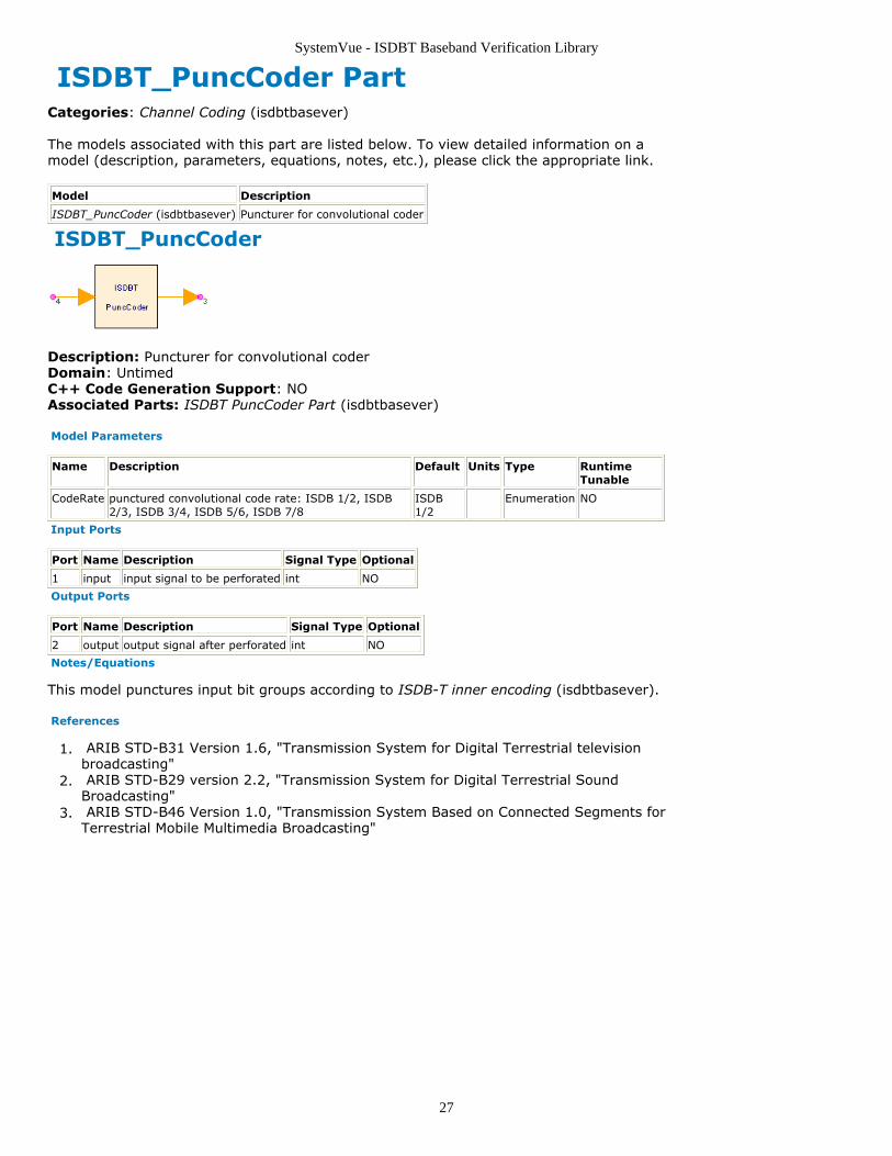
ISDBT_PuncCoder
Description: Puncturer for convolutional coderDomain: UntimedC++ Code Generation Support: NOAssociated Parts: ISDBT PuncCoder Part (isdbtbasever)
Model Parameters
Name Description Default Units Type RuntimeTunable
CodeRate punctured convolutional code rate: ISDB 1/2, ISDB2/3, ISDB 3/4, ISDB 5/6, ISDB 7/8
ISDB1/2
Enumeration NO
Input Ports
Port Name Description Signal Type Optional
1 input input signal to be perforated int NO
Output Ports
Port Name Description Signal Type Optional
2 output output signal after perforated int NO
Notes/Equations
This model punctures input bit groups according to ISDB-T inner encoding (isdbtbasever).
References
ARIB STD-B31 Version 1.6, "Transmission System for Digital Terrestrial television1.broadcasting" ARIB STD-B29 version 2.2, "Transmission System for Digital Terrestrial Sound2.Broadcasting" ARIB STD-B46 Version 1.0, "Transmission System Based on Connected Segments for3.Terrestrial Mobile Multimedia Broadcasting"
SystemVue - ISDBT Baseband Verification Library
28
ISDBT_PuncDecoder PartCategories: Channel Coding (isdbtbasever)
The models associated with this part are listed below. To view detailed information on amodel (description, parameters, equations, notes, etc.), please click the appropriate link.
Model Description
ISDBT_PuncDecoder (isdbtbasever) Puncture decoder
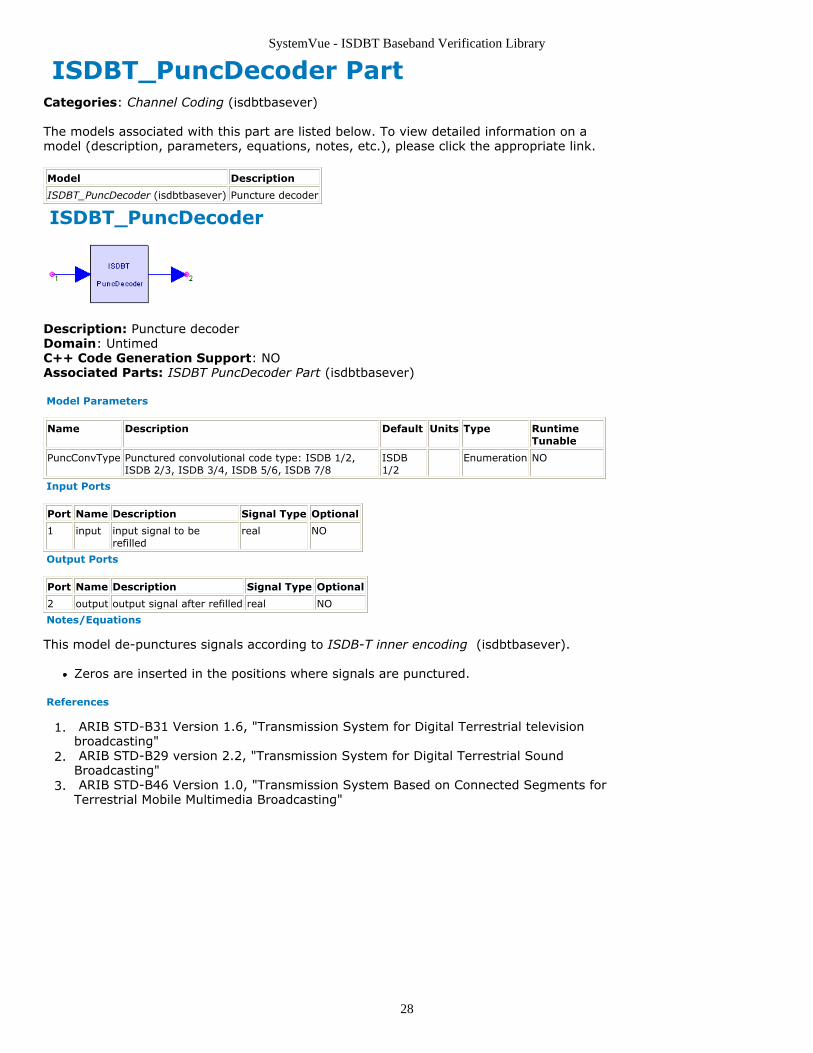
ISDBT_PuncDecoder
Description: Puncture decoderDomain: UntimedC++ Code Generation Support: NOAssociated Parts: ISDBT PuncDecoder Part (isdbtbasever)
Model Parameters
Name Description Default Units Type RuntimeTunable
PuncConvType Punctured convolutional code type: ISDB 1/2,ISDB 2/3, ISDB 3/4, ISDB 5/6, ISDB 7/8
ISDB1/2
Enumeration NO
Input Ports
Port Name Description Signal Type Optional
1 input input signal to berefilled
real NO
Output Ports
Port Name Description Signal Type Optional
2 output output signal after refilled real NO
Notes/Equations
This model de-punctures signals according to ISDB-T inner encoding (isdbtbasever).
Zeros are inserted in the positions where signals are punctured.
References
ARIB STD-B31 Version 1.6, "Transmission System for Digital Terrestrial television1.broadcasting" ARIB STD-B29 version 2.2, "Transmission System for Digital Terrestrial Sound2.Broadcasting" ARIB STD-B46 Version 1.0, "Transmission System Based on Connected Segments for3.Terrestrial Mobile Multimedia Broadcasting"
SystemVue - ISDBT Baseband Verification Library
29
ISDBT_Randomize Part ISDBT-T energy randomization of tansmission stream packages
Categories: Channel Coding (isdbtbasever)
The models associated with this part are listed below. To view detailed information on amodel (description, parameters, equations, notes, etc.), please click the appropriate link.
Model
ISDBT_Randomize (isdbtbasever)
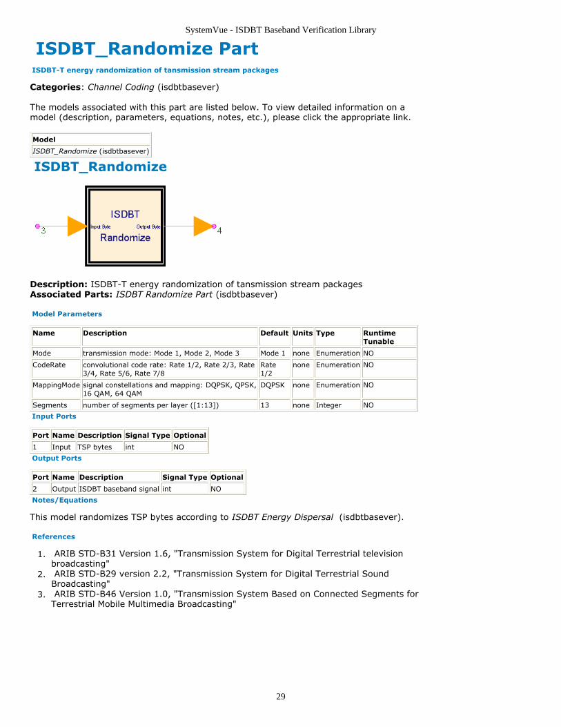
ISDBT_Randomize
Description: ISDBT-T energy randomization of tansmission stream packagesAssociated Parts: ISDBT Randomize Part (isdbtbasever)
Model Parameters
Name Description Default Units Type RuntimeTunable
Mode transmission mode: Mode 1, Mode 2, Mode 3 Mode 1 none Enumeration NO
CodeRate convolutional code rate: Rate 1/2, Rate 2/3, Rate3/4, Rate 5/6, Rate 7/8
Rate1/2
none Enumeration NO
MappingMode signal constellations and mapping: DQPSK, QPSK,16 QAM, 64 QAM
DQPSK none Enumeration NO
Segments number of segments per layer ([1:13]) 13 none Integer NO
Input Ports
Port Name Description Signal Type Optional
1 Input TSP bytes int NO
Output Ports
Port Name Description Signal Type Optional
2 Output ISDBT baseband signal int NO
Notes/Equations
This model randomizes TSP bytes according to ISDBT Energy Dispersal (isdbtbasever).
References
ARIB STD-B31 Version 1.6, "Transmission System for Digital Terrestrial television1.broadcasting" ARIB STD-B29 version 2.2, "Transmission System for Digital Terrestrial Sound2.Broadcasting" ARIB STD-B46 Version 1.0, "Transmission System Based on Connected Segments for3.Terrestrial Mobile Multimedia Broadcasting"

SystemVue - ISDBT Baseband Verification Library
30
ISDBT Interleaving Category Contents
ISDBT CarrierRotator Part (isdbtbasever)ISDBT CarrierScrambler Part (isdbtbasever)ISDBT FreqDeinterlv Part (isdbtbasever)ISDBT FreqInterlv Part (isdbtbasever)ISDBT InterlvFloat Part (isdbtbasever)ISDBT InterlvInt Part (isdbtbasever)ISDBT InterSegInterlv Part (isdbtbasever)ISDBT TimeInterlv Part (isdbtbasever)ISDBT TimeInterlvDelay Part (isdbtbasever)ISDBT TwoLayFreqDeinterlv Part (isdbtbasever)ISDBT TwoLayFreqInterlv Part (isdbtbasever)
SystemVue - ISDBT Baseband Verification Library
31
ISDBT_CarrierRotator PartCategories: Interleaving (isdbtbasever)
The models associated with this part are listed below. To view detailed information on amodel (description, parameters, equations, notes, etc.), please click the appropriate link.
Model Description
ISDBT_CarrierRotator (isdbtbasever) Particle rotation within segment
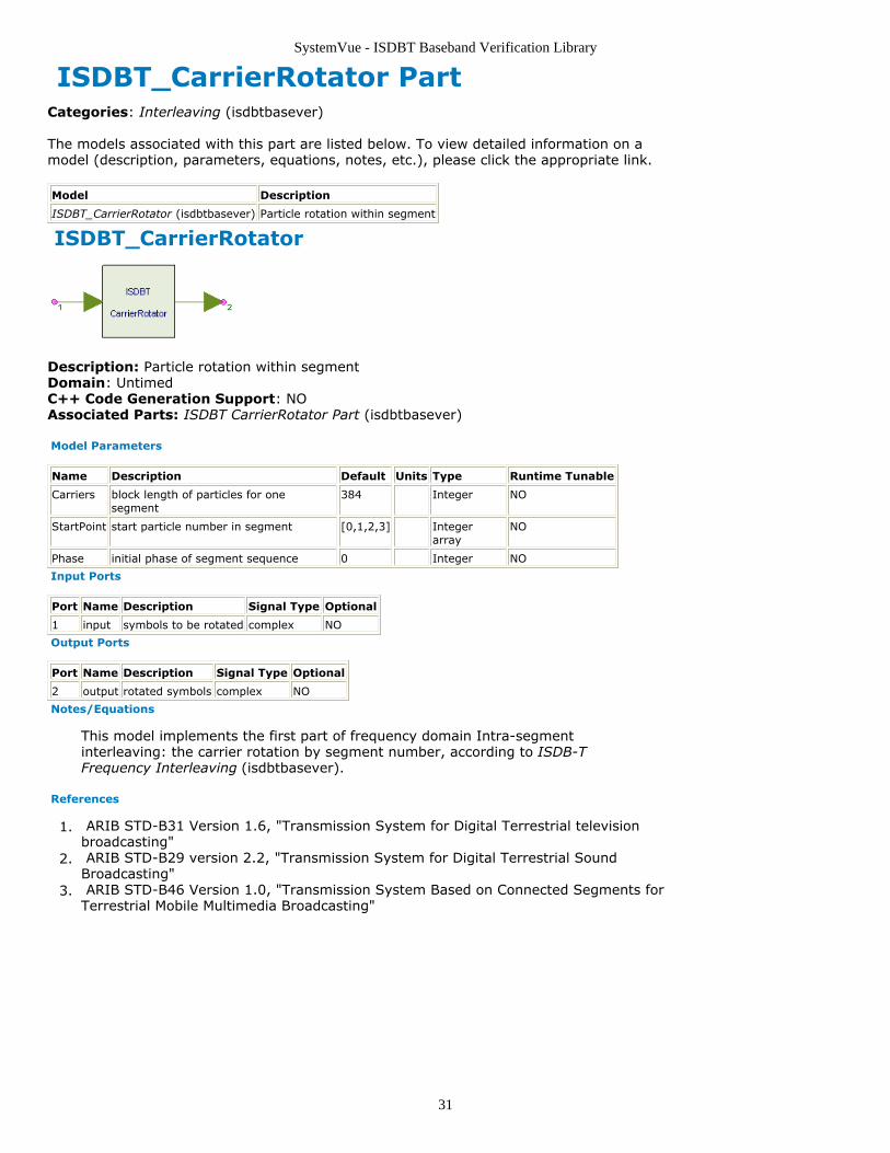
ISDBT_CarrierRotator
Description: Particle rotation within segmentDomain: UntimedC++ Code Generation Support: NOAssociated Parts: ISDBT CarrierRotator Part (isdbtbasever)
Model Parameters
Name Description Default Units Type Runtime Tunable
Carriers block length of particles for onesegment
384 Integer NO
StartPoint start particle number in segment [0,1,2,3] Integerarray
NO
Phase initial phase of segment sequence 0 Integer NO
Input Ports
Port Name Description Signal Type Optional
1 input symbols to be rotated complex NO
Output Ports
Port Name Description Signal Type Optional
2 output rotated symbols complex NO
Notes/Equations
This model implements the first part of frequency domain Intra-segmentinterleaving: the carrier rotation by segment number, according to ISDB-TFrequency Interleaving (isdbtbasever).
References
ARIB STD-B31 Version 1.6, "Transmission System for Digital Terrestrial television1.broadcasting" ARIB STD-B29 version 2.2, "Transmission System for Digital Terrestrial Sound2.Broadcasting" ARIB STD-B46 Version 1.0, "Transmission System Based on Connected Segments for3.Terrestrial Mobile Multimedia Broadcasting"
SystemVue - ISDBT Baseband Verification Library
32
ISDBT_CarrierScrambler PartCategories: Interleaving (isdbtbasever)
The models associated with this part are listed below. To view detailed information on amodel (description, parameters, equations, notes, etc.), please click the appropriate link.
Model Description
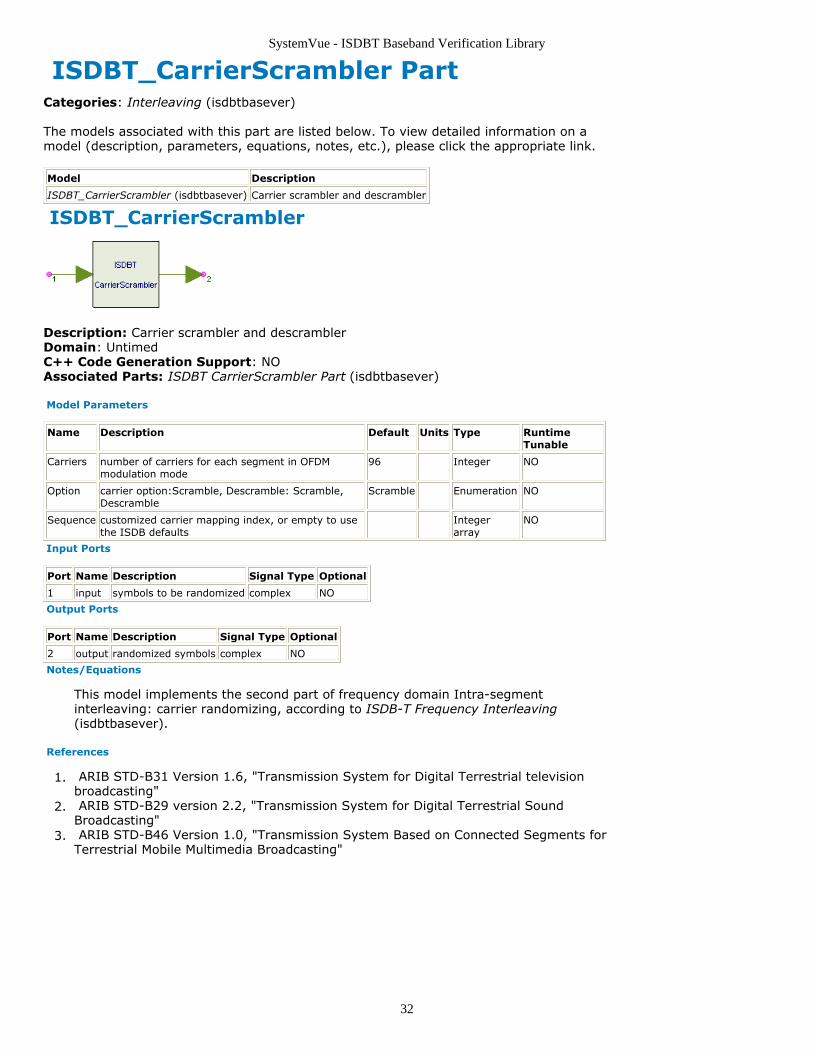
ISDBT_CarrierScrambler (isdbtbasever) Carrier scrambler and descrambler
ISDBT_CarrierScrambler
Description: Carrier scrambler and descramblerDomain: UntimedC++ Code Generation Support: NOAssociated Parts: ISDBT CarrierScrambler Part (isdbtbasever)
Model Parameters
Name Description Default Units Type RuntimeTunable
Carriers number of carriers for each segment in OFDMmodulation mode
96 Integer NO
Option carrier option:Scramble, Descramble: Scramble,Descramble
Scramble Enumeration NO
Sequence customized carrier mapping index, or empty to usethe ISDB defaults
Integerarray
NO
Input Ports
Port Name Description Signal Type Optional
1 input symbols to be randomized complex NO
Output Ports
Port Name Description Signal Type Optional
2 output randomized symbols complex NO
Notes/Equations
This model implements the second part of frequency domain Intra-segmentinterleaving: carrier randomizing, according to ISDB-T Frequency Interleaving(isdbtbasever).
References
ARIB STD-B31 Version 1.6, "Transmission System for Digital Terrestrial television1.broadcasting" ARIB STD-B29 version 2.2, "Transmission System for Digital Terrestrial Sound2.Broadcasting" ARIB STD-B46 Version 1.0, "Transmission System Based on Connected Segments for3.Terrestrial Mobile Multimedia Broadcasting"
SystemVue - ISDBT Baseband Verification Library
33
ISDBT_FreqDeinterlv Part Inter-frequency and intra-frequency deinterleaving for ISDBT-T
Categories: Interleaving (isdbtbasever)
The models associated with this part are listed below. To view detailed information on amodel (description, parameters, equations, notes, etc.), please click the appropriate link.
Model
ISDBT_FreqDeinterlv (isdbtbasever)
ISDBT_FreqDeinterlv
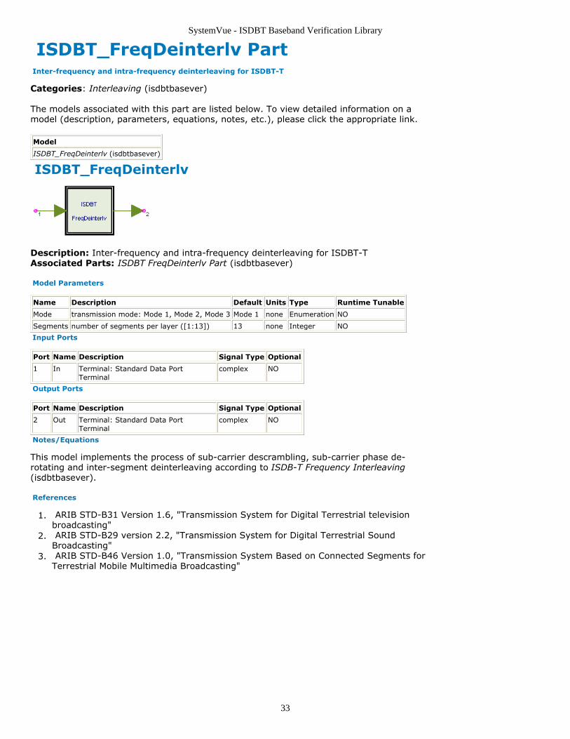
Description: Inter-frequency and intra-frequency deinterleaving for ISDBT-TAssociated Parts: ISDBT FreqDeinterlv Part (isdbtbasever)
Model Parameters
Name Description Default Units Type Runtime Tunable
Mode transmission mode: Mode 1, Mode 2, Mode 3 Mode 1 none Enumeration NO
Segments number of segments per layer ([1:13]) 13 none Integer NO
Input Ports
Port Name Description Signal Type Optional
1 In Terminal: Standard Data PortTerminal
complex NO
Output Ports
Port Name Description Signal Type Optional
2 Out Terminal: Standard Data PortTerminal
complex NO
Notes/Equations
This model implements the process of sub-carrier descrambling, sub-carrier phase de-rotating and inter-segment deinterleaving according to ISDB-T Frequency Interleaving(isdbtbasever).
References
ARIB STD-B31 Version 1.6, "Transmission System for Digital Terrestrial television1.broadcasting" ARIB STD-B29 version 2.2, "Transmission System for Digital Terrestrial Sound2.Broadcasting" ARIB STD-B46 Version 1.0, "Transmission System Based on Connected Segments for3.Terrestrial Mobile Multimedia Broadcasting"
SystemVue - ISDBT Baseband Verification Library
34
ISDBT_FreqInterlv Part Inter-frequency and intra-frequency interleaving for ISDBT-T
Categories: Interleaving (isdbtbasever)
The models associated with this part are listed below. To view detailed information on amodel (description, parameters, equations, notes, etc.), please click the appropriate link.
Model
ISDBT_FreqInterlv (isdbtbasever)
ISDBT_FreqInterlv
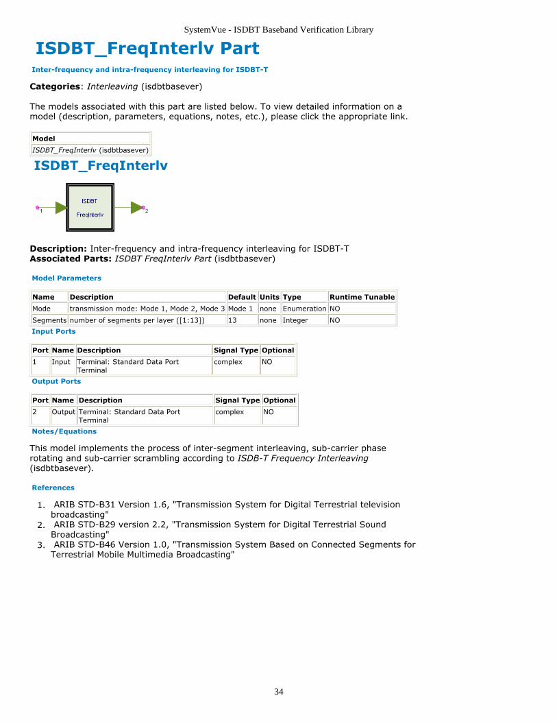
Description: Inter-frequency and intra-frequency interleaving for ISDBT-TAssociated Parts: ISDBT FreqInterlv Part (isdbtbasever)
Model Parameters
Name Description Default Units Type Runtime Tunable
Mode transmission mode: Mode 1, Mode 2, Mode 3 Mode 1 none Enumeration NO
Segments number of segments per layer ([1:13]) 13 none Integer NO
Input Ports
Port Name Description Signal Type Optional
1 Input Terminal: Standard Data PortTerminal
complex NO
Output Ports
Port Name Description Signal Type Optional
2 Output Terminal: Standard Data PortTerminal
complex NO
Notes/Equations
This model implements the process of inter-segment interleaving, sub-carrier phaserotating and sub-carrier scrambling according to ISDB-T Frequency Interleaving(isdbtbasever).
References
ARIB STD-B31 Version 1.6, "Transmission System for Digital Terrestrial television1.broadcasting" ARIB STD-B29 version 2.2, "Transmission System for Digital Terrestrial Sound2.Broadcasting" ARIB STD-B46 Version 1.0, "Transmission System Based on Connected Segments for3.Terrestrial Mobile Multimedia Broadcasting"
SystemVue - ISDBT Baseband Verification Library
35
ISDBT_InterlvFloat PartCategories: Interleaving (isdbtbasever)
The models associated with this part are listed below. To view detailed information on amodel (description, parameters, equations, notes, etc.), please click the appropriate link.
Model Description
ISDBT_InterlvFloat (isdbtbasever) Interleaver and de-interleaver for float
ISDBT_InterlvFloat
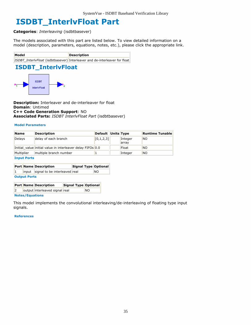
Description: Interleaver and de-interleaver for floatDomain: UntimedC++ Code Generation Support: NOAssociated Parts: ISDBT InterlvFloat Part (isdbtbasever)
Model Parameters
Name Description Default Units Type Runtime Tunable
Delays delay of each branch [0,1,2,3] Integerarray
NO
Initial_value initial value in interleaver delay FIFOs 0.0 Float NO
Multiplier multiple branch number 1 Integer NO
Input Ports
Port Name Description Signal Type Optional
1 input signal to be interleaved real NO
Output Ports
Port Name Description Signal Type Optional
2 output interleaved signal real NO
Notes/Equations
This model implements the convolutional interleaving/de-interleaving of floating type inputsignals.
References
SystemVue - ISDBT Baseband Verification Library
36
ISDBT_InterlvInt PartCategories: Interleaving (isdbtbasever)
The models associated with this part are listed below. To view detailed information on amodel (description, parameters, equations, notes, etc.), please click the appropriate link.
Model Description
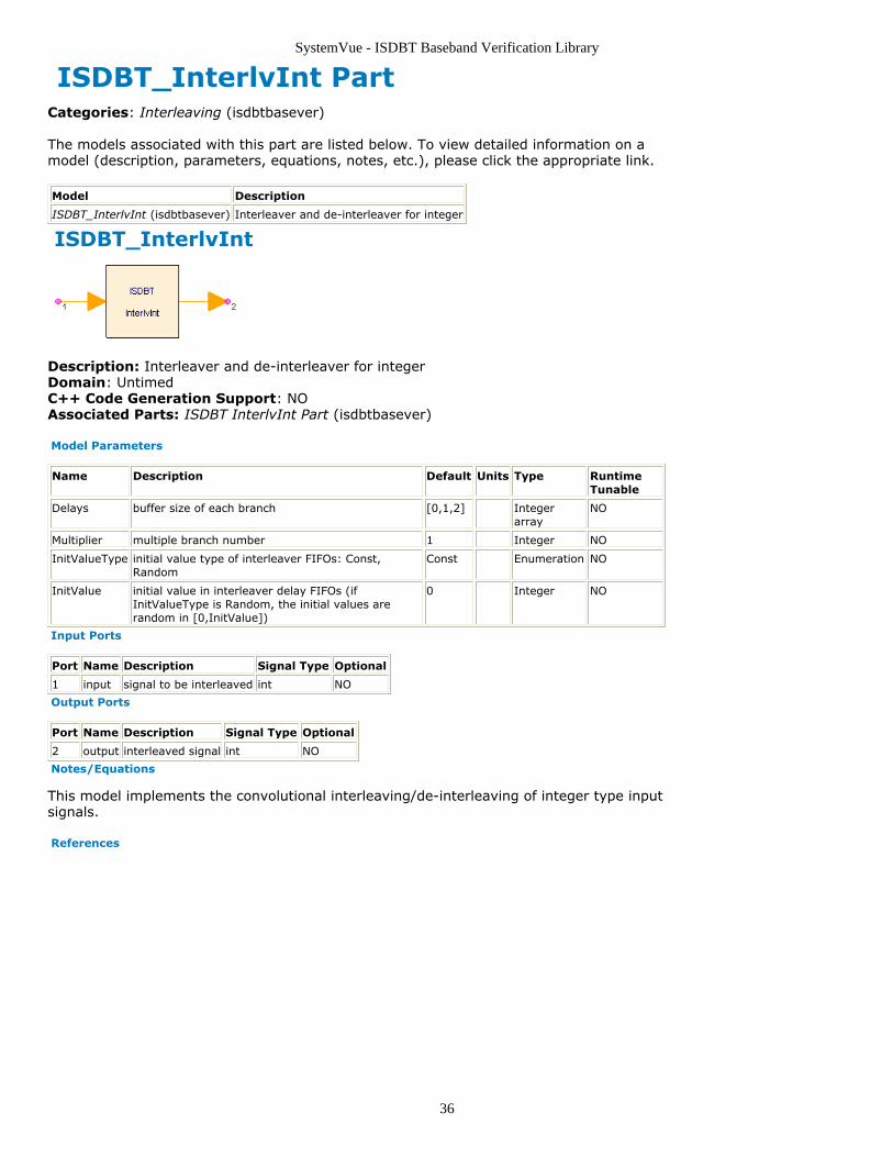
ISDBT_InterlvInt (isdbtbasever) Interleaver and de-interleaver for integer
ISDBT_InterlvInt
Description: Interleaver and de-interleaver for integerDomain: UntimedC++ Code Generation Support: NOAssociated Parts: ISDBT InterlvInt Part (isdbtbasever)
Model Parameters
Name Description Default Units Type RuntimeTunable
Delays buffer size of each branch [0,1,2] Integerarray
NO
Multiplier multiple branch number 1 Integer NO
InitValueType initial value type of interleaver FIFOs: Const,Random
Const Enumeration NO
InitValue initial value in interleaver delay FIFOs (ifInitValueType is Random, the initial values arerandom in [0,InitValue])
0 Integer NO
Input Ports
Port Name Description Signal Type Optional
1 input signal to be interleaved int NO
Output Ports
Port Name Description Signal Type Optional
2 output interleaved signal int NO
Notes/Equations
This model implements the convolutional interleaving/de-interleaving of integer type inputsignals.
References
SystemVue - ISDBT Baseband Verification Library
37
ISDBT_InterSegInterlv PartCategories: Interleaving (isdbtbasever)
The models associated with this part are listed below. To view detailed information on amodel (description, parameters, equations, notes, etc.), please click the appropriate link.
Model Description
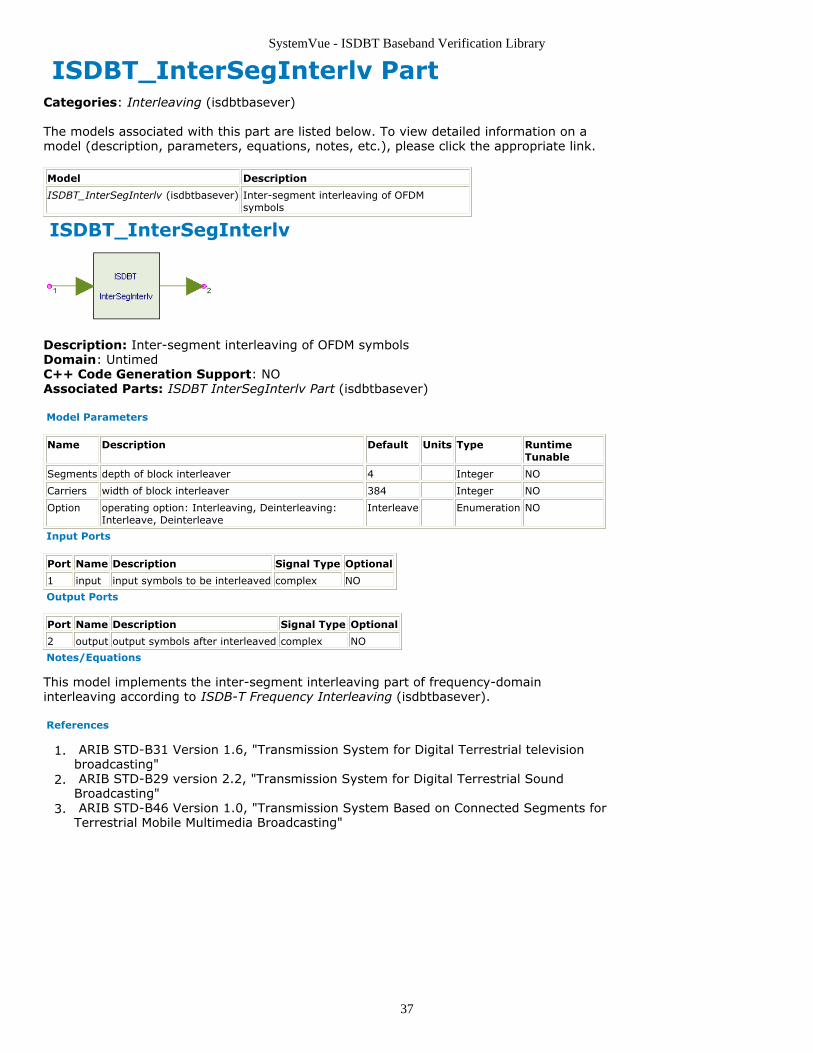
ISDBT_InterSegInterlv (isdbtbasever) Inter-segment interleaving of OFDMsymbols
ISDBT_InterSegInterlv
Description: Inter-segment interleaving of OFDM symbolsDomain: UntimedC++ Code Generation Support: NOAssociated Parts: ISDBT InterSegInterlv Part (isdbtbasever)
Model Parameters
Name Description Default Units Type RuntimeTunable
Segments depth of block interleaver 4 Integer NO
Carriers width of block interleaver 384 Integer NO
Option operating option: Interleaving, Deinterleaving:Interleave, Deinterleave
Interleave Enumeration NO
Input Ports
Port Name Description Signal Type Optional
1 input input symbols to be interleaved complex NO
Output Ports
Port Name Description Signal Type Optional
2 output output symbols after interleaved complex NO
Notes/Equations
This model implements the inter-segment interleaving part of frequency-domaininterleaving according to ISDB-T Frequency Interleaving (isdbtbasever).
References
ARIB STD-B31 Version 1.6, "Transmission System for Digital Terrestrial television1.broadcasting" ARIB STD-B29 version 2.2, "Transmission System for Digital Terrestrial Sound2.Broadcasting" ARIB STD-B46 Version 1.0, "Transmission System Based on Connected Segments for3.Terrestrial Mobile Multimedia Broadcasting"
SystemVue - ISDBT Baseband Verification Library
38
ISDBT_TimeInterlvDelay Part ISDBT-T intra-segment time interleaver
Categories: Interleaving (isdbtbasever)
The models associated with this part are listed below. To view detailed information on amodel (description, parameters, equations, notes, etc.), please click the appropriate link.
Model
ISDBT_TimeInterlvDelay (isdbtbasever)
ISDBT_TimeInterlvDelay
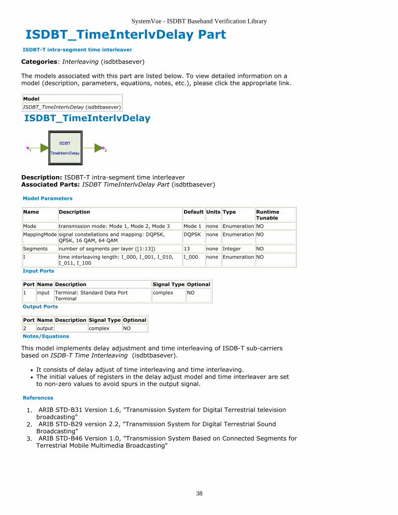
Description: ISDBT-T intra-segment time interleaverAssociated Parts: ISDBT TimeInterlvDelay Part (isdbtbasever)
Model Parameters
Name Description Default Units Type RuntimeTunable
Mode transmission mode: Mode 1, Mode 2, Mode 3 Mode 1 none Enumeration NO
MappingMode signal constellations and mapping: DQPSK,QPSK, 16 QAM, 64 QAM
DQPSK none Enumeration NO
Segments number of segments per layer ([1:13]) 13 none Integer NO
I time interleaving length: I_000, I_001, I_010,I_011, I_100
I_000 none Enumeration NO
Input Ports
Port Name Description Signal Type Optional
1 input Terminal: Standard Data PortTerminal
complex NO
Output Ports
Port Name Description Signal Type Optional
2 output complex NO
Notes/Equations
This model implements delay adjustment and time interleaving of ISDB-T sub-carriersbased on ISDB-T Time Interleaving (isdbtbasever).
It consists of delay adjust of time interleaving and time interleaving.The initial values of registers in the delay adjust model and time interleaver are setto non-zero values to avoid spurs in the output signal.
References
ARIB STD-B31 Version 1.6, "Transmission System for Digital Terrestrial television1.broadcasting" ARIB STD-B29 version 2.2, "Transmission System for Digital Terrestrial Sound2.Broadcasting" ARIB STD-B46 Version 1.0, "Transmission System Based on Connected Segments for3.Terrestrial Mobile Multimedia Broadcasting"
SystemVue - ISDBT Baseband Verification Library
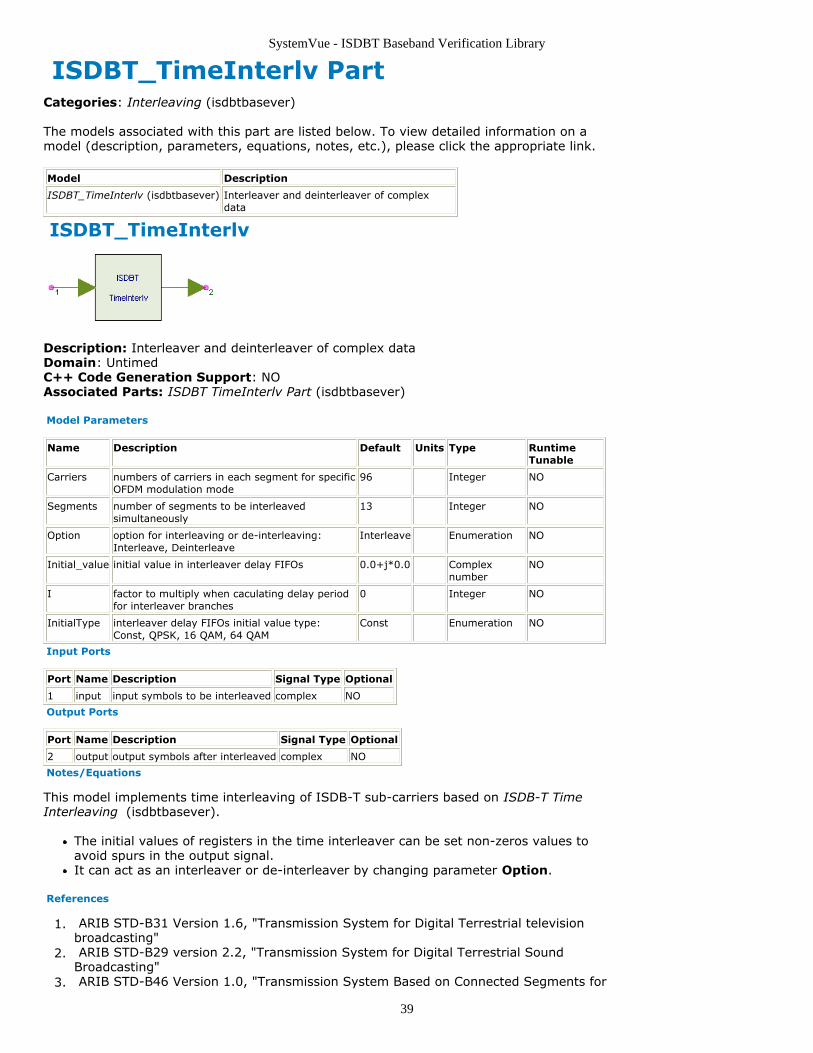
39
ISDBT_TimeInterlv PartCategories: Interleaving (isdbtbasever)
The models associated with this part are listed below. To view detailed information on amodel (description, parameters, equations, notes, etc.), please click the appropriate link.
Model Description
ISDBT_TimeInterlv (isdbtbasever) Interleaver and deinterleaver of complexdata
ISDBT_TimeInterlv
Description: Interleaver and deinterleaver of complex dataDomain: UntimedC++ Code Generation Support: NOAssociated Parts: ISDBT TimeInterlv Part (isdbtbasever)
Model Parameters
Name Description Default Units Type RuntimeTunable
Carriers numbers of carriers in each segment for specificOFDM modulation mode
96 Integer NO
Segments number of segments to be interleavedsimultaneously
13 Integer NO
Option option for interleaving or de-interleaving:Interleave, Deinterleave
Interleave Enumeration NO
Initial_value initial value in interleaver delay FIFOs 0.0+j*0.0 Complexnumber
NO
I factor to multiply when caculating delay periodfor interleaver branches
0 Integer NO
InitialType interleaver delay FIFOs initial value type:Const, QPSK, 16 QAM, 64 QAM
Const Enumeration NO
Input Ports
Port Name Description Signal Type Optional
1 input input symbols to be interleaved complex NO
Output Ports
Port Name Description Signal Type Optional
2 output output symbols after interleaved complex NO
Notes/Equations
This model implements time interleaving of ISDB-T sub-carriers based on ISDB-T TimeInterleaving (isdbtbasever).
The initial values of registers in the time interleaver can be set non-zeros values toavoid spurs in the output signal.It can act as an interleaver or de-interleaver by changing parameter Option.
References
ARIB STD-B31 Version 1.6, "Transmission System for Digital Terrestrial television1.broadcasting" ARIB STD-B29 version 2.2, "Transmission System for Digital Terrestrial Sound2.Broadcasting" ARIB STD-B46 Version 1.0, "Transmission System Based on Connected Segments for3.

SystemVue - ISDBT Baseband Verification Library
40
Terrestrial Mobile Multimedia Broadcasting"
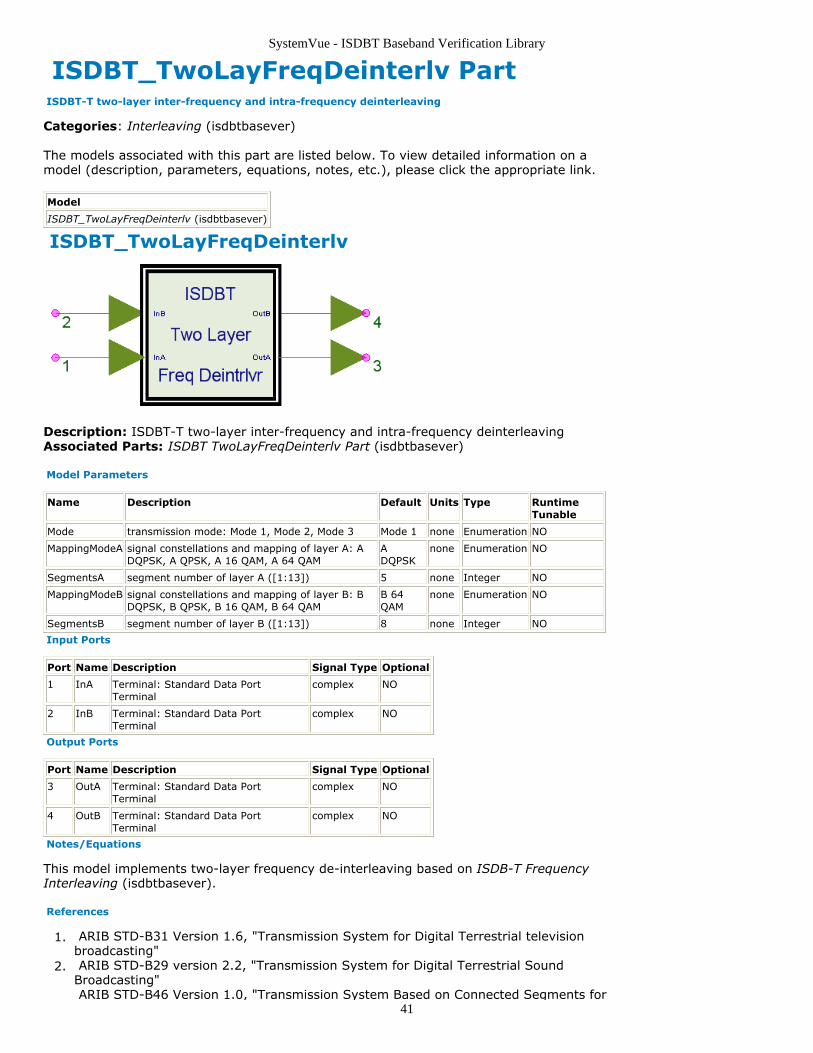
SystemVue - ISDBT Baseband Verification Library
41
ISDBT_TwoLayFreqDeinterlv Part ISDBT-T two-layer inter-frequency and intra-frequency deinterleaving
Categories: Interleaving (isdbtbasever)
The models associated with this part are listed below. To view detailed information on amodel (description, parameters, equations, notes, etc.), please click the appropriate link.
Model
ISDBT_TwoLayFreqDeinterlv (isdbtbasever)
ISDBT_TwoLayFreqDeinterlv
Description: ISDBT-T two-layer inter-frequency and intra-frequency deinterleavingAssociated Parts: ISDBT TwoLayFreqDeinterlv Part (isdbtbasever)
Model Parameters
Name Description Default Units Type RuntimeTunable
Mode transmission mode: Mode 1, Mode 2, Mode 3 Mode 1 none Enumeration NO
MappingModeA signal constellations and mapping of layer A: ADQPSK, A QPSK, A 16 QAM, A 64 QAM
ADQPSK
none Enumeration NO
SegmentsA segment number of layer A ([1:13]) 5 none Integer NO
MappingModeB signal constellations and mapping of layer B: BDQPSK, B QPSK, B 16 QAM, B 64 QAM
B 64QAM
none Enumeration NO
SegmentsB segment number of layer B ([1:13]) 8 none Integer NO
Input Ports
Port Name Description Signal Type Optional
1 InA Terminal: Standard Data PortTerminal
complex NO
2 InB Terminal: Standard Data PortTerminal
complex NO
Output Ports
Port Name Description Signal Type Optional
3 OutA Terminal: Standard Data PortTerminal
complex NO
4 OutB Terminal: Standard Data PortTerminal
complex NO
Notes/Equations
This model implements two-layer frequency de-interleaving based on ISDB-T FrequencyInterleaving (isdbtbasever).
References
ARIB STD-B31 Version 1.6, "Transmission System for Digital Terrestrial television1.broadcasting" ARIB STD-B29 version 2.2, "Transmission System for Digital Terrestrial Sound2.Broadcasting" ARIB STD-B46 Version 1.0, "Transmission System Based on Connected Segments for
SystemVue - ISDBT Baseband Verification Library
42
3.Terrestrial Mobile Multimedia Broadcasting"
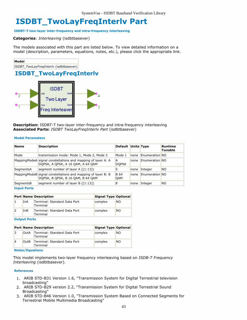
SystemVue - ISDBT Baseband Verification Library
43
ISDBT_TwoLayFreqInterlv Part ISDBT-T two-layer inter-frequency and intra-frequency interleaving
Categories: Interleaving (isdbtbasever)
The models associated with this part are listed below. To view detailed information on amodel (description, parameters, equations, notes, etc.), please click the appropriate link.
Model
ISDBT_TwoLayFreqInterlv (isdbtbasever)
ISDBT_TwoLayFreqInterlv
Description: ISDBT-T two-layer inter-frequency and intra-frequency interleavingAssociated Parts: ISDBT TwoLayFreqInterlv Part (isdbtbasever)
Model Parameters
Name Description Default Units Type RuntimeTunable
Mode transmission mode: Mode 1, Mode 2, Mode 3 Mode 1 none Enumeration NO
MappingModeA signal constellations and mapping of layer A: ADQPSK, A QPSK, A 16 QAM, A 64 QAM
ADQPSK
none Enumeration NO
SegmentsA segment number of layer A ([1:13]) 5 none Integer NO
MappingModeB signal constellations and mapping of layer B: BDQPSK, B QPSK, B 16 QAM, B 64 QAM
B 64QAM
none Enumeration NO
SegmentsB segment number of layer B ([1:13]) 8 none Integer NO
Input Ports
Port Name Description Signal Type Optional
1 InA Terminal: Standard Data PortTerminal
complex NO
2 InB Terminal: Standard Data PortTerminal
complex NO
Output Ports
Port Name Description Signal Type Optional
3 OutA Terminal: Standard Data PortTerminal
complex NO
4 OutB Terminal: Standard Data PortTerminal
complex NO
Notes/Equations
This model implements two-layer frequency interleaving based on ISDB-T FrequencyInterleaving (isdbtbasever).
References
ARIB STD-B31 Version 1.6, "Transmission System for Digital Terrestrial television1.broadcasting" ARIB STD-B29 version 2.2, "Transmission System for Digital Terrestrial Sound2.Broadcasting" ARIB STD-B46 Version 1.0, "Transmission System Based on Connected Segments for3.Terrestrial Mobile Multimedia Broadcasting"
SystemVue - ISDBT Baseband Verification Library
44
ISDBT Modulation Category Contents
ISDBT CFRNorm Part (isdbtbasever)ISDBT Demapper Part (isdbtbasever)ISDBT Demodulation Part (isdbtbasever)ISDBT DQPSKCoder Part (isdbtbasever)ISDBT DQPSKDecoder Part (isdbtbasever)ISDBT Mapper Part (isdbtbasever)ISDBT Modulation Part (isdbtbasever)ISDBT TMCCDemod Part (isdbtbasever)ISDBT TMCCMod Part (isdbtbasever)
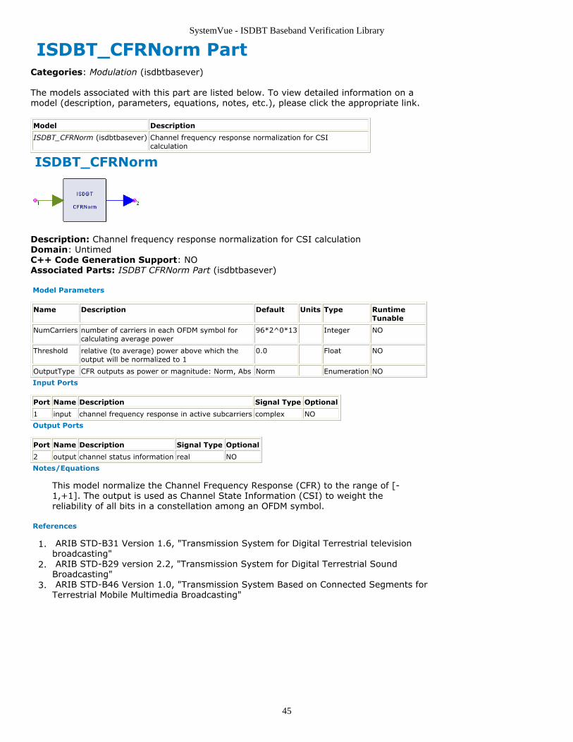
SystemVue - ISDBT Baseband Verification Library
45
ISDBT_CFRNorm PartCategories: Modulation (isdbtbasever)
The models associated with this part are listed below. To view detailed information on amodel (description, parameters, equations, notes, etc.), please click the appropriate link.
Model Description
ISDBT_CFRNorm (isdbtbasever) Channel frequency response normalization for CSIcalculation
ISDBT_CFRNorm
Description: Channel frequency response normalization for CSI calculationDomain: UntimedC++ Code Generation Support: NOAssociated Parts: ISDBT CFRNorm Part (isdbtbasever)
Model Parameters
Name Description Default Units Type RuntimeTunable
NumCarriers number of carriers in each OFDM symbol forcalculating average power
96*2^0*13 Integer NO
Threshold relative (to average) power above which theoutput will be normalized to 1
0.0 Float NO
OutputType CFR outputs as power or magnitude: Norm, Abs Norm Enumeration NO
Input Ports
Port Name Description Signal Type Optional
1 input channel frequency response in active subcarriers complex NO
Output Ports
Port Name Description Signal Type Optional
2 output channel status information real NO
Notes/Equations
This model normalize the Channel Frequency Response (CFR) to the range of [-1,+1]. The output is used as Channel State Information (CSI) to weight thereliability of all bits in a constellation among an OFDM symbol.
References
ARIB STD-B31 Version 1.6, "Transmission System for Digital Terrestrial television1.broadcasting" ARIB STD-B29 version 2.2, "Transmission System for Digital Terrestrial Sound2.Broadcasting" ARIB STD-B46 Version 1.0, "Transmission System Based on Connected Segments for3.Terrestrial Mobile Multimedia Broadcasting"
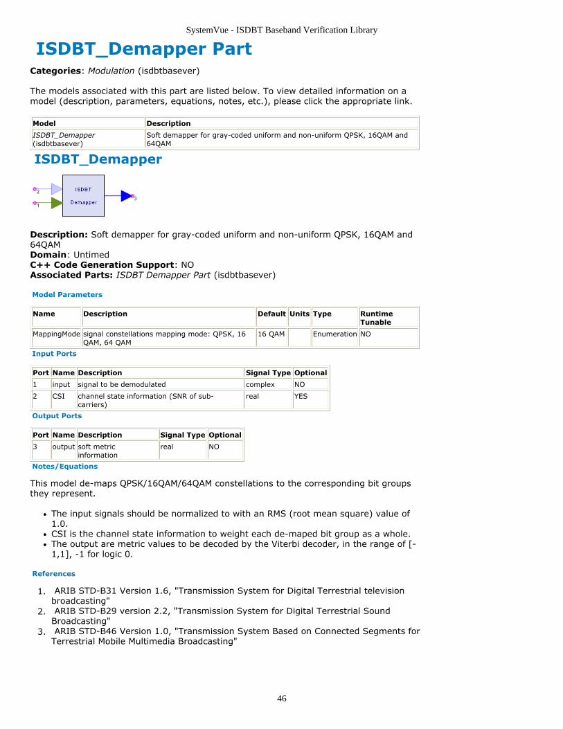
SystemVue - ISDBT Baseband Verification Library
46
ISDBT_Demapper PartCategories: Modulation (isdbtbasever)
The models associated with this part are listed below. To view detailed information on amodel (description, parameters, equations, notes, etc.), please click the appropriate link.
Model Description
ISDBT_Demapper(isdbtbasever)
Soft demapper for gray-coded uniform and non-uniform QPSK, 16QAM and64QAM
ISDBT_Demapper
Description: Soft demapper for gray-coded uniform and non-uniform QPSK, 16QAM and64QAMDomain: UntimedC++ Code Generation Support: NOAssociated Parts: ISDBT Demapper Part (isdbtbasever)
Model Parameters
Name Description Default Units Type RuntimeTunable
MappingMode signal constellations mapping mode: QPSK, 16QAM, 64 QAM
16 QAM Enumeration NO
Input Ports
Port Name Description Signal Type Optional
1 input signal to be demodulated complex NO
2 CSI channel state information (SNR of sub-carriers)
real YES
Output Ports
Port Name Description Signal Type Optional
3 output soft metricinformation
real NO
Notes/Equations
This model de-maps QPSK/16QAM/64QAM constellations to the corresponding bit groupsthey represent.
The input signals should be normalized to with an RMS (root mean square) value of1.0.CSI is the channel state information to weight each de-maped bit group as a whole.The output are metric values to be decoded by the Viterbi decoder, in the range of [-1,1], -1 for logic 0.
References
ARIB STD-B31 Version 1.6, "Transmission System for Digital Terrestrial television1.broadcasting" ARIB STD-B29 version 2.2, "Transmission System for Digital Terrestrial Sound2.Broadcasting" ARIB STD-B46 Version 1.0, "Transmission System Based on Connected Segments for3.Terrestrial Mobile Multimedia Broadcasting"
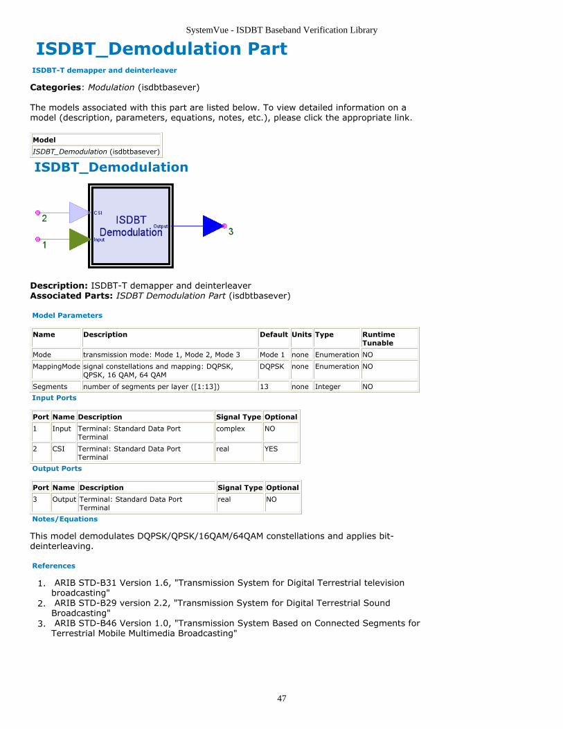
SystemVue - ISDBT Baseband Verification Library
47
ISDBT_Demodulation Part ISDBT-T demapper and deinterleaver
Categories: Modulation (isdbtbasever)
The models associated with this part are listed below. To view detailed information on amodel (description, parameters, equations, notes, etc.), please click the appropriate link.
Model
ISDBT_Demodulation (isdbtbasever)
ISDBT_Demodulation
Description: ISDBT-T demapper and deinterleaverAssociated Parts: ISDBT Demodulation Part (isdbtbasever)
Model Parameters
Name Description Default Units Type RuntimeTunable
Mode transmission mode: Mode 1, Mode 2, Mode 3 Mode 1 none Enumeration NO
MappingMode signal constellations and mapping: DQPSK,QPSK, 16 QAM, 64 QAM
DQPSK none Enumeration NO
Segments number of segments per layer ([1:13]) 13 none Integer NO
Input Ports
Port Name Description Signal Type Optional
1 Input Terminal: Standard Data PortTerminal
complex NO
2 CSI Terminal: Standard Data PortTerminal
real YES
Output Ports
Port Name Description Signal Type Optional
3 Output Terminal: Standard Data PortTerminal
real NO
Notes/Equations
This model demodulates DQPSK/QPSK/16QAM/64QAM constellations and applies bit-deinterleaving.
References
ARIB STD-B31 Version 1.6, "Transmission System for Digital Terrestrial television1.broadcasting" ARIB STD-B29 version 2.2, "Transmission System for Digital Terrestrial Sound2.Broadcasting" ARIB STD-B46 Version 1.0, "Transmission System Based on Connected Segments for3.Terrestrial Mobile Multimedia Broadcasting"
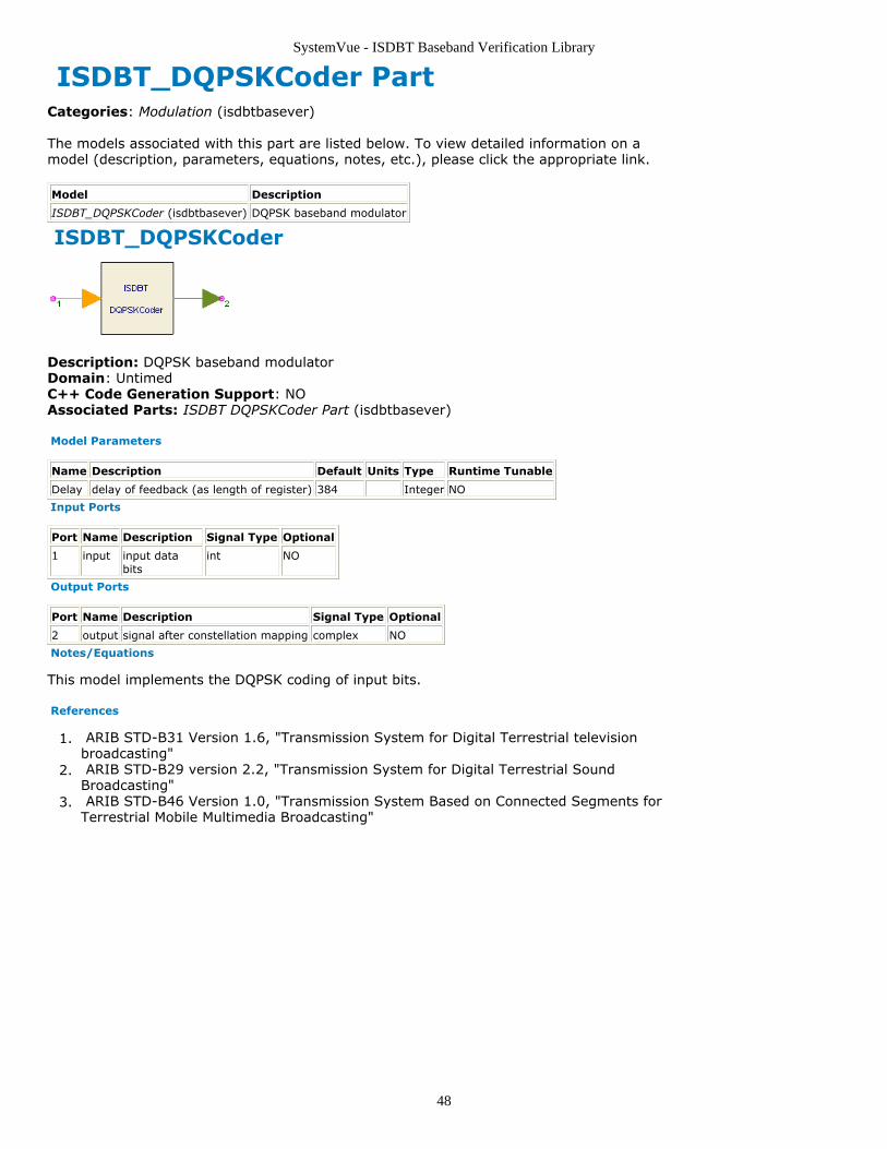
SystemVue - ISDBT Baseband Verification Library
48
ISDBT_DQPSKCoder PartCategories: Modulation (isdbtbasever)
The models associated with this part are listed below. To view detailed information on amodel (description, parameters, equations, notes, etc.), please click the appropriate link.
Model Description
ISDBT_DQPSKCoder (isdbtbasever) DQPSK baseband modulator
ISDBT_DQPSKCoder
Description: DQPSK baseband modulatorDomain: UntimedC++ Code Generation Support: NOAssociated Parts: ISDBT DQPSKCoder Part (isdbtbasever)
Model Parameters
Name Description Default Units Type Runtime Tunable
Delay delay of feedback (as length of register) 384 Integer NO
Input Ports
Port Name Description Signal Type Optional
1 input input databits
int NO
Output Ports
Port Name Description Signal Type Optional
2 output signal after constellation mapping complex NO
Notes/Equations
This model implements the DQPSK coding of input bits.
References
ARIB STD-B31 Version 1.6, "Transmission System for Digital Terrestrial television1.broadcasting" ARIB STD-B29 version 2.2, "Transmission System for Digital Terrestrial Sound2.Broadcasting" ARIB STD-B46 Version 1.0, "Transmission System Based on Connected Segments for3.Terrestrial Mobile Multimedia Broadcasting"

SystemVue - ISDBT Baseband Verification Library
49
ISDBT_DQPSKDecoder PartCategories: Modulation (isdbtbasever)
The models associated with this part are listed below. To view detailed information on amodel (description, parameters, equations, notes, etc.), please click the appropriate link.
Model Description
ISDBT_DQPSKDecoder (isdbtbasever) DQPSK decoder with soft decision
ISDBT_DQPSKDecoder
Description: DQPSK decoder with soft decisionDomain: UntimedC++ Code Generation Support: NOAssociated Parts: ISDBT DQPSKDecoder Part (isdbtbasever)
Model Parameters
Name Description Default Units Type RuntimeTunable
Delay delay of feedback (as length of register) 384 Integer NO
Renorm option to re-normalize reference phase (set to thenearest symbol point): NO, YES
NO Enumeration NO
Input Ports
Port Name Description Signal Type Optional
1 input signal to bedemodulated
complex NO
Output Ports
Port Name Description Signal Type Optional
2 output signal afterdemodulation
real NO
Notes/Equations
This model implements the DQPSK decoding of input constellations.
Outputs are metric values to be Viterbi decoded, in the range of [-1,1], -1 representslogic 0.
References
ARIB STD-B31 Version 1.6, "Transmission System for Digital Terrestrial television1.broadcasting" ARIB STD-B29 version 2.2, "Transmission System for Digital Terrestrial Sound2.Broadcasting" ARIB STD-B46 Version 1.0, "Transmission System Based on Connected Segments for3.Terrestrial Mobile Multimedia Broadcasting"
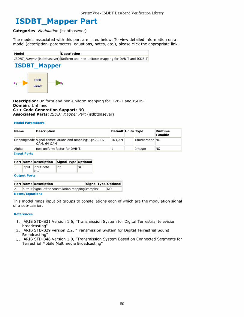
SystemVue - ISDBT Baseband Verification Library
50
ISDBT_Mapper PartCategories: Modulation (isdbtbasever)
The models associated with this part are listed below. To view detailed information on amodel (description, parameters, equations, notes, etc.), please click the appropriate link.
Model Description
ISDBT_Mapper (isdbtbasever) Uniform and non-uniform mapping for DVB-T and ISDB-T
ISDBT_Mapper
Description: Uniform and non-uniform mapping for DVB-T and ISDB-TDomain: UntimedC++ Code Generation Support: NOAssociated Parts: ISDBT Mapper Part (isdbtbasever)
Model Parameters
Name Description Default Units Type RuntimeTunable
MappingMode signal constellations and mapping: QPSK, 16QAM, 64 QAM
16 QAM Enumeration NO
Alpha non-uniform factor for DVB-T. 1 Integer NO
Input Ports
Port Name Description Signal Type Optional
1 input input databits
int NO
Output Ports
Port Name Description Signal Type Optional
2 output signal after constellation mapping complex NO
Notes/Equations
This model maps input bit groups to constellations each of which are the modulation signalof a sub-carrier.
References
ARIB STD-B31 Version 1.6, "Transmission System for Digital Terrestrial television1.broadcasting" ARIB STD-B29 version 2.2, "Transmission System for Digital Terrestrial Sound2.Broadcasting" ARIB STD-B46 Version 1.0, "Transmission System Based on Connected Segments for3.Terrestrial Mobile Multimedia Broadcasting"
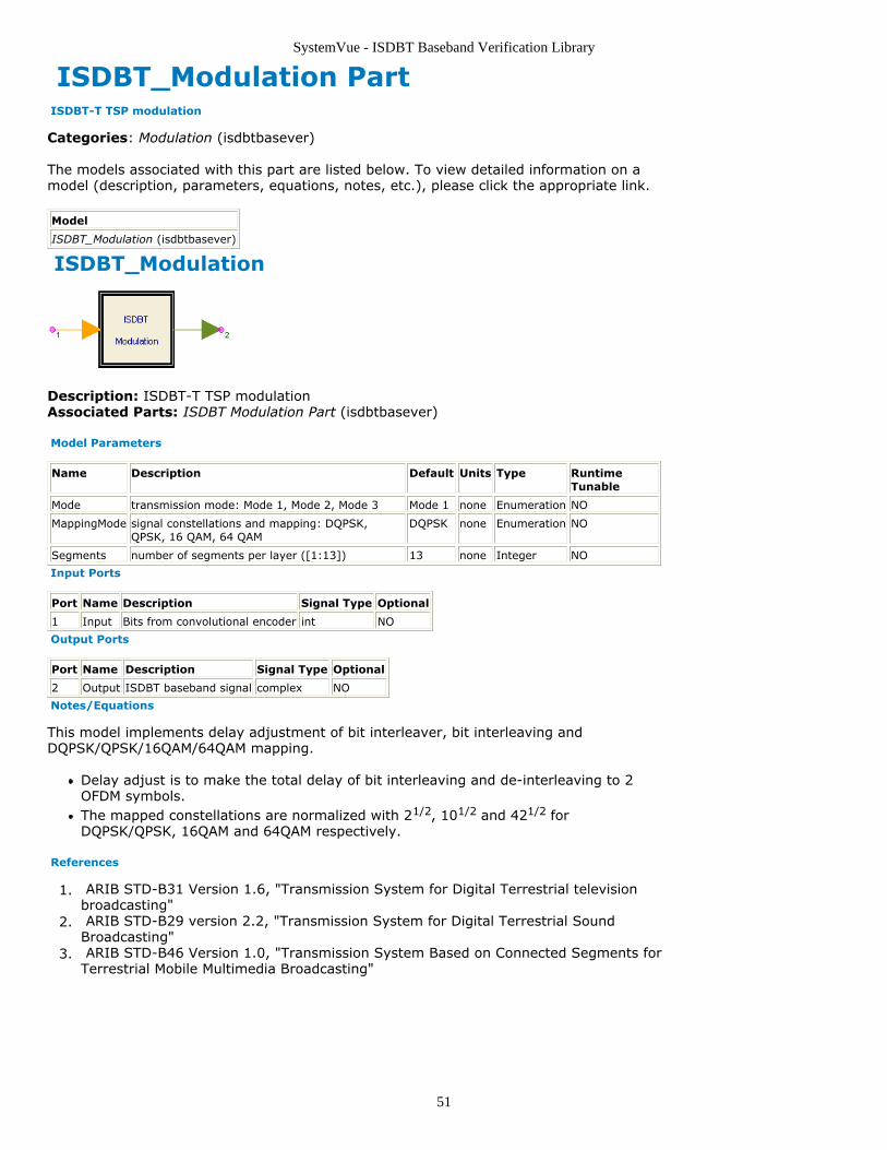
SystemVue - ISDBT Baseband Verification Library
51
ISDBT_Modulation Part ISDBT-T TSP modulation
Categories: Modulation (isdbtbasever)
The models associated with this part are listed below. To view detailed information on amodel (description, parameters, equations, notes, etc.), please click the appropriate link.
Model
ISDBT_Modulation (isdbtbasever)
ISDBT_Modulation
Description: ISDBT-T TSP modulationAssociated Parts: ISDBT Modulation Part (isdbtbasever)
Model Parameters
Name Description Default Units Type RuntimeTunable
Mode transmission mode: Mode 1, Mode 2, Mode 3 Mode 1 none Enumeration NO
MappingMode signal constellations and mapping: DQPSK,QPSK, 16 QAM, 64 QAM
DQPSK none Enumeration NO
Segments number of segments per layer ([1:13]) 13 none Integer NO
Input Ports
Port Name Description Signal Type Optional
1 Input Bits from convolutional encoder int NO
Output Ports
Port Name Description Signal Type Optional
2 Output ISDBT baseband signal complex NO
Notes/Equations
This model implements delay adjustment of bit interleaver, bit interleaving andDQPSK/QPSK/16QAM/64QAM mapping.
Delay adjust is to make the total delay of bit interleaving and de-interleaving to 2OFDM symbols.The mapped constellations are normalized with 21/2, 101/2 and 421/2 forDQPSK/QPSK, 16QAM and 64QAM respectively.
References
ARIB STD-B31 Version 1.6, "Transmission System for Digital Terrestrial television1.broadcasting" ARIB STD-B29 version 2.2, "Transmission System for Digital Terrestrial Sound2.Broadcasting" ARIB STD-B46 Version 1.0, "Transmission System Based on Connected Segments for3.Terrestrial Mobile Multimedia Broadcasting"
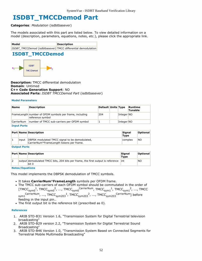
SystemVue - ISDBT Baseband Verification Library
52
ISDBT_TMCCDemod PartCategories: Modulation (isdbtbasever)
The models associated with this part are listed below. To view detailed information on amodel (description, parameters, equations, notes, etc.), please click the appropriate link.
Model Description
ISDBT_TMCCDemod (isdbtbasever) TMCC differential demodulation
ISDBT_TMCCDemod
Description: TMCC differential demodulationDomain: UntimedC++ Code Generation Support: NOAssociated Parts: ISDBT TMCCDemod Part (isdbtbasever)
Model Parameters
Name Description Default Units Type RuntimeTunable
FrameLength number of OFDM symbols per frame, includingreference symbol
204 Integer NO
CarrierNum number of TMCC sub-carriers per OFDM symbol 1 Integer NO
Input Ports
Port Name Description SignalType
Optional
1 input DBPSK modulated TMCC signal to be demodulated,CarrierNum*FrameLength tokens per frame.
complex NO
Output Ports
Port Name Description SignalType
Optional
2 output demodulated TMCC bits, 204 bits per frame, the first output is referencebit 0
int NO
Notes/Equations
This model implements the DBPSK demodulation of TMCC symbols.
It takes CarrierNum*FrameLength symbols per OFDM frame.The TMCC sub-carriers of each OFDM symbol should be commutated in the order of[TMCCsym0
1, TMCCsym02, ..., TMCCsym0
CarrierNum, TMCCsym11, TMCCsym1
2, ..., TMCC
sym1CarrierNum, ..., TMCCsym203
1, TMCCsym2032, ..., TMCCsym203
CarrierNum] before
feeding in the input pin..The first output bit is the reference bit (prescribed as 0).
References
ARIB STD-B31 Version 1.6, "Transmission System for Digital Terrestrial television1.broadcasting" ARIB STD-B29 version 2.2, "Transmission System for Digital Terrestrial Sound2.Broadcasting" ARIB STD-B46 Version 1.0, "Transmission System Based on Connected Segments for3.Terrestrial Mobile Multimedia Broadcasting"
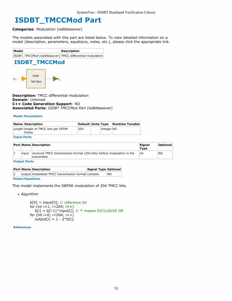
SystemVue - ISDBT Baseband Verification Library
53
ISDBT_TMCCMod PartCategories: Modulation (isdbtbasever)
The models associated with this part are listed below. To view detailed information on amodel (description, parameters, equations, notes, etc.), please click the appropriate link.
Model Description
ISDBT_TMCCMod (isdbtbasever) TMCC differential modulation
ISDBT_TMCCMod
Description: TMCC differential modulationDomain: UntimedC++ Code Generation Support: NOAssociated Parts: ISDBT TMCCMod Part (isdbtbasever)
Model Parameters
Name Description Default Units Type Runtime Tunable
Length length of TMCC bits per OFDMframe
204 Integer NO
Input Ports
Port Name Description SignalType
Optional
1 input received TMCC transmission format (204 bits) before modulation in thetransmitter
int NO
Output Ports
Port Name Description Signal Type Optional
2 output modulated TMCC transmission format complex NO
Notes/Equations
This model implements the DBPSK modulation of 204 TMCC bits.
Algorithm
b[0] = input[0]; // reference bitfor (int i=1; i<204; i++) b[i] = b[i-1]^input[i]; // ^ means EXCLUSIVE ORfor (int i=0; i<204; i++) output[i] = 1 - 2*b[i];
References
SystemVue - ISDBT Baseband Verification Library
54
ISDBT Multiplexing Category Contents
ISDBT DelayCx Part (isdbtbasever)ISDBT DelayInt Part (isdbtbasever)ISDBT DemuxCohSegs Part (isdbtbasever)ISDBT DemuxDiffSegs Part (isdbtbasever)ISDBT DemuxSegs Part (isdbtbasever)ISDBT MuxCohSegs Part (isdbtbasever)ISDBT MuxDiffSegs Part (isdbtbasever)ISDBT SegmentMux Part (isdbtbasever)
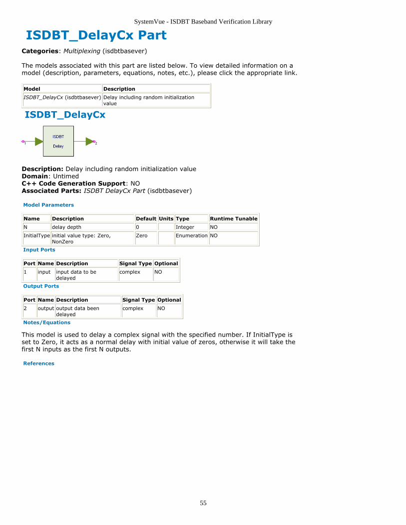
SystemVue - ISDBT Baseband Verification Library
55
ISDBT_DelayCx PartCategories: Multiplexing (isdbtbasever)
The models associated with this part are listed below. To view detailed information on amodel (description, parameters, equations, notes, etc.), please click the appropriate link.
Model Description
ISDBT_DelayCx (isdbtbasever) Delay including random initializationvalue
ISDBT_DelayCx
Description: Delay including random initialization valueDomain: UntimedC++ Code Generation Support: NOAssociated Parts: ISDBT DelayCx Part (isdbtbasever)
Model Parameters
Name Description Default Units Type Runtime Tunable
N delay depth 0 Integer NO
InitialType initial value type: Zero,NonZero
Zero Enumeration NO
Input Ports
Port Name Description Signal Type Optional
1 input input data to bedelayed
complex NO
Output Ports
Port Name Description Signal Type Optional
2 output output data beendelayed
complex NO
Notes/Equations
This model is used to delay a complex signal with the specified number. If InitialType isset to Zero, it acts as a normal delay with initial value of zeros, otherwise it will take thefirst N inputs as the first N outputs.
References
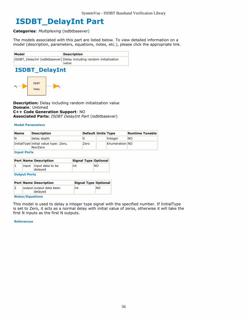
SystemVue - ISDBT Baseband Verification Library
56
ISDBT_DelayInt PartCategories: Multiplexing (isdbtbasever)
The models associated with this part are listed below. To view detailed information on amodel (description, parameters, equations, notes, etc.), please click the appropriate link.
Model Description
ISDBT_DelayInt (isdbtbasever) Delay including random initializationvalue
ISDBT_DelayInt
Description: Delay including random initialization valueDomain: UntimedC++ Code Generation Support: NOAssociated Parts: ISDBT DelayInt Part (isdbtbasever)
Model Parameters
Name Description Default Units Type Runtime Tunable
N delay depth 0 Integer NO
InitialType initial value type: Zero,NonZero
Zero Enumeration NO
Input Ports
Port Name Description Signal Type Optional
1 input input data to bedelayed
int NO
Output Ports
Port Name Description Signal Type Optional
2 output output data beendelayed
int NO
Notes/Equations
This model is used to delay a integer type signal with the specified number. If InitialTypeis set to Zero, it acts as a normal delay with initial value of zeros, otherwise it will take thefirst N inputs as the first N outputs.
References
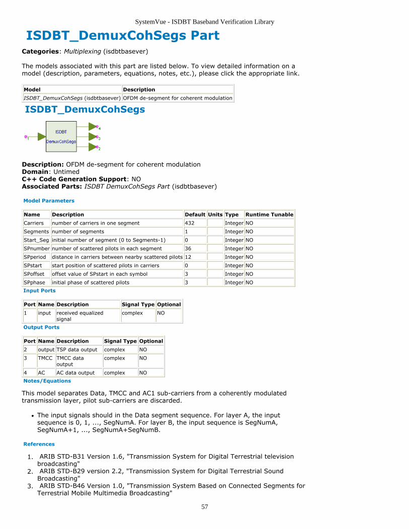
SystemVue - ISDBT Baseband Verification Library
57
ISDBT_DemuxCohSegs PartCategories: Multiplexing (isdbtbasever)
The models associated with this part are listed below. To view detailed information on amodel (description, parameters, equations, notes, etc.), please click the appropriate link.
Model Description
ISDBT_DemuxCohSegs (isdbtbasever) OFDM de-segment for coherent modulation
ISDBT_DemuxCohSegs
Description: OFDM de-segment for coherent modulationDomain: UntimedC++ Code Generation Support: NOAssociated Parts: ISDBT DemuxCohSegs Part (isdbtbasever)
Model Parameters
Name Description Default Units Type Runtime Tunable
Carriers number of carriers in one segment 432 Integer NO
Segments number of segments 1 Integer NO
Start_Seg initial number of segment (0 to Segments-1) 0 Integer NO
SPnumber number of scattered pilots in each segment 36 Integer NO
SPperiod distance in carriers between nearby scattered pilots 12 Integer NO
SPstart start position of scattered pilots in carriers 0 Integer NO
SPoffset offset value of SPstart in each symbol 3 Integer NO
SPphase initial phase of scattered pilots 3 Integer NO
Input Ports
Port Name Description Signal Type Optional
1 input received equalizedsignal
complex NO
Output Ports
Port Name Description Signal Type Optional
2 output TSP data output complex NO
3 TMCC TMCC dataoutput
complex NO
4 AC AC data output complex NO
Notes/Equations
This model separates Data, TMCC and AC1 sub-carriers from a coherently modulatedtransmission layer, pilot sub-carriers are discarded.
The input signals should in the Data segment sequence. For layer A, the inputsequence is 0, 1, ..., SegNumA. For layer B, the input sequence is SegNumA,SegNumA+1, ..., SegNumA+SegNumB.
References
ARIB STD-B31 Version 1.6, "Transmission System for Digital Terrestrial television1.broadcasting" ARIB STD-B29 version 2.2, "Transmission System for Digital Terrestrial Sound2.Broadcasting" ARIB STD-B46 Version 1.0, "Transmission System Based on Connected Segments for3.Terrestrial Mobile Multimedia Broadcasting"
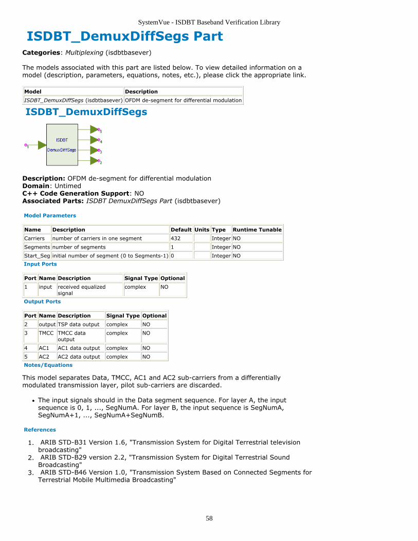
SystemVue - ISDBT Baseband Verification Library
58
ISDBT_DemuxDiffSegs PartCategories: Multiplexing (isdbtbasever)
The models associated with this part are listed below. To view detailed information on amodel (description, parameters, equations, notes, etc.), please click the appropriate link.
Model Description
ISDBT_DemuxDiffSegs (isdbtbasever) OFDM de-segment for differential modulation
ISDBT_DemuxDiffSegs
Description: OFDM de-segment for differential modulationDomain: UntimedC++ Code Generation Support: NOAssociated Parts: ISDBT DemuxDiffSegs Part (isdbtbasever)
Model Parameters
Name Description Default Units Type Runtime Tunable
Carriers number of carriers in one segment 432 Integer NO
Segments number of segments 1 Integer NO
Start_Seg initial number of segment (0 to Segments-1) 0 Integer NO
Input Ports
Port Name Description Signal Type Optional
1 input received equalizedsignal
complex NO
Output Ports
Port Name Description Signal Type Optional
2 output TSP data output complex NO
3 TMCC TMCC dataoutput
complex NO
4 AC1 AC1 data output complex NO
5 AC2 AC2 data output complex NO
Notes/Equations
This model separates Data, TMCC, AC1 and AC2 sub-carriers from a differentiallymodulated transmission layer, pilot sub-carriers are discarded.
The input signals should in the Data segment sequence. For layer A, the inputsequence is 0, 1, ..., SegNumA. For layer B, the input sequence is SegNumA,SegNumA+1, ..., SegNumA+SegNumB.
References
ARIB STD-B31 Version 1.6, "Transmission System for Digital Terrestrial television1.broadcasting" ARIB STD-B29 version 2.2, "Transmission System for Digital Terrestrial Sound2.Broadcasting" ARIB STD-B46 Version 1.0, "Transmission System Based on Connected Segments for3.Terrestrial Mobile Multimedia Broadcasting"
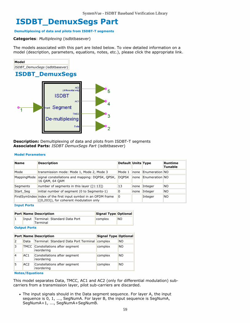
SystemVue - ISDBT Baseband Verification Library
59
ISDBT_DemuxSegs Part Demultiplexing of data and pilots from ISDBT-T segments
Categories: Multiplexing (isdbtbasever)
The models associated with this part are listed below. To view detailed information on amodel (description, parameters, equations, notes, etc.), please click the appropriate link.
Model
ISDBT_DemuxSegs (isdbtbasever)
ISDBT_DemuxSegs
Description: Demultiplexing of data and pilots from ISDBT-T segmentsAssociated Parts: ISDBT DemuxSegs Part (isdbtbasever)
Model Parameters
Name Description Default Units Type RuntimeTunable
Mode transmission mode: Mode 1, Mode 2, Mode 3 Mode 1 none Enumeration NO
MappingMode signal constellations and mapping: DQPSK, QPSK,16 QAM, 64 QAM
DQPSK none Enumeration NO
Segments number of segments in this layer ([1:13]) 13 none Integer NO
Start_Seg initial number of segment (0 to Segments-1) 0 none Integer NO
FirstSymIndex index of the first input symbol in an OFDM frame([0,203]), for coherent modulation only
0 Integer NO
Input Ports
Port Name Description Signal Type Optional
1 Input Terminal: Standard Data PortTerminal
complex NO
Output Ports
Port Name Description Signal Type Optional
2 Data Terminal: Standard Data Port Terminal complex NO
3 TMCC Constellations after segmentreordering
complex NO
4 AC1 Constellations after segmentreordering
complex NO
5 AC2 Constellations after segmentreordering
complex NO
Notes/Equations
This model separates Data, TMCC, AC1 and AC2 (only for differential modulation) sub-carriers from a transmission layer, pilot sub-carriers are discarded.
The input signals should in the Data segment sequence. For layer A, the inputsequence is 0, 1, ..., SegNumA. For layer B, the input sequence is SegNumA,SegNumA+1, ..., SegNumA+SegNumB.
SystemVue - ISDBT Baseband Verification Library
60
References
ARIB STD-B31 Version 1.6, "Transmission System for Digital Terrestrial television1.broadcasting" ARIB STD-B29 version 2.2, "Transmission System for Digital Terrestrial Sound2.Broadcasting" ARIB STD-B46 Version 1.0, "Transmission System Based on Connected Segments for3.Terrestrial Mobile Multimedia Broadcasting"
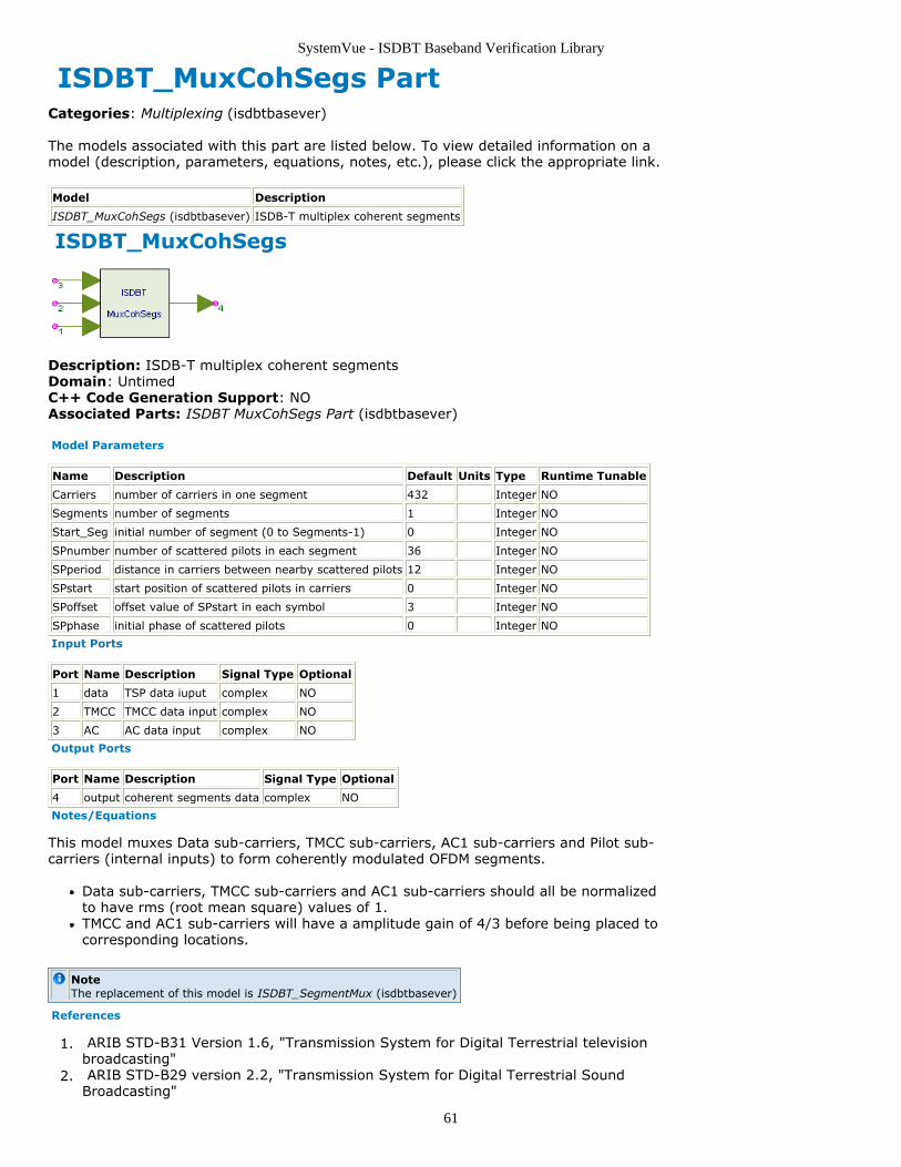
SystemVue - ISDBT Baseband Verification Library
61
ISDBT_MuxCohSegs PartCategories: Multiplexing (isdbtbasever)
The models associated with this part are listed below. To view detailed information on amodel (description, parameters, equations, notes, etc.), please click the appropriate link.
Model Description
ISDBT_MuxCohSegs (isdbtbasever) ISDB-T multiplex coherent segments
ISDBT_MuxCohSegs
Description: ISDB-T multiplex coherent segmentsDomain: UntimedC++ Code Generation Support: NOAssociated Parts: ISDBT MuxCohSegs Part (isdbtbasever)
Model Parameters
Name Description Default Units Type Runtime Tunable
Carriers number of carriers in one segment 432 Integer NO
Segments number of segments 1 Integer NO
Start_Seg initial number of segment (0 to Segments-1) 0 Integer NO
SPnumber number of scattered pilots in each segment 36 Integer NO
SPperiod distance in carriers between nearby scattered pilots 12 Integer NO
SPstart start position of scattered pilots in carriers 0 Integer NO
SPoffset offset value of SPstart in each symbol 3 Integer NO
SPphase initial phase of scattered pilots 0 Integer NO
Input Ports
Port Name Description Signal Type Optional
1 data TSP data iuput complex NO
2 TMCC TMCC data input complex NO
3 AC AC data input complex NO
Output Ports
Port Name Description Signal Type Optional
4 output coherent segments data complex NO
Notes/Equations
This model muxes Data sub-carriers, TMCC sub-carriers, AC1 sub-carriers and Pilot sub-carriers (internal inputs) to form coherently modulated OFDM segments.
Data sub-carriers, TMCC sub-carriers and AC1 sub-carriers should all be normalizedto have rms (root mean square) values of 1.TMCC and AC1 sub-carriers will have a amplitude gain of 4/3 before being placed tocorresponding locations.
NoteThe replacement of this model is ISDBT_SegmentMux (isdbtbasever)
References
ARIB STD-B31 Version 1.6, "Transmission System for Digital Terrestrial television1.broadcasting" ARIB STD-B29 version 2.2, "Transmission System for Digital Terrestrial Sound2.Broadcasting"
SystemVue - ISDBT Baseband Verification Library
62
ARIB STD-B46 Version 1.0, "Transmission System Based on Connected Segments for3.Terrestrial Mobile Multimedia Broadcasting"
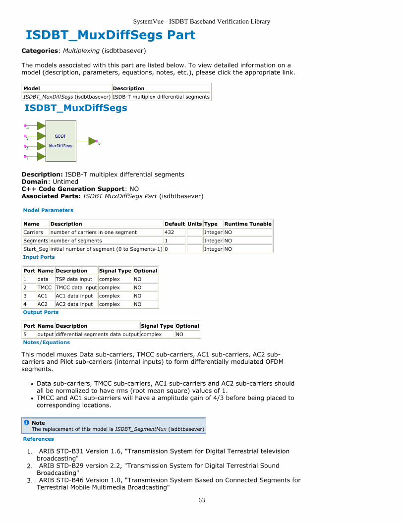
SystemVue - ISDBT Baseband Verification Library
63
ISDBT_MuxDiffSegs PartCategories: Multiplexing (isdbtbasever)
The models associated with this part are listed below. To view detailed information on amodel (description, parameters, equations, notes, etc.), please click the appropriate link.
Model Description
ISDBT_MuxDiffSegs (isdbtbasever) ISDB-T multiplex differential segments
ISDBT_MuxDiffSegs
Description: ISDB-T multiplex differential segmentsDomain: UntimedC++ Code Generation Support: NOAssociated Parts: ISDBT MuxDiffSegs Part (isdbtbasever)
Model Parameters
Name Description Default Units Type Runtime Tunable
Carriers number of carriers in one segment 432 Integer NO
Segments number of segments 1 Integer NO
Start_Seg initial number of segment (0 to Segments-1) 0 Integer NO
Input Ports
Port Name Description Signal Type Optional
1 data TSP data input complex NO
2 TMCC TMCC data input complex NO
3 AC1 AC1 data input complex NO
4 AC2 AC2 data input complex NO
Output Ports
Port Name Description Signal Type Optional
5 output differential segments data output complex NO
Notes/Equations
This model muxes Data sub-carriers, TMCC sub-carriers, AC1 sub-carriers, AC2 sub-carriers and Pilot sub-carriers (internal inputs) to form differentially modulated OFDMsegments.
Data sub-carriers, TMCC sub-carriers, AC1 sub-carriers and AC2 sub-carriers shouldall be normalized to have rms (root mean square) values of 1.TMCC and AC1 sub-carriers will have a amplitude gain of 4/3 before being placed tocorresponding locations.
NoteThe replacement of this model is ISDBT_SegmentMux (isdbtbasever)
References
ARIB STD-B31 Version 1.6, "Transmission System for Digital Terrestrial television1.broadcasting" ARIB STD-B29 version 2.2, "Transmission System for Digital Terrestrial Sound2.Broadcasting" ARIB STD-B46 Version 1.0, "Transmission System Based on Connected Segments for3.Terrestrial Mobile Multimedia Broadcasting"
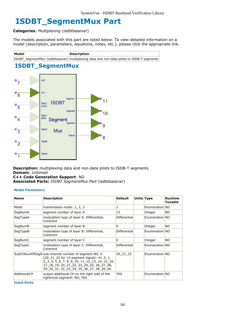
SystemVue - ISDBT Baseband Verification Library
64
ISDBT_SegmentMux PartCategories: Multiplexing (isdbtbasever)
The models associated with this part are listed below. To view detailed information on amodel (description, parameters, equations, notes, etc.), please click the appropriate link.
Model Description
ISDBT_SegmentMux (isdbtbasever) multiplexing data and non-data pilots to ISDB-T segments
ISDBT_SegmentMux
Description: multiplexing data and non-data pilots to ISDB-T segmentsDomain: UntimedC++ Code Generation Support: NOAssociated Parts: ISDBT SegmentMux Part (isdbtbasever)
Model Parameters
Name Description Default Units Type RuntimeTunable
Mode transmission mode: 1, 2, 3 1 Enumeration NO
SegNumA segment number of layer A 13 Integer NO
SegTypeA modulation type of layer A: Differential,Coherent
Differential Enumeration NO
SegNumB segment number of layer B 0 Integer NO
SegTypeB modulation type of layer B: Differential,Coherent
Differential Enumeration NO
SegNumC segment number of layer C 0 Integer NO
SegTypeC modulation type of layer C: Differential,Coherent
Differential Enumeration NO
SubChNumOfSeg0 sub-channel number of segment NO. 0(20_21_22 for 13-segment signal): 41_0_1,2_3_4, 5_6_7, 8_9_10, 11_12_13, 14_15_16,17_18_19, 20_21_22, 23_24_25, 26_27_28,29_30_31, 32_33_34, 35_36_37, 38_39_40
20_21_22 Enumeration NO
AdditionalCP output additional CP on the right side of therightmost segment: NO, YES
YES Enumeration NO
Input Ports
SystemVue - ISDBT Baseband Verification Library
65
Port Name Description Signal Type Optional
1 DataA Layer A TSP subcarrier data input complex NO
2 DataB Layer B TSP subcarrier data input complex YES
3 DataC Layer C TSP subcarrier data input complex YES
4 TMCC_Diff Differential TMCC subcarrier data input, 1 per OFDMsymbol
complex YES
5 TMCC_Coh Coherent TMCC subcarrier data input, 1 per OFDM symbol complex YES
6 AC1 AC1 subcarrier data input complex NO
7 AC2 AC2 subcarrier data input complex YES
Output Ports
Port Name Description SignalType
Optional
8 Output segments subcarrier output in the order of '...3 1 0 2 4 ... CP' complex NO
9 SegOutA segments subcarrier output of layer A in the order of '0 12...SegNumA-1'
complex NO
10 SegOutB segments subcarrier output of layer B in the order of '0 12...SegNumB-1'
complex NO
11 SegOutC segments subcarrier output of layer C in the order of '0 12...SegNumC-1'
complex NO
Notes/Equations
This model multiplexes Data, TMCC, AC1 and AC2 sub-carriers to form OFDM segmentsaccording to ISDB-T OFDM Frame Structuring (isdbtbasever).
FeaturesSupport 1, 2 and 3 layer multiplexing.Sub-channel number of setment No. 0 can be specified.The rightmost CP can be removed to adapt ISDB-Tsb and ISDB-Tmm connectedtransmission.
Parameter detailsSegmentsA+SegmentsB+SegmentsC must be no more than 13. SegmentsAshould not be 0. SegmentsB should not be 0 if SegmentsC is non-zero.SubChNumOfSeg0 specifies the sub-channel number of OFDM segment No. 0,only for 1-segment and 3-segment transmission. For 13-segment signal, itshould always be 20_21_22. Please refer to ISDB-T OFDM Frame Structuring(isdbtbasever) for more details.AdditionalCP can remove the rightmost CP for connected transmission.
I/O detailsDataA must always be connceted. DataB and DataC must be connected whenparameter SegNumB and SegNumC are non-zero.TMCC_Coh must be connected when there're coherently modulated segments.TMCC_Diff must be connected when there're differentially modulatedsegments.AC1 must always be connected. AC2 must be connected when there'redifferentially modulated segments.TMCC_Coh, TMCC_Diff, AC1 and AC2 should have rms values of 1. A gain of4/3 will be applied aotumatically.Output is in the segment order of [-11,-9,...,1,0,2,...,10,12].SegOutA, SegOutB and SegOutC are in the segment order of [0,1,...].
References
ARIB STD-B31 Version 1.6, "Transmission System for Digital Terrestrial television1.broadcasting" ARIB STD-B29 version 2.2, "Transmission System for Digital Terrestrial Sound2.Broadcasting" ARIB STD-B46 Version 1.0, "Transmission System Based on Connected Segments for3.Terrestrial Mobile Multimedia Broadcasting"
SystemVue - ISDBT Baseband Verification Library
66
ISDBT OFDM Category Contents
ISDBT 2DChEstimator Part (isdbtbasever)ISDBT LoadIFFTBuff Part (isdbtbasever)ISDBT MLCorrelator Part (isdbtbasever)ISDBT MLPeakSearch Part (isdbtbasever)ISDBT OneLayOFDMDemod Part (isdbtbasever)ISDBT SymbolAlign Part (isdbtbasever)ISDBT ThreeLayOFDMDemod Part (isdbtbasever)ISDBT TwoLayOFDMDemod Part (isdbtbasever)
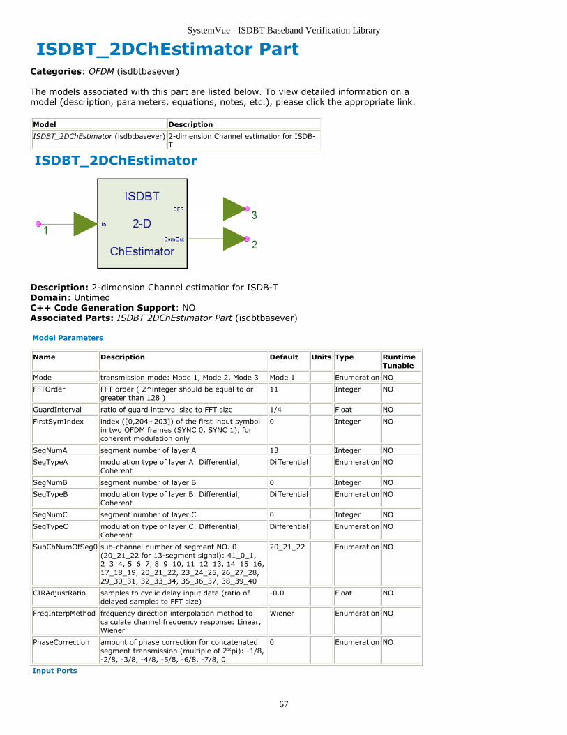
SystemVue - ISDBT Baseband Verification Library
67
ISDBT_2DChEstimator PartCategories: OFDM (isdbtbasever)
The models associated with this part are listed below. To view detailed information on amodel (description, parameters, equations, notes, etc.), please click the appropriate link.
Model Description
ISDBT_2DChEstimator (isdbtbasever) 2-dimension Channel estimatior for ISDB-T
ISDBT_2DChEstimator
Description: 2-dimension Channel estimatior for ISDB-TDomain: UntimedC++ Code Generation Support: NOAssociated Parts: ISDBT 2DChEstimator Part (isdbtbasever)
Model Parameters
Name Description Default Units Type RuntimeTunable
Mode transmission mode: Mode 1, Mode 2, Mode 3 Mode 1 Enumeration NO
FFTOrder FFT order ( 2^integer should be equal to orgreater than 128 )
11 Integer NO
GuardInterval ratio of guard interval size to FFT size 1/4 Float NO
FirstSymIndex index ([0,204+203]) of the first input symbolin two OFDM frames (SYNC 0, SYNC 1), forcoherent modulation only
0 Integer NO
SegNumA segment number of layer A 13 Integer NO
SegTypeA modulation type of layer A: Differential,Coherent
Differential Enumeration NO
SegNumB segment number of layer B 0 Integer NO
SegTypeB modulation type of layer B: Differential,Coherent
Differential Enumeration NO
SegNumC segment number of layer C 0 Integer NO
SegTypeC modulation type of layer C: Differential,Coherent
Differential Enumeration NO
SubChNumOfSeg0 sub-channel number of segment NO. 0(20_21_22 for 13-segment signal): 41_0_1,2_3_4, 5_6_7, 8_9_10, 11_12_13, 14_15_16,17_18_19, 20_21_22, 23_24_25, 26_27_28,29_30_31, 32_33_34, 35_36_37, 38_39_40
20_21_22 Enumeration NO
CIRAdjustRatio samples to cyclic delay input data (ratio ofdelayed samples to FFT size)
-0.0 Float NO
FreqInterpMethod frequency direction interpolation method tocalculate channel frequency response: Linear,Wiener
Wiener Enumeration NO
PhaseCorrection amount of phase correction for concatenatedsegment transmission (multiple of 2*pi): -1/8,-2/8, -3/8, -4/8, -5/8, -6/8, -7/8, 0
0 Enumeration NO
Input Ports
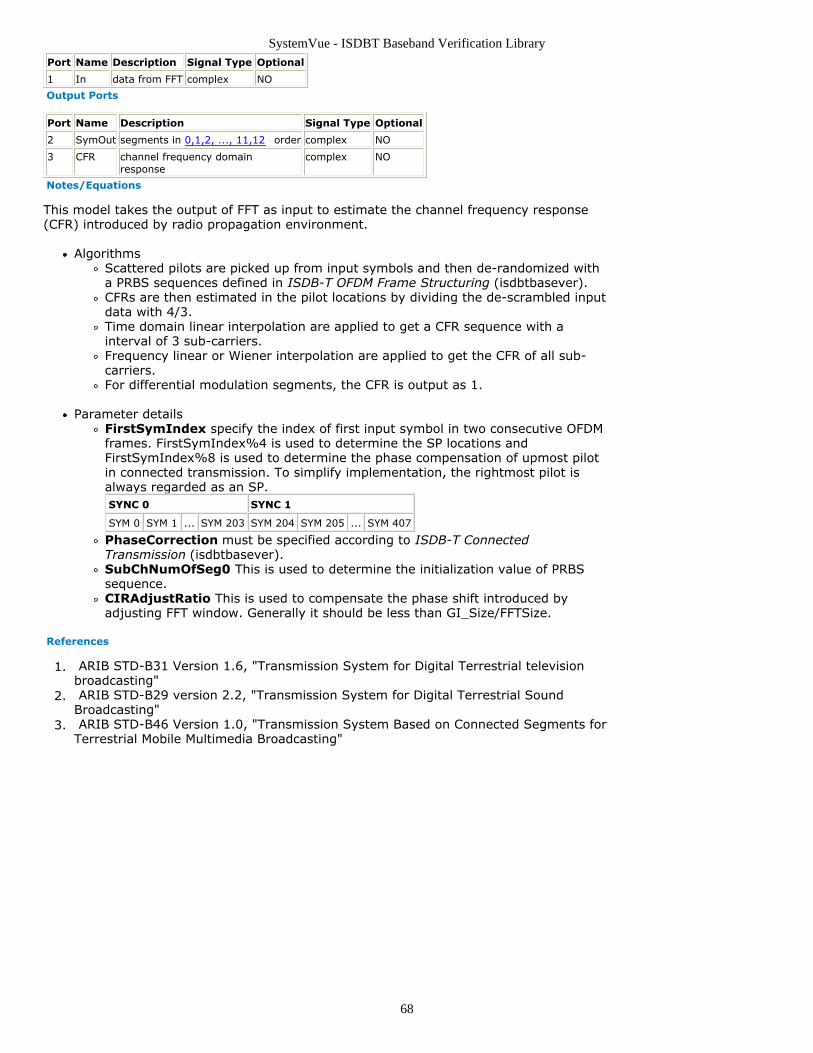
SystemVue - ISDBT Baseband Verification Library
68
Port Name Description Signal Type Optional
1 In data from FFT complex NO
Output Ports
Port Name Description Signal Type Optional
2 SymOut segments in 0,1,2, ..., 11,12 order complex NO
3 CFR channel frequency domainresponse
complex NO
Notes/Equations
This model takes the output of FFT as input to estimate the channel frequency response(CFR) introduced by radio propagation environment.
AlgorithmsScattered pilots are picked up from input symbols and then de-randomized witha PRBS sequences defined in ISDB-T OFDM Frame Structuring (isdbtbasever).CFRs are then estimated in the pilot locations by dividing the de-scrambled inputdata with 4/3.Time domain linear interpolation are applied to get a CFR sequence with ainterval of 3 sub-carriers.Frequency linear or Wiener interpolation are applied to get the CFR of all sub-carriers.For differential modulation segments, the CFR is output as 1.
Parameter detailsFirstSymIndex specify the index of first input symbol in two consecutive OFDMframes. FirstSymIndex%4 is used to determine the SP locations andFirstSymIndex%8 is used to determine the phase compensation of upmost pilotin connected transmission. To simplify implementation, the rightmost pilot isalways regarded as an SP.SYNC 0 SYNC 1
SYM 0 SYM 1 ... SYM 203 SYM 204 SYM 205 ... SYM 407
PhaseCorrection must be specified according to ISDB-T ConnectedTransmission (isdbtbasever).SubChNumOfSeg0 This is used to determine the initialization value of PRBSsequence.CIRAdjustRatio This is used to compensate the phase shift introduced byadjusting FFT window. Generally it should be less than GI_Size/FFTSize.
References
ARIB STD-B31 Version 1.6, "Transmission System for Digital Terrestrial television1.broadcasting" ARIB STD-B29 version 2.2, "Transmission System for Digital Terrestrial Sound2.Broadcasting" ARIB STD-B46 Version 1.0, "Transmission System Based on Connected Segments for3.Terrestrial Mobile Multimedia Broadcasting"
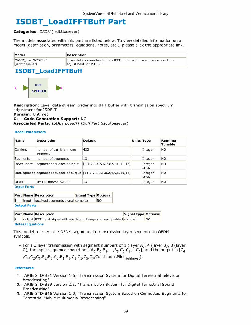
SystemVue - ISDBT Baseband Verification Library
69
ISDBT_LoadIFFTBuff PartCategories: OFDM (isdbtbasever)
The models associated with this part are listed below. To view detailed information on amodel (description, parameters, equations, notes, etc.), please click the appropriate link.
Model Description
ISDBT_LoadIFFTBuff(isdbtbasever)
Layer data stream loader into IFFT buffer with transmission spectrumadjustment for ISDB-T
ISDBT_LoadIFFTBuff
Description: Layer data stream loader into IFFT buffer with transmission spectrumadjustment for ISDB-TDomain: UntimedC++ Code Generation Support: NOAssociated Parts: ISDBT LoadIFFTBuff Part (isdbtbasever)
Model Parameters
Name Description Default Units Type RuntimeTunable
Carriers number of carriers in onesegment
432 Integer NO
Segments number of segments 13 Integer NO
InSequence segment sequence at input [0,1,2,3,4,5,6,7,8,9,10,11,12] Integerarray
NO
OutSequence segment sequence at output [11,9,7,5,3,1,0,2,4,6,8,10,12] Integerarray
NO
Order IFFT points=2^Order 13 Integer NO
Input Ports
Port Name Description Signal Type Optional
1 input received segments signal complex NO
Output Ports
Port Name Description Signal Type Optional
2 output IFFT input signal with spectrum change and zero padded complex NO
Notes/Equations
This model reorders the OFDM segments in transmission layer sequence to OFDMsymbols.
For a 3 layer transmission with segment numbers of 1 (layer A), 4 (layer B), 8 (layerC), the input sequence should be: [A0,B0,B1,...,B3,C0,C1,...C7], and the output is [C6
,C4,C2,C0,B2,B0,A0,B1,B3,C1,C3,C5,C7,ContinuousPilotrightmost].
References
ARIB STD-B31 Version 1.6, "Transmission System for Digital Terrestrial television1.broadcasting" ARIB STD-B29 version 2.2, "Transmission System for Digital Terrestrial Sound2.Broadcasting" ARIB STD-B46 Version 1.0, "Transmission System Based on Connected Segments for3.Terrestrial Mobile Multimedia Broadcasting"
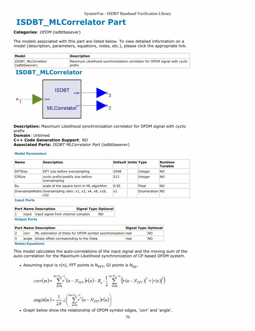
SystemVue - ISDBT Baseband Verification Library
70
ISDBT_MLCorrelator PartCategories: OFDM (isdbtbasever)
The models associated with this part are listed below. To view detailed information on amodel (description, parameters, equations, notes, etc.), please click the appropriate link.
Model Description
ISDBT_MLCorrelator(isdbtbasever)
Maximum Likelihood synchronization correlator for OFDM signal with cyclicprefix
ISDBT_MLCorrelator
Description: Maximum Likelihood synchronization correlator for OFDM signal with cyclicprefixDomain: UntimedC++ Code Generation Support: NOAssociated Parts: ISDBT MLCorrelator Part (isdbtbasever)
Model Parameters
Name Description Default Units Type RuntimeTunable
DFTSize DFT size before oversampling 2048 Integer NO
CPSize cyclic prefix/postfix size beforeoversampling
512 Integer NO
Ru scale of the square term in ML algorithm 0.95 Float NO
OversampleRatio Oversampling ratio: x1, x2, x4, x8, x16,x32
x1 Enumeration NO
Input Ports
Port Name Description Signal Type Optional
1 input input signal from channel complex NO
Output Ports
Port Name Description Signal Type Optional
2 corr ML estimation of theta for OFDM symbol synchronization real NO
3 angle phase offset corresponding to the theta real NO
Notes/Equations
This model calculates the auto-correlations of the input signal and the moving sum of theauto-correlation for the Maximum-Likelihood synchronization of CP based OFDM system.
Assuming input is r(n), FFT points is NFFT, GI points is NGI,
Graph below show the relationship of OFDM symbol edges, 'corr' and 'angle'.
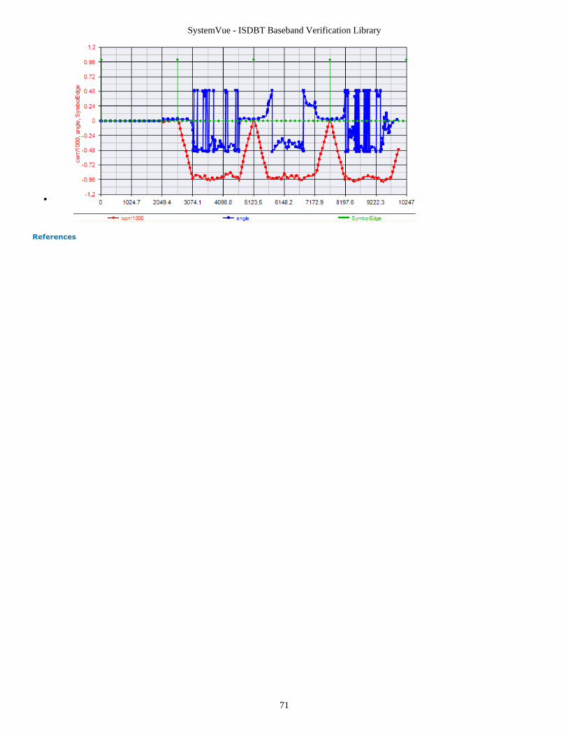
SystemVue - ISDBT Baseband Verification Library
71
References
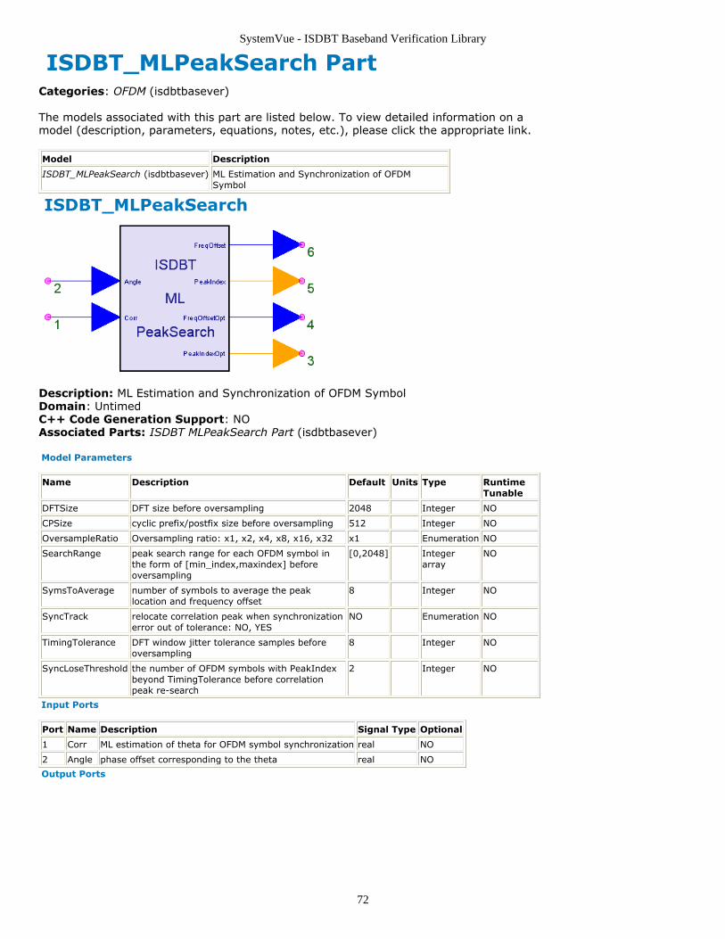
SystemVue - ISDBT Baseband Verification Library
72
ISDBT_MLPeakSearch PartCategories: OFDM (isdbtbasever)
The models associated with this part are listed below. To view detailed information on amodel (description, parameters, equations, notes, etc.), please click the appropriate link.
Model Description
ISDBT_MLPeakSearch (isdbtbasever) ML Estimation and Synchronization of OFDMSymbol
ISDBT_MLPeakSearch
Description: ML Estimation and Synchronization of OFDM SymbolDomain: UntimedC++ Code Generation Support: NOAssociated Parts: ISDBT MLPeakSearch Part (isdbtbasever)
Model Parameters
Name Description Default Units Type RuntimeTunable
DFTSize DFT size before oversampling 2048 Integer NO
CPSize cyclic prefix/postfix size before oversampling 512 Integer NO
OversampleRatio Oversampling ratio: x1, x2, x4, x8, x16, x32 x1 Enumeration NO
SearchRange peak search range for each OFDM symbol inthe form of [min_index,maxindex] beforeoversampling
[0,2048] Integerarray
NO
SymsToAverage number of symbols to average the peaklocation and frequency offset
8 Integer NO
SyncTrack relocate correlation peak when synchronizationerror out of tolerance: NO, YES
NO Enumeration NO
TimingTolerance DFT window jitter tolerance samples beforeoversampling
8 Integer NO
SyncLoseThreshold the number of OFDM symbols with PeakIndexbeyond TimingTolerance before correlationpeak re-search
2 Integer NO
Input Ports
Port Name Description Signal Type Optional
1 Corr ML estimation of theta for OFDM symbol synchronization real NO
2 Angle phase offset corresponding to the theta real NO
Output Ports
SystemVue - ISDBT Baseband Verification Library
73
Port Name Description SignalType
Optional
3 PeakIndexOpt optimal correlation peak index in a full OFDM symbol[0,Oversampled DFTSize+CPSize)
int NO
4 FreqOffsetOpt optimal normalized frequency error (multiple of sub-carrierspacing)
real NO
5 PeakIndex correlation peak index in a full OFDM symbol [0,OversampledDFTSize+CPSize)
int NO
6 FreqOffset normalized frequency error (multiple of sub-carrier spacing) real NO
Notes/Equations
This model searches the peaks from the output of the ISDBT_MLCorrelator for theMaximum-Likelihood synchronization of CP based OFDM system.
The peak should be lies in the range of SearchRange.An optimized peak index (OFDM symbol edge index in an input block of NFFT+NGI
samples) is obtained by averaging the SymsToAverage peak indices.An optimized frequency offset is obtained by averaging the angles at theSymsToAverage peak indices. The frequency offset is normalized by sub-carrierspacing, i.e.
ξ = (FcTx-FcRx)*TFFT
Where Fc is the center frequency of up-convertor/down-convertor oscillator.If SyncTrack is NO, the output peak index and frequency offset shall remains thesame after the first averaging. If SyncTrack is YES, the output peak index andfrequency offset shall be recalculated if the distance between real-time peak index inthe recent input samples and the optimized peak index are larger thanTimingTolerance SyncLoseThreshold times.
References
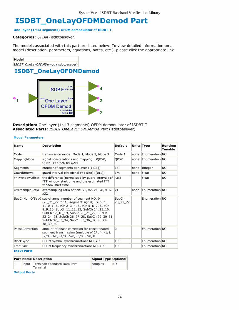
SystemVue - ISDBT Baseband Verification Library
74
ISDBT_OneLayOFDMDemod Part One-layer (1~13 segments) OFDM demodulator of ISDBT-T
Categories: OFDM (isdbtbasever)
The models associated with this part are listed below. To view detailed information on amodel (description, parameters, equations, notes, etc.), please click the appropriate link.
Model
ISDBT_OneLayOFDMDemod (isdbtbasever)
ISDBT_OneLayOFDMDemod
Description: One-layer (1~13 segments) OFDM demodulator of ISDBT-TAssociated Parts: ISDBT OneLayOFDMDemod Part (isdbtbasever)
Model Parameters
Name Description Default Units Type RuntimeTunable
Mode transmission mode: Mode 1, Mode 2, Mode 3 Mode 1 none Enumeration NO
MappingMode signal constellations and mapping: DQPSK,QPSK, 16 QAM, 64 QAM
QPSK none Enumeration NO
Segments number of segments per layer ([1:13]) 13 none Integer NO
GuardInterval guard interval (fractional FFT size) ([0:1]) 1/4 none Float NO
FFTWindowOffset the difference (normalized by guard interval) ofFFT window start time and the estimated FFTwindow start time
-3/8 Float NO
OversampleRatio oversampling ratio option: x1, x2, x4, x8, x16,x32
x1 none Enumeration NO
SubChNumOfSeg0 sub-channel number of segment NO. 0(20_21_22 for 13-segment signal): SubCh41_0_1, SubCh 2_3_4, SubCh 5_6_7, SubCh8_9_10, SubCh 11_12_13, SubCh 14_15_16,SubCh 17_18_19, SubCh 20_21_22, SubCh23_24_25, SubCh 26_27_28, SubCh 29_30_31,SubCh 32_33_34, SubCh 35_36_37, SubCh38_39_40
SubCh20_21_22
Enumeration NO
PhaseCorrection amount of phase correction for concatenatedsegment transmission (multiple of 2*pi): -1/8,-2/8, -3/8, -4/8, -5/8, -6/8, -7/8, 0
0 Enumeration NO
BlockSync OFDM symbol synchronization: NO, YES YES Enumeration NO
FreqSync OFDM frequency synchronization: NO, YES YES Enumeration NO
Input Ports
Port Name Description Signal Type Optional
1 Input Terminal: Standard Data PortTerminal
complex NO
Output Ports
SystemVue - ISDBT Baseband Verification Library
75
Port Name Description Signal Type Optional
2 Constellation Constellations after segment reordering, with pilots complex NO
3 Data Equalized data subcarriers complex NO
4 CFR Channel Frequency Response, Data only complex NO
Notes/Equations
This model implements OFDM synchronization, channel estimation/equalization andsegment de-multiplexing of 1-layer ISDB-T signal.
Parameter detailsFFT windows can be adjusted by FFTWindowOffset within [-NGI,0]/NGI.
SubChNumOfSeg0 specifies the sub-channel number of OFDM segment 0, onlyfor 1-segment and 3-segment transmission. For 13-segment signal, it shouldalways be SubCh_20_21_22.PhaseCorrection provides support for connected transmission according toISDB-T Connected Transmission (isdbtbasever).BlockSync and FreqSync can be used to bypass block synchronization andfrequency synchronization respectively.
I/O detailsConstellation outputs the equalized sub-carriers (including data, pilots, TMCCand ACs) in segment sequence of 0,1,...12. Rightmost CP is not included.Data outputs the equalized data sub-carriers.CFR outputs the channel frequency response, i.e. h(k) on data sub-carriers.
NotesThis model supports the demodulation of 1-segment, 3-segment and 13-segment ISDB-T signal.Frame head of the input ISDB-T signal must be within the first [0,NFFT] samples,
otherwise the output may be incorrect due to pilot pattern synchronizationfailure.
References
ARIB STD-B31 Version 1.6, "Transmission System for Digital Terrestrial television1.broadcasting" ARIB STD-B29 version 2.2, "Transmission System for Digital Terrestrial Sound2.Broadcasting" ARIB STD-B46 Version 1.0, "Transmission System Based on Connected Segments for3.Terrestrial Mobile Multimedia Broadcasting"
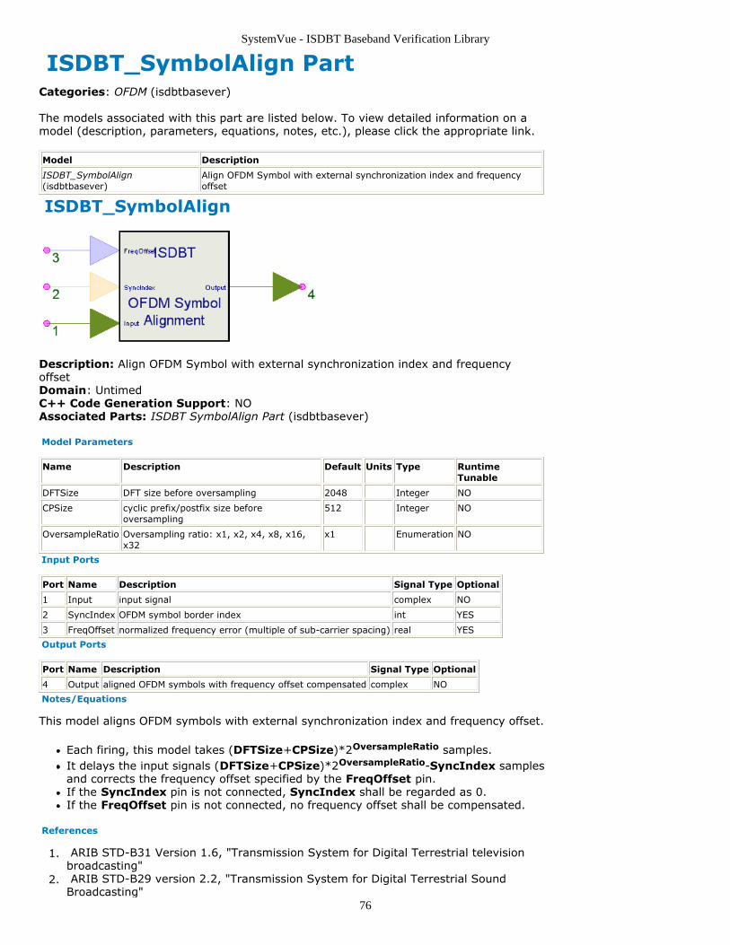
SystemVue - ISDBT Baseband Verification Library
76
ISDBT_SymbolAlign PartCategories: OFDM (isdbtbasever)
The models associated with this part are listed below. To view detailed information on amodel (description, parameters, equations, notes, etc.), please click the appropriate link.
Model Description
ISDBT_SymbolAlign(isdbtbasever)
Align OFDM Symbol with external synchronization index and frequencyoffset
ISDBT_SymbolAlign
Description: Align OFDM Symbol with external synchronization index and frequencyoffsetDomain: UntimedC++ Code Generation Support: NOAssociated Parts: ISDBT SymbolAlign Part (isdbtbasever)
Model Parameters
Name Description Default Units Type RuntimeTunable
DFTSize DFT size before oversampling 2048 Integer NO
CPSize cyclic prefix/postfix size beforeoversampling
512 Integer NO
OversampleRatio Oversampling ratio: x1, x2, x4, x8, x16,x32
x1 Enumeration NO
Input Ports
Port Name Description Signal Type Optional
1 Input input signal complex NO
2 SyncIndex OFDM symbol border index int YES
3 FreqOffset normalized frequency error (multiple of sub-carrier spacing) real YES
Output Ports
Port Name Description Signal Type Optional
4 Output aligned OFDM symbols with frequency offset compensated complex NO
Notes/Equations
This model aligns OFDM symbols with external synchronization index and frequency offset.
Each firing, this model takes (DFTSize+CPSize)*2OversampleRatio samples.It delays the input signals (DFTSize+CPSize)*2OversampleRatio-SyncIndex samplesand corrects the frequency offset specified by the FreqOffset pin.If the SyncIndex pin is not connected, SyncIndex shall be regarded as 0.If the FreqOffset pin is not connected, no frequency offset shall be compensated.
References
ARIB STD-B31 Version 1.6, "Transmission System for Digital Terrestrial television1.broadcasting" ARIB STD-B29 version 2.2, "Transmission System for Digital Terrestrial Sound2.Broadcasting"
SystemVue - ISDBT Baseband Verification Library
77
ARIB STD-B46 Version 1.0, "Transmission System Based on Connected Segments for3.Terrestrial Mobile Multimedia Broadcasting"
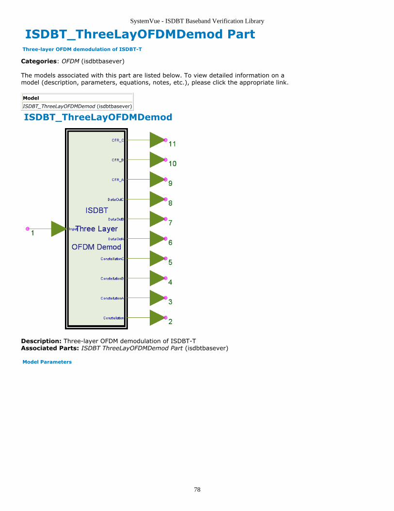
SystemVue - ISDBT Baseband Verification Library
78
ISDBT_ThreeLayOFDMDemod Part Three-layer OFDM demodulation of ISDBT-T
Categories: OFDM (isdbtbasever)
The models associated with this part are listed below. To view detailed information on amodel (description, parameters, equations, notes, etc.), please click the appropriate link.
Model
ISDBT_ThreeLayOFDMDemod (isdbtbasever)
ISDBT_ThreeLayOFDMDemod
Description: Three-layer OFDM demodulation of ISDBT-TAssociated Parts: ISDBT ThreeLayOFDMDemod Part (isdbtbasever)
Model Parameters
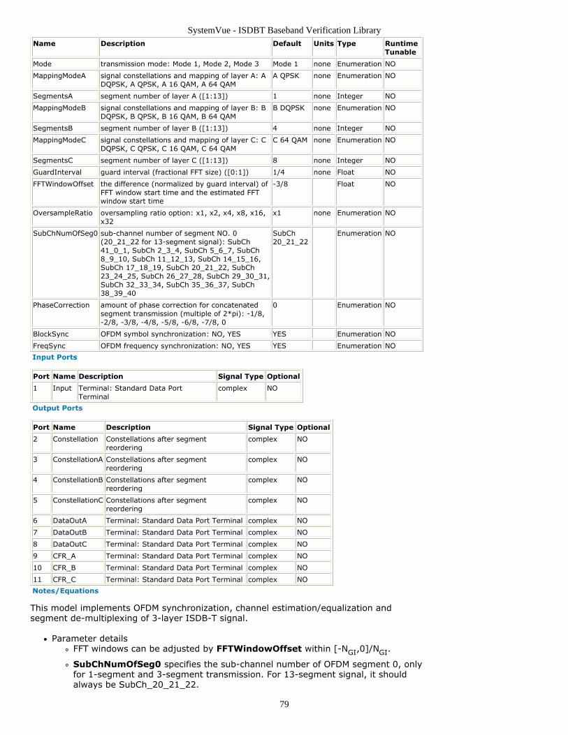
SystemVue - ISDBT Baseband Verification Library
79
Name Description Default Units Type RuntimeTunable
Mode transmission mode: Mode 1, Mode 2, Mode 3 Mode 1 none Enumeration NO
MappingModeA signal constellations and mapping of layer A: ADQPSK, A QPSK, A 16 QAM, A 64 QAM
A QPSK none Enumeration NO
SegmentsA segment number of layer A ([1:13]) 1 none Integer NO
MappingModeB signal constellations and mapping of layer B: BDQPSK, B QPSK, B 16 QAM, B 64 QAM
B DQPSK none Enumeration NO
SegmentsB segment number of layer B ([1:13]) 4 none Integer NO
MappingModeC signal constellations and mapping of layer C: CDQPSK, C QPSK, C 16 QAM, C 64 QAM
C 64 QAM none Enumeration NO
SegmentsC segment number of layer C ([1:13]) 8 none Integer NO
GuardInterval guard interval (fractional FFT size) ([0:1]) 1/4 none Float NO
FFTWindowOffset the difference (normalized by guard interval) ofFFT window start time and the estimated FFTwindow start time
-3/8 Float NO
OversampleRatio oversampling ratio option: x1, x2, x4, x8, x16,x32
x1 none Enumeration NO
SubChNumOfSeg0 sub-channel number of segment NO. 0(20_21_22 for 13-segment signal): SubCh41_0_1, SubCh 2_3_4, SubCh 5_6_7, SubCh8_9_10, SubCh 11_12_13, SubCh 14_15_16,SubCh 17_18_19, SubCh 20_21_22, SubCh23_24_25, SubCh 26_27_28, SubCh 29_30_31,SubCh 32_33_34, SubCh 35_36_37, SubCh38_39_40
SubCh20_21_22
Enumeration NO
PhaseCorrection amount of phase correction for concatenatedsegment transmission (multiple of 2*pi): -1/8,-2/8, -3/8, -4/8, -5/8, -6/8, -7/8, 0
0 Enumeration NO
BlockSync OFDM symbol synchronization: NO, YES YES Enumeration NO
FreqSync OFDM frequency synchronization: NO, YES YES Enumeration NO
Input Ports
Port Name Description Signal Type Optional
1 Input Terminal: Standard Data PortTerminal
complex NO
Output Ports
Port Name Description Signal Type Optional
2 Constellation Constellations after segmentreordering
complex NO
3 ConstellationA Constellations after segmentreordering
complex NO
4 ConstellationB Constellations after segmentreordering
complex NO
5 ConstellationC Constellations after segmentreordering
complex NO
6 DataOutA Terminal: Standard Data Port Terminal complex NO
7 DataOutB Terminal: Standard Data Port Terminal complex NO
8 DataOutC Terminal: Standard Data Port Terminal complex NO
9 CFR_A Terminal: Standard Data Port Terminal complex NO
10 CFR_B Terminal: Standard Data Port Terminal complex NO
11 CFR_C Terminal: Standard Data Port Terminal complex NO
Notes/Equations
This model implements OFDM synchronization, channel estimation/equalization andsegment de-multiplexing of 3-layer ISDB-T signal.
Parameter detailsFFT windows can be adjusted by FFTWindowOffset within [-NGI,0]/NGI.
SubChNumOfSeg0 specifies the sub-channel number of OFDM segment 0, onlyfor 1-segment and 3-segment transmission. For 13-segment signal, it shouldalways be SubCh_20_21_22.
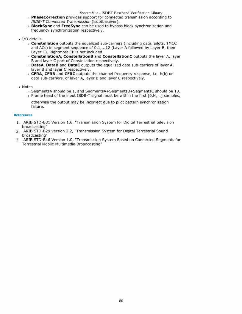
SystemVue - ISDBT Baseband Verification Library
80
PhaseCorrection provides support for connected transmission according toISDB-T Connected Transmission (isdbtbasever).BlockSync and FreqSync can be used to bypass block synchronization andfrequency synchronization respectively.
I/O detailsConstellation outputs the equalized sub-carriers (including data, pilots, TMCCand ACs) in segment sequence of 0,1,...12 (Layer A followed by Layer B, thenLayer C). Rightmost CP is not included.ConstellationA, ConstellationB and ConstellationC outputs the layer A, layerB and layer C part of Constellation respectively.DataA, DataB and DataC outputs the equalized data sub-carriers of layer A,layer B and layer C respectively.CFRA, CFRB and CFRC outputs the channel frequency response, i.e. h(k) ondata sub-carriers, of layer A, layer B and layer C respectively.
NotesSegmentsA should be 1, and SegmentsA+SegmentsB+SegmentsC should be 13.Frame head of the input ISDB-T signal must be within the first [0,NFFT] samples,
otherwise the output may be incorrect due to pilot pattern synchronizationfailure.
References
ARIB STD-B31 Version 1.6, "Transmission System for Digital Terrestrial television1.broadcasting" ARIB STD-B29 version 2.2, "Transmission System for Digital Terrestrial Sound2.Broadcasting" ARIB STD-B46 Version 1.0, "Transmission System Based on Connected Segments for3.Terrestrial Mobile Multimedia Broadcasting"
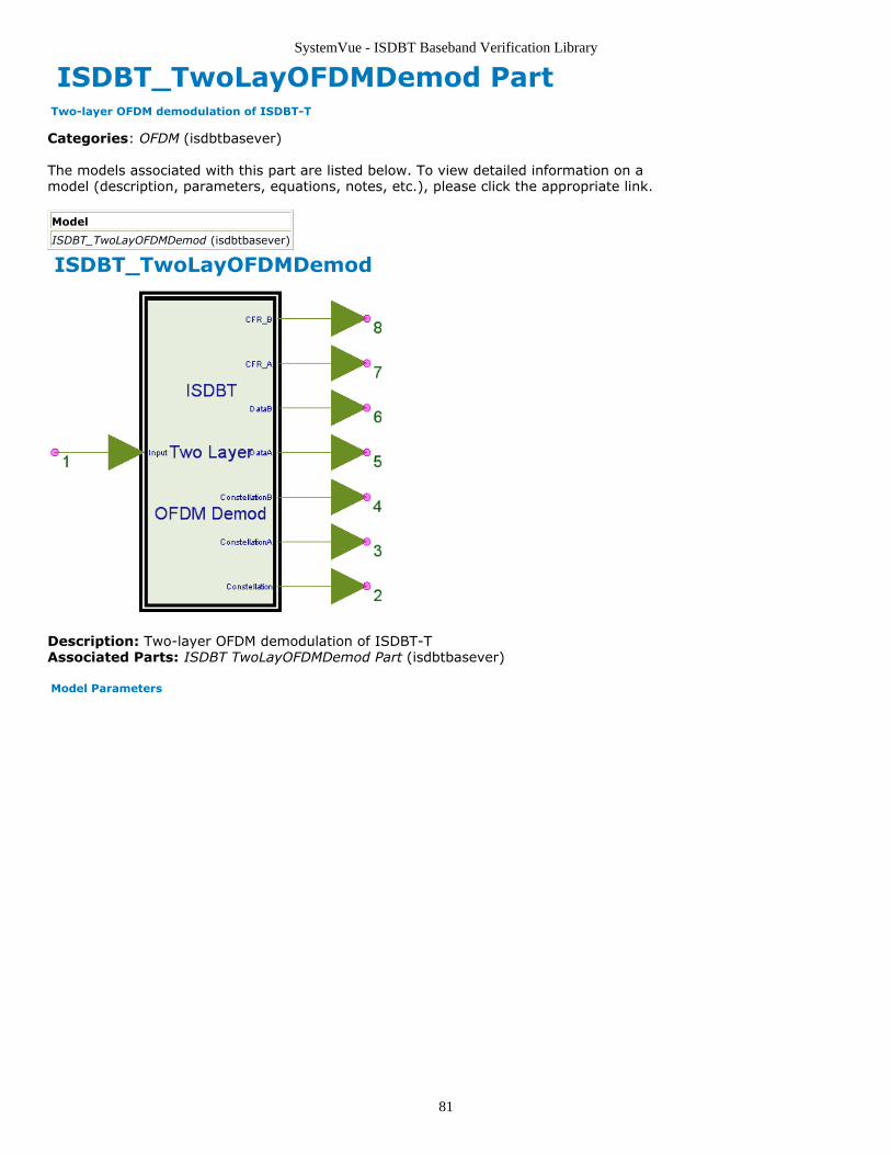
SystemVue - ISDBT Baseband Verification Library
81
ISDBT_TwoLayOFDMDemod Part Two-layer OFDM demodulation of ISDBT-T
Categories: OFDM (isdbtbasever)
The models associated with this part are listed below. To view detailed information on amodel (description, parameters, equations, notes, etc.), please click the appropriate link.
Model
ISDBT_TwoLayOFDMDemod (isdbtbasever)
ISDBT_TwoLayOFDMDemod
Description: Two-layer OFDM demodulation of ISDBT-TAssociated Parts: ISDBT TwoLayOFDMDemod Part (isdbtbasever)
Model Parameters
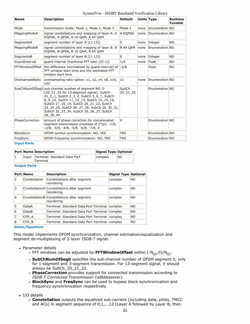
SystemVue - ISDBT Baseband Verification Library
82
Name Description Default Units Type RuntimeTunable
Mode transmission mode: Mode 1, Mode 2, Mode 3 Mode 1 none Enumeration NO
MappingModeA signal constellations and mapping of layer A: ADQPSK, A QPSK, A 16 QAM, A 64 QAM
A DQPSK none Enumeration NO
SegmentsA segment number of layer A ([1:13]) 5 none Integer NO
MappingModeB signal constellations and mapping of layer B: BDQPSK, B QPSK, B 16 QAM, B 64 QAM
B 64 QAM none Enumeration NO
SegmentsB segment number of layer B ([1:13]) 8 none Integer NO
GuardInterval guard interval (fractional FFT size) ([0:1]) 1/4 none Float NO
FFTWindowOffset the difference (normalized by guard interval) ofFFT window start time and the estimated FFTwindow start time
-3/8 Float NO
OversampleRatio oversampling ratio option: x1, x2, x4, x8, x16,x32
x1 none Enumeration NO
SubChNumOfSeg0 sub-channel number of segment NO. 0(20_21_22 for 13-segment signal): SubCh41_0_1, SubCh 2_3_4, SubCh 5_6_7, SubCh8_9_10, SubCh 11_12_13, SubCh 14_15_16,SubCh 17_18_19, SubCh 20_21_22, SubCh23_24_25, SubCh 26_27_28, SubCh 29_30_31,SubCh 32_33_34, SubCh 35_36_37, SubCh38_39_40
SubCh20_21_22
Enumeration NO
PhaseCorrection amount of phase correction for concatenatedsegment transmission (multiple of 2*pi): -1/8,-2/8, -3/8, -4/8, -5/8, -6/8, -7/8, 0
0 Enumeration NO
BlockSync OFDM symbol synchronization: NO, YES YES Enumeration NO
FreqSync OFDM frequency synchronization: NO, YES YES Enumeration NO
Input Ports
Port Name Description Signal Type Optional
1 Input Terminal: Standard Data PortTerminal
complex NO
Output Ports
Port Name Description Signal Type Optional
2 Constellation Constellations after segmentreordering
complex NO
3 ConstellationA Constellations after segmentreordering
complex NO
4 ConstellationB Constellations after segmentreordering
complex NO
5 DataA Terminal: Standard Data Port Terminal complex NO
6 DataB Terminal: Standard Data Port Terminal complex NO
7 CFR_A Terminal: Standard Data Port Terminal complex NO
8 CFR_B Terminal: Standard Data Port Terminal complex NO
Notes/Equations
This model implements OFDM synchronization, channel estimation/equalization andsegment de-multiplexing of 2-layer ISDB-T signal.
Parameter detailsFFT windows can be adjusted by FFTWindowOffset within [-NGI,0]/NGI.
SubChNumOfSeg0 specifies the sub-channel number of OFDM segment 0, onlyfor 1-segment and 3-segment transmission. For 13-segment signal, it shouldalways be SubCh_20_21_22.PhaseCorrection provides support for connected transmission according toISDB-T Connected Transmission (isdbtbasever).BlockSync and FreqSync can be used to bypass block synchronization andfrequency synchronization respectively.
I/O detailsConstellation outputs the equalized sub-carriers (including data, pilots, TMCCand ACs) in segment sequence of 0,1,...12 (Layer A followed by Layer B, then
SystemVue - ISDBT Baseband Verification Library
83
Layer C). Rightmost CP is not included.ConstellationA and ConstellationB outputs the layer A, layer B and layer Cpart of Constellation respectively.DataA and DataB outputs the equalized data sub-carriers of layer A and layer Brespectively.CFRA and CFRB outputs the channel frequency response, i.e. h(k) on data sub-carriers, of layer A and layer B respectively.
NotesSegmentsA+SegmentsB should be 13.Frame head of the input ISDB-T signal must be within the first [0,NFFT] samples,
otherwise the output may be incorrect due to pilot pattern synchronizationfailure.
References
ARIB STD-B31 Version 1.6, "Transmission System for Digital Terrestrial television1.broadcasting" ARIB STD-B29 version 2.2, "Transmission System for Digital Terrestrial Sound2.Broadcasting" ARIB STD-B46 Version 1.0, "Transmission System Based on Connected Segments for3.Terrestrial Mobile Multimedia Broadcasting"
SystemVue - ISDBT Baseband Verification Library
84
ISDBT Receiver Category Contents
ISDBT OneLayReceiver Part (isdbtbasever)ISDBT ThreeLayReceiver Part (isdbtbasever)ISDBT TwoLayReceiver Part (isdbtbasever)
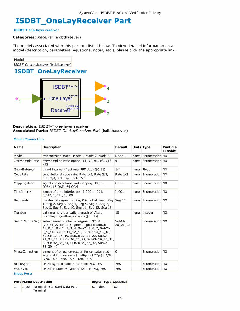
SystemVue - ISDBT Baseband Verification Library
85
ISDBT_OneLayReceiver Part ISDBT-T one-layer receiver
Categories: Receiver (isdbtbasever)
The models associated with this part are listed below. To view detailed information on amodel (description, parameters, equations, notes, etc.), please click the appropriate link.
Model
ISDBT_OneLayReceiver (isdbtbasever)
ISDBT_OneLayReceiver
Description: ISDBT-T one-layer receiverAssociated Parts: ISDBT OneLayReceiver Part (isdbtbasever)
Model Parameters
Name Description Default Units Type RuntimeTunable
Mode transmission mode: Mode 1, Mode 2, Mode 3 Mode 1 none Enumeration NO
OversampleRatio oversampling ratio option: x1, x2, x4, x8, x16,x32
x1 none Enumeration NO
GuardInterval guard interval (fractional FFT size) ([0:1]) 1/4 none Float NO
CodeRate convolutional code rate: Rate 1/2, Rate 2/3,Rate 3/4, Rate 5/6, Rate 7/8
Rate 1/2 none Enumeration NO
MappingMode signal constellations and mapping: DQPSK,QPSK, 16 QAM, 64 QAM
QPSK none Enumeration NO
TimeInterlv length of time interleaver: I_000, I_001,I_010, I_011, I_100
I_001 none Enumeration NO
Segments number of segments: Seg 0 is not allowed, Seg1, Seg 2, Seg 3, Seg 4, Seg 5, Seg 6, Seg 7,Seg 8, Seg 9, Seg 10, Seg 11, Seg 12, Seg 13
Seg 13 none Enumeration NO
TrunLen path memory truncation length of Viterbidecoding algorithm, in bytes ([5:inf))
10 none Integer NO
SubChNumOfSeg0 sub-channel number of segment NO. 0(20_21_22 for 13-segment signal): SubCh41_0_1, SubCh 2_3_4, SubCh 5_6_7, SubCh8_9_10, SubCh 11_12_13, SubCh 14_15_16,SubCh 17_18_19, SubCh 20_21_22, SubCh23_24_25, SubCh 26_27_28, SubCh 29_30_31,SubCh 32_33_34, SubCh 35_36_37, SubCh38_39_40
SubCh20_21_22
Enumeration NO
PhaseCorrection amount of phase correction for concatenatedsegment transmission (multiple of 2*pi): -1/8,-2/8, -3/8, -4/8, -5/8, -6/8, -7/8, 0
0 Enumeration NO
BlockSync OFDM symbol synchronization: NO, YES YES Enumeration NO
FreqSync OFDM frequency synchronization: NO, YES YES Enumeration NO
Input Ports
Port Name Description Signal Type Optional
1 Input Terminal: Standard Data PortTerminal
complex NO
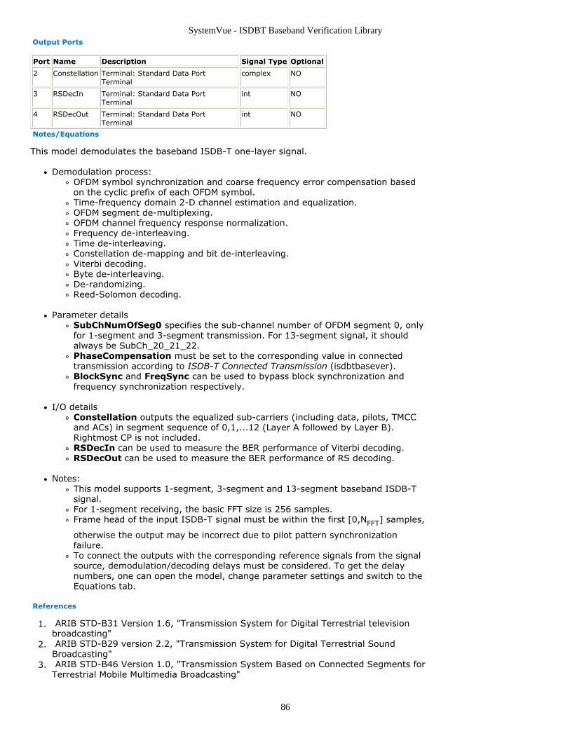
SystemVue - ISDBT Baseband Verification Library
86
Output Ports
Port Name Description Signal Type Optional
2 Constellation Terminal: Standard Data PortTerminal
complex NO
3 RSDecIn Terminal: Standard Data PortTerminal
int NO
4 RSDecOut Terminal: Standard Data PortTerminal
int NO
Notes/Equations
This model demodulates the baseband ISDB-T one-layer signal.
Demodulation process:OFDM symbol synchronization and coarse frequency error compensation basedon the cyclic prefix of each OFDM symbol.Time-frequency domain 2-D channel estimation and equalization.OFDM segment de-multiplexing.OFDM channel frequency response normalization.Frequency de-interleaving.Time de-interleaving.Constellation de-mapping and bit de-interleaving.Viterbi decoding.Byte de-interleaving.De-randomizing.Reed-Solomon decoding.
Parameter detailsSubChNumOfSeg0 specifies the sub-channel number of OFDM segment 0, onlyfor 1-segment and 3-segment transmission. For 13-segment signal, it shouldalways be SubCh_20_21_22.PhaseCompensation must be set to the corresponding value in connectedtransmission according to ISDB-T Connected Transmission (isdbtbasever).BlockSync and FreqSync can be used to bypass block synchronization andfrequency synchronization respectively.
I/O detailsConstellation outputs the equalized sub-carriers (including data, pilots, TMCCand ACs) in segment sequence of 0,1,...12 (Layer A followed by Layer B).Rightmost CP is not included.RSDecIn can be used to measure the BER performance of Viterbi decoding.RSDecOut can be used to measure the BER performance of RS decoding.
Notes:This model supports 1-segment, 3-segment and 13-segment baseband ISDB-Tsignal.For 1-segment receiving, the basic FFT size is 256 samples.Frame head of the input ISDB-T signal must be within the first [0,NFFT] samples,
otherwise the output may be incorrect due to pilot pattern synchronizationfailure.To connect the outputs with the corresponding reference signals from the signalsource, demodulation/decoding delays must be considered. To get the delaynumbers, one can open the model, change parameter settings and switch to theEquations tab.
References
ARIB STD-B31 Version 1.6, "Transmission System for Digital Terrestrial television1.broadcasting" ARIB STD-B29 version 2.2, "Transmission System for Digital Terrestrial Sound2.Broadcasting" ARIB STD-B46 Version 1.0, "Transmission System Based on Connected Segments for3.Terrestrial Mobile Multimedia Broadcasting"
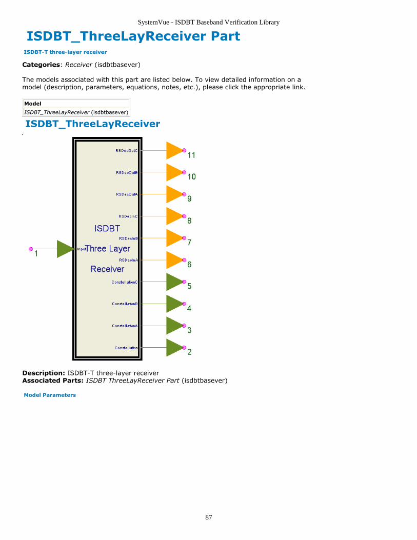
SystemVue - ISDBT Baseband Verification Library
87
ISDBT_ThreeLayReceiver Part ISDBT-T three-layer receiver
Categories: Receiver (isdbtbasever)
The models associated with this part are listed below. To view detailed information on amodel (description, parameters, equations, notes, etc.), please click the appropriate link.
Model
ISDBT_ThreeLayReceiver (isdbtbasever)
ISDBT_ThreeLayReceiver
Description: ISDBT-T three-layer receiverAssociated Parts: ISDBT ThreeLayReceiver Part (isdbtbasever)
Model Parameters
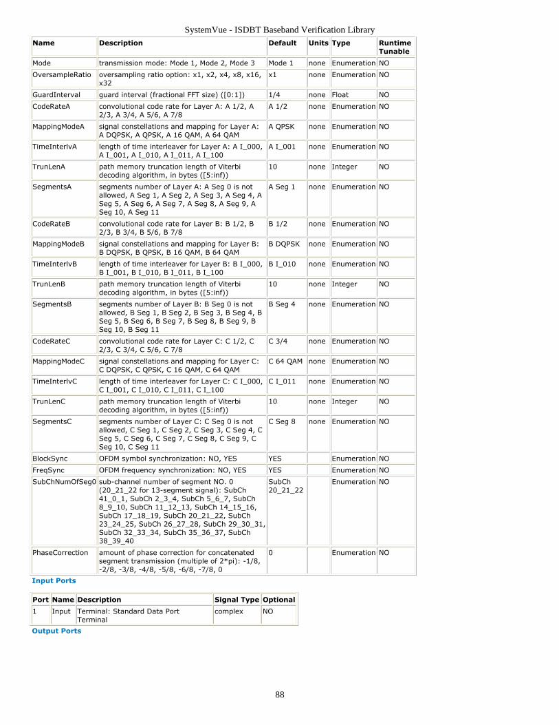
SystemVue - ISDBT Baseband Verification Library
88
Name Description Default Units Type RuntimeTunable
Mode transmission mode: Mode 1, Mode 2, Mode 3 Mode 1 none Enumeration NO
OversampleRatio oversampling ratio option: x1, x2, x4, x8, x16,x32
x1 none Enumeration NO
GuardInterval guard interval (fractional FFT size) ([0:1]) 1/4 none Float NO
CodeRateA convolutional code rate for Layer A: A 1/2, A2/3, A 3/4, A 5/6, A 7/8
A 1/2 none Enumeration NO
MappingModeA signal constellations and mapping for Layer A:A DQPSK, A QPSK, A 16 QAM, A 64 QAM
A QPSK none Enumeration NO
TimeInterlvA length of time interleaver for Layer A: A I_000,A I_001, A I_010, A I_011, A I_100
A I_001 none Enumeration NO
TrunLenA path memory truncation length of Viterbidecoding algorithm, in bytes ([5:inf))
10 none Integer NO
SegmentsA segments number of Layer A: A Seg 0 is notallowed, A Seg 1, A Seg 2, A Seg 3, A Seg 4, ASeg 5, A Seg 6, A Seg 7, A Seg 8, A Seg 9, ASeg 10, A Seg 11
A Seg 1 none Enumeration NO
CodeRateB convolutional code rate for Layer B: B 1/2, B2/3, B 3/4, B 5/6, B 7/8
B 1/2 none Enumeration NO
MappingModeB signal constellations and mapping for Layer B:B DQPSK, B QPSK, B 16 QAM, B 64 QAM
B DQPSK none Enumeration NO
TimeInterlvB length of time interleaver for Layer B: B I_000,B I_001, B I_010, B I_011, B I_100
B I_010 none Enumeration NO
TrunLenB path memory truncation length of Viterbidecoding algorithm, in bytes ([5:inf))
10 none Integer NO
SegmentsB segments number of Layer B: B Seg 0 is notallowed, B Seg 1, B Seg 2, B Seg 3, B Seg 4, BSeg 5, B Seg 6, B Seg 7, B Seg 8, B Seg 9, BSeg 10, B Seg 11
B Seg 4 none Enumeration NO
CodeRateC convolutional code rate for Layer C: C 1/2, C2/3, C 3/4, C 5/6, C 7/8
C 3/4 none Enumeration NO
MappingModeC signal constellations and mapping for Layer C:C DQPSK, C QPSK, C 16 QAM, C 64 QAM
C 64 QAM none Enumeration NO
TimeInterlvC length of time interleaver for Layer C: C I_000,C I_001, C I_010, C I_011, C I_100
C I_011 none Enumeration NO
TrunLenC path memory truncation length of Viterbidecoding algorithm, in bytes ([5:inf))
10 none Integer NO
SegmentsC segments number of Layer C: C Seg 0 is notallowed, C Seg 1, C Seg 2, C Seg 3, C Seg 4, CSeg 5, C Seg 6, C Seg 7, C Seg 8, C Seg 9, CSeg 10, C Seg 11
C Seg 8 none Enumeration NO
BlockSync OFDM symbol synchronization: NO, YES YES Enumeration NO
FreqSync OFDM frequency synchronization: NO, YES YES Enumeration NO
SubChNumOfSeg0 sub-channel number of segment NO. 0(20_21_22 for 13-segment signal): SubCh41_0_1, SubCh 2_3_4, SubCh 5_6_7, SubCh8_9_10, SubCh 11_12_13, SubCh 14_15_16,SubCh 17_18_19, SubCh 20_21_22, SubCh23_24_25, SubCh 26_27_28, SubCh 29_30_31,SubCh 32_33_34, SubCh 35_36_37, SubCh38_39_40
SubCh20_21_22
Enumeration NO
PhaseCorrection amount of phase correction for concatenatedsegment transmission (multiple of 2*pi): -1/8,-2/8, -3/8, -4/8, -5/8, -6/8, -7/8, 0
0 Enumeration NO
Input Ports
Port Name Description Signal Type Optional
1 Input Terminal: Standard Data PortTerminal
complex NO
Output Ports
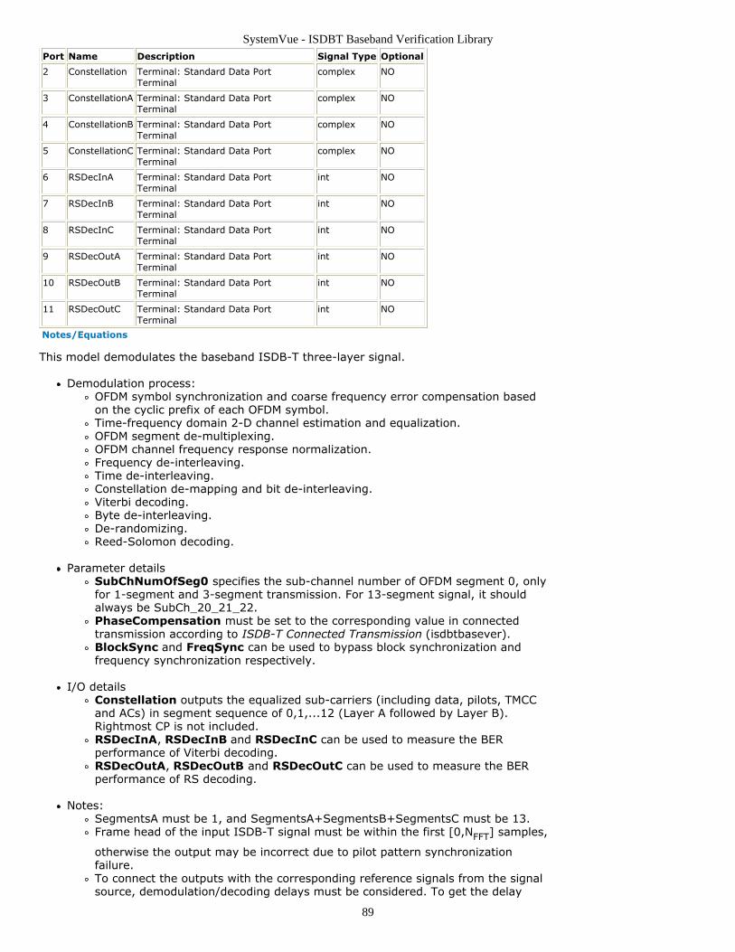
SystemVue - ISDBT Baseband Verification Library
89
Port Name Description Signal Type Optional
2 Constellation Terminal: Standard Data PortTerminal
complex NO
3 ConstellationA Terminal: Standard Data PortTerminal
complex NO
4 ConstellationB Terminal: Standard Data PortTerminal
complex NO
5 ConstellationC Terminal: Standard Data PortTerminal
complex NO
6 RSDecInA Terminal: Standard Data PortTerminal
int NO
7 RSDecInB Terminal: Standard Data PortTerminal
int NO
8 RSDecInC Terminal: Standard Data PortTerminal
int NO
9 RSDecOutA Terminal: Standard Data PortTerminal
int NO
10 RSDecOutB Terminal: Standard Data PortTerminal
int NO
11 RSDecOutC Terminal: Standard Data PortTerminal
int NO
Notes/Equations
This model demodulates the baseband ISDB-T three-layer signal.
Demodulation process:OFDM symbol synchronization and coarse frequency error compensation basedon the cyclic prefix of each OFDM symbol.Time-frequency domain 2-D channel estimation and equalization.OFDM segment de-multiplexing.OFDM channel frequency response normalization.Frequency de-interleaving.Time de-interleaving.Constellation de-mapping and bit de-interleaving.Viterbi decoding.Byte de-interleaving.De-randomizing.Reed-Solomon decoding.
Parameter detailsSubChNumOfSeg0 specifies the sub-channel number of OFDM segment 0, onlyfor 1-segment and 3-segment transmission. For 13-segment signal, it shouldalways be SubCh_20_21_22.PhaseCompensation must be set to the corresponding value in connectedtransmission according to ISDB-T Connected Transmission (isdbtbasever).BlockSync and FreqSync can be used to bypass block synchronization andfrequency synchronization respectively.
I/O detailsConstellation outputs the equalized sub-carriers (including data, pilots, TMCCand ACs) in segment sequence of 0,1,...12 (Layer A followed by Layer B).Rightmost CP is not included.RSDecInA, RSDecInB and RSDecInC can be used to measure the BERperformance of Viterbi decoding.RSDecOutA, RSDecOutB and RSDecOutC can be used to measure the BERperformance of RS decoding.
Notes:SegmentsA must be 1, and SegmentsA+SegmentsB+SegmentsC must be 13.Frame head of the input ISDB-T signal must be within the first [0,NFFT] samples,
otherwise the output may be incorrect due to pilot pattern synchronizationfailure.To connect the outputs with the corresponding reference signals from the signalsource, demodulation/decoding delays must be considered. To get the delay
SystemVue - ISDBT Baseband Verification Library
90
numbers, one can open the model, change parameter settings and switch to theEquations tab.
References
ARIB STD-B31 Version 1.6, "Transmission System for Digital Terrestrial television1.broadcasting" ARIB STD-B29 version 2.2, "Transmission System for Digital Terrestrial Sound2.Broadcasting" ARIB STD-B46 Version 1.0, "Transmission System Based on Connected Segments for3.Terrestrial Mobile Multimedia Broadcasting"
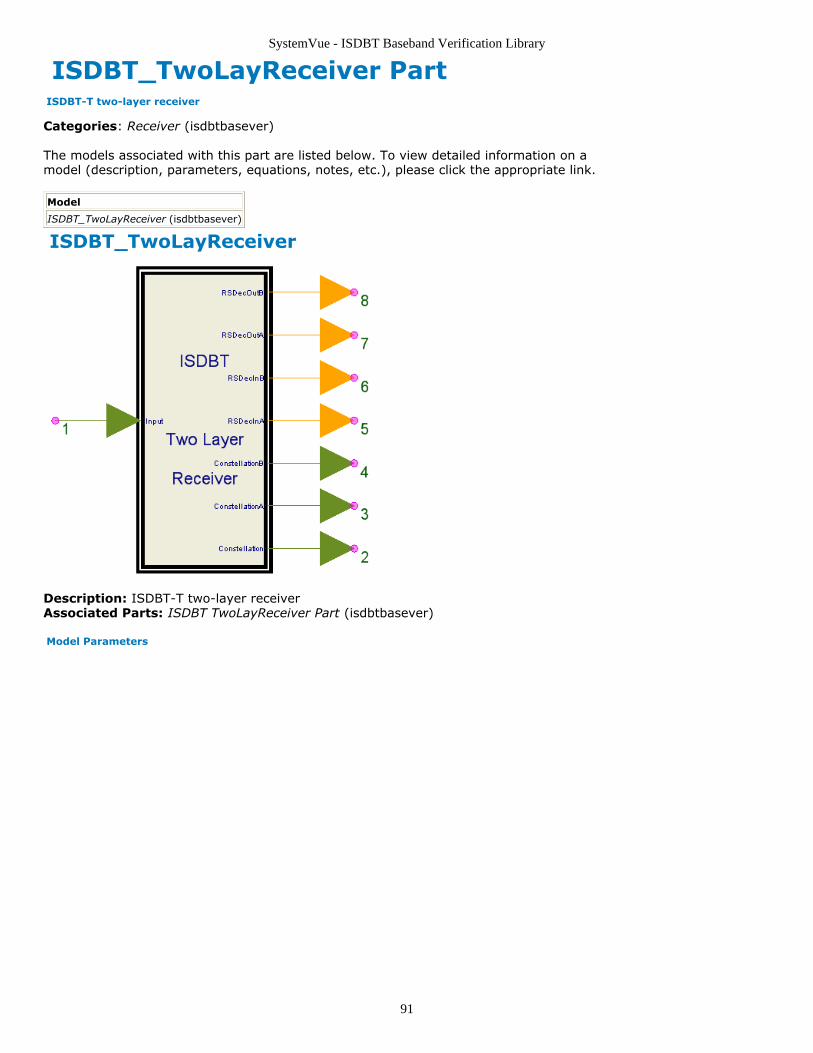
SystemVue - ISDBT Baseband Verification Library
91
ISDBT_TwoLayReceiver Part ISDBT-T two-layer receiver
Categories: Receiver (isdbtbasever)
The models associated with this part are listed below. To view detailed information on amodel (description, parameters, equations, notes, etc.), please click the appropriate link.
Model
ISDBT_TwoLayReceiver (isdbtbasever)
ISDBT_TwoLayReceiver
Description: ISDBT-T two-layer receiverAssociated Parts: ISDBT TwoLayReceiver Part (isdbtbasever)
Model Parameters
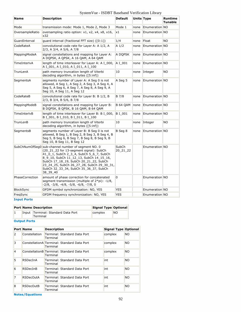
SystemVue - ISDBT Baseband Verification Library
92
Name Description Default Units Type RuntimeTunable
Mode transmission mode: Mode 1, Mode 2, Mode 3 Mode 1 none Enumeration NO
OversampleRatio oversampling ratio option: x1, x2, x4, x8, x16,x32
x1 none Enumeration NO
GuardInterval guard interval (fractional FFT size) ([0:1]) 1/4 none Float NO
CodeRateA convolutional code rate for Layer A: A 1/2, A2/3, A 3/4, A 5/6, A 7/8
A 1/2 none Enumeration NO
MappingModeA signal constellations and mapping for Layer A:A DQPSK, A QPSK, A 16 QAM, A 64 QAM
A DQPSK none Enumeration NO
TimeInterlvA length of time interleaver for Layer A: A I_000,A I_001, A I_010, A I_011, A I_100
A I_001 none Enumeration NO
TrunLenA path memory truncation length of Viterbidecoding algorithm, in bytes ([5:inf))
10 none Integer NO
SegmentsA segments number of Layer A: A Seg 0 is notallowed, A Seg 1, A Seg 2, A Seg 3, A Seg 4, ASeg 5, A Seg 6, A Seg 7, A Seg 8, A Seg 9, ASeg 10, A Seg 11, A Seg 12
A Seg 5 none Enumeration NO
CodeRateB convolutional code rate for Layer B: B 1/2, B2/3, B 3/4, B 5/6, B 7/8
B 7/8 none Enumeration NO
MappingModeB signal constellations and mapping for Layer B:B DQPSK, B QPSK, B 16 QAM, B 64 QAM
B 64 QAM none Enumeration NO
TimeInterlvB length of time interleaver for Layer B: B I_000,B I_001, B I_010, B I_011, B I_100
B I_001 none Enumeration NO
TrunLenB path memory truncation length of Viterbidecoding algorithm, in bytes ([5:inf))
10 none Integer NO
SegmentsB segments number of Layer B: B Seg 0 is notallowed, B Seg 1, B Seg 2, B Seg 3, B Seg 4, BSeg 5, B Seg 6, B Seg 7, B Seg 8, B Seg 9, BSeg 10, B Seg 11, B Seg 12
B Seg 8 none Enumeration NO
SubChNumOfSeg0 sub-channel number of segment NO. 0(20_21_22 for 13-segment signal): SubCh41_0_1, SubCh 2_3_4, SubCh 5_6_7, SubCh8_9_10, SubCh 11_12_13, SubCh 14_15_16,SubCh 17_18_19, SubCh 20_21_22, SubCh23_24_25, SubCh 26_27_28, SubCh 29_30_31,SubCh 32_33_34, SubCh 35_36_37, SubCh38_39_40
SubCh20_21_22
Enumeration NO
PhaseCorrection amount of phase correction for concatenatedsegment transmission (multiple of 2*pi): -1/8,-2/8, -3/8, -4/8, -5/8, -6/8, -7/8, 0
0 Enumeration NO
BlockSync OFDM symbol synchronization: NO, YES YES Enumeration NO
FreqSync OFDM frequency synchronization: NO, YES YES Enumeration NO
Input Ports
Port Name Description Signal Type Optional
1 Input Terminal: Standard Data PortTerminal
complex NO
Output Ports
Port Name Description Signal Type Optional
2 Constellation Terminal: Standard Data PortTerminal
complex NO
3 ConstellationA Terminal: Standard Data PortTerminal
complex NO
4 ConstellationB Terminal: Standard Data PortTerminal
complex NO
5 RSDecInA Terminal: Standard Data PortTerminal
int NO
6 RSDecInB Terminal: Standard Data PortTerminal
int NO
7 RSDecOutA Terminal: Standard Data PortTerminal
int NO
8 RSDecOutB Terminal: Standard Data PortTerminal
int NO
Notes/Equations
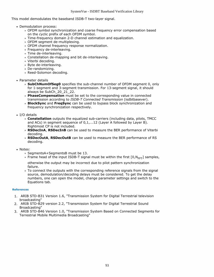
SystemVue - ISDBT Baseband Verification Library
93
This model demodulates the baseband ISDB-T two-layer signal.
Demodulation process:OFDM symbol synchronization and coarse frequency error compensation basedon the cyclic prefix of each OFDM symbol.Time-frequency domain 2-D channel estimation and equalization.OFDM segment de-multiplexing.OFDM channel frequency response normalization.Frequency de-interleaving.Time de-interleaving.Constellation de-mapping and bit de-interleaving.Viterbi decoding.Byte de-interleaving.De-randomizing.Reed-Solomon decoding.
Parameter detailsSubChNumOfSeg0 specifies the sub-channel number of OFDM segment 0, onlyfor 1-segment and 3-segment transmission. For 13-segment signal, it shouldalways be SubCh_20_21_22.PhaseCompensation must be set to the corresponding value in connectedtransmission according to ISDB-T Connected Transmission (isdbtbasever).BlockSync and FreqSync can be used to bypass block synchronization andfrequency synchronization respectively.
I/O detailsConstellation outputs the equalized sub-carriers (including data, pilots, TMCCand ACs) in segment sequence of 0,1,...12 (Layer A followed by Layer B).Rightmost CP is not included.RSDecInA, RSDecInB can be used to measure the BER performance of Viterbidecoding.RSDecOutA, RSDecOutB can be used to measure the BER performance of RSdecoding.
Notes:SegmentsA+SegmentsB must be 13.Frame head of the input ISDB-T signal must be within the first [0,NFFT] samples,
otherwise the output may be incorrect due to pilot pattern synchronizationfailure.To connect the outputs with the corresponding reference signals from the signalsource, demodulation/decoding delays must be considered. To get the delaynumbers, one can open the model, change parameter settings and switch to theEquations tab.
References
ARIB STD-B31 Version 1.6, "Transmission System for Digital Terrestrial television1.broadcasting" ARIB STD-B29 version 2.2, "Transmission System for Digital Terrestrial Sound2.Broadcasting" ARIB STD-B46 Version 1.0, "Transmission System Based on Connected Segments for3.Terrestrial Mobile Multimedia Broadcasting"
SystemVue - ISDBT Baseband Verification Library
94
ISDBT Source Category Contents
ISDBT OneLaySource Part (isdbtbasever)ISDBT ThreeLaySource Part (isdbtbasever)ISDBT TmmSource Part (isdbtbasever)ISDBT TsbSource Part (isdbtbasever)ISDBT TSPSource Part (isdbtbasever)ISDBT TwoLaySource Part (isdbtbasever)
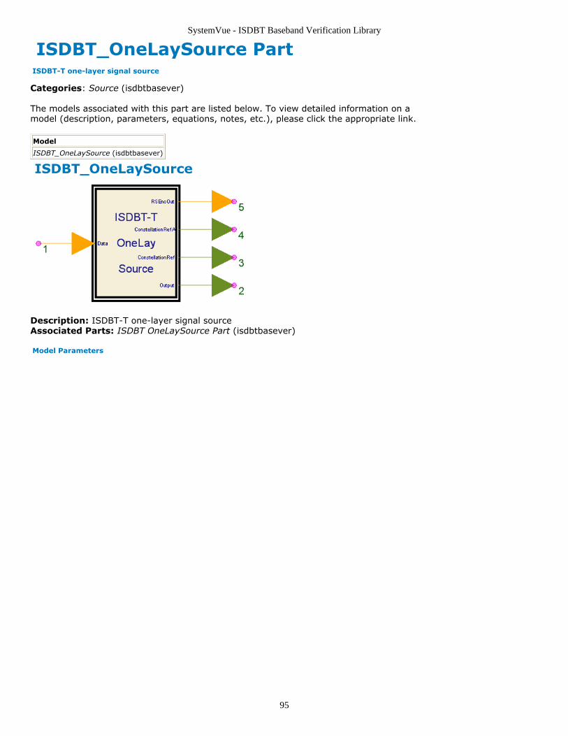
SystemVue - ISDBT Baseband Verification Library
95
ISDBT_OneLaySource Part ISDBT-T one-layer signal source
Categories: Source (isdbtbasever)
The models associated with this part are listed below. To view detailed information on amodel (description, parameters, equations, notes, etc.), please click the appropriate link.
Model
ISDBT_OneLaySource (isdbtbasever)
ISDBT_OneLaySource
Description: ISDBT-T one-layer signal sourceAssociated Parts: ISDBT OneLaySource Part (isdbtbasever)
Model Parameters
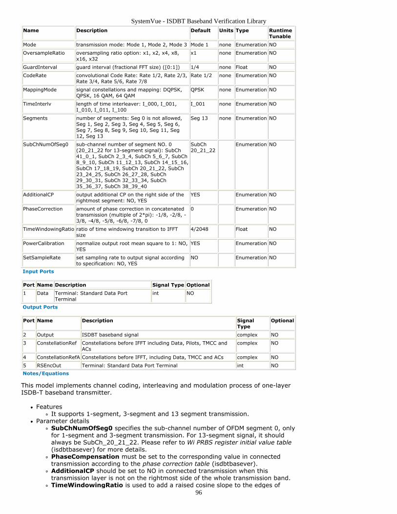
SystemVue - ISDBT Baseband Verification Library
96
Name Description Default Units Type RuntimeTunable
Mode transmission mode: Mode 1, Mode 2, Mode 3 Mode 1 none Enumeration NO
OversampleRatio oversampling ratio option: x1, x2, x4, x8,x16, x32
x1 none Enumeration NO
GuardInterval guard interval (fractional FFT size) ([0:1]) 1/4 none Float NO
CodeRate convolutional Code Rate: Rate 1/2, Rate 2/3,Rate 3/4, Rate 5/6, Rate 7/8
Rate 1/2 none Enumeration NO
MappingMode signal constellations and mapping: DQPSK,QPSK, 16 QAM, 64 QAM
QPSK none Enumeration NO
TimeInterlv length of time interleaver: I_000, I_001,I_010, I_011, I_100
I_001 none Enumeration NO
Segments number of segments: Seg 0 is not allowed,Seg 1, Seg 2, Seg 3, Seg 4, Seg 5, Seg 6,Seg 7, Seg 8, Seg 9, Seg 10, Seg 11, Seg12, Seg 13
Seg 13 none Enumeration NO
SubChNumOfSeg0 sub-channel number of segment NO. 0(20_21_22 for 13-segment signal): SubCh41_0_1, SubCh 2_3_4, SubCh 5_6_7, SubCh8_9_10, SubCh 11_12_13, SubCh 14_15_16,SubCh 17_18_19, SubCh 20_21_22, SubCh23_24_25, SubCh 26_27_28, SubCh29_30_31, SubCh 32_33_34, SubCh35_36_37, SubCh 38_39_40
SubCh20_21_22
Enumeration NO
AdditionalCP output additional CP on the right side of therightmost segment: NO, YES
YES Enumeration NO
PhaseCorrection amount of phase correction in concatenatedtransmission (multiple of 2*pi): -1/8, -2/8, -3/8, -4/8, -5/8, -6/8, -7/8, 0
0 Enumeration NO
TimeWindowingRatio ratio of time windowing transition to IFFTsize
4/2048 Float NO
PowerCalibration normalize output root mean square to 1: NO,YES
YES Enumeration NO
SetSampleRate set sampling rate to output signal accordingto specification: NO, YES
NO Enumeration NO
Input Ports
Port Name Description Signal Type Optional
1 Data Terminal: Standard Data PortTerminal
int NO
Output Ports
Port Name Description SignalType
Optional
2 Output ISDBT baseband signal complex NO
3 ConstellationRef Constellations before IFFT including Data, Pilots, TMCC andACs
complex NO
4 ConstellationRefA Constellations before IFFT, including Data, TMCC and ACs complex NO
5 RSEncOut Terminal: Standard Data Port Terminal int NO
Notes/Equations
This model implements channel coding, interleaving and modulation process of one-layerISDB-T baseband transmitter.
FeaturesIt supports 1-segment, 3-segment and 13 segment transmission.
Parameter detailsSubChNumOfSeg0 specifies the sub-channel number of OFDM segment 0, onlyfor 1-segment and 3-segment transmission. For 13-segment signal, it shouldalways be SubCh_20_21_22. Please refer to Wi PRBS register initial value table(isdbtbasever) for more details.PhaseCompensation must be set to the corresponding value in connectedtransmission according to the phase correction table (isdbtbasever).AdditionalCP should be set to NO in connected transmission when thistransmission layer is not on the rightmost side of the whole transmission band.TimeWindowingRatio is used to add a raised cosine slope to the edges of
SystemVue - ISDBT Baseband Verification Library
97
each OFDM symbol so as to reduce out-of-band power leakage. The valueshould generally much smaller than GI ratio (the ratio of guard interval to FFTinterval).PowerCalibration is used to normalize the rms (root mean square) ofbaseband signal to 1.SetSampleRate is used to add sampling rate information to output signal.
I/O detailsData must be 188-byte TS packets in the form of bytes.ConstellationRef, in the OFDM segment sequence of [11,9,...,1,0,2,...,10,12],can be used to measure the RMSE (or EVM) of the modulated signal.ConstellationRefA is in the OFDM segment sequence of [0,1,2,...,11,12].RSEncOut can be used to measure the BER performance of Viterbi decoding.
References
ARIB STD-B31 Version 1.6, "Transmission System for Digital Terrestrial television1.broadcasting" ARIB STD-B29 version 2.2, "Transmission System for Digital Terrestrial Sound2.Broadcasting" ARIB STD-B46 Version 1.0, "Transmission System Based on Connected Segments for3.Terrestrial Mobile Multimedia Broadcasting"
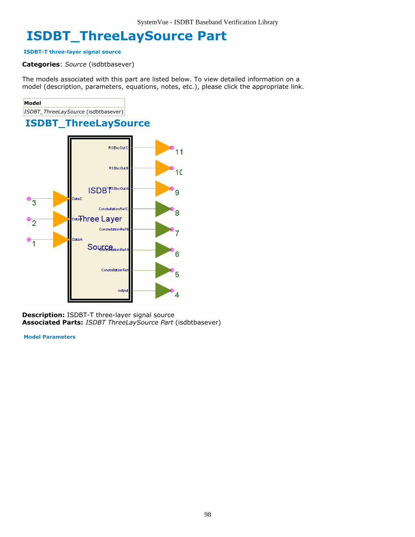
SystemVue - ISDBT Baseband Verification Library
98
ISDBT_ThreeLaySource Part ISDBT-T three-layer signal source
Categories: Source (isdbtbasever)
The models associated with this part are listed below. To view detailed information on amodel (description, parameters, equations, notes, etc.), please click the appropriate link.
Model
ISDBT_ThreeLaySource (isdbtbasever)
ISDBT_ThreeLaySource
Description: ISDBT-T three-layer signal sourceAssociated Parts: ISDBT ThreeLaySource Part (isdbtbasever)
Model Parameters
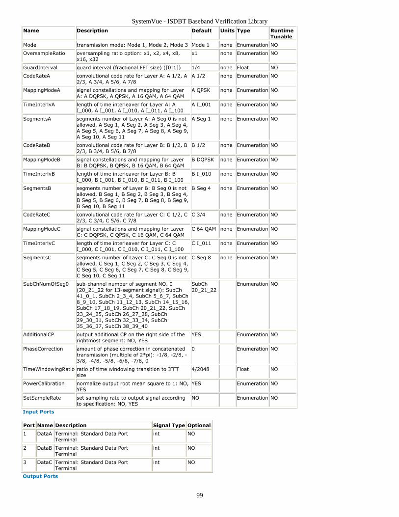
SystemVue - ISDBT Baseband Verification Library
99
Name Description Default Units Type RuntimeTunable
Mode transmission mode: Mode 1, Mode 2, Mode 3 Mode 1 none Enumeration NO
OversampleRatio oversampling ratio option: x1, x2, x4, x8,x16, x32
x1 none Enumeration NO
GuardInterval guard interval (fractional FFT size) ([0:1]) 1/4 none Float NO
CodeRateA convolutional code rate for Layer A: A 1/2, A2/3, A 3/4, A 5/6, A 7/8
A 1/2 none Enumeration NO
MappingModeA signal constellations and mapping for LayerA: A DQPSK, A QPSK, A 16 QAM, A 64 QAM
A QPSK none Enumeration NO
TimeInterlvA length of time interleaver for Layer A: AI_000, A I_001, A I_010, A I_011, A I_100
A I_001 none Enumeration NO
SegmentsA segments number of Layer A: A Seg 0 is notallowed, A Seg 1, A Seg 2, A Seg 3, A Seg 4,A Seg 5, A Seg 6, A Seg 7, A Seg 8, A Seg 9,A Seg 10, A Seg 11
A Seg 1 none Enumeration NO
CodeRateB convolutional code rate for Layer B: B 1/2, B2/3, B 3/4, B 5/6, B 7/8
B 1/2 none Enumeration NO
MappingModeB signal constellations and mapping for LayerB: B DQPSK, B QPSK, B 16 QAM, B 64 QAM
B DQPSK none Enumeration NO
TimeInterlvB length of time interleaver for Layer B: BI_000, B I_001, B I_010, B I_011, B I_100
B I_010 none Enumeration NO
SegmentsB segments number of Layer B: B Seg 0 is notallowed, B Seg 1, B Seg 2, B Seg 3, B Seg 4,B Seg 5, B Seg 6, B Seg 7, B Seg 8, B Seg 9,B Seg 10, B Seg 11
B Seg 4 none Enumeration NO
CodeRateC convolutional code rate for Layer C: C 1/2, C2/3, C 3/4, C 5/6, C 7/8
C 3/4 none Enumeration NO
MappingModeC signal constellations and mapping for LayerC: C DQPSK, C QPSK, C 16 QAM, C 64 QAM
C 64 QAM none Enumeration NO
TimeInterlvC length of time interleaver for Layer C: CI_000, C I_001, C I_010, C I_011, C I_100
C I_011 none Enumeration NO
SegmentsC segments number of Layer C: C Seg 0 is notallowed, C Seg 1, C Seg 2, C Seg 3, C Seg 4,C Seg 5, C Seg 6, C Seg 7, C Seg 8, C Seg 9,C Seg 10, C Seg 11
C Seg 8 none Enumeration NO
SubChNumOfSeg0 sub-channel number of segment NO. 0(20_21_22 for 13-segment signal): SubCh41_0_1, SubCh 2_3_4, SubCh 5_6_7, SubCh8_9_10, SubCh 11_12_13, SubCh 14_15_16,SubCh 17_18_19, SubCh 20_21_22, SubCh23_24_25, SubCh 26_27_28, SubCh29_30_31, SubCh 32_33_34, SubCh35_36_37, SubCh 38_39_40
SubCh20_21_22
Enumeration NO
AdditionalCP output additional CP on the right side of therightmost segment: NO, YES
YES Enumeration NO
PhaseCorrection amount of phase correction in concatenatedtransmission (multiple of 2*pi): -1/8, -2/8, -3/8, -4/8, -5/8, -6/8, -7/8, 0
0 Enumeration NO
TimeWindowingRatio ratio of time windowing transition to IFFTsize
4/2048 Float NO
PowerCalibration normalize output root mean square to 1: NO,YES
YES Enumeration NO
SetSampleRate set sampling rate to output signal accordingto specification: NO, YES
NO Enumeration NO
Input Ports
Port Name Description Signal Type Optional
1 DataA Terminal: Standard Data PortTerminal
int NO
2 DataB Terminal: Standard Data PortTerminal
int NO
3 DataC Terminal: Standard Data PortTerminal
int NO
Output Ports
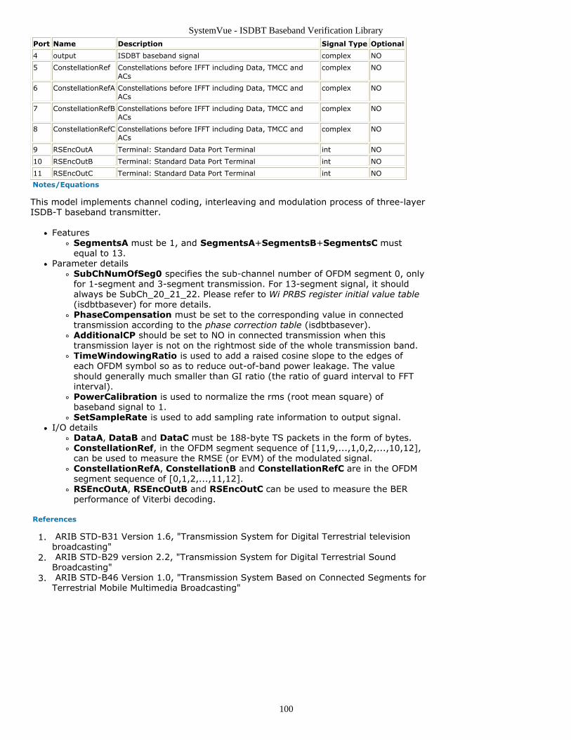
SystemVue - ISDBT Baseband Verification Library
100
Port Name Description Signal Type Optional
4 output ISDBT baseband signal complex NO
5 ConstellationRef Constellations before IFFT including Data, TMCC andACs
complex NO
6 ConstellationRefA Constellations before IFFT including Data, TMCC andACs
complex NO
7 ConstellationRefB Constellations before IFFT including Data, TMCC andACs
complex NO
8 ConstellationRefC Constellations before IFFT including Data, TMCC andACs
complex NO
9 RSEncOutA Terminal: Standard Data Port Terminal int NO
10 RSEncOutB Terminal: Standard Data Port Terminal int NO
11 RSEncOutC Terminal: Standard Data Port Terminal int NO
Notes/Equations
This model implements channel coding, interleaving and modulation process of three-layerISDB-T baseband transmitter.
FeaturesSegmentsA must be 1, and SegmentsA+SegmentsB+SegmentsC mustequal to 13.
Parameter detailsSubChNumOfSeg0 specifies the sub-channel number of OFDM segment 0, onlyfor 1-segment and 3-segment transmission. For 13-segment signal, it shouldalways be SubCh_20_21_22. Please refer to Wi PRBS register initial value table(isdbtbasever) for more details.PhaseCompensation must be set to the corresponding value in connectedtransmission according to the phase correction table (isdbtbasever).AdditionalCP should be set to NO in connected transmission when thistransmission layer is not on the rightmost side of the whole transmission band.TimeWindowingRatio is used to add a raised cosine slope to the edges ofeach OFDM symbol so as to reduce out-of-band power leakage. The valueshould generally much smaller than GI ratio (the ratio of guard interval to FFTinterval).PowerCalibration is used to normalize the rms (root mean square) ofbaseband signal to 1.SetSampleRate is used to add sampling rate information to output signal.
I/O detailsDataA, DataB and DataC must be 188-byte TS packets in the form of bytes.ConstellationRef, in the OFDM segment sequence of [11,9,...,1,0,2,...,10,12],can be used to measure the RMSE (or EVM) of the modulated signal.ConstellationRefA, ConstellationB and ConstellationRefC are in the OFDMsegment sequence of [0,1,2,...,11,12].RSEncOutA, RSEncOutB and RSEncOutC can be used to measure the BERperformance of Viterbi decoding.
References
ARIB STD-B31 Version 1.6, "Transmission System for Digital Terrestrial television1.broadcasting" ARIB STD-B29 version 2.2, "Transmission System for Digital Terrestrial Sound2.Broadcasting" ARIB STD-B46 Version 1.0, "Transmission System Based on Connected Segments for3.Terrestrial Mobile Multimedia Broadcasting"
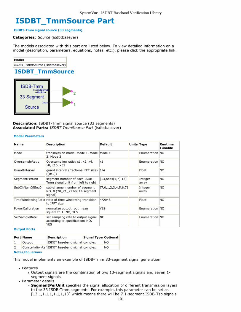
SystemVue - ISDBT Baseband Verification Library
101
ISDBT_TmmSource Part ISDBT-Tmm signal source (33 segments)
Categories: Source (isdbtbasever)
The models associated with this part are listed below. To view detailed information on amodel (description, parameters, equations, notes, etc.), please click the appropriate link.
Model
ISDBT_TmmSource (isdbtbasever)
ISDBT_TmmSource
Description: ISDBT-Tmm signal source (33 segments)Associated Parts: ISDBT TmmSource Part (isdbtbasever)
Model Parameters
Name Description Default Units Type RuntimeTunable
Mode transmission mode: Mode 1, Mode2, Mode 3
Mode 1 Enumeration NO
OversampleRatio Oversampling ratio: x1, x2, x4,x8, x16, x32
x1 Enumeration NO
GuardInterval guard interval (fractional FFT size)([0:1])
1/4 Float NO
SegmentPerUnit segment number of each ISDBT-Tmm signal unit from left to right
[13,ones(1,7),13] Integerarray
NO
SubChNumOfSeg0 sub-channel number of segmentNO. 0 (20_21_22 for 13-segmentsignal)
[7,0,1,2,3,4,5,6,7] Integerarray
NO
TimeWindowingRatio ratio of time windowing transitionto IFFT size
4/2048 Float NO
PowerCalibration normalize output root meansquare to 1: NO, YES
YES Enumeration NO
SetSampleRate set sampling rate to output signalaccording to specification: NO,YES
NO Enumeration NO
Output Ports
Port Name Description Signal Type Optional
1 Output ISDBT baseband signal complex NO
2 ConstellationRef ISDBT baseband signal complex NO
Notes/Equations
This model implements an example of ISDB-Tmm 33-segment signal generation.
FeaturesOutput signals are the combination of two 13-segment signals and seven 1-segment signals
Parameter detailsSegmentPerUnit specifies the signal allocation of different transmission layersto the 33 ISDB-Tmm segments. For example, this parameter can be set as[13,1,1,1,1,1,1,1,13] which means there will be 7 1-segment ISDB-Tsb signals

SystemVue - ISDBT Baseband Verification Library
102
and 2 13-segment ISDB-T signal on both sides respectively.SubChNumOfSeg0 specifies the sub-channel numbers of OFDM segment 0 ofthe connectedly transmitted layers. For the two 13-segment signals, it shouldalways be 7 (20_21_22). If SegmentPerUnit is set as [13,1,1,1,1,1,1,1,13],SubChNumOfSeg0 can be set as [7,0,1,2,3,4,5,6,7].Please refer to Wi PRBS register initial value table (isdbtbasever) for moredetails.TimeWindowingRatio is used to add a raised cosine slope to the edges ofeach OFDM symbol so as to reduce out-of-band power leakage. The valueshould generally much smaller than GI ratio (the ratio of guard interval to FFTinterval).PowerCalibration is used to normalize the rms (root mean square) ofbaseband signal to 1.SetSampleRate is used to add sampling rate information to output signal.
References
ARIB STD-B31 Version 1.6, "Transmission System for Digital Terrestrial television1.broadcasting" ARIB STD-B29 version 2.2, "Transmission System for Digital Terrestrial Sound2.Broadcasting" ARIB STD-B46 Version 1.0, "Transmission System Based on Connected Segments for3.Terrestrial Mobile Multimedia Broadcasting"
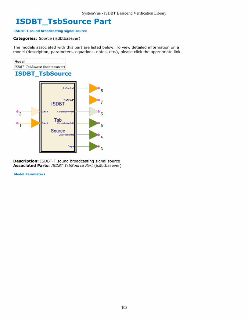
SystemVue - ISDBT Baseband Verification Library
103
ISDBT_TsbSource Part ISDBT-T sound broadcasting signal source
Categories: Source (isdbtbasever)
The models associated with this part are listed below. To view detailed information on amodel (description, parameters, equations, notes, etc.), please click the appropriate link.
Model
ISDBT_TsbSource (isdbtbasever)
ISDBT_TsbSource
Description: ISDBT-T sound broadcasting signal sourceAssociated Parts: ISDBT TsbSource Part (isdbtbasever)
Model Parameters
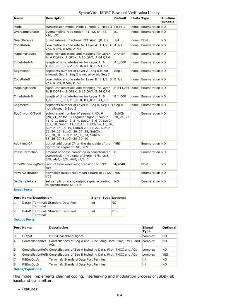
SystemVue - ISDBT Baseband Verification Library
104
Name Description Default Units Type RuntimeTunable
Mode transmission mode: Mode 1, Mode 2, Mode 3 Mode 1 none Enumeration NO
OversampleRatio oversampling ratio option: x1, x2, x4, x8,x16, x32
x1 none Enumeration NO
GuardInterval guard interval (fractional FFT size) ([0:1]) 1/4 none Float NO
CodeRateA convolutional code rate for Layer A: A 1/2, A2/3, A 3/4, A 5/6, A 7/8
A 1/2 none Enumeration NO
MappingModeA signal constellations and mapping for LayerA: A DQPSK, A QPSK, A 16 QAM, A 64 QAM
A QPSK none Enumeration NO
TimeInterlvA length of time interleaver for Layer A: AI_000, A I_001, A I_010, A I_011, A I_100
A I_000 none Enumeration NO
SegmentsA segments number of Layer A: Seg 0 is notallowed, Seg 1, Seg 2 is not allowed, Seg 3
Seg 1 none Enumeration NO
CodeRateB convolutional code rate for Layer B: B 1/2, B2/3, B 3/4, B 5/6, B 7/8
B 7/8 none Enumeration NO
MappingModeB signal constellations and mapping for LayerB: B DQPSK, B QPSK, B 16 QAM, B 64 QAM
B 64 QAM none Enumeration NO
TimeInterlvB length of time interleaver for Layer B: BI_000, B I_001, B I_010, B I_011, B I_100
B I_000 none Enumeration NO
SegmentsB segments number of Layer B: Seg 0, Seg 1 isnot allowed, B Seg 2
Seg 0 none Enumeration NO
SubChNumOfSeg0 sub-channel number of segment NO. 0(20_21_22 for 13-segment signal): SubCh41_0_1, SubCh 2_3_4, SubCh 5_6_7, SubCh8_9_10, SubCh 11_12_13, SubCh 14_15_16,SubCh 17_18_19, SubCh 20_21_22, SubCh23_24_25, SubCh 26_27_28, SubCh29_30_31, SubCh 32_33_34, SubCh35_36_37, SubCh 38_39_40
SubCh20_21_22
Enumeration NO
AdditionalCP output additional CP on the right side of therightmost segment: NO, YES
YES Enumeration NO
PhaseCorrection amount of phase correction in concatenatedtransmission (multiple of 2*pi): -1/8, -2/8, -3/8, -4/8, -5/8, -6/8, -7/8, 0
0 Enumeration NO
TimeWindowingRatio ratio of time windowing transition to IFFTsize
4/2048 Float NO
PowerCalibration normalize output root mean square to 1: NO,YES
YES Enumeration NO
SetSampleRate set sampling rate to output signal accordingto specification: NO, YES
NO Enumeration NO
Input Ports
Port Name Description Signal Type Optional
1 DataA Terminal: Standard Data PortTerminal
int NO
2 DataB Terminal: Standard Data PortTerminal
int YES
Output Ports
Port Name Description SignalType
Optional
3 Output ISDBT baseband signal complex NO
4 ConstellationRef Constellations of Seg A and B including Data, Pilot, TMCC andACs
complex NO
5 ConstellationRefA Constellations of Seg A including Data, Pilot, TMCC and ACs complex NO
6 ConstellationRefB Constellations of Seg B including Data, Pilot, TMCC and ACs complex YES
7 RSEncOutA Terminal: Standard Data Port Terminal int NO
8 RSEncOutB Terminal: Standard Data Port Terminal int NO
Notes/Equations
This model implements channel coding, interleaving and modulation process of ISDB-Tsbbaseband transmitter.
Features
SystemVue - ISDBT Baseband Verification Library
105
Supports 1-layer (1 segment) and 2-layer (1 segment for layer A and 2segments for layer B) transmission
Parameter detailsSubChNumOfSeg0 specifies the sub-channel number of OFDM segment 0.Please refer to Wi PRBS register initial value table (isdbtbasever) for moredetails.PhaseCompensation must be set to the corresponding value in connectedtransmission according to the phase correction table (isdbtbasever).AdditionalCP should be set to NO in connected transmission when thistransmission layer is not on the rightmost side of the whole transmission band.TimeWindowingRatio is used to add a raised cosine slope to the edges ofeach OFDM symbol so as to reduce out-of-band power leakage. The valueshould generally much smaller than GI ratio (the ratio of guard interval to FFTinterval).PowerCalibration is used to normalize the rms (root mean square) ofbaseband signal to 1.SetSampleRate is used to add sampling rate information to output signal.
I/O detailsDataA and DataB must be 188-byte TS packets in the form of bytes.ConstellationRef, in the OFDM segment sequence of [11,9,...,1,0,2,...,10,12],can be used to measure the RMSE (or EVM) of the modulated signal.ConstellationRefA and "ConstellationRefB* are in the OFDM segment sequenceof [0,1,2,...,11,12].RSEncOutA and RSEncOutB can be used to measure the BER performance ofViterbi decoding.DataB, ConstellationRefB and RSEncOutB must be disconnected whenSegmentsB is set to 0.
References
ARIB STD-B31 Version 1.6, "Transmission System for Digital Terrestrial television1.broadcasting" ARIB STD-B29 version 2.2, "Transmission System for Digital Terrestrial Sound2.Broadcasting" ARIB STD-B46 Version 1.0, "Transmission System Based on Connected Segments for3.Terrestrial Mobile Multimedia Broadcasting"
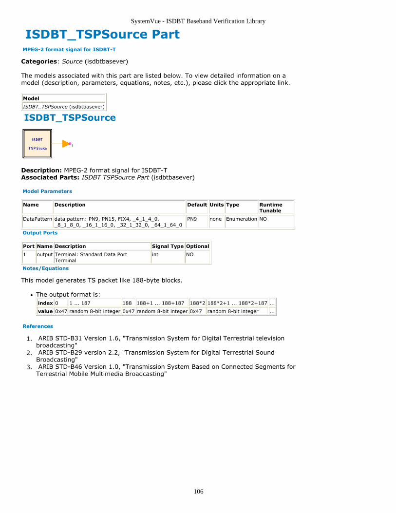
SystemVue - ISDBT Baseband Verification Library
106
ISDBT_TSPSource Part MPEG-2 format signal for ISDBT-T
Categories: Source (isdbtbasever)
The models associated with this part are listed below. To view detailed information on amodel (description, parameters, equations, notes, etc.), please click the appropriate link.
Model
ISDBT_TSPSource (isdbtbasever)
ISDBT_TSPSource
Description: MPEG-2 format signal for ISDBT-TAssociated Parts: ISDBT TSPSource Part (isdbtbasever)
Model Parameters
Name Description Default Units Type RuntimeTunable
DataPattern data pattern: PN9, PN15, FIX4, _4_1_4_0,_8_1_8_0, _16_1_16_0, _32_1_32_0, _64_1_64_0
PN9 none Enumeration NO
Output Ports
Port Name Description Signal Type Optional
1 output Terminal: Standard Data PortTerminal
int NO
Notes/Equations
This model generates TS packet like 188-byte blocks.
The output format is:index 0 1 ... 187 188 188+1 ... 188+187 188*2 188*2+1 ... 188*2+187 ...
value 0x47 random 8-bit integer 0x47 random 8-bit integer 0x47 random 8-bit integer ...
References
ARIB STD-B31 Version 1.6, "Transmission System for Digital Terrestrial television1.broadcasting" ARIB STD-B29 version 2.2, "Transmission System for Digital Terrestrial Sound2.Broadcasting" ARIB STD-B46 Version 1.0, "Transmission System Based on Connected Segments for3.Terrestrial Mobile Multimedia Broadcasting"
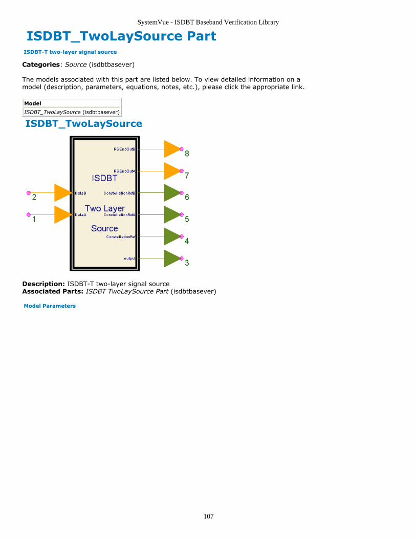
SystemVue - ISDBT Baseband Verification Library
107
ISDBT_TwoLaySource Part ISDBT-T two-layer signal source
Categories: Source (isdbtbasever)
The models associated with this part are listed below. To view detailed information on amodel (description, parameters, equations, notes, etc.), please click the appropriate link.
Model
ISDBT_TwoLaySource (isdbtbasever)
ISDBT_TwoLaySource
Description: ISDBT-T two-layer signal sourceAssociated Parts: ISDBT TwoLaySource Part (isdbtbasever)
Model Parameters
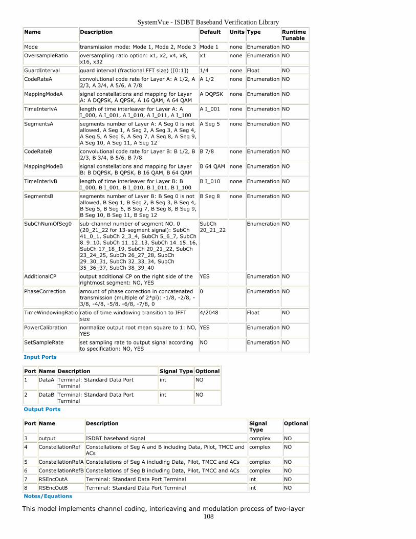
SystemVue - ISDBT Baseband Verification Library
108
Name Description Default Units Type RuntimeTunable
Mode transmission mode: Mode 1, Mode 2, Mode 3 Mode 1 none Enumeration NO
OversampleRatio oversampling ratio option: x1, x2, x4, x8,x16, x32
x1 none Enumeration NO
GuardInterval guard interval (fractional FFT size) ([0:1]) 1/4 none Float NO
CodeRateA convolutional code rate for Layer A: A 1/2, A2/3, A 3/4, A 5/6, A 7/8
A 1/2 none Enumeration NO
MappingModeA signal constellations and mapping for LayerA: A DQPSK, A QPSK, A 16 QAM, A 64 QAM
A DQPSK none Enumeration NO
TimeInterlvA length of time interleaver for Layer A: AI_000, A I_001, A I_010, A I_011, A I_100
A I_001 none Enumeration NO
SegmentsA segments number of Layer A: A Seg 0 is notallowed, A Seg 1, A Seg 2, A Seg 3, A Seg 4,A Seg 5, A Seg 6, A Seg 7, A Seg 8, A Seg 9,A Seg 10, A Seg 11, A Seg 12
A Seg 5 none Enumeration NO
CodeRateB convolutional code rate for Layer B: B 1/2, B2/3, B 3/4, B 5/6, B 7/8
B 7/8 none Enumeration NO
MappingModeB signal constellations and mapping for LayerB: B DQPSK, B QPSK, B 16 QAM, B 64 QAM
B 64 QAM none Enumeration NO
TimeInterlvB length of time interleaver for Layer B: BI_000, B I_001, B I_010, B I_011, B I_100
B I_010 none Enumeration NO
SegmentsB segments number of Layer B: B Seg 0 is notallowed, B Seg 1, B Seg 2, B Seg 3, B Seg 4,B Seg 5, B Seg 6, B Seg 7, B Seg 8, B Seg 9,B Seg 10, B Seg 11, B Seg 12
B Seg 8 none Enumeration NO
SubChNumOfSeg0 sub-channel number of segment NO. 0(20_21_22 for 13-segment signal): SubCh41_0_1, SubCh 2_3_4, SubCh 5_6_7, SubCh8_9_10, SubCh 11_12_13, SubCh 14_15_16,SubCh 17_18_19, SubCh 20_21_22, SubCh23_24_25, SubCh 26_27_28, SubCh29_30_31, SubCh 32_33_34, SubCh35_36_37, SubCh 38_39_40
SubCh20_21_22
Enumeration NO
AdditionalCP output additional CP on the right side of therightmost segment: NO, YES
YES Enumeration NO
PhaseCorrection amount of phase correction in concatenatedtransmission (multiple of 2*pi): -1/8, -2/8, -3/8, -4/8, -5/8, -6/8, -7/8, 0
0 Enumeration NO
TimeWindowingRatio ratio of time windowing transition to IFFTsize
4/2048 Float NO
PowerCalibration normalize output root mean square to 1: NO,YES
YES Enumeration NO
SetSampleRate set sampling rate to output signal accordingto specification: NO, YES
NO Enumeration NO
Input Ports
Port Name Description Signal Type Optional
1 DataA Terminal: Standard Data PortTerminal
int NO
2 DataB Terminal: Standard Data PortTerminal
int NO
Output Ports
Port Name Description SignalType
Optional
3 output ISDBT baseband signal complex NO
4 ConstellationRef Constellations of Seg A and B including Data, Pilot, TMCC andACs
complex NO
5 ConstellationRefA Constellations of Seg A including Data, Pilot, TMCC and ACs complex NO
6 ConstellationRefB Constellations of Seg B including Data, Pilot, TMCC and ACs complex NO
7 RSEncOutA Terminal: Standard Data Port Terminal int NO
8 RSEncOutB Terminal: Standard Data Port Terminal int NO
Notes/Equations
This model implements channel coding, interleaving and modulation process of two-layer
SystemVue - ISDBT Baseband Verification Library
109
ISDB-T baseband transmitter.
FeaturesSegmentsA+SegmentsB must equal to 13.
Parameter detailsSubChNumOfSeg0 specifies the sub-channel number of OFDM segment 0, onlyfor 1-segment and 3-segment transmission. For 13-segment signal, it shouldalways be SubCh_20_21_22. Please refer to Wi PRBS register initial value table(isdbtbasever) for more details.PhaseCompensation must be set to the corresponding value in connectedtransmission according to the phase correction table (isdbtbasever).AdditionalCP should be set to NO in connected transmission when thistransmission layer is not on the rightmost side of the whole transmission band.TimeWindowingRatio is used to add a raised cosine slope to the edges ofeach OFDM symbol so as to reduce out-of-band power leakage. The valueshould generally much smaller than GI ratio (the ratio of guard interval to FFTinterval).PowerCalibration is used to normalize the rms (root mean square) ofbaseband signal to 1.SetSampleRate is used to add sampling rate information to output signal.
I/O detailsDataA and DataB must be 188-byte TS packets in the form of bytes.ConstellationRef, in the OFDM segment sequence of [11,9,...,1,0,2,...,10,12],can be used to measure the RMSE (or EVM) of the modulated signal.ConstellationRefA and ConstellationRefB are in the OFDM segment sequenceof [0,1,2,...,11,12].RSEncOutA and RSEncOutB can be used to measure the BER performance ofViterbi decoding.
References
ARIB STD-B31 Version 1.6, "Transmission System for Digital Terrestrial television1.broadcasting" ARIB STD-B29 version 2.2, "Transmission System for Digital Terrestrial Sound2.Broadcasting" ARIB STD-B46 Version 1.0, "Transmission System Based on Connected Segments for3.Terrestrial Mobile Multimedia Broadcasting"

SystemVue - ISDBT Baseband Verification Library
110
ISDBT TMCC Category Contents
ISDBT EarthquakeAlarm Part (isdbtbasever)ISDBT TMCC Part (isdbtbasever)ISDBT TMCCInfo Part (isdbtbasever)
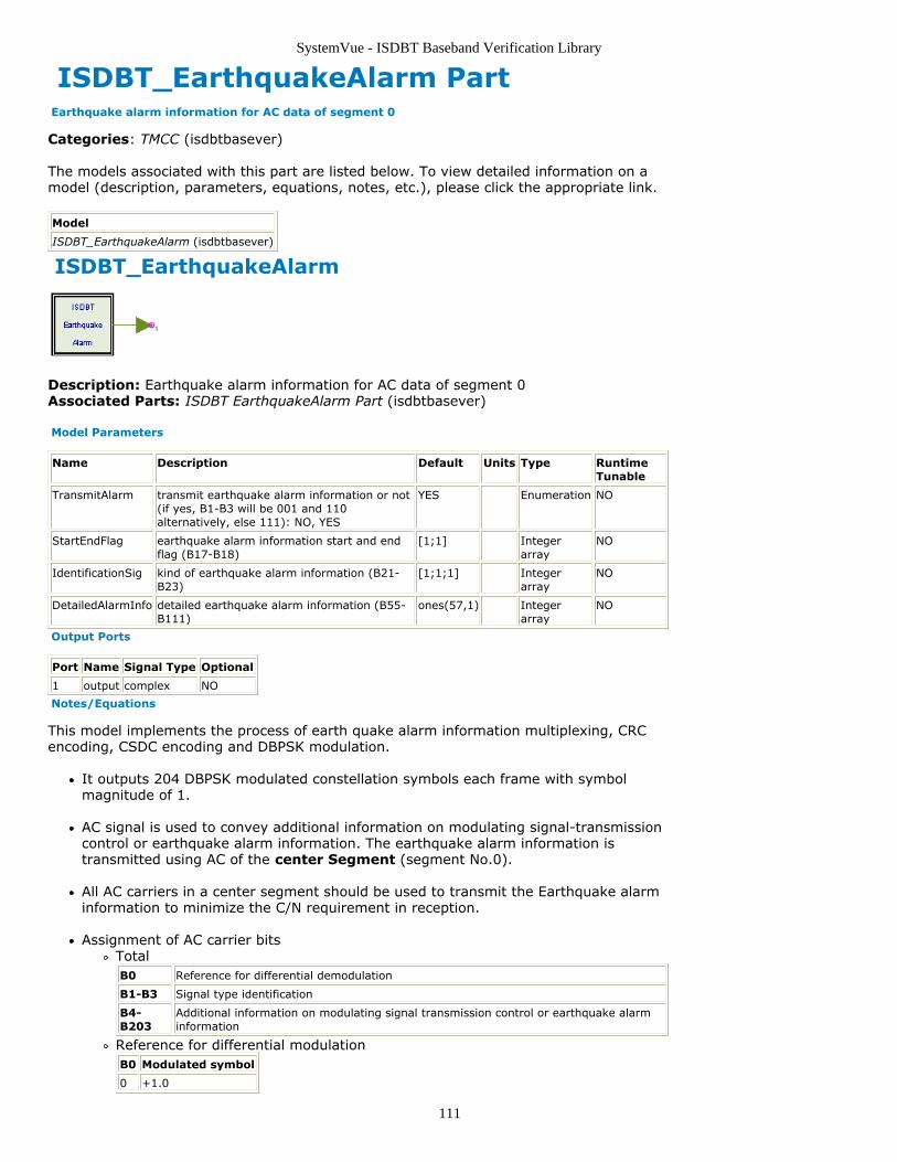
SystemVue - ISDBT Baseband Verification Library
111
ISDBT_EarthquakeAlarm Part Earthquake alarm information for AC data of segment 0
Categories: TMCC (isdbtbasever)
The models associated with this part are listed below. To view detailed information on amodel (description, parameters, equations, notes, etc.), please click the appropriate link.
Model
ISDBT_EarthquakeAlarm (isdbtbasever)
ISDBT_EarthquakeAlarm
Description: Earthquake alarm information for AC data of segment 0Associated Parts: ISDBT EarthquakeAlarm Part (isdbtbasever)
Model Parameters
Name Description Default Units Type RuntimeTunable
TransmitAlarm transmit earthquake alarm information or not(if yes, B1-B3 will be 001 and 110alternatively, else 111): NO, YES
YES Enumeration NO
StartEndFlag earthquake alarm information start and endflag (B17-B18)
[1;1] Integerarray
NO
IdentificationSig kind of earthquake alarm information (B21-B23)
[1;1;1] Integerarray
NO
DetailedAlarmInfo detailed earthquake alarm information (B55-B111)
ones(57,1) Integerarray
NO
Output Ports
Port Name Signal Type Optional
1 output complex NO
Notes/Equations
This model implements the process of earth quake alarm information multiplexing, CRCencoding, CSDC encoding and DBPSK modulation.
It outputs 204 DBPSK modulated constellation symbols each frame with symbolmagnitude of 1.
AC signal is used to convey additional information on modulating signal-transmissioncontrol or earthquake alarm information. The earthquake alarm information istransmitted using AC of the center Segment (segment No.0).
All AC carriers in a center segment should be used to transmit the Earthquake alarminformation to minimize the C/N requirement in reception.
Assignment of AC carrier bitsTotalB0 Reference for differential demodulation
B1-B3 Signal type identification
B4-B203
Additional information on modulating signal transmission control or earthquake alarminformation
Reference for differential modulationB0 Modulated symbol
0 +1.0
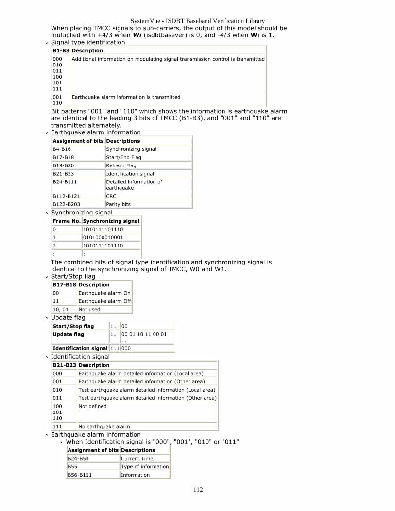
SystemVue - ISDBT Baseband Verification Library
112
When placing TMCC signals to sub-carriers, the output of this model should bemultiplied with +4/3 when Wi (isdbtbasever) is 0, and -4/3 when Wi is 1.Signal type identificationB1-B3 Description
000010011100101111
Additional information on modulating signal transmission control is transmitted
001110
Earthquake alarm information is transmitted
Bit patterns "001" and "110" which shows the information is earthquake alarmare identical to the leading 3 bits of TMCC (B1-B3), and "001" and "110" aretransmitted alternately.Earthquake alarm informationAssignment of bits Descriptions
B4-B16 Synchronizing signal
B17-B18 Start/End Flag
B19-B20 Refresh Flag
B21-B23 Identification signal
B24-B111 Detailed information ofearthquake
B112-B121 CRC
B122-B203 Parity bits
Synchronizing signalFrame No. Synchronizing signal
0 1010111101110
1 0101000010001
2 1010111101110
: :
The combined bits of signal type identification and synchronizing signal isidentical to the synchronizing signal of TMCC, W0 and W1.Start/Stop flagB17-B18 Description
00 Earthquake alarm On
11 Earthquake alarm Off
10, 01 Not used
Update flagStart/Stop flag 11 00
Update flag 11 00 01 10 11 00 01...
Identification signal 111 000
Identification signalB21-B23 Description
000 Earthquake alarm detailed information (Local area)
001 Earthquake alarm detailed information (Other area)
010 Test earthquake alarm detailed information (Local area)
011 Test earthquake alarm detailed information (Other area)
100101110
Not defined
111 No earthquake alarm
Earthquake alarm informationWhen Identification signal is "000", "001", "010" or "011"Assignment of bits Descriptions
B24-B54 Current Time
B55 Type of information
B56-B111 Information
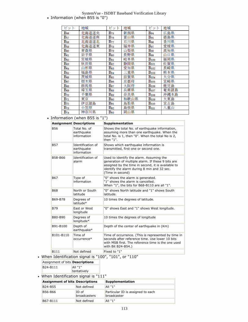
SystemVue - ISDBT Baseband Verification Library
113
Information (when B55 is "0")
Information (when B55 is "1")Assignment Descriptions Supplementation
B56 Total No. ofearthquakeinformation
Shows the total No. of earthquake information,assuming more than one earthquake. When thetotal No. is 1, then "0". When the total No is 2,then "1".
B57 Identification ofearthquakeinformation
Shows which earthquake information istransmitted, first one or second one.
B58-B66 Identification ofalarm
Used to identify the alarm. Assuming thegeneration of multiple alarm. If these 9 bits areassigned by the time in second, it is available toidentify the alarm during 8 min and 32 sec.(Time in second)
B67 Type ofinformation
"0" shows the alarm is generated."1" shows the alarm is cancelled.When "1", the bits for B68-B110 are all "1".
B68 North or Southlatitude
"0" shows North latitude and "1" shows Southlatitude.
B69-B78 Degrees oflatitude*
10 times the degrees of latitude.
B79 East or Westlongitude
"0" shows East and "1" shows West longitude.
B80-B90 Degrees oflongitude*
10 times the degrees of longitude
B91-B100 Depth ofearthquake*
Depth of the center of earthquake in (Km)
B101-B110 Time ofoccurrence*
Time of occurrence. (This is represented by time inseconds after reference time. Use lower 10 bitswith MSB first. The reference time is the one usedwith Bit B24-B54.)
B111 Not defined Fixed to "1"
When Identification signal is "100", "101", or "110"Assignment of bits Descriptions
B24-B111 All "1"tentatively
When Identification signal is "111"Assignment of bits Descriptions Supplementation
B24-B55 Not defined All "1"
B56-B66 ID ofbroadcasters
Particular ID is assigned to eachbroadcaster
B67-B111 Not defined All "1"
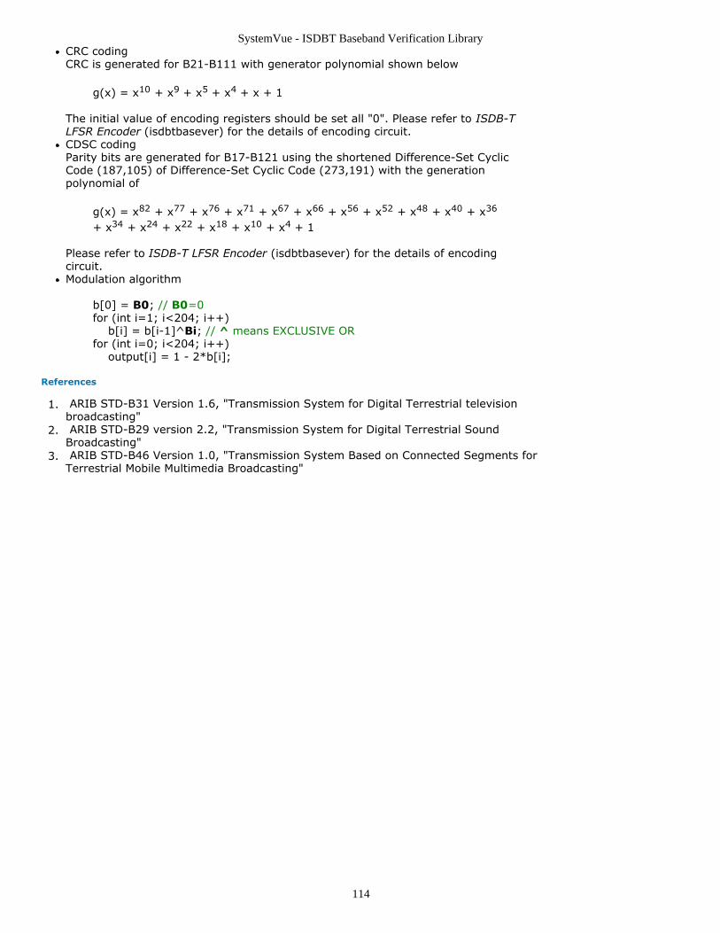
SystemVue - ISDBT Baseband Verification Library
114
CRC codingCRC is generated for B21-B111 with generator polynomial shown below
g(x) = x10 + x9 + x5 + x4 + x + 1
The initial value of encoding registers should be set all "0". Please refer to ISDB-TLFSR Encoder (isdbtbasever) for the details of encoding circuit.CDSC codingParity bits are generated for B17-B121 using the shortened Difference-Set CyclicCode (187,105) of Difference-Set Cyclic Code (273,191) with the generationpolynomial of
g(x) = x82 + x77 + x76 + x71 + x67 + x66 + x56 + x52 + x48 + x40 + x36
+ x34 + x24 + x22 + x18 + x10 + x4 + 1
Please refer to ISDB-T LFSR Encoder (isdbtbasever) for the details of encodingcircuit.Modulation algorithm
b[0] = B0; // B0=0for (int i=1; i<204; i++) b[i] = b[i-1]^Bi; // ^ means EXCLUSIVE ORfor (int i=0; i<204; i++) output[i] = 1 - 2*b[i];
References
ARIB STD-B31 Version 1.6, "Transmission System for Digital Terrestrial television1.broadcasting" ARIB STD-B29 version 2.2, "Transmission System for Digital Terrestrial Sound2.Broadcasting" ARIB STD-B46 Version 1.0, "Transmission System Based on Connected Segments for3.Terrestrial Mobile Multimedia Broadcasting"
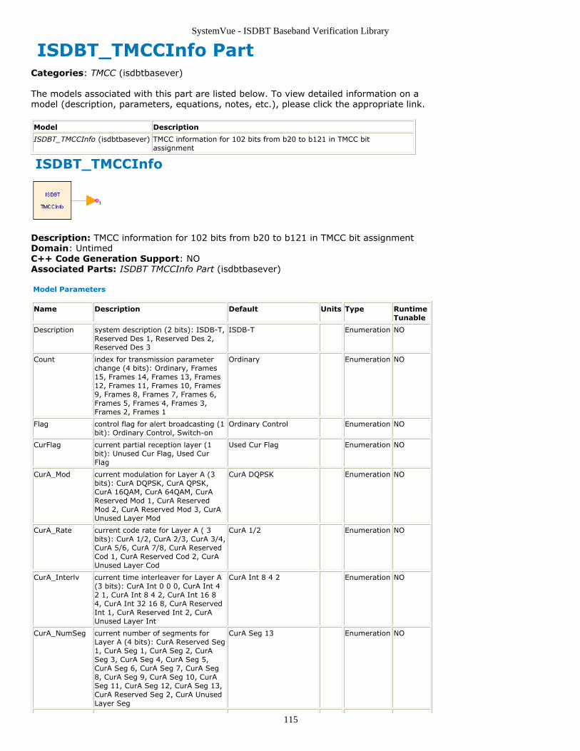
SystemVue - ISDBT Baseband Verification Library
115
ISDBT_TMCCInfo PartCategories: TMCC (isdbtbasever)
The models associated with this part are listed below. To view detailed information on amodel (description, parameters, equations, notes, etc.), please click the appropriate link.
Model Description
ISDBT_TMCCInfo (isdbtbasever) TMCC information for 102 bits from b20 to b121 in TMCC bitassignment
ISDBT_TMCCInfo
Description: TMCC information for 102 bits from b20 to b121 in TMCC bit assignmentDomain: UntimedC++ Code Generation Support: NOAssociated Parts: ISDBT TMCCInfo Part (isdbtbasever)
Model Parameters
Name Description Default Units Type RuntimeTunable
Description system description (2 bits): ISDB-T,Reserved Des 1, Reserved Des 2,Reserved Des 3
ISDB-T Enumeration NO
Count index for transmission parameterchange (4 bits): Ordinary, Frames15, Frames 14, Frames 13, Frames12, Frames 11, Frames 10, Frames9, Frames 8, Frames 7, Frames 6,Frames 5, Frames 4, Frames 3,Frames 2, Frames 1
Ordinary Enumeration NO
Flag control flag for alert broadcasting (1bit): Ordinary Control, Switch-on
Ordinary Control Enumeration NO
CurFlag current partial reception layer (1bit): Unused Cur Flag, Used CurFlag
Used Cur Flag Enumeration NO
CurA_Mod current modulation for Layer A (3bits): CurA DQPSK, CurA QPSK,CurA 16QAM, CurA 64QAM, CurAReserved Mod 1, CurA ReservedMod 2, CurA Reserved Mod 3, CurAUnused Layer Mod
CurA DQPSK Enumeration NO
CurA_Rate current code rate for Layer A ( 3bits): CurA 1/2, CurA 2/3, CurA 3/4,CurA 5/6, CurA 7/8, CurA ReservedCod 1, CurA Reserved Cod 2, CurAUnused Layer Cod
CurA 1/2 Enumeration NO
CurA_Interlv current time interleaver for Layer A(3 bits): CurA Int 0 0 0, CurA Int 42 1, CurA Int 8 4 2, CurA Int 16 84, CurA Int 32 16 8, CurA ReservedInt 1, CurA Reserved Int 2, CurAUnused Layer Int
CurA Int 8 4 2 Enumeration NO
CurA_NumSeg current number of segments forLayer A (4 bits): CurA Reserved Seg1, CurA Seg 1, CurA Seg 2, CurASeg 3, CurA Seg 4, CurA Seg 5,CurA Seg 6, CurA Seg 7, CurA Seg8, CurA Seg 9, CurA Seg 10, CurASeg 11, CurA Seg 12, CurA Seg 13,CurA Reserved Seg 2, CurA UnusedLayer Seg
CurA Seg 13 Enumeration NO
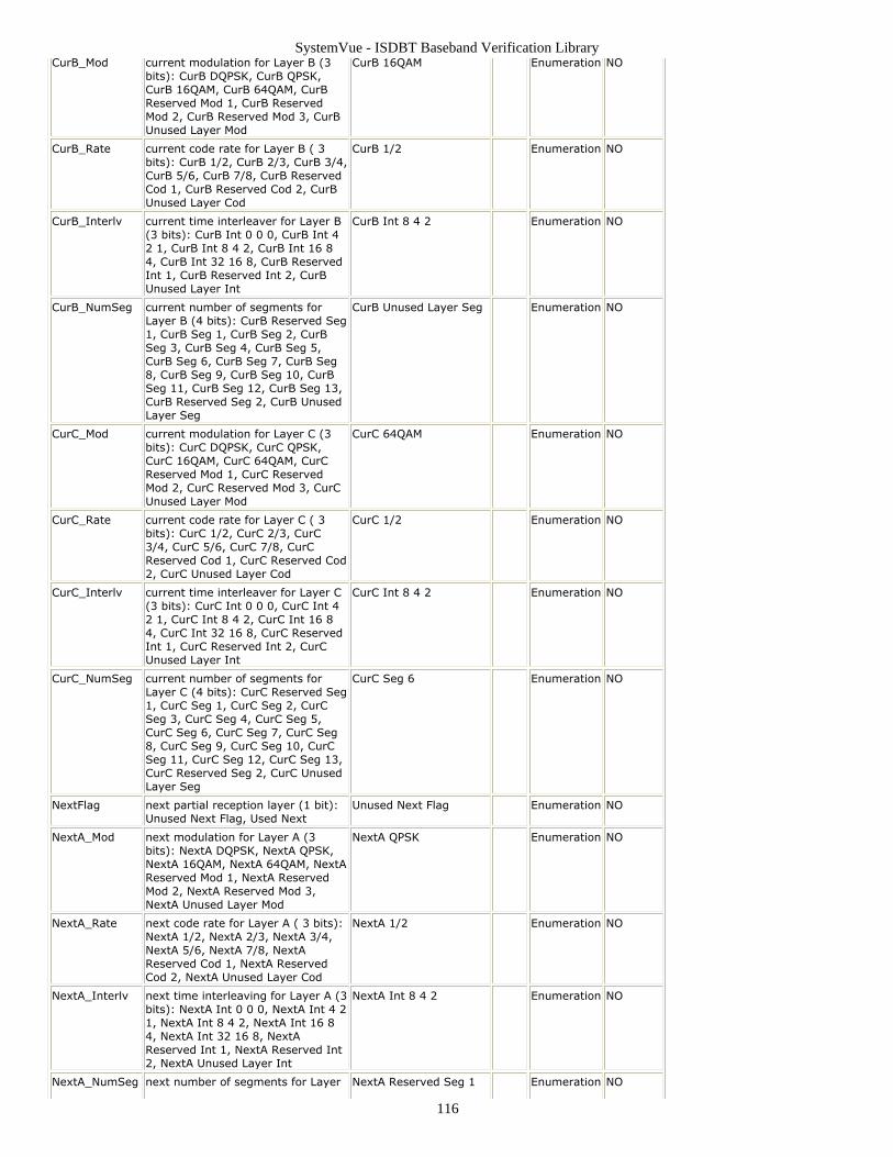
SystemVue - ISDBT Baseband Verification Library
116
CurB_Mod current modulation for Layer B (3bits): CurB DQPSK, CurB QPSK,CurB 16QAM, CurB 64QAM, CurBReserved Mod 1, CurB ReservedMod 2, CurB Reserved Mod 3, CurBUnused Layer Mod
CurB 16QAM Enumeration NO
CurB_Rate current code rate for Layer B ( 3bits): CurB 1/2, CurB 2/3, CurB 3/4,CurB 5/6, CurB 7/8, CurB ReservedCod 1, CurB Reserved Cod 2, CurBUnused Layer Cod
CurB 1/2 Enumeration NO
CurB_Interlv current time interleaver for Layer B(3 bits): CurB Int 0 0 0, CurB Int 42 1, CurB Int 8 4 2, CurB Int 16 84, CurB Int 32 16 8, CurB ReservedInt 1, CurB Reserved Int 2, CurBUnused Layer Int
CurB Int 8 4 2 Enumeration NO
CurB_NumSeg current number of segments forLayer B (4 bits): CurB Reserved Seg1, CurB Seg 1, CurB Seg 2, CurBSeg 3, CurB Seg 4, CurB Seg 5,CurB Seg 6, CurB Seg 7, CurB Seg8, CurB Seg 9, CurB Seg 10, CurBSeg 11, CurB Seg 12, CurB Seg 13,CurB Reserved Seg 2, CurB UnusedLayer Seg
CurB Unused Layer Seg Enumeration NO
CurC_Mod current modulation for Layer C (3bits): CurC DQPSK, CurC QPSK,CurC 16QAM, CurC 64QAM, CurCReserved Mod 1, CurC ReservedMod 2, CurC Reserved Mod 3, CurCUnused Layer Mod
CurC 64QAM Enumeration NO
CurC_Rate current code rate for Layer C ( 3bits): CurC 1/2, CurC 2/3, CurC3/4, CurC 5/6, CurC 7/8, CurCReserved Cod 1, CurC Reserved Cod2, CurC Unused Layer Cod
CurC 1/2 Enumeration NO
CurC_Interlv current time interleaver for Layer C(3 bits): CurC Int 0 0 0, CurC Int 42 1, CurC Int 8 4 2, CurC Int 16 84, CurC Int 32 16 8, CurC ReservedInt 1, CurC Reserved Int 2, CurCUnused Layer Int
CurC Int 8 4 2 Enumeration NO
CurC_NumSeg current number of segments forLayer C (4 bits): CurC Reserved Seg1, CurC Seg 1, CurC Seg 2, CurCSeg 3, CurC Seg 4, CurC Seg 5,CurC Seg 6, CurC Seg 7, CurC Seg8, CurC Seg 9, CurC Seg 10, CurCSeg 11, CurC Seg 12, CurC Seg 13,CurC Reserved Seg 2, CurC UnusedLayer Seg
CurC Seg 6 Enumeration NO
NextFlag next partial reception layer (1 bit):Unused Next Flag, Used Next
Unused Next Flag Enumeration NO
NextA_Mod next modulation for Layer A (3bits): NextA DQPSK, NextA QPSK,NextA 16QAM, NextA 64QAM, NextAReserved Mod 1, NextA ReservedMod 2, NextA Reserved Mod 3,NextA Unused Layer Mod
NextA QPSK Enumeration NO
NextA_Rate next code rate for Layer A ( 3 bits):NextA 1/2, NextA 2/3, NextA 3/4,NextA 5/6, NextA 7/8, NextAReserved Cod 1, NextA ReservedCod 2, NextA Unused Layer Cod
NextA 1/2 Enumeration NO
NextA_Interlv next time interleaving for Layer A (3bits): NextA Int 0 0 0, NextA Int 4 21, NextA Int 8 4 2, NextA Int 16 84, NextA Int 32 16 8, NextAReserved Int 1, NextA Reserved Int2, NextA Unused Layer Int
NextA Int 8 4 2 Enumeration NO
NextA_NumSeg next number of segments for Layer NextA Reserved Seg 1 Enumeration NO
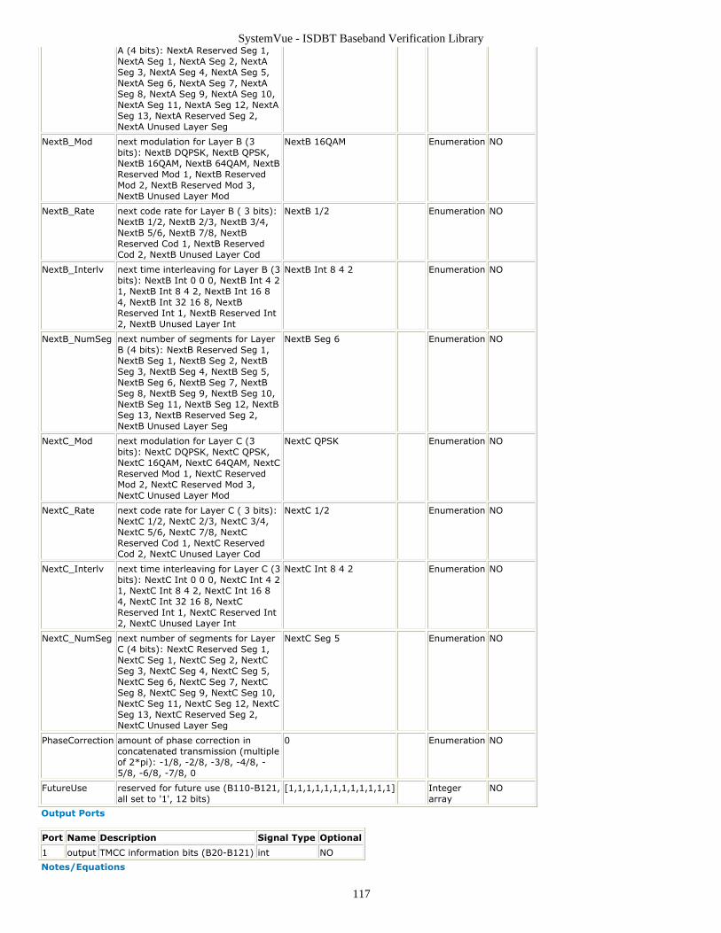
SystemVue - ISDBT Baseband Verification Library
117
A (4 bits): NextA Reserved Seg 1,NextA Seg 1, NextA Seg 2, NextASeg 3, NextA Seg 4, NextA Seg 5,NextA Seg 6, NextA Seg 7, NextASeg 8, NextA Seg 9, NextA Seg 10,NextA Seg 11, NextA Seg 12, NextASeg 13, NextA Reserved Seg 2,NextA Unused Layer Seg
NextB_Mod next modulation for Layer B (3bits): NextB DQPSK, NextB QPSK,NextB 16QAM, NextB 64QAM, NextBReserved Mod 1, NextB ReservedMod 2, NextB Reserved Mod 3,NextB Unused Layer Mod
NextB 16QAM Enumeration NO
NextB_Rate next code rate for Layer B ( 3 bits):NextB 1/2, NextB 2/3, NextB 3/4,NextB 5/6, NextB 7/8, NextBReserved Cod 1, NextB ReservedCod 2, NextB Unused Layer Cod
NextB 1/2 Enumeration NO
NextB_Interlv next time interleaving for Layer B (3bits): NextB Int 0 0 0, NextB Int 4 21, NextB Int 8 4 2, NextB Int 16 84, NextB Int 32 16 8, NextBReserved Int 1, NextB Reserved Int2, NextB Unused Layer Int
NextB Int 8 4 2 Enumeration NO
NextB_NumSeg next number of segments for LayerB (4 bits): NextB Reserved Seg 1,NextB Seg 1, NextB Seg 2, NextBSeg 3, NextB Seg 4, NextB Seg 5,NextB Seg 6, NextB Seg 7, NextBSeg 8, NextB Seg 9, NextB Seg 10,NextB Seg 11, NextB Seg 12, NextBSeg 13, NextB Reserved Seg 2,NextB Unused Layer Seg
NextB Seg 6 Enumeration NO
NextC_Mod next modulation for Layer C (3bits): NextC DQPSK, NextC QPSK,NextC 16QAM, NextC 64QAM, NextCReserved Mod 1, NextC ReservedMod 2, NextC Reserved Mod 3,NextC Unused Layer Mod
NextC QPSK Enumeration NO
NextC_Rate next code rate for Layer C ( 3 bits):NextC 1/2, NextC 2/3, NextC 3/4,NextC 5/6, NextC 7/8, NextCReserved Cod 1, NextC ReservedCod 2, NextC Unused Layer Cod
NextC 1/2 Enumeration NO
NextC_Interlv next time interleaving for Layer C (3bits): NextC Int 0 0 0, NextC Int 4 21, NextC Int 8 4 2, NextC Int 16 84, NextC Int 32 16 8, NextCReserved Int 1, NextC Reserved Int2, NextC Unused Layer Int
NextC Int 8 4 2 Enumeration NO
NextC_NumSeg next number of segments for LayerC (4 bits): NextC Reserved Seg 1,NextC Seg 1, NextC Seg 2, NextCSeg 3, NextC Seg 4, NextC Seg 5,NextC Seg 6, NextC Seg 7, NextCSeg 8, NextC Seg 9, NextC Seg 10,NextC Seg 11, NextC Seg 12, NextCSeg 13, NextC Reserved Seg 2,NextC Unused Layer Seg
NextC Seg 5 Enumeration NO
PhaseCorrection amount of phase correction inconcatenated transmission (multipleof 2*pi): -1/8, -2/8, -3/8, -4/8, -5/8, -6/8, -7/8, 0
0 Enumeration NO
FutureUse reserved for future use (B110-B121,all set to '1', 12 bits)
[1,1,1,1,1,1,1,1,1,1,1,1] Integerarray
NO
Output Ports
Port Name Description Signal Type Optional
1 output TMCC information bits (B20-B121) int NO
Notes/Equations
SystemVue - ISDBT Baseband Verification Library
118
This model mapps the transmission multiplexing configuration control (TMCC) informationto the TMCC bits of b20 to b121 according to ISDBT TMCC Information (isdbtbasever).
References
ARIB STD-B31 Version 1.6, "Transmission System for Digital Terrestrial television1.broadcasting" ARIB STD-B29 version 2.2, "Transmission System for Digital Terrestrial Sound2.Broadcasting" ARIB STD-B46 Version 1.0, "Transmission System Based on Connected Segments for3.Terrestrial Mobile Multimedia Broadcasting"
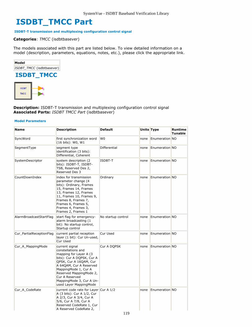
SystemVue - ISDBT Baseband Verification Library
119
ISDBT_TMCC Part ISDBT-T transmission and multiplexing configuration control signal
Categories: TMCC (isdbtbasever)
The models associated with this part are listed below. To view detailed information on amodel (description, parameters, equations, notes, etc.), please click the appropriate link.
Model
ISDBT_TMCC (isdbtbasever)
ISDBT_TMCC
Description: ISDBT-T transmission and multiplexing configuration control signalAssociated Parts: ISDBT TMCC Part (isdbtbasever)
Model Parameters
Name Description Default Units Type RuntimeTunable
SyncWord first synchronization word(16 bits): W0, W1
W0 none Enumeration NO
SegmentType segment typeidentification (3 bits):Differential, Coherent
Differential none Enumeration NO
SystemDescriptor system description (2bits): ISDBT-T, ISDBT-TSB, Reserved Des 2,Reserved Des 3
ISDBT-T none Enumeration NO
CountDownIndex index for transmissionparameter change (4bits): Ordinary, Frames15, Frames 14, Frames13, Frames 12, Frames11, Frames 10, Frames 9,Frames 8, Frames 7,Frames 6, Frames 5,Frames 4, Frames 3,Frames 2, Frames 1
Ordinary none Enumeration NO
AlarmBroadcastStartFlag start flag for emergency-alarm broadcasting (1bit): No startup control,Startup control
No startup control none Enumeration NO
Cur_PartialReceptionFlag current partial receptionlayer (1 bit): Cur Un-used,Cur Used
Cur Used none Enumeration NO
Cur_A_MappingMode current signalconstellations andmapping for Layer A (3bits): Cur A DQPSK, Cur AQPSK, Cur A 16QAM, CurA 64QAM, Cur A ReservedMappingMode 1, Cur AReserved MappingMode 2,Cur A ReservedMappingMode 3, Cur A Un-used Layer MappingMode
Cur A DQPSK none Enumeration NO
Cur_A_CodeRate current code rate for LayerA (3 bits): Cur A 1/2, CurA 2/3, Cur A 3/4, Cur A5/6, Cur A 7/8, Cur AReserved CodeRate 1, CurA Reserved CodeRate 2,
Cur A 1/2 none Enumeration NO
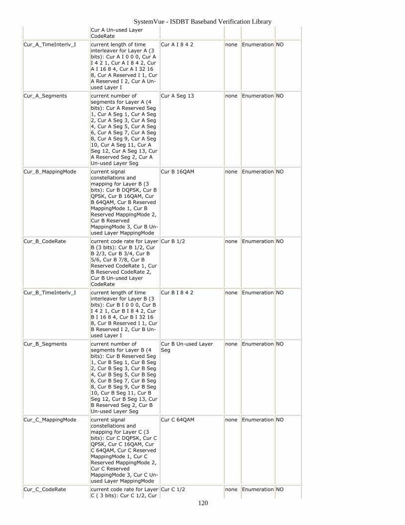
SystemVue - ISDBT Baseband Verification Library
120
Cur A Un-used LayerCodeRate
Cur_A_TimeInterlv_I current length of timeinterleaver for Layer A (3bits): Cur A I 0 0 0, Cur AI 4 2 1, Cur A I 8 4 2, CurA I 16 8 4, Cur A I 32 168, Cur A Reserved I 1, CurA Reserved I 2, Cur A Un-used Layer I
Cur A I 8 4 2 none Enumeration NO
Cur_A_Segments current number ofsegments for Layer A (4bits): Cur A Reserved Seg1, Cur A Seg 1, Cur A Seg2, Cur A Seg 3, Cur A Seg4, Cur A Seg 5, Cur A Seg6, Cur A Seg 7, Cur A Seg8, Cur A Seg 9, Cur A Seg10, Cur A Seg 11, Cur ASeg 12, Cur A Seg 13, CurA Reserved Seg 2, Cur AUn-used Layer Seg
Cur A Seg 13 none Enumeration NO
Cur_B_MappingMode current signalconstellations andmapping for Layer B (3bits): Cur B DQPSK, Cur BQPSK, Cur B 16QAM, CurB 64QAM, Cur B ReservedMappingMode 1, Cur BReserved MappingMode 2,Cur B ReservedMappingMode 3, Cur B Un-used Layer MappingMode
Cur B 16QAM none Enumeration NO
Cur_B_CodeRate current code rate for LayerB (3 bits): Cur B 1/2, CurB 2/3, Cur B 3/4, Cur B5/6, Cur B 7/8, Cur BReserved CodeRate 1, CurB Reserved CodeRate 2,Cur B Un-used LayerCodeRate
Cur B 1/2 none Enumeration NO
Cur_B_TimeInterlv_I current length of timeinterleaver for Layer B (3bits): Cur B I 0 0 0, Cur BI 4 2 1, Cur B I 8 4 2, CurB I 16 8 4, Cur B I 32 168, Cur B Reserved I 1, CurB Reserved I 2, Cur B Un-used Layer I
Cur B I 8 4 2 none Enumeration NO
Cur_B_Segments current number ofsegments for Layer B (4bits): Cur B Reserved Seg1, Cur B Seg 1, Cur B Seg2, Cur B Seg 3, Cur B Seg4, Cur B Seg 5, Cur B Seg6, Cur B Seg 7, Cur B Seg8, Cur B Seg 9, Cur B Seg10, Cur B Seg 11, Cur BSeg 12, Cur B Seg 13, CurB Reserved Seg 2, Cur BUn-used Layer Seg
Cur B Un-used LayerSeg
none Enumeration NO
Cur_C_MappingMode current signalconstellations andmapping for Layer C (3bits): Cur C DQPSK, Cur CQPSK, Cur C 16QAM, CurC 64QAM, Cur C ReservedMappingMode 1, Cur CReserved MappingMode 2,Cur C ReservedMappingMode 3, Cur C Un-used Layer MappingMode
Cur C 64QAM none Enumeration NO
Cur_C_CodeRate current code rate for LayerC ( 3 bits): Cur C 1/2, Cur
Cur C 1/2 none Enumeration NO
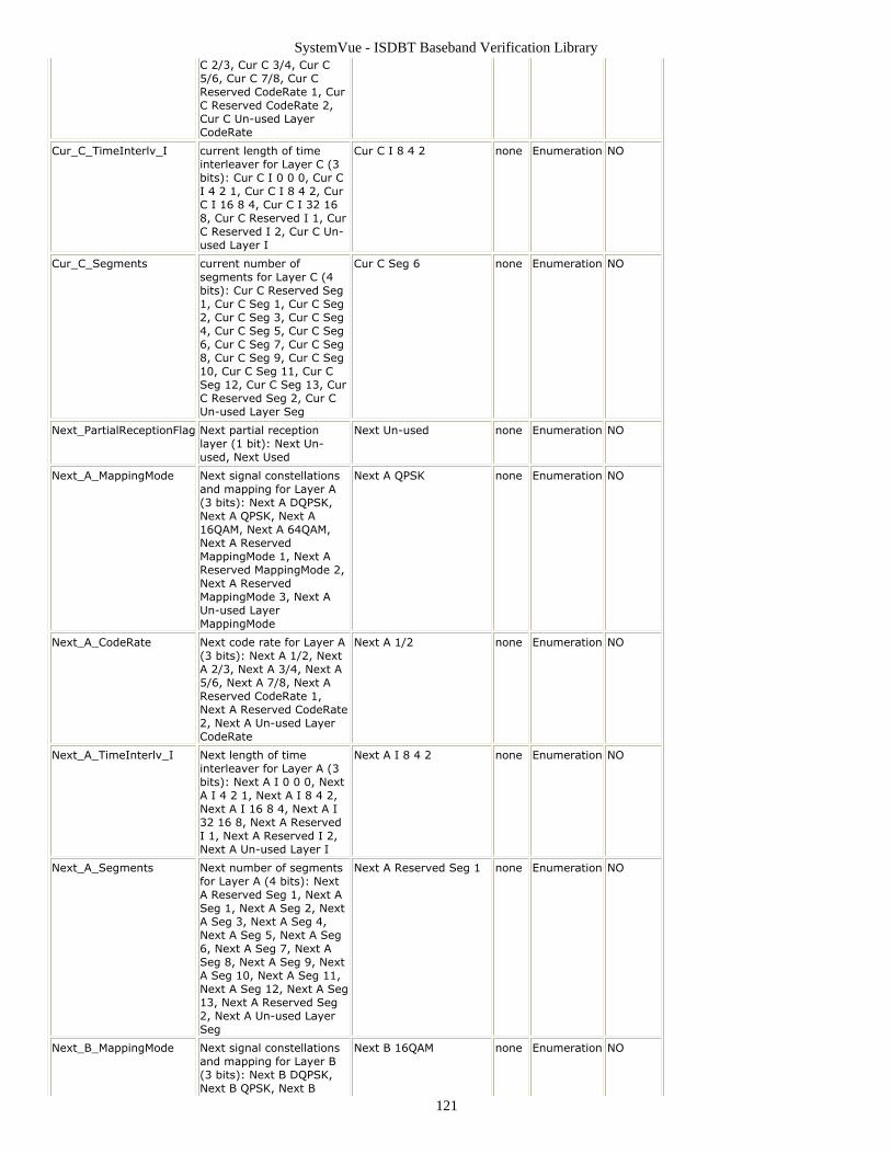
SystemVue - ISDBT Baseband Verification Library
121
C 2/3, Cur C 3/4, Cur C5/6, Cur C 7/8, Cur CReserved CodeRate 1, CurC Reserved CodeRate 2,Cur C Un-used LayerCodeRate
Cur_C_TimeInterlv_I current length of timeinterleaver for Layer C (3bits): Cur C I 0 0 0, Cur CI 4 2 1, Cur C I 8 4 2, CurC I 16 8 4, Cur C I 32 168, Cur C Reserved I 1, CurC Reserved I 2, Cur C Un-used Layer I
Cur C I 8 4 2 none Enumeration NO
Cur_C_Segments current number ofsegments for Layer C (4bits): Cur C Reserved Seg1, Cur C Seg 1, Cur C Seg2, Cur C Seg 3, Cur C Seg4, Cur C Seg 5, Cur C Seg6, Cur C Seg 7, Cur C Seg8, Cur C Seg 9, Cur C Seg10, Cur C Seg 11, Cur CSeg 12, Cur C Seg 13, CurC Reserved Seg 2, Cur CUn-used Layer Seg
Cur C Seg 6 none Enumeration NO
Next_PartialReceptionFlag Next partial receptionlayer (1 bit): Next Un-used, Next Used
Next Un-used none Enumeration NO
Next_A_MappingMode Next signal constellationsand mapping for Layer A(3 bits): Next A DQPSK,Next A QPSK, Next A16QAM, Next A 64QAM,Next A ReservedMappingMode 1, Next AReserved MappingMode 2,Next A ReservedMappingMode 3, Next AUn-used LayerMappingMode
Next A QPSK none Enumeration NO
Next_A_CodeRate Next code rate for Layer A(3 bits): Next A 1/2, NextA 2/3, Next A 3/4, Next A5/6, Next A 7/8, Next AReserved CodeRate 1,Next A Reserved CodeRate2, Next A Un-used LayerCodeRate
Next A 1/2 none Enumeration NO
Next_A_TimeInterlv_I Next length of timeinterleaver for Layer A (3bits): Next A I 0 0 0, NextA I 4 2 1, Next A I 8 4 2,Next A I 16 8 4, Next A I32 16 8, Next A ReservedI 1, Next A Reserved I 2,Next A Un-used Layer I
Next A I 8 4 2 none Enumeration NO
Next_A_Segments Next number of segmentsfor Layer A (4 bits): NextA Reserved Seg 1, Next ASeg 1, Next A Seg 2, NextA Seg 3, Next A Seg 4,Next A Seg 5, Next A Seg6, Next A Seg 7, Next ASeg 8, Next A Seg 9, NextA Seg 10, Next A Seg 11,Next A Seg 12, Next A Seg13, Next A Reserved Seg2, Next A Un-used LayerSeg
Next A Reserved Seg 1 none Enumeration NO
Next_B_MappingMode Next signal constellationsand mapping for Layer B(3 bits): Next B DQPSK,Next B QPSK, Next B
Next B 16QAM none Enumeration NO
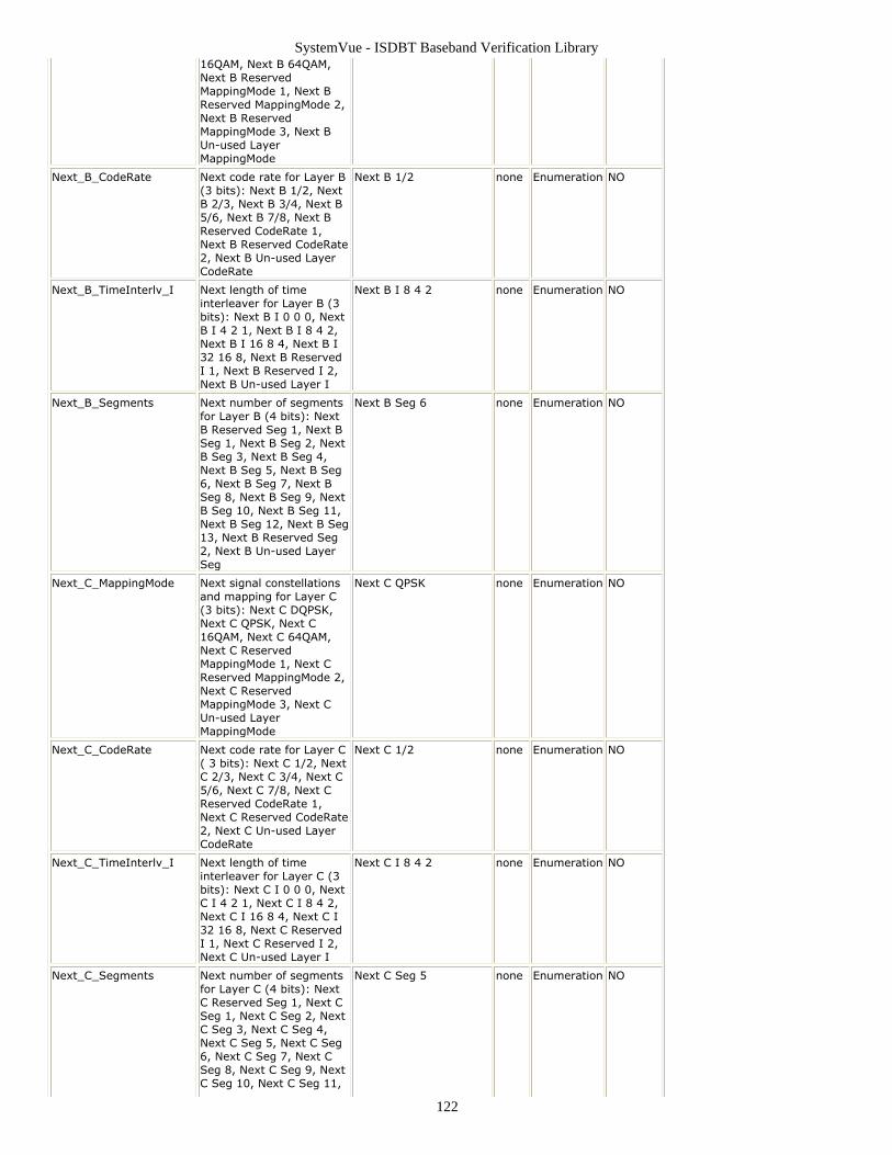
SystemVue - ISDBT Baseband Verification Library
122
16QAM, Next B 64QAM,Next B ReservedMappingMode 1, Next BReserved MappingMode 2,Next B ReservedMappingMode 3, Next BUn-used LayerMappingMode
Next_B_CodeRate Next code rate for Layer B(3 bits): Next B 1/2, NextB 2/3, Next B 3/4, Next B5/6, Next B 7/8, Next BReserved CodeRate 1,Next B Reserved CodeRate2, Next B Un-used LayerCodeRate
Next B 1/2 none Enumeration NO
Next_B_TimeInterlv_I Next length of timeinterleaver for Layer B (3bits): Next B I 0 0 0, NextB I 4 2 1, Next B I 8 4 2,Next B I 16 8 4, Next B I32 16 8, Next B ReservedI 1, Next B Reserved I 2,Next B Un-used Layer I
Next B I 8 4 2 none Enumeration NO
Next_B_Segments Next number of segmentsfor Layer B (4 bits): NextB Reserved Seg 1, Next BSeg 1, Next B Seg 2, NextB Seg 3, Next B Seg 4,Next B Seg 5, Next B Seg6, Next B Seg 7, Next BSeg 8, Next B Seg 9, NextB Seg 10, Next B Seg 11,Next B Seg 12, Next B Seg13, Next B Reserved Seg2, Next B Un-used LayerSeg
Next B Seg 6 none Enumeration NO
Next_C_MappingMode Next signal constellationsand mapping for Layer C(3 bits): Next C DQPSK,Next C QPSK, Next C16QAM, Next C 64QAM,Next C ReservedMappingMode 1, Next CReserved MappingMode 2,Next C ReservedMappingMode 3, Next CUn-used LayerMappingMode
Next C QPSK none Enumeration NO
Next_C_CodeRate Next code rate for Layer C( 3 bits): Next C 1/2, NextC 2/3, Next C 3/4, Next C5/6, Next C 7/8, Next CReserved CodeRate 1,Next C Reserved CodeRate2, Next C Un-used LayerCodeRate
Next C 1/2 none Enumeration NO
Next_C_TimeInterlv_I Next length of timeinterleaver for Layer C (3bits): Next C I 0 0 0, NextC I 4 2 1, Next C I 8 4 2,Next C I 16 8 4, Next C I32 16 8, Next C ReservedI 1, Next C Reserved I 2,Next C Un-used Layer I
Next C I 8 4 2 none Enumeration NO
Next_C_Segments Next number of segmentsfor Layer C (4 bits): NextC Reserved Seg 1, Next CSeg 1, Next C Seg 2, NextC Seg 3, Next C Seg 4,Next C Seg 5, Next C Seg6, Next C Seg 7, Next CSeg 8, Next C Seg 9, NextC Seg 10, Next C Seg 11,
Next C Seg 5 none Enumeration NO
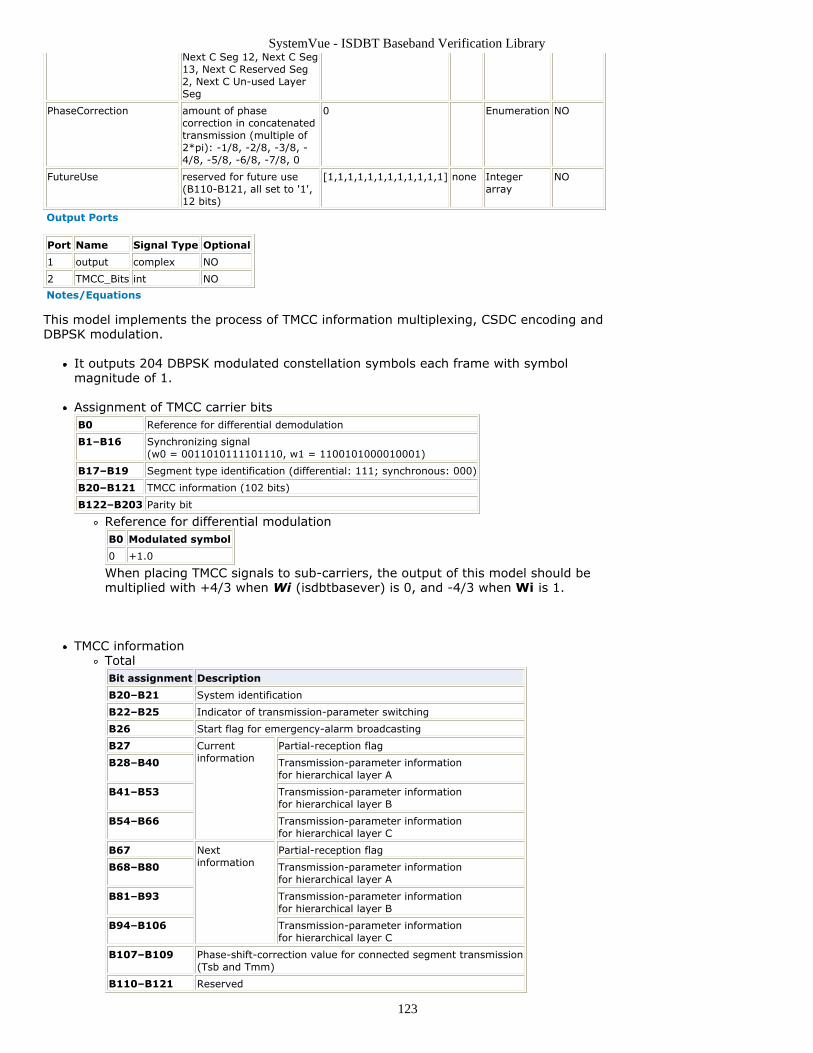
SystemVue - ISDBT Baseband Verification Library
123
Next C Seg 12, Next C Seg13, Next C Reserved Seg2, Next C Un-used LayerSeg
PhaseCorrection amount of phasecorrection in concatenatedtransmission (multiple of2*pi): -1/8, -2/8, -3/8, -4/8, -5/8, -6/8, -7/8, 0
0 Enumeration NO
FutureUse reserved for future use(B110-B121, all set to '1',12 bits)
[1,1,1,1,1,1,1,1,1,1,1,1] none Integerarray
NO
Output Ports
Port Name Signal Type Optional
1 output complex NO
2 TMCC_Bits int NO
Notes/Equations
This model implements the process of TMCC information multiplexing, CSDC encoding andDBPSK modulation.
It outputs 204 DBPSK modulated constellation symbols each frame with symbolmagnitude of 1.
Assignment of TMCC carrier bitsB0 Reference for differential demodulation
B1–B16 Synchronizing signal(w0 = 0011010111101110, w1 = 1100101000010001)
B17–B19 Segment type identification (differential: 111; synchronous: 000)
B20–B121 TMCC information (102 bits)
B122–B203 Parity bit
Reference for differential modulationB0 Modulated symbol
0 +1.0
When placing TMCC signals to sub-carriers, the output of this model should bemultiplied with +4/3 when Wi (isdbtbasever) is 0, and -4/3 when Wi is 1.
TMCC informationTotalBit assignment Description
B20–B21 System identification
B22–B25 Indicator of transmission-parameter switching
B26 Start flag for emergency-alarm broadcasting
B27 Currentinformation
Partial-reception flag
B28–B40 Transmission-parameter informationfor hierarchical layer A
B41–B53 Transmission-parameter informationfor hierarchical layer B
B54–B66 Transmission-parameter informationfor hierarchical layer C
B67 Nextinformation
Partial-reception flag
B68–B80 Transmission-parameter informationfor hierarchical layer A
B81–B93 Transmission-parameter informationfor hierarchical layer B
B94–B106 Transmission-parameter informationfor hierarchical layer C
B107–B109 Phase-shift-correction value for connected segment transmission(Tsb and Tmm)
B110–B121 Reserved
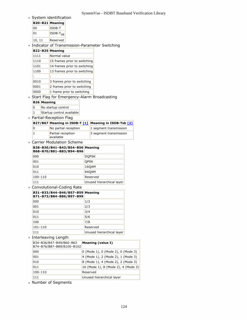
SystemVue - ISDBT Baseband Verification Library
124
System identificationB20–B21 Meaning
00 ISDB-T
01 ISDB-TSB
10, 11 Reserved
Indicator of Transmission-Parameter SwitchingB22–B25 Meaning
1111 Normal value
1110 15 frames prior to switching
1101 14 frames prior to switching
1100 13 frames prior to switching
: :
0010 3 frames prior to switching
0001 2 frames prior to switching
0000 1 frame prior to switching
Start Flag for Emergency-Alarm BroadcastingB26 Meaning
0 No startup control
1 Startup control available
Partial-Reception FlagB27/B67 Meaning in ISDB-T [1] Meaning in ISDB-Tsb [2]
0 No partial reception 1 segment transmission
1 Partial receptionavailable
3 segment transmission
Carrier Modulation SchemeB28–B30/B41–B43/B54–B56B68–B70/B81–B83/B94–B96
Meaning
000 DQPSK
001 QPSK
010 16QAM
011 64QAM
100–110 Reserved
111 Unused hierarchical layer
Convolutional-Coding RateB31–B33/B44–B46/B57–B59B71–B73/B84–B86/B97–B99
Meaning
000 1/2
001 2/3
010 3/4
011 5/6
100 7/8
101–110 Reserved
111 Unused hierarchical layer
Interleaving LengthB34–B36/B47–B49/B60–B62B74–B76/B87–B89/B100–B102
Meaning (value I)
000 0 (Mode 1), 0 (Mode 2), 0 (Mode 3)
001 4 (Mode 1), 2 (Mode 2), 1 (Mode 3)
010 8 (Mode 1), 4 (Mode 2), 2 (Mode 3)
011 16 (Mode 1), 8 (Mode 2), 4 (Mode 3)
100–110 Reserved
111 Unused hierarchical layer
Number of Segments
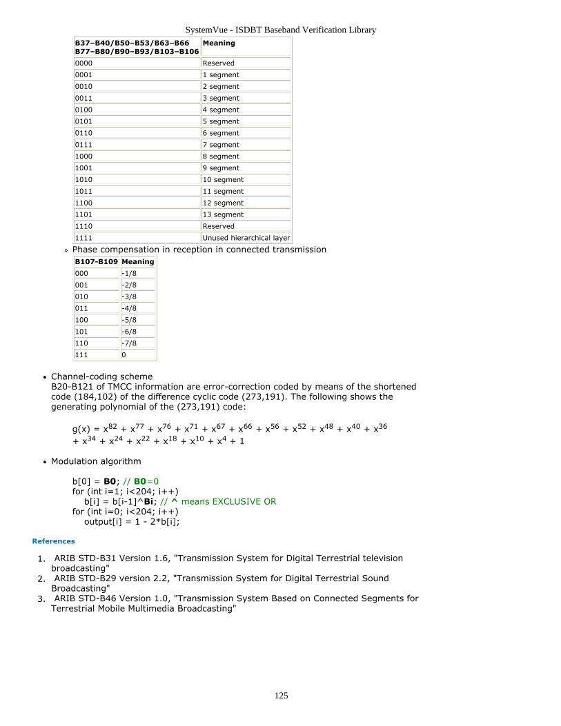
SystemVue - ISDBT Baseband Verification Library
125
B37–B40/B50–B53/B63–B66B77–B80/B90–B93/B103–B106
Meaning
0000 Reserved
0001 1 segment
0010 2 segment
0011 3 segment
0100 4 segment
0101 5 segment
0110 6 segment
0111 7 segment
1000 8 segment
1001 9 segment
1010 10 segment
1011 11 segment
1100 12 segment
1101 13 segment
1110 Reserved
1111 Unused hierarchical layer
Phase compensation in reception in connected transmissionB107-B109 Meaning
000 -1/8
001 -2/8
010 -3/8
011 -4/8
100 -5/8
101 -6/8
110 -7/8
111 0
Channel-coding schemeB20-B121 of TMCC information are error-correction coded by means of the shortenedcode (184,102) of the difference cyclic code (273,191). The following shows thegenerating polynomial of the (273,191) code:
g(x) = x82 + x77 + x76 + x71 + x67 + x66 + x56 + x52 + x48 + x40 + x36
+ x34 + x24 + x22 + x18 + x10 + x4 + 1
Modulation algorithm
b[0] = B0; // B0=0for (int i=1; i<204; i++) b[i] = b[i-1]^Bi; // ^ means EXCLUSIVE ORfor (int i=0; i<204; i++) output[i] = 1 - 2*b[i];
References
ARIB STD-B31 Version 1.6, "Transmission System for Digital Terrestrial television1.broadcasting" ARIB STD-B29 version 2.2, "Transmission System for Digital Terrestrial Sound2.Broadcasting" ARIB STD-B46 Version 1.0, "Transmission System Based on Connected Segments for3.Terrestrial Mobile Multimedia Broadcasting"