water wave pressures on seawalls and breakwaters
TRANSCRIPT

< « /RESEARCH REPORT NO. 2-10
WATER WAVE PRESSURES ON SEAWALLS AND BREAKWATERS
by
-r A . M. Kamel
IDSL
i d i Eu ur
M p¡01
j
i i o i
February 1968
Sponsored by
Office, Chief of Engineers
U. S. Army
Conducted by
T A7.W34rr2-101968
U. S. Army Engineer Waterways Experiment Station
CO RPS O F EN G IN EER SVicksburg, Mississippi
THIS DOCUMENT HAS BEEN APPROVED FOR PUBLIC RELEASE AND SALE; ITS DISTRIBUTION IS UNLIMITED

e /
LIBRARY
A P R 1 7 1968
Bureau of Reclamation Denver, Colorado
Destroy this repo
The find ings in th is report are not to be construed as an o ff ic ia l Department of the Army position , un less so
designated by other authorized documents.

BUREAU OF RECLAMATION nFNYEfi LIBRARY/ I
92067297
7RESEARCH REPORT NO. 2-10
WATER WAVE PRESSURES ON SEAWALLS AND BREAKWATERS
by
A. M. Kamel
IDIi_r
IDI<?=> IDI
IDffiDOIDI
February I960
Sponsored by
Office, Chief of Engineers U. S. Army
Conducted by
Army Engineer Waterways Experiment Station/ C O R P S O F E N G IN E E R S
Vicksburg, MississippiA R M Y - M R C V I C K S B U R G . M I S S .
THIS DOCUMENT HAS BEEN APPROVED FOR PUBLIC RELEASE AND SALE; ITS DISTRIBUTION IS UNLIMITED
92067297

IN R E P L Y R E F E R TO«
DEPARTMENT OF THE ARMYW A T E R W A Y S E X P E R IM E N T S T A T IO N . C O R P S O F E N G IN E E R S
P. O . B O X 6 3 1
V IC K S B U R G , M IS S IS S IP P I 3 9 1 8 0
Errata Sheet
No. 2
23 April 1971
WATER WAVE PRESSURES ON SEAWALLS AND BREAKWATERSResearch Report No._ 2-10
February ±968
Page vii, second line from bottom should read:k Shoaling coefficient; k = h/h 's b
A 2. Page 13, last line of equation b should read:sin 2mxo|
+ (1 - X2) X | sin 2kt 2 -><L sinh md)
- 3. page 15 , last three lines of equation 10 should read:+ (l - X2) sin 2kt sin 2mx|
3B1H2 cosh 2m(d * y) ffi +— -1 f O L V /
LO sinh0 md cosh mdXmH2+ (l - X2) sin 2kt sin 2mx] + ~ — tanh md cos 2kt
1 1. Page l6, last line of equation 12 should read:
cos 2kt cos 2mx
( b )
+ 6(1 - X2) sin 2kt sin 2mx 2sinh md ' cosh md
5. Page l8, last two columns of tabulation should read.
cosh my 2 cosh m(d + y )
(10)
(12)
Wave Pressure, Feet of WaterUnder Under
Wave Crest Wave Trough33- 531.9^
16.1+6 13.^0

FOREWORD
Authority for the U. S. Army Engineer Waterways Experiment Station to conduct Engineering Study No. 813, "Wave Force on Breakwaters," was contained in letters from the Office, Chief of Engineers, dated 1 December 19^7 and it September l$>t8; however, the investigation was not begun until 27 June 1963 because of a shortage in personnel.
Liaison with the Office, Chief of Engineers, has been maintained throughout the course of the investigation by means of progress reports and conferences. Mr. C. E. Lee, Assistant Chief, Hydraulic Design Branch, Engineering Division, Civil Works, Office, Chief of Engineers, has visited the Waterways Experiment Station at various times in connection with the study.
The investigation was conducted in the Hydraulics Division of the Waterways Experiment Station under the direction of Mr. E. P. Fortson, Jr., Chief of the Hydraulics Division, and Mr. R. Y. Hudson, Chief of the Water Waves Branch. The investigation was conducted by Dr. A. M. Kamel, Chief of the Wave Dynamics Section. This report, prepared by Dr. Kamel, is the first in a series of reports on wave forces on breakwaters.
Director of the Waterways Experiment Station during the conduct of this study and preparation and publication of this report was COL John R. Oswalt, Jr., CE. Technical Director was Mr. J. B. Tiffany.
iii


CONTENTSPage
FOREWORD............................................................ iiiNOTATION............................................................ viiCONVERSION FACTORS, BRITISH TO METRIC UNITS OF MEASUREMENT ........ xiS U M M A R Y ............................................................ xiiiPART I: INTRODUCTION.............................................. 1
Background..................................................... 1Purpose and Scope of Study ................................... 2
PART II: SELECTION OF THE DESIGN W A V E ............................. k
Nonbreaking Waves Reflected by the Structure ................. kWaves Breaking on the S t r u c t u r e ............................. 5
PART III: WAVE REFLECTION COEFFICIENTS OF STRUCTURES............ 9PART IV: PRESSURES ON SEAWALLS AND BREAKWATERS CAUSED BYNONBREAKING WAVES REFLECTED BY THE STRUCTURE..................... 13
Mean Level of a Reflected Wave Above Still-Water Level . . . . 13Equations of Wave Pressure................................... IkE x a m p l e ...................................................... 17
PART V: PRESSURES ON SEAWALLS AND BREAKWATERS CAUSED BY WAVESBREAKING ON THE STR U C T U R E ....................................... 19
Minikinf s F o r m u l a ............................................ 20The Waterways Experiment Station Formula..................... 22Experimental Verification of the Waterways Experiment Station
F o r m u l a .................................................... 28E x a m p l e ...................................................... 3 -
PART VI: CONCLUSION................................................ 36LITERATURE C I T E D .................................................... 38
v


NOTATION
(t),a1(t) Positions of the moving particles that form the ends of a column of fluid
CA
CBd
Acoustic velocity in water
Acoustic velocity in structure
Water depth
dwD
Water depth at toe of structure
Thickness of entrapped layer of air, equation 21; also water depth in deeper water, one wavelength seaward of structure, equations 23 and 26
Eo/(t)
Deepwater wave energy
A function of t
F Fetch length, nautical miles
F*2 A harmonic function of x and y that is periodic with respect to time
g Acceleration due to gravity
H Wave height at depth d ; also height wave would have at local depth if it was not altered by reflected wave
«B
( V o
Height of wave just breaking on structure
Significant wave height in deep water, ft; i.e. the average of the one-third highest in a given train of waves
H.1Hmax
Ho
j
Incident wave height
Maximum wave height for given condition
Wave height in deep water
Reflected wave height
Integral
k 2jt/ t
k
« 1 ^
Shoaling coefficient; kg = E /h
Constants
vii

L Wavelength at depth d Wavelength at depth D
Lq Wavelength in deep water m 2 jt/ l
p Pressure; also wave pressurep Maximum dynamic pressure (also shock pressure) caused by waves
breaking on structurep^ Atmospheric pressure; also pressure at location o p^ Theoretical shock pressure behind shock front P Total momentum flux t Time; also wind duration T Wave period
Tp Significant wave period, secU jV jW Particle velocity in x , y , and z directions, respectively
u^ Velocity of liquid ahead of shock front in liquid; also impact velocity with which wave strikes structure
u^ Velocity of plane of impact between water and structureU Wind speed, knotsU f Velocity of point of discontinuityUo Velocity of orbital motion of water particles at free surface U . Wave celerityx Horizontal coordinate of water particle
x Horizontal coordinate of water particle at rest; alsohorizontal coordinate of mean position of water particle
y Vertical coordinate of water particley Water-surface elevation at wall for wave crest Jcry Vertical coordinate of water particle at rest; also vertical
coordinate of mean position of water particleyt Water-surface elevation at wall for wave trough
a Wave steepness; a = b/ l
Maximim steepness of waves that are completely reflected Wave steepness in deep water
P Angle of inclination in relation to horizontal, degrees 7 Weight per unit volume of water5 Relative depth of water in front of smooth vertical wall;
5 = d/L
viii

Mean level of standing wave above still-water level Coordinate of point of discontinuity Velocity of point of discontinuity Density of waterDensity of compressed zone of water Density of structureDensity of compressed zone of structure Specific weight of sea water Velocity potentialWave reflection coefficient of structure; X = H^/iLPortion of wave reflection coefficient depending on roughness
of reflecting surfacePortion of wave reflection coefficient depending on geometric
shape of reflecting surfaceIntegrand


CONVERSION FACTORS, BRITISH TO METRIC UNITS OF MEASUREMENT
British units of measurement used in thisunits as follows:
_________Multiply_________ Byfeet 0.30^8miles (U. S. statute) 1 .609 3^miles (nautical) 1.85325knots I.85325pounds per square inch 0.070307
pounds per cubic foot I6.OI85pounds per square foot U.882U3feet per second 0.30^8feet per second per second 0.30^8slugs per cubic foot 515.7957
report can be converted to metric
_________ To Obtain__________meterskilometerskilometerskilometers per hourkilograms per square
centimeterkilograms per cubic meter kilograms per square meter meters per second meters per second per second kilograms per cubic meter
xi


SUMMARY
Several analytical and experimental studies on the highest gravity water wave that can be reflected by a structure, the highest progressive wave in shallow water, and the highest wave that will break on a structure were analyzed. This resulted in diagrams for the selection of the design wave reflected by or breaking on a structure. It was found that the height of the design wave depends on the characteristics of the deepwater wave, the wave reflection coefficient of the structure, the water depth at the structure, and the bottom slope and depth contours seaward of the structure.
For the wave reflection coefficients of seawalls and breakwaters, experimental data available were analyzed, and an analytical approach is presented. This analysis resulted in diagrams for the determination of the wave reflection coefficient, which was found to be a function of the wave steepness, the relative depth of water in front of the structure, the angle of wave approach to the structure, and the shape, slope, roughness, and permeability of the structure.
Equations, developed to the second order of approximation, for calculating the wave pressures on seawalls and breakwaters caused by waves reflected by the structure are presented. The equations take into account the wave reflection coefficient, thus enabling the design engineer to calculate the wave pressures for totally as well as partially reflected waves. An example illustrating the method of selecting the design wave and calculating the wave pressures is presented.
Formulas for calculating the shock pressures caused by waves breaking on seawalls and breakwaters are discussed. The analytical aspects of a shock-pressure formula developed recently at the U. S. Army Engineer Waterways Experiment Station, its experimental verification, and its application are also presented.
xiii

WATER WAVE PRESSURES ON SEAWALLS AND BREAKWATERS
PART I: INTRODUCTION
Background
1. The magnitude and character of gravity water wave forces areof particular interest in the design of coastal structures such as seawalls and breakwaters. When dealing with these forces, it is more convenient to consider the force acting per unit area, i.e. the wave pressure. For calculating the wave pressure on a structure, the dimensions of the design wave must be known. The dimensions of the design wave for a given set of meteorological conditions (fetch length and width, wind speed, and wind duration) are controlled by the depth of water at the structure, the bottom slope and depth contours seaward of the structure, and the wave reflection coefficient.
2. Due to the difficulties encountered in the accurate measurements of pressures caused by water waves, early studies of these pressures were analytical in nature, which resulted in several theories and methods for their calculation. However, recent advancements in recording instruments and laboratory techniques have permitted experimental verification of some of these theories.
3. Several equations of the relations between the wave pressures and the wave dimensions exist for nonbreaking waves. Some of these equations have been verified experimentally and are believed to be satisfactory for calculating the magnitude and distribution of pressures on seawallsand breakwaters. At present, engineers use the equations developed by
1 2 Sainflou (first order of approximation) or by Miche (second order ofapproximation). These equations assume complete reflection of the incident wave by the structure and therefore result in calculated wave pressures larger than actually expected to exist on structures having a wave reflection coefficient less than unity. This report presents equations developed to the second order of approximation with respect to terms including the
1

wave height that take into account the wave reflection coefficient, thus leading to more economical designs.
k . The pressures caused hy waves breaking on the structure differ in some respects from those caused by nonbreaking waves. Breaking waves may result in very intense pressures of short duration known as shock pressures? but no satisfactory formula has been available for predictingthe magnitude of these pressures. At present, engineers usually apply
3the formula given by Minikin. The dynamic pressure computed from this formula is considered to be of a static nature; it is added to the hydrostatic pressure to obtain the total maximum pressure for which the structure should be stable. This may result in large impractical cross sections of the structures? expecially for those located on flat bottomslopes. An analytical approach to shock pressures was developed at the
k -U. S. Army Engineer Waterways Experiment Station in 1965 which resulted in an equation that takes into account the effects of the elasticity of the structure and the compressibility of water. This equation has been verified experimentally and is believed to be satisfactory for calculating the magnitude of shock pressures.
Purpose and Scope of Study
5. The purpose of Engineering Study No. 813, "Wave Eorce on Breakwaters/’ is to develop a theory and obtain experimental data on wave pressures from which the magnitude, duration, and location of wave pressures and impact forces on full-scale breakwaters of the vertical-wall and composite types can be predicted. The investigation includes:
a. The study of existing literature and the acquisition and adaptation of existing pressure-measuring devices, photographic equipment, wave flume, and wave generator.
b . For breaking waves, development of a theoretical approach for the evaluation of the magnitude and duration of shock pressures and impact forces on vertical-wall breakwaters, and the factors that influence them.
£. Basic experimental setup to check the validity of the theoretical approach in b above and provide necessary coefficients. This includes experiments of simulated
2

shock pressures in a 3- "by 3- hy 6-ft* tank, and experiments in a 2-ft-wide wave flume using solitary waves.
d. For breaking waves, applied experimental setup to determine the effect of underwater topography, wave conditions, angle of wave attack, and geometry of the structure on shock pressures and impact forces exerted on the structure.
£. For breaking and nonbreaking waves, experimental determination of the amount of erosion at the base of the vertical- wall and composite-type breakwaters, and determination of design criteria for the rubble-mound portion of composite- type structures and rubble-mound toe protection for vertical- wall breakwaters situated on erodible materials.
6. The purpose of this report is to present to design engineers the latest methods of calculating water wave pressures on seawalls and breakwaters to ensure their safe and economical design. Once the location and type of structure have been chosen, selection of the design wave, determination of the wave reflection coefficient, and calculation of the wave pressure can be accomplished by the methods presented herein.
* A table of factors for converting British units of measurement to metric units is given on page xi.
3

PART II: SELECTION OF THE DESIGN WAVE
7- When progressive -waves move toward a structure they either are reflected by the structure or break in its vicinity, depending on the wave characteristics and the water depth in front of the structure, and on the wave reflection characteristics of the structure.
8. Progressive waves that are reflected by the structure are either totally reflected or partially reflected. Waves that are totally reflected, without loss of height, form a pure standing-wave motion (complete clapotis) in front of the structure. The conditions for the formation of a complete clapotis correspond very nearly to the case in which the face of the reflecting structure consists of a plane, vertical wall exposed to the action of low waves that are propagated in a direction at right angles to the wall. If the wave amplitude is not small, or if the reflecting wall deviates from the plane, vertical form, the heightof the reflected wave is smaller than that of the incident one, so that the reflection coefficient is less than unity, and a partial clapotis is developed in front of the structure.
Nonbreaking Waves Reflected by the Structure
9 . The relation between the wave characteristics and the localdepth for complete reflection, partial reflection, and breaking is shownin fig. 1, where H is the wave height at the location of the structureif the structure had not been there, and L and d are the wavelengthand water depth at the location of the structure, respectively. The
5-9figure is based on theoretical and experimental studies. In fig. 1, the solid curves represent the maximum progressive wave that will be completely reflected by a vertical wall and will result in the maximum clapotis at the wall. The dashed curves represent the case of no reflection at all, i.e. the highest progressive wave that can be propagated in shallow water without breaking. The highest progressive wave that can be propagated in deep water without breaking and the highest wave based on the solitary wave theory are indicated by the solid lines. For a
k

0 °-05 0.10 0.15 0.20 0.25 0.30 0.35 0.40 0.45 0.50
(d/L)
Fig. 1. Selection of design wave reflected by structure
partial reflection, e.g. a rubble structure, the highest wave may correspond to a curve in between the solid and the dashed curves in fig. 1, and may be interpolated between the two sets of curves according to the reflection coefficient of the structure.
Waves Breaking on the Structure
10. Progressive waves that break in the vicinity of the structure will break either on the structure or seaward from it, depending on the wave characteristics, the local depth, the bottom slope and depth contours, and to a lesser extent the slope of the structure itself. The relation between the wave characteristics and the local depth for waves reflected by, breaking on, and breaking seaward from the structure is
5
0 0.02 0.04 0.06 0.08 0. 10 0.12 0.14 0.16 0.18 0.20
(d/L)
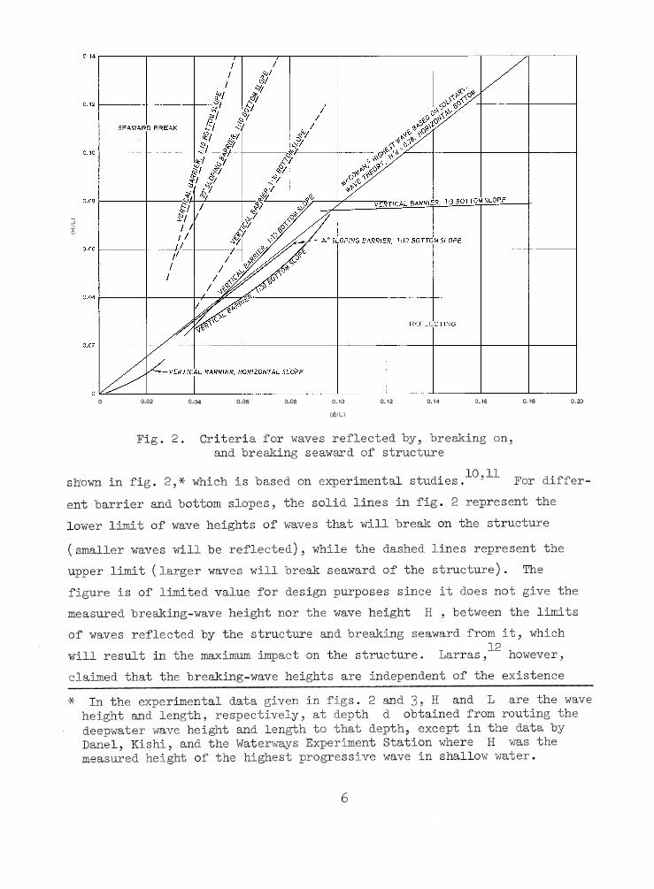
Fig. 2. Criteria for waves reflected by, breaking on, and breaking seaward of structure
shown in fig. 2,* which is based on experimental studies.10’1'1' For different barrier and bottom slopes, the solid lines in fig. 2 represent the lower limit of wave heights of waves that will break on the structure( smaller waves will be reflected), while the dashed lines represent theupper limit (larger waves will break seaward of the structure). Thefigure is of limited value for design purposes since it does not give themeasured breaking-wave height nor the wave height H , between the limitsof waves reflected by the structure and breaking seaward from it, which
12will result in the maximum impact on the structure. Larras, however, claimed that the breaking-wave heights are independent of the existence* In the experimental data given in figs. 2 and 3? H and 1 are the wave
height and length, respectively, at depth d obtained from routing the deepwater wave height and length to that depth, except in the data by Danel, Kishi, and the Waterways Experiment Station where H was the measured height of the highest progressive wave in shallow water.
6

0 0.10 0.20
(d/L)
Fig. 3* Selection of design wave breaking on structure
of a vertical barrier on a sloping bottom. This suggests the use of the criteria on waves breaking on a slope with no barrier present (i.e. zero reflection) for the selection of the design wave breaking on the structure.
11. The criteria on waves breaking on a slope with no barrier present are shown in fig. 3> where H is the wave height, d is the water depth at which the waves will start breaking, and L is the wavelength in water depth d . The figure shows the results of analytical and experimental studies^5 ^ on the highest progressive wave in shallow water,
5the results of analytical studies on the highest wave based on the13solitary-wave theory,. empirical relations, and flume data from the Water-
1 hways Experiment Station and Iversen. In fig. 3 the relations between d/L and H/L obtained by McCowan, Miche, Danel, Kishi, and the U. S. Navy Hydrographic Office are for flat bottom slopes, that obtained by the Waterways Experiment Station are for a bottom slope of 1:50, and those by Iversen are for bottom slopes of 1:10, 1:20, 1:30, and 1:50. Fig. 3 shows that
7

(a) the results of the investigations are in fair agreement and may be considered adequate for engineering purposes, and (b) for the same d/L ratio, the wave height at breaking increases with an increase in the bottom slope.^
1512. Mitsuyasu studied the height of the breaking wave that resulted in the maximum impact force on a vertical barrier placed on bottom slopes of 1:15, 1:30, and 1:50. His results also are shown in fig. 3and indicate that (a) for the same d/h ratio, the wave height at breaking increases with an increase in the bottom slope, which is in agreement with the results obtained by Iversen, and (b) for the same d/L ratio, the wave height at breaking is larger when a vertical barrier is present. Garcia's flume results,1^ also shown in fig. 3 5 are in fair agreement with those obtained by Mitsuyasu.
13. A possible explanation of the larger breaker heights obtained by Mitsuyasu and Garcia may be the wide range of wave heights that will break on the structure for a given d/L ratio (see fig. 2, in which the solid lines represent the lower limit of wave heights of waves that will break on the structure, while the dashed lines represent the upper limit). The breaker heights obtained by Mitsuyasu"*"'’ and Garcia^ were those that resulted in the maximum impact on the vertical barrier and are very likely to fall somewhere in the wide range of wave heights that will break on the structure, i.e. between the lower and upper limits. For waves breaking on a slope with no barrier present, such a range does not exist since the wave height at breaking was selected as the one at which instability of the wave form first appeared.
ll+. Flume tests are in progress at the Waterways Experiment Stationfor the selection of the design wave breaking on and reflected by rubblestructures. Selection of the design wave based on the economic life ofthe structure will not be discussed in this report. For information re-
17garding this subject, the reader is referred to McLaughlin and Anton andl8to Kreeke and Paape.
8

PART III: WAVE REFLECTION COEFFICIENTS OF STRUCTURES
15. The wave reflection coefficient of a structure (H^/i l ) is a function of the wave steepness, the relative depth of water in front of the structure, the angle of wave approach to the structure, and the shape, slope, roughness, and permeability of the structure. Several flume studies of wave reflection coefficients have been madet^ -
16. Miche assumed that the reflection coefficient X is composed of two factors5 X^ and X^ 9 the first depending on the roughness of the reflecting surface and the second being a function of the geometric shape of the reflecting surface. The reflection coefficient is obtained as the product of the roughness and the shape factors as follows:
^ = \ • X2 (1)
According to Miche, the factor X^ is independent of the inclination of the reflecting plane but is dependent on its roughness and permeability.Even for smooth surfaces, does not seem to exceed a value of 0.8 to 0.9. For a very rough surface, i.e. stepped slope, Miche gave the value of X = 0.33 5 and for a regular slope of rocks, he recommended X^ = 0.3 to 0.6 . According to the same author, the shape factor X, is dependent on both the inclination p of the reflecting wall (in relation to the horizontal) and the steepness of the waves in deep water ct . The maximum steepness of waves that are completely reflected (X^ = l) from a planehaving an inclination p is given by equation 2 and plotted in fig. k .
a =M2p sin pit it (2)
Waves with steepness larger than aM break partially and are partially reflected. Miche proposed the use of the following values for X, :
For a o 1 “M ’ X2 = 1For ao > % > ^ - -a 0MThe relation between )C = — and the inclination of the reflecting wall
oP is shown in fig. 5 for a value of ^ = 1 . Miche's approach is
9

0 A ± A A A A A A A A (HORIZ./v e r t i c a l )2 1 2 1 2 1 1 1 1 1
7Fig. U. Slope of impervious beach (Miche )
_ j_ A 2 Z A A A A a A A A 1AC OT ^ ” 1 4 2 4 1 2 1 1 1 1 1 1 1
rv
Fig. 5* Reflecting capacity of impervious beach (Miche')

considered satisfactory for engineering purposes and has been verified by21 22flume experiments conducted by Healy and by Greslou and Mahe.
17. Data from figs. 6, J, and 8, which show the relation between the
_L _L J_ JL -L ' 2_ _1 A B O T T O M SLOPE30 10 5 3 2 3 1 1
P = I------------ '------------- 1------------- 1-------------- 1------------- 1-------------- 1------------- 1-------------- 1------------- I—0° 10° 20° 30° 40° 50° 60° 70° 80° 90°
Fig. 6. Wave reflection coefficient, for smooth wall, as function of wave steepness and bottom slope (he Mehaute,2?)
Fig. 7- Wave reflection coefficient as function of wave steepness and relative depth of water in front of smooth vertical wall (from experiments by Domzig^3)
11
HWAVE STEEPNESS <r = —
L

0 0.01 0.02 0.03 0.04 0.05 0.06 0.07WAVE STEEPNESS (a, FOR EXPERIMENTS BY STRAUB24 AND
aQ, FOR EXPERIMENTS BY MATTSSON26)
Fig. 8. Wave reflection coefficient, for rubble-mound structures, as a function of wave steepness and rough
ness and permeability of reflecting surface
wave reflection coefficient and the wave steepness and the bottom slope, the wave steepness and the relative water depth in front of the structure, and the wave steepness and the roughness and permeability of the reflecting surface, can be used to estimate the wave reflection coefficient. If such data are inadequate for predicting the wave reflection coefficient for a particular structure, the relations suggested by Miche and presented in paragraph 16 can be adopted.
12

PART IV: PRESSURES ON SEAWALLS AND BREAKWATERS CAUSEDBY NONBREAKING WAVES REFLECTED BY THE STRUCTURE
18. Progressive waves reflected by a structure without breaking are either totally or partially reflected depending on the wave steepness, the relative depth of water in front of the structure, the angle of wave approach to the structure, and the roughness, permeability, shape, and slope of the structure. To determine the magnitude and distribution of the pressures caused by reflected waves, one first has to determine the mean level of the reflected wave above still-water level (swl); the wave pressures at different elevations are then determined from the pressure equations given below.
19. To the second order of approximation, the elevation of the water surface based on the Lagrangian system is given by:"^
Mean Level of a Reflected Wave Above Still-Water Level
sinh m(d + yQ)[(l + X) sin kt sin mxsinh md o
+ (l - X) cos kt cos mx D] + Wsinh 2m(d + y Q)
sinh md
2tanh md)
p p '-WO £-lUA+ (1 - X) cos kt + ----- p-2-
k sinh mdcos 2mxo (3 cos 2kt - tanh2 md)
+ 00
20. The elevation of the water surface at the vertical wall is obtained from equation k for x q = h /k and yQ = 0 ; therefore,
13

Hy = (l + X) sin kt + mH2~TT coth md (1 + X)'
X ( sin^ kt 3 cos 2kt + tanh md\ + ^ ^ sinh2 md /
2
I 2 _ , 3 cos 2kt - tanh mdX [ cos kt - ---------- 2-------b sinh md
(5)
The elevations of the wave crest y^ and the wave trough y ^ can be obtained from equation 5 by substituting t = T/b and t = 3^/b , respectively; therefore,
ycr = f C1 + x) + ^ coth md (i + xy
X 1 _ -3 + tanh md J + ^ ( 3 + tanh mdU sinh md h sinh md
(6)
- I ( l + x) +trmH2“S~ coth md (i + xy
X ^ -3 + tanh md j + ^ ^2 / 3 + tanh mdU sinh md k sinh md
(7)
21. It follows from equations 6 and 7 that the mean level of a re-y + y.17 cr 17 trfleeted wave above swl Ah is equal to --- ----- ; i.e.,
Ah = coth md (1 + X)2( 1 + 3 mdb sinh md
+ ( 1 - x)2 ( 3 + t a n g md4 sinh md
(8)
Equations of Wave Pressure
22. Based on the Eulerian system of coordinates, Bernoulli's classical equation of pressure is :

7 = - g y -
2-|y, + f(t) - H2 ^ (9)
The equation of wave pressure in front of a structure can be deduced from equation 9 as
P7
, H cosh m(d + y) r/n , v\ • n j_-y + — ------f * 1 [ (1 + X) s m kt sin mxJ 2 cosh md L v '
mH2+ (l - X) COS kt COS mx] - rry--— -- -----:-- -v * 16 smh md cosh md
( 2 2X \ ( l + X) cos kt [cosh 2m(d + y) + cos 2mx - 1]
2 2+ (l - X) sin kt [cosh 2m(d + y) - cos 2mx - 1]
+ (l - X sin 2kt sin 2mx|
3mH cosh 2m(d + y) r/n , v 0i j. 0- ----- r--*----- sL-z— [ (1 + X ¿cos 2kt cos 2mxsinbr md cosh md
2+ (l - X'^sin 2kt sin 2mx] + ^ — tanh md cos 2kt (10)
23. For a pure standing wave (complete reflection), the pressure is calculated by substituting X = 1 in equation 10; therefore,
p , TT cosh m(d + y) . . ,— = -y + H ---------- 7 v *-'■ sm k t sm mx7 17 cosh md
1 cos kt£ mH sinh md cosh md [cosh 2m(d + y) + cos 2mx - 1]
- mH^ ■cP.sfr-....P1.(A * y.). cos 2kt cos 2mx sintr md cosh md
+ I mH2 tanh md cos 2kt (11)
Equation 11 was deduced by Biesel.28
15

2 k . In the Lagrangian system of coordinates, equation 10 becomes:sinh my
-y + ö —r—;--3--- r— t [ (l + X) sin kt sin mxJ o 2 sinh md cosh md o^2. sinh my
+ (l - X) cos kt cos mx ] - rr^1- --- s— —° J sinh md
( / 2 COS 2mXX [ (l + X) < cosh m(2d + yQ) i b sin kt + --- — -( \ cosh md
+ b tanh md sinh m(2d + y ) (l - 3 sin kt)
+ 3 cos 2kt cos 2mxcosh myo 2 cosh m(d + yQ). -, 2 cosh md.sinh md
/ P cos 2mx ^+ [k cos kt - --- g— -
\ cosh md)
- ( 1 - 3 cos^ kt)
i
+ 3 cos 2kt cos 2mx‘cosh myQ 2 cosh m(d + yQ)sinh md cosh md
+ 6(1 - Y ^) s in 2kt sin 2mxcosh myQ 2 cosh m(d + yQ)sinh md cosh md (12)
25. For a pure standing wave, the pressure is calculated by substituting X = 1 in equation 12; therefore,
E =7sinh my
yo ^ sinh md cosh md sin kt sin mx
mH2 slnh " o i- - 5 ------------------- § ---------- )sinh md (
. 2-g----- ---< cosh m(2d + yQ) [U sin kt +
2+ b tanh md sinh m(2d + y ) (l - 3 sin kt)
cos 2mxcosh md>
+ 3 cos 2kt cos 2mxcosh myQ 2 cosh m(d + y )
_sinh md cosh md b (13)
Equation 13 was given by Miche. To the first order of approximation, equation 13 reduced to that given by Sainflou^ as follows:
16

sinh my"D ° O— = -y + H — 7— ;-------- --- r sin kt sin mx (lb)7 17 o s m h md cosh md o ' 7
Example#
26. Calculate the maximum wave pressure to which a steel sheet pile caisson breakwater will be exposed, knowing that the water depth d at the location where the breakwater will be constructed is equal to 25 ft (referred to swl), the fetch length F = 125 nautical miles, the maximum wind speed U = 28 knots, and the maximum wind duration t = 12 hr.
27. From fig. 17, page 19, of reference 29, for F = 125 nautical miles, U = 28 knots, and t = 12 hr, we obtain a significant wave height(Hp) = 11.5 ft and a significant wave period = 8.8 sec. It follows
o d dthat L = 397 ft, — = 0.063 , - = 0.107 , k = O .986 , and L = 233 ft.O Li Jj soAssuming that the breakwater will have a reflection coefficient X = 0.8 , we find from fig. 1 herein (page 5) that for d/L = 0.107 the maximum clapotis will have a wave steepness a. — 0.063 ; consequently, H = 14.7 ft. At the location of the breakwater, assuming that the refraction coefficient and the friction percolation coefficient are both unity, the predicted sig
nificant wave height H = (Hp X kg = 11.5 x O .986 = 11.4 ft, which is lesso
than 14.7 ft, the limiting wave height that can be reflected by the structure. Therefore, the breakwater will not be subjected to breaking waves, and it should be designed to withstand the pressures caused by a reflected design wave having a wave height H = 11.4 ft and a wave period T = 8.8 sec.
28. To calculate the maximum wave pressure exerted on the breakwater for a design wave height H = 11.4 ft and period T = 8.8 sec, first the mean level of the reflected wave above swl Ah is calculated from equation 8 . Knowing Ah , the maximum wave pressure is calculated from equation 10. Using equation 8 for a reflection coefficient X = 0.8 , we obtain Ah = +5.5 ft (swl). From equation 10 for a reflection coefficient X = 0.8 , we obtain the following maximum wave pressures at a water depthd = 25 ft (swl)
17

Order of Appr oximat i on
First
Wave Pressure, lb/ft Under Under
Wave Crest Wave Trough 33.54 16.46
2
Second 31.94 13.40
2 9 . It can be seen from the above tabulation that the use of the first order of approximation in calculating the wave pressure gives conservative results and may be considered adequate for most engineering purposes. However, for an optimum design, the use of the second order of approximation, which is in closer agreement with actual pressures measured and gives smaller wave pressures than those computed using the first order of approximation, is recommended. The wave pressure diagram, which shows the distribution of the wave pressure for nonbreaking waves on vertical- wall structures for both the first and second orders of approximation, is similar to that given on page 250 of reference 2 9.
18

PART V: PRESSURES ON SEAWALLS AND BREAKWATERS CAUSED BYWAVES BREAKING ON TEE STRUCTURE
30. Waves breaking on structures are known to cause impact pressures of very great intensity but of short duration, known as shock pressures, followed by secondary pressures of less intensity and longer duration, asshown in fig. The phenomenon of shock pressures has been studied byseveral investigators. 3,^,11,12,16,30-U3
16The phenomenon of secondary pres-
sures has been studied by Garcia, who found that they are of the order of
T I M E - -------
Fig. 9- Typical pressure-time curve for waves breakingon structure
magnitude of clapotis pressures and therefore can be predicted from the wave pressure equations given in Part IV herein.
31. The different expressions relating the shock pressures to the wave characteristics as formulated by some of the above-referenced investigators are as follows:
30 PGaillard p = p ( U + U ) (is)-hn v w oy K
19

XX- -31Hiroi p = PU2 m oKandiba and
Toukholka3^ -m = 0.8pfw
33Trenjoukhinn = 0.2 (U + tons/m^m
T - 3 ^Lira o = 2PU2 -m o
Molitor35 p = o .9p (u + U /m v w o7
37Bagnold
Q OHansen-3
3Minikin
Hayashi .and Hattori^
Rundgren
Nagai^
Garcia16
11
Waterways Experiment Station^
P - P -Mn o - 0.54p § l £ lb/ft:
p = pum ww 'S /„, 2Pm 101pg(dw + D) ■]-) T 11/ftw D LD
o = 2PU2 ■m wH
Pm = ? Ho [K1^-o +K2)
f l 2 \1/3I Æv H Ip = 300 l 0.051■m
P,m
x D L/ ^ Cm"
= 50(pg)2/3 E1/3 lb/in.2
P™ = PBCB P„C„U_m PACA + PBCB A A W
MinikinTs Formula
(17)
(18)
(19)
(2 0)
(21)
(22)
(23)
(210
(25)
(2 6)
(27)
(2 8)
(16)
32. The formula by Minikin given above is widely used by engineers. Minikin combined shock-pressure results with his own experience and developed an empirical formula, in terms of the wave dimensions and the water depth at the toe of the structure, as follows:
20

(23)d KrP = 101pg(d + D) —nti w ' B Lj
2where pm is the maximum shock pressure, lb/ft ; pg is the specific weight of sea water, lb/ft^; d is the depth of water at the toe of the structure, ft; D is the water depth in deeper water, one wavelength seaward of the structure, ft; is the height of wave just breaking on the structure, ft; and is the wavelength at a water depth D , ft. Theformula was originally derived for a composite-type breakwater consisting of a concrete superstructure atop a rubble structure. In that case d was the depth of water at the toe of the superstructure and D and were the water depth and wavelength, respectively, at the toe of the substructure, all in feet.
33. In the application of the Minikin formula, the maximum pressure is assumed to act at the swl and to decrease parabolically to zero at points one-half the breaking-wave height above and below the swl. To this dynamic pressure, the hydrostatic pressure measured from an elevation above swl equal to H^/2 is added to give the total pressure on the structure.
3^. The Minikin formula has certain limitations and is believed to be unsatisfactory for estimating shock pressures caused by waves breaking on structures because:
a. It is not dimensionally homogeneous.b . It is very dependent on the bottom bathymetry in front of
the structure, e.g., where no substructure is present the formula is adapted by using the depth of water at the structure as that at the toe of the structure d , and the deeper-water depth and wavelength (D , L-n) as values obtained one wavelength seaward from the structure. This gives much higher values of dynamic pressures for flat bottom slopes than for steep ones. It was suggested in reference 29 that adaptation of the formula be limited to slopes steeper than 1:15 or possibly 1:10 (i.e. for slopes flatter than 1:15, the values of D and Lq substituted in the formula should be those obtained for a 1:15 bottom slope).
£. In applying the formula, the dynamic pressure computed is considered to be of a static nature; it is added to the hydrostatic pressure to obtain the total maximum pressure for which the structure should be stable. This may result in large impractical cross sections of the structure, especially for those to be located on flat bottom slopes.
21

Laboratory experiments conducted at the Waterways Experiment Station showed that shock pressures may be larger in magnitude than those calculated using the Minikin formula, which makes the formula unsafe for calculating the stresses in the structure, The Waterways Experiment Station experiments also showed that shock pressures have a short duration and occur only on some spots of the structure, which makes it unrealistic to consider that they are of a static nature and to use them for calculating the stability of the structure as a whole.
The Waterways Experiment Station Formula
35. Shock pressures recorded in laboratory experiments conducted at the Waterways Experiment Station in 1965 were considerably higher than those predicted by any of the formulas given in paragraph 31 except for that by the Waterways Experiment Station (equation 28). The Waterways Experiment Station formula is based entirely on analytical considerations and is believed to describe best the phenomenon of shock pressures exerted on coastal structures. The development of this formula is presented in the following paragraphs.
36. Violent disturbances such as those resulting from impact on solids differ greatly from the linear phenomena of sound or light. In contrast to the latter, their propagation is determined by nonlinear differential equations, and as a consequence the familiar laws of superposition, reflection, and refraction cease to be valid and other features appear, among which the occurrence of shock fronts is of particular interest.Across the shock fronts the medium undergoes sudden and often considerable changes in velocity, pressure, and temperature.Flow involving discontinuous processes
37. Two types of discontinuity surfaces are distinguished here-- contact surfaces and shock fronts. Contact surfaces are surfaces separating two parts of the medium with no flow through the surface. Shock fronts are discontinuity surfaces that are crossed by the flow. The discontinuityconditions can be derived from the principles of conservation of mass,
1+1*momentum, energy, and entropy.38. Assume a column of fluid in a tube. The column covers at the
22

time t the interval aQ (t) < x < a^(t) , where aQ (t) and a^(t) denote the positions of the moving particles that form the ends of the column, and the flow is supposed to be continuous at the ends of the column. Therefore, for the column, the basic principles of conservation of mass and momentum can be expressed as follows.*
a.
b
Conservation of mass.
_d_dt
a (t) o v J
Conservation of momentum.
apt)pdx = 0 (33)**
_d_dt pudx p(aQ,t) - p(al5t) (3U
a (t)
Equation 3 - assumes that the only forces acting are pressure forces and that consequently the rate of change of momentum of the column equals the total resultant force exerted on the column by the pressure on the two ends.
39. As long as u , p , and p are continuous and differentiable in the whole column, the dynamic equations of motion can be deduced from equations 33 and 3^. In the present analysis, however, it is assumed that in the moving column there is a point of discontinuity whose coordinate x = £(t) moves with the velocity £(t) = U ’(t) ; and we shall derive from equations 33 and 3 - relations between quantities at both sides of this point. All our integrals have the form
J =
o v '
a1 (t)
the integrand \|r being discontinuous at tion 35 leads to
\|/(x, t)dx
x = £ .
(35)
Differentiation of equa-
* For a detailed mathematical derivation of the equations appearing in the following pages, the reader is referred to reference k.
** Equations 293 30, 315 and 32 have been deleted.
23

/ I(t)_d_ _d_dt J ~ dt ^(x,t)dx
a (t) %
ax(t)t(x,t)dx + tQi(t) - i|r(a ,t)u(a .t)o o
a (t) ov J
+ \|/(a1 ,t)u(a1,t) - (36)
I4O, The quantities \|r and \|/ are the limits of \|/(x,t) as x approaches i from the sides x < i and x > £ , respectively. Equation 36 holds no matter how short the column is, so long as it contains x = | as an interior point. We now perform the limiting process, letting the length of the column approach zero. Since the first integral on the right side of equation 36 tends to approach zero, we obtain
is the flow velocity relative to the discontinuity surface. Thus, we derive from the two basic equations (equations 33 and 3*0 the following conditions at a shock front :
(37)
where
v. = u. - U T ,1 = 0 , 1 1 1 ’(38)
a. Conservation of mass.
(39)
b. Conservation of momentum.
(to)
From equations 38 and 39? equation Uo can be written as
2k

(la)2 2 p v + p = pn v, + p, = P o O “1 1 ^1
where P is the total momentum flux.Shock pressures
4l. Shock pressures that occur when a water mass (e.g, a breaking wave) hits a structure may be explained according to the mathematical model in fig. 10, which shows two shock fronts at A-A and B-B. The shock front at A-A is moving away from 0-0 (plane of impact between water and
+ VE DIRECTION OF VELOCITIES -----------------------------------------------------
B
P
A
P A
P t Pt
S T R U C T U R E S TR U C TU R E WATER W A TE R
B O A
F R O N T OF SHOCK WAVE P R O P A G A T E D IN S T R U C T U R E
P LA N gO F IM P A C T B ETW EE N W ATER AND S T R U C T U R E
FR O N T OF SHOCK WAVE P R O P A G A T E D IN W ATER
Fig. 10. Mathematical model of impact between water mass and structure (Waterways Experiment Station^)
25

structure) with a speed CA ; ahead of that front, the liquid is moving with a constant velocity u^ . The shock front at B-B is moving away from
behind it, the structure is moving with a constant velocity u£ . The densities of the liquid and of the structure ahead and behind the shock fronts A-A and B-B are pA and pA , and pB and p^ , respectively.The pressure behind both shock fronts is pT . Determination of CA can be made for the condition that the processes are adiabatic and the equation of state is known.
1+2. From equation 39> for the conservation of mass at A-A and B-B, it follows that
From equation 1*1, for the conservation of momentum at A-A and B-B, it follows that
0-0 with a speed C_ ; ahead of that front, the structure is at rest whileJD
m
-PBCB = P¿(u2 - CB) (3)
(5)Eliminating p* from equations k2 and kb yields
X jl
PT = PA(ux + CA)(Ul - u p ( 1.6 )
Similarly, eliminating p' from equations ^3 and b yieldsJD
( ^ 7 )
Eliminating from equations 1+6 and 1+7 results in
26

PT “ PA (ux + C J + PA (U1 + CA )ulB Bu.,
Since — « 1 , equation b8 reduces to CA
PBCBPA°A + PBCB_ PaCaU1
m
43. The duration of the shock pressure is the time taken by a -wave to travel, with the speed of sound in water , from the point of impact to the nearest free surface, then back to the point of impact. When traveling from the point of impact to the free surface, the wave is a compression wave. When the wave reaches the free surface, the compression of the water is relieved and the wave is reflected as a tension wave. The tension wave travels back to the point of impact. When it reaches the point of impact, the compression of the structure is relieved.
Experimental Verification of the Waterways Experiment Station formula
kk. Experiments conducted at the Waterways Experiment Station^ consisted of accelerating a plate into a 3- by 3- by 6-ft steel tank that was filled with water. Plastic, aluminum, and steel plates of different masses were dropped onto the water surface in the tank, and the shock pressures developed were measured by piezoelectric pressure cells mounted in the plate. The plates were dropped in such a manner that at the moment of impact their surfaces were almost parallel to the water surface. In the model, the plate represented the structure and the water surface represented the breaking wave.
^5. The experimental data obtained were analyzed in the light of three analytical approaches, namely, shock pressures that are due to (a) the compression of a thin layer of air between the plate and the water surface at the moment of impact, (b) an instantaneous momentum exchange between the plate and the water mass, and (c) a water hammer phenomenon as given by equation It was concluded that shock pressures occur only atsome spots of the structure and are best described as.a water hammer phenomenon. Fig. 11 shows the Waterways Experiment Station experimental data; for each recorded maximum pressure p^ , its duration t and its ratio to the
27

SE
C
Fig. 11. Results of experiments on shock pressures conducted at Waterways Experiment Station^

corresponding theoretical pressure p j predicted from equation 49 * are plotted. The large scatter in the data is to be expected and is discussed in reference 4, to which the reader is referred for further details of the Waterways Experiment Station study.
46. Fig. 11 shows that (a) the ratio between the maximum shock pressure recorded and the corresponding one predicted from equation 49 has a mean value of 0.046 * and (b) the maximum shock pressure recorded reached as much a s '54 percent of the corresponding theoretical one. It is believed that the presence of entrapped air between the accelerated plate and the water surface at the moment of impact prevented the occurrence of pressures as high as p^ . The frequency distribution of the ratio p ^ P f is given in fig. 12 and shows that 0.025 is the most frequent value of this ratio.
Fig. 12. Frequency distribution of ratio between maximum shock pressure recorded at the Waterways Experiment Station^- and corresponding theoretical one predicted from the Waterways Experi
ment Station formula
29

1 2 5 10 20 30 40 50 60 70 80 90 95 98 99 9 9 .8 9 9 .9 99 .99C U M U L A T I V E P E R C E N T A G E F R E Q U E N C Y
Fig. 13. Cumulative percentage frequency of ratio between maximum shock pressure recorded at the Waterways Experiment Station^ and corresponding theoretical one predicted from the Waterways Experiment Station formula
1+7. Fig. 13 shows the cumulative percentage frequency of the P^/Pp ratio plotted on arithmetic probability paper and based on 380I+ observations; the probability that Pjj/Pip will be less than 0. 54 is 99*99 percent. However, a coastal structure designed for an economic life of 25 years may be subjected to as many as 80 million waves (assuming an average wave period of about 10 sec), and it is reasonable to assume that at least one of these waves will hit the structure with the ideal condition for generating shock pressures at one spot as high as p , . The ideal condition for the occurrence of a shock pressure as high as p , is the absence of entrapped air at the plane of impact between the front of the breaking wave and the structure at the moment of impact.
1+8. The duration t of the shock pressures recorded at the Waterways Experiment Station varied from 0.0003 to 0.0125 sec with a mean value of 0.0022 sec (fig. ll), and a most frequent value of 0.0011 sec (fig. 14). The data in fig. 11 are widely scattered and, when fitted by the least squares method, show a slight tendency for t to decrease for increasing
30

0 0.002 0.004 0.006 0.008 0.010 0.012 0.014
t, SEC
Fig, lb. Frequency of duration of shock pressure recorded at the Waterways Experiment Station^
values of P /Pr-p • This suggests that the closer the recorded pressure to the theoretical one? the shorter its duration. This has been confirmed by special tests which are discussed in reference k.
k9. Fig. 15 shows the cumulative percentage frequency of the duration of shock pressures, plotted on arithmetic probability paper; the probability that t will be less than 0.012U sec is 99*99 percent. For such short durations5 it is believed unrealistic to add the dynamic pressure to the hydrostatic pressure to obtain the total instantaneous pressure on the structure, as suggested by Minikin.
31
%

1 2 5 10 20 30 40 50 60 70 80 90 95 98 99 99.8 99.9 99.99CUMULATIVE PERCENTAGE FREQUENCY ^
Fig. 15. Cumulative percentage frequency of duration of shock pressures recorded at the Waterways Experiment Station1
32

50. Since shock pressures have a very short duration, especially those having a value close to p , and occur only on some spots of the structure, it is believed that:
a. They should not be considered for determining the stability of the structure as a whole, i.e. with respect to sliding and overturning.
b. They may be absorbed by massive structures such as concrete seawalls and breakwaters.
£. They may cause cracks in the massive shell structures such as steel caissons filled with rock; if the filling material is sand or small rock, it may leak out and endanger the stability of the structure. Therefore, the thickness of the caisson shell should be adequate to withstand the shock pressures to which the structure may be exposed.
d. They may affect the stability of less rigid structures of less width that have natural frequencies within the range of duration of the shock pressures.
Example
51. For the example introduced in paragraph 26, assume that thesteel sheet pile caisson breakwater will be located.in a water depth of15 ft instead of 25 ft. Therefore, (H^) , T^ , and Lq will remain un-
ochanged and will have the values of 11.5 ft, 8.8 sec, and 397 ft, respectively. It follows that = 0.0378 , — = O.O808 , k = 1.07^ , and-Li -Li SOL = 186 ft. Assuming that the structure will have a reflection coefficient X = 0.8 , we find from fig. 1 that for d/L = 0.0808 the maximum clapotiswill have a wave steepness h/L = 0.05 and consequently H = 9.3 ft.maxAt the location of the breakwater, the predicted significant wave height H = X k^ = 12mb ft, if the refraction coefficient and the friction percolation coefficients are assumed to be 1 .0, which is larger than 9.3 ft, the limiting wave height that can be reflected by the structure. Therefore, the structure will be subjected to breaking waves.
52. The highest wave that will break on the structures can be obtained from fig. 3; for d/l = O.O808 , the corresponding h/L = O.O65 (as obtained from the curve by Mitsuyasu for a 1:50 bottom slope with vertical barrier). The curve for a 1:50 bottom slope was used since no experimental
33

data are available for flatter bottom slopes. Hence, the breaking wave that will result in the largest impact will be 12.1 ft high with a period of 8.8 sec. The maximum theoretical shock pressures caused by such waves can be calculated from the Waterways Experiment Station formula as follows:
P nPBCB .
P flC + P- CL W lA A B B(^9 bis)
where2
p , = theoretical shock pressure, Ib/ftC. = acoustic velocity of sea water = 5000 ft/secCL = acoustic velocity of steel = 19?500 ft/secb Q
P = density of sea water = I .98 slugs/ft'3
= density of steel = 15-2 slugs/ft"3
u^ = impact velocity with which the wave hits the structure, ft/sec
The impact velocity u^ can be taken as the wave celerity since at the moment of breaking, the water particle velocity at the wave crest is equal to the wave celerity. Assuming that the breaking wave can be described by the solitary-wave theory, it follows that:
u^ = celerity of solitary wave = ^ + H) (50)
For g = 32.2 ft/sec , d = 15.0 ft, and H = 12.1 ft, we obtain from equation 50 a value for u^ of 29.5 ft/sec. Substituting the values of p^ ,p , C , , and u in equation ^9, we obtain a shock pressure p ofb A ^ b 2 1 1
28.2 x 10 Ib/ft . Therefore, the thickness of the sheet piles should be4 2adequate to withstand a pressure of 28.2 x 10 lb/ft . If it is assumed
that the maximum shock pressures that will occur on a prototype structure will be no larger than those obtained in the model tests (see paragraph U6), the design pressure would be about 50 percent of the calculated value. It is believed reasonable to assume such a risk and design on such a basis.
3 ^

PART VI: CONCLUSION
53. For the selection of the design -wave reflected by the structure, the relations between the wave characteristics and the local depth shown in fig. 1 can be used, where H is the wave height at the location of the structure if the structure were not there, and L and d are the wavelength and the water depth at the location of the structure, respectively. The solid curves in fig. 1 represent the maximum clapotis at a vertical wall, i.e. the case for total reflection where the amount of energy reflected by the structure is equal to the incoming wave energy, the structure being parallel to the wave crest. The dashed curves in fig. 1 represent the case of no reflection at all, i.e. the highest progressive wave that can be propagated in shallow water without breaking. For a partial reflection, e.g. a rubble structure, the highest wave may correspond to a curve in between the solid and the dashed curves in fig. 1, and may be interpolated between the two sets of curves according to the reflection coefficient of the structure, until sufficient experimental data are available.
54. For the selection of the design wave breaking on the structure, the relation between the wave characteristics and the local depth shownin fig. 3 can be used, where d is the water depth at which the waves willstart breaking and L is the wavelength at a water depth d . In fig. 3j
5H is the height of the highest progressive wave in the data by McCowan, Miche,^ Danel,^ Kishi,^ U. S. Navy Hydrographic Office,^ and Waterways
4 l4Experiment Station; the breaking-wave height in the data by Iversen; and the height of the breaking wave that results in the maximum impact on a vertical barrier in the data by Mitsuyasu^ and Garcia."^ Some of the deficiencies in the experimental data presented in figs. 1 and 3 will be overcome when the results from flume experiments in progress at the Waterways Experiment Station for selection of the design wave reflected by and breaking on rubble structures become available.
55. The wave reflection coefficient of a structure is a function of the wave steepness, the relative depth of water in front of the structure, the angle of wave approach to the structure, and the shape, slope,
35

roughness, and p e rm e a b ility o f the s tr u c tu r e , as shown in f i g s . 6, 7 , and
8. In e stim a tin g th e wave r e f le c t io n c o e f f i c ie n t , the data g iv en in
f i g s . 6, 7, and 8 can be used. I f th ese data are inadequate fo r p r e d ic t in g
th e wave r e f le c t i o n c o e f f ic ie n t of th e s tru c tu re a t hand, th e r e la t io n
suggested by M iche, and review ed in paragraph 16, can be used.
56. P ro g re ssiv e waves r e f le c t e d by a s tru c tu re are e ith e r t o t a l l y
or p a r t i a l l y r e f le c t e d . The magnitude and d is t r ib u t io n o f the p re ssu res
caused by waves r e f le c t e d by sea w a lls and breakw aters can be o btain ed from
equations 8 and 10 or 12, which have been v e r i f i e d e x p e r m e n ta lly . Equa
t io n s 8, 10 , and 12 , developed to the second order o f approxim ation, ta k e
in to account th e wave r e f le c t i o n c o e f f ic ie n t o f th e s tru c tu re , thus en ab lin g
the d esign engineer to c a lc u la te th e wave p re ssu re fo r t o t a l l y as w e ll as
p a r t i a l l y r e f le c t e d w aves.
57. Waves breakin g on s tru c tu re s cau se, a t some sp o ts, impact p r e s
sures o f g re a t in t e n s it y but o f short d u ratio n known as shock p re ss u re s ,
fo llo w e d by secondary p re ssu res o f le s s in t e n s i t y (o f th e order o f magni
tude o f c la p o t is p r e s s u r e s ) . The magnitude o f shock p ressu res can be ob
ta in e d from equation ky, which was a n a ly t i c a l ly developed and e x p e rim e n ta lly
v e r i f ie d a t th e Waterways Experiment S ta t io n . Since shock p re ssu res have
sh ort d u ra tio n (o f th e order o f a m illise c o n d ) and are b e lie v e d to occur
o n ly a t some spots on th e s tru c tu re i t fo llo w s th a t : (a) th e y should not
be co n sid ered fo r checking th e s t a b i l i t y o f th e s tru c tu re as a whole,
(b) th e y may be absorbed by f l e x i b l e s tru c tu re s such as sea w a lls and b re a k
w a te rs , (c) th e y may cause cracks in r i g i d s tr u c tu r e s such as s t e e l ca isso n s
f i l l e d w ith ro ck , and (d) th ey may a f f e c t the s t a b i l i t y o f s tru c tu re s th a t
have n a tu ra l fre q u e n c ie s w ith in the range o f d u ratio n o f shock p re ss u re s .
36
LITERATURE CITED
1. Sainflou, M., "Essai sur les digues maritimes verticales," Annal es des Ponts et Chaussées, Vol 2, No. 4, 1928, pp 5-48.
2. Miche, R., "Mouvements ondulatoires de la mer en profondeur croissante ou décroissante," Annales des Ponts et Chaussées, 1944, pp 25-78, 131-164, 279-292, 309-406.
3. Minikin, R. R., "Winds, Waves and Maritime Structures," Charles Griffin and Co. Ltd., London, England, 1950.
4. U. S. Army Engineer Waterways Experiment Station, CE, "Shock Pressure Resulting from the Impact Between Solids and Liquids," Vicksburg,Miss, (in preparation).
5. McCowan, J., "On Solitary Wave," London, Edinburgh, Dublin Phil. Mag. J.'Sci., Vol 32, No. 5, 1891, pp 45-58.
6. Michell, J. H., "On the Highest Wave in Water," Philosophical Magazine, 5th Ser. 36, 1893, pp 430-437.
. ✓ / / /7. Miche, M., Le pouvoir réfléchissant des ouvrages#maritimes exposes al'action de la houle," Annales des Ponts et Chaussées, Vol 121, No. 3, 1951, PP 285-319.
8. Danel, P., "Gravity Waves; On the Limiting Clapotis," National Bureau of Standards Circular 521, Nov 1952, U. S. Department of Commerce, Washington, D. C., pp 35-38.
9. Kishi, T., "The Possible Highest Gravity Waves in Shallow Water," Coastal Engineering in Japan, Vol 2, Committee on Coastal Engineering, Japan Society of Civil Engineers, Tokyo, Japan, 1959, PP 9-16.
10. Carr, J. H., "Breaking Wave Forces on Plane Barrier," ReportNo. E - 11.3, 1954, Hydrodynamics Laboratory, California Institute of Technology, Pasadena, Calif.
11. Rundgren, L., "Water Wave Forces," Bulletin No. 54, 1958, The Institution of Hydraulics, Institute of Technology, Stockholm, Sweden.
12. Larras, J., "Le deferlement^des lames sur les jetees verticales," Annales des Ponts et Chaussées, Vol 107, No. 5, 1937, pp 643-680.
13. U. S. Navy Hydrographie Office, "Breakers and Surf; Principles in Forecasting," H. 0. No. 234, Nov 1944, Hydrographie Office, U. S.Naval Department, Washington, D. C.
14. Iversen, H. W., "Laboratory Study of Breakers," National Bureau of Standards Circular 521, Nov 1952, U. S. Department of Commerce, Washington, D . C ., pp 9-32.
15. Mitsuyasu, H., "Experimental Study of Wave Force Against a Wall," Coastal Engineering in Japan, Vol 5, Committee on Coastal Engineering, Japan Society of Civil Engineers, Tokyo, Japan, 1962, pp 23-47.
16. Garcia, W. J., "A Study of the Pressure Caused by a Wave Breaking
37

Against a Vertical Barrier," 196k, U. S. Army Engineer Waterways Experiment Station, CE, Vicksburg, Miss, (unpublished).
17. McLaughlin, R. and Anton, M., "Study of Hurricane Barrier for Lower Narragansett Bay," Report No. 66, Feb 196^, Massachusetts Institute of Technology, Hydrodynamics Laboratory, Cambridge, Mass.
18. Kreeke, J. and Paape, A., "On Optimum Breakwater Design," Proceedings of the Ninth Conference on Coastal Engineering, American Society of Civil Engineers, 1964.
19. Caldwell, J. M., "Reflection of Solitary Waves," Technical Memorandum No. 11, Nov 19^9, U. S. Army Beach Erosion Board, Washington, D. C.
20. Shoemaker, H. J. and Thijsse, J. Th., "Investigations of the Reflection of Waves," International Association for Hydraulic Research Congress, Third Meeting, Grenoble, Paper 1-2, 1999«
21. Healy, J. J., "Wave Damping Effect of Beaches," Proceedings, Minnesota International Hydraulics Convention, St. Anthony Falls HydraulicLaboratory, 1953? PP 213-220.
✓ ✓22. Greslou, L. and Mähe, Y., "Etude du coefficient de^reflexion d'une houle sur un.obstacle constitue par un plan incline," Proceedings,Fifth Conference on Coastal Engineering, Grenoble, France, 195 -?Council on Wave Research, The Engineering Foundation, University of California, 1955-
23. Domzig, H., "Wellendruck und druckenzeugender Seegang," Mitt. Hann. Versuchsanst für Grund and Wasserbau, Heft -8, 1955-
2k. Straub, L. G., Bowers, C. E., and Herbrich, J. B., "Laboratory Tests on Permeable Wave Absorbers," Proceedings, Sixth Conference on Coastal Engineering 1958, Council on Wave Research, The Engineering Foundation, University of California, 1958.
25. Housley, J. G., "Location and Design of Wave Absorber, Gary Harbor, Indiana," Technical Report No. 2-509, June 1959, U. S. Army Engineer Waterways Experiment Station, Vicksburg, Miss.
26. Mattson, A., "Reflection of Gravity Waves," International Association for Hydraulic Research Congress, Vol 1, Paper No. 1.41, 19^3,pp 319-326.
27. Le Mehaute, B., "Wave Absorbers in Harbors," Contract Report No. 2-122, June 1965, U. S. Army Engineer Waterways Experiment Station, Vicksburg, Miss.
28. Biesel. F., "Equations generales au second ordre de la houle ir- reguliere," Houille Blanche, 1952, pp 372-376.
29. "Shore Protection Planning and Design," Technical Report No. h,3d ed., 1966, U. S. Army Coastal Engineering Research Center, CE, Department of the Army.
30. Gaillard, D. D., "Wave Action in Relation to Engineering Structures," 190^ (reprinted in 1935), The Engineer School, U. S. Army Corps of Engineers, Ft. Belvoir, Va.
38

31. Hiroi, L., MThe Force and Power of Waves/’ Engineer, 1920, pp I8U-I85
32. Kandiba, B. and Toukholka, Bericht Nr. kl. Bauweise senkrechter Hafendamme,” an de XIV Intern. Schiffahrtkongress, 1926, Cairo.
33« Trenjoukhinn, ’’Uber die Methode der Berechnung von Wellenbrechern mit senkrechter Wand,” Bauindustrie S905/07; 1926.
3^. Lira, J., ”Le calcul des brise-lames a parement vertical,” Le Genie Civil, Vol 90, No. 6, 1927, PP IU0-IU5.
35- Molitor, D. A., ’’Wave Pressures on Sea-Walls and Breakwaters,”Transactions, American Society of Civil Engineers, Vol 100, 1935; pp 984-1002.
36. DeRouville, A., Besson, P., and Petry, P., Etat actuel des etudes internationales sur les efforts dus aux lames,” Annales des Ponts et Chaussees, Vol 108, No. 7, July 1938, pp 5-113-
37- Bagnold, R. A., ’’interim Report on Wave-Pressure Research,” Journal of the Institution of Civil Engineers, No. 12, June-0ct 1939*pp 202-226.
38. Hansen, ’’Molen and Wellenkräfte an Molen hn deutschen Ostseegebiet,” Zentral Blatt der Bauverwaltung, 19 -0, S. ^23-^31-
39* Morison, J. R., ’’Wave Pressure on a Vertical Wall,” Technical Report No. HE-II6-298, 19^8, Institute of Engineering Research, University of California, Berkeley, Calif.
^0. Denny, D. F., ’’Further Experiments on Wave Pressures,” Journal of the Institution of Civil Engineers, No. 35; 1950-1951; pp 330-3^5*
kl. Ross, C. W., ’’Shock Pressure of Breaking Waves,” Proceedings,Fourth Conference on Coastal Engineering, 1953; Council on Wave Research, The Engineering Foundation, University of California,195 , p p 323-332.
b2. Hayashi, T. and Hattori, M., "Pressure of the Breaker Against aVertical Wall,” Coastal Engineering in Japan, Vol 1, Committee on Coastal Engineering, Japan Society of Civil Engineers, Tokyo, Japan, 1958, pp 25-37.
1+3. Nagai, S., ’’Shock Pressures Exerted by Breaking Waves on Breakwaters, Journal, American Society of Civil Engineers, Waterways and Harbors Division, Vol 86, June i960, pp 1-38.
kk. Courant, R. and Friedricks, K. 0., ’’Supersonic Flow and Shock Waves,” Interscience Publications, Inc., New York, 19 -8.
39

DISTRIBUTION LIST
No. ofOffice Copies Remarks
OCE (ENGAS-l) 2OCE (ENGCW) 2OCE (ENGSA) 1OCE (ENGTE-E) 1
Bd of Engrs forRivers & Harbors
Engr Center? Fort1
BelvoirEngr School Library
1
Fort Belvoir 1CERC 1Supv N. Y. Harbor 1LMVD 1 DEMemphis 1 Attn: Tech LibraryNew Orleans 1 Attn: Hydraulics Br, Engrg DivSt. Louis 0 Abstract of report to DE
0 Abstract of report to Chief, Hydraulics Br(lmsed-h )
Vicksburg 1 Engineering Division1 Hydraulics Branch
MRD 1 Attn: Chief, Hydraulics SectionKansas City 1 Attn: District LibraryOmaha 2 Office of Administrative Services (Library)
NAD 1 Attn: Engineering Division1 Attn: Project Planning Branch1 Attn: Mr. 0. F. Reyholec
Attn: Mr. A. G. Distefano1 Attn: Planning Division1 Attn: Civil Works Br, Construction-
Operations Division1 Attn: Mr. Morris Colen
Baltimore 0 Abstract of report to DE1 Attn: Engineering Division1 Attn: Planning & Reports Branch
New York 1 Attn: Engineering Division1 Attn: Basin & Project Planning Branch
Norfolk 1 Attn: Engineering DivisionPhiladelphia 1 Engineering Division, Attn: HAPEN-H
1 Engineering Division, Attn: NAPEN-D
1

Office RemarksNo. of Copies
NCD 1 Attn: LibraryBuffalo 1 Attn: Engineering DivisionChicago 1 Attn: Engineering Division
1 Attn: Project & Basin Planning Branch1 Attn: Operations Division1 Attn: Hydraulics Branch
Detroit 1 Attn: Library1 Attn: Engineering Division1 Attn: Basin Planning 8c Project Planning
BranchRock Island 1 DESt. Paul 1 Attn: Engineering DivisionLake Survey 3 Attn: Technical Library
RED 1 Attn: Hydrology Branch1 Attn: Planning Branch
NED 1 Attn: Planning Division1 Attn: Division Hydraulic Laboratory
Alaska 1 Attn: District Library1 Attn: Hydraulics Design Sectionl Attn: Planning 8c Reports Branch
Portland 1 Attn: District LibrarySeattle 1 Attn: Engineering Division
1 Attn: Planning BranchWalla Walla 1 Attn: Engineering Division
1 Attn: Planning 8c Reports Branch
ORD 1 DE1 Attn: Mr. A. J. Moors
Huntington l Attn: Library1 Attn: Hydraulics Branch
Louisville 1 Attn: Hydraulics BranchNashville l Attn: Hydraulics Branch, Engineering
DivisionPittsburgh l Attn: Engineering Division Technical
Library
POD 1 Attn: Tech Engrg Br, PODG-BHonolulu 1 Attn: District Library
1 Attn: Engineering Division1 Attn: Civil Works Branch
2

Office Remarks
SAD
Charleston
Jacksonville
Mobile
SavannahWilmington
SPD
Los Angeles
Sacramento San Francisco
SWDAlbuquerque Fort Worth Galveston
Little Rock Tulsa
WES
Wo. ofCopies ____________ _____ ___________________________
1 Attn: Engineering Division1 Attn: Planning Division1 Attn: Engineering Division1 Attn: Coastal Engineering Branch1 Attn: Project Planning Branch1 Attn: Chief, Canal Hydraulic Section1 Attn: Engineering Division1 Attn: Design Branch1 Attn: Water Management Section1 Attn: SAMEW-DV1 Attn: SAMEN-P2 Attn: Planning Branch1 Attn: Engineering Division1 Attn: Planning, Reports, & Program Branch
1 Attn: Chief, Technical Engineering Branch1 Attn: Planning & Reports Branch1 Attn: Library1 Attn: Engineering Division1 Attn: Coastal Engineering Branch1 Attn: Mr. R. E. Louden1 Attn: Mr. G. D. Ward0 Abstracts of report to:
Mr. Edward Koehm Mr. Robert S. Perkins Mr. Albert P. Gildea Project Planning Branch
2 District Librariank Attn: Library1 Attn: Mr. 0. T. Magoon
2 Attn: Library2 DE1 Attn: Librarian1 Attn: Librarian1 Attn: Engineering Division1 Attn: Project Planning Branch1 DE1 DE
3 DirectorAttn: Research Center Library
3

Automatic:Engineering Societies Library, Lew York, N. Y. 1Library, Div of Public Doc, U. S. Govt Print. Office, Washington, D. C. 1 Library of Congress, Doc Expd Proj, Washington, D. C 3Col. C. T. Newton 1Coastal Engineering Research Center, Attn: Ebba C. Everett,
Librarian 1Prof. J. W. Johnson, Univ of Calif., Berkeley, Calif. 1Defense Documentation Center, Alexandria, Va. 20
Exchange Basis:HOUILLE BLANCHE^ Grenoble, France (ENG-63) 1The Library, Nat'l Res Council, Ottawa, Canada (ENG-17) 1The Librarian, Ministry of Technology at Kingsgate House,
London, England (ENG-U6) 2The Inst of Civil Engineers, London, England (ENG-^7) 1Inst of Engineers, Sidney, Australia (ENG-162) 1APPLIED MECHANICS REVIEWS, San Antonio, Tex. 2Dept of Civil Engineering, The Univ of Arizona, Tucson, Ariz. 1Dr. Donald A. Sawyer, Auburn Univ, Auburn, Ala. 1Bureau of Reclamation 1Prof. A. J. Acosta, Hydrodynamics Lab, Calif. Inst of .Tech,
Pasadena, Calif. 1Scripps Inst of Oceanography, Univ of Calif., LaJolla, Calif. 1Engrg Lib, Univ of Calif., Berkeley, Calif. 1Central Records Library, Dept of Water Resources, Sacramento, Calif. 1 W. M. Keck Lab of Hydraulics 8c Water Resources, Calif. Inst of Tech,
Pasadena, Calif. 1Case Inst of Tech, Cleveland, Ohio 1Central Serial Record Dept, Cornell Univ Lib, Ithaca, N. Y. 1Engrg & Ind Experi St a, Univ of Florida, Gainesville, Fla. 1Price Gilbert Memorial Library, Georgia Inst of Tech, Atlanta, Ga. 1Gordon McKay Library, Cambridge, Mass. 1Gift & Exchange Division, Univ of 111. Library, Urbana, 111. 1Library, Iowa State Univ of Science 8c Tech, Ames, Iowa 1Engrg Experi Sta, Kansas State Univ of Agric 8c Applied Science,
Manhattan, Kans. 1Documents Room, Univ Lib, Univ of Kansas, Lawrence, Kans. 1Fritz Engineering Lab, Lehigh Univ, Bethlehem, Pa. 1Hydrodynamics Laboratory, MIT, Cambridge, Mass. 1University of Arkansas, Fayetteville, Ark. 1Mr. Robt T. Freese, Univ of Michigan, Ann Arbor, Mich. 1Engineering & Ind Research Sta, State College, Miss. 1College of Engineering, Univ of Missouri, Columbia, Mo. 1Univ of Missouri, School of Mines 8c Metallurgy, Rolla, Mo. 1North Carolina State College, Raleigh, N. C. 1Dept of Civil Engrg, Technological Inst, Northwestern Univ, 1
Evanston, 111.Main Library, Ohio State Univ, Columbus, Ohio 1Engrg Experi Sta, Oregon State Univ, Corvallis, Oreg. 1Dept of Oceanography, Oregon State Univ, Corvallis, Oreg. 1New York University, ATTN: Engrg Lib, University Heights,
Bronx, N. Y. 1
b

Exchange Basis: (Continued)McGill University, Montreal, Quebec, Canada (ENG-271) 1
Engrg Library, Pennsylvania State Univ, University Park, Pa. 1Periodicals Checking Files, Purdue Univ Libraries, Lafayette, Ind. 1Tennessee Valley Authority 1Research Editor, Texas Transportation Inst, Texas A&M Univ,
College Station, Tex. 1Office of Engineering Research, Publications, Univ of Washington,
Seattle, Wash. 1
Albrook Hydraulic Lab, Washington State Univ, Pullman, Wash. 1Engrg Lib, Univ of Wisconsin, Madison, Wis. 1Engineering Library, Stanford University, Stanford, Calif. 1Serials Acquisitions, Univ of Iowa Libraries, Iowa City, Iowa 1Lorenz G. Straub Memorial Library, Minneapolis, Minn. 1Director, Pacific Region, Dept of Public Works,
Vancouver, B. C-, Canada 1
Abstract of Report:CG,'Fourth U. S. Army, Fort Sam Houston, Tex., ATTN: AKAEN-OIPrinceton University River & Harbor Library, Princeton, N. J.Duke University Library, Durham, N. C.Princeton University Library, Princeton, N. J.Louisiana State University Library, Baton Rouge, La.The Johns Hopkins University Library, Baltimore, Md.University of Kansas Libraries, Lawrence, Kans.Laboratorio Nacional de Engenharia Civil, Lisboa, Portugal Dept of Civil Engrg, Univ of Tokyo, Buhkyo-ku, Japan Mr. Shigematsu Suzuki, Civil Engrg Res Inst, Hokkaido Development
Bureau, Nakanoshima, Sappo, Japan Commandant, USAREUR Engineer-Ordnance School, APO New York 09172 Mr. J. C. Harrold, k-216 Pennsylvania Ave., Apt. 2, Kettering, Ohio Water Information Center, Inc., Water Research Bldg., kk Sintsink
Drive, East, Port Washington, N. Y.Duke University, College of Engineering Library, Durham, N. C.Serials Record, Pennsylvania State University, University Park, Pa.
Send with Bill:Librarian, Dept of Public Works, Sydney, Australia 1
Announcement of Availability by Tech Liaison Branch:CIVIL ENGINEERING THE MILITARY ENGINEER ENGINEERING NEWS-RECORD
5

UnclassifiedSecurity Classification
DOCUMENT CONTROL DATA ■ R & D_(Securhy^clas^sUication^oi^titlej^body^oi^abstTac^and index ing annotation must be entered when the o ve ra ll report Is c la s s if ie d )
1. O R I G I N A T I N G A C T I V I T Y (Corporate author)
U. S. Army Engineer Waterways Experiment Station Vicksburg, Mississippi
2a. R E P O R T S E C U R I T Y C L A S S I F I C A T I O N
Unclassified2b. G R O U P
3. R E P O R T T I T L E
WATER WAVE FRESSURES ON SEAWALLS AND BREAKWATERS4. D E S C R I P T I V E N O T E S (Type o i report and in c lu s iv e dates)
Final report5* A U T H O R ( S ) ( F ir s t name, m idd le in it ia l, la s t name)
Adel M . Kamel«. R E P O R T D A T E
February 1 9 688«. C O N T R A C T O R G R A N T NO.
b. P R O J E C T NO.
7a. T O T A L NO. O F P A G E S
b77b. NO. O F R E F S
U9a. O R I G I N A T O R ’ S R E P O R T N U M B E R (S )
Research Report No. 2-10
9b. O T H E R R E P O R T NO(S) (Any other numbers that may be assigned this report)
10. D I S T R I B U T I O N S T A T E M E N T
This document has been approved for public is unlimited.
release and sale; its distribution
11. S U P P L E M E N T A R Y N O T E S
13. A B S T R A C T " “
12. S PO N S O R IN G M I L I T A R Y A C T I V I T Y
Office, Chief of Engineers U. S. Army
Several analytical and experimental studies on the highest gravity water wave that can be reflected by a structure, the highest progressive wave in shallow water, and the highest wave that will break on a structure were analyzed. This resulted in diagrams for the selection of the design wave reflected by or breaking on a structure. It was found that the height of the design wave depends on the characteristics of the deepwater wave, the wave reflection coefficient of the structure, the water depth at the structure, and the bottom slope and depth contours seaward of the structure. For the wave reflection coefficients of seawalls and breakwaters, experimental data available were analyzed, and an analytical approach is presented. This analysis resulted in diagrams for the determination of the wave reflection coefficient, which was found to be a function of the wave steepness, the relative depth of water in front of the structure, the angle of wave approach to the structure, and the shape, slope, roughness, and permeability of the structure. Equations, developed to the second order of approximation, for calculating the wave pressures on seawalls and breakwaters caused by waves reflected by the structure are presented.The equations take into account the wave reflection coefficient, thus enabling the design engineer to calculate the wave pressures for totally as well as partially reflected waves. An example illustrating the method of selecting the design wave and calculating the wave pressures is presented.
DD FORM« MO V •• 1473 R E P L A C E S DO F O R M 147». 1 JA N S4. W HICH IS
O B S O L E T E F O R A R M Y U S E . UnclassifiedSecurity C la ss ifica tion

UnefassifiedSecurity Classification
1 4 .K E Y W O R D S
L I N K A L I N K B L I N K C
R O L E W T R O L E W T R O L E W T
BreakwatersSeawallsWater wave forces
UnclassifiedSecurity Classification