4 – marine works 1. seawalls and breakwaters 1.1...
TRANSCRIPT

P. 1 of 30
Breakwater Layout
4 – Marine Works 1. Seawalls and breakwaters 1.1 Breakwaters • A breakwater is a structure employed to reflect and dissipate the energy of water
waves.
• They may be constructed to form a harbour or typhoon shelter and create
sufficiently calm water, thereby providing protection for safe navigation,
berthing and mooring of vessels, and other harbour activities.
There are three main types of breakwaters:
1. rubble mound breakwater
2. vertical breakwater
3. composite breakwater
1.1.1 Rubble Mound Breakwaters • A rubble mound breakwater is typically constructed with a core of quarry-run
stone.
• The core is protected from wave action by rock underlayers and an outer layer
composed of massive rocks (1500-4000 kg/unit) or specially shaped concrete
armour units.
• The breakwater is support on a prepared foundation on the seabed. (The
preparation of the foundations for breakwaters and seawalls is to be discussed in
the next section.)

P. 2 of 30
Dolos
Rubble Mound Breakwater
Concrete Armour Units

P. 3 of 30
Caisson Type Vertical Breakwater
Composite Breakwater
1.1.2 Vertical Breakwaters • A vertical breakwater is a vertically faced structure extending directly from
seabed level to resist wave attack.
• They are usually reinforced concrete caissons pre-fabricated in a dry dock.
• They are then transported to the site by flotation and sunk into the seabed
foundation.
• The inside chambers of the caisson are filled with earth or rock to increase its
mass.
1.1.3 Composite Breakwaters • A composite breakwater is a combined structure consisting of a vertical
structure placed on a rubble mound that is submerged at all tidal levels.
• This type of structure may be used as a breakwater in very deep water where the
volume of rock required for a rubble mound structure can be reduced, or
• when it is not practicable to design a vertical face structure to carry the design
wave loading to the full depth.

P. 4 of 30
1.2 Seawalls A seawall can be used as a soil retaining structure of reclamation or as an armouring
structure to protect a shoreline from erosion against wave and current actions. They
may be vertical or sloping.
There are four common types of seawalls used in Hong Kong:
1. Concrete Blockwork Seawalls
2. Caisson Seawalls
3. Wave Absorption Vertical Seawalls
4. Rubble Mound Sloping Seawalls
Remarks: Bermstones shall be ≥1000 kg/unit. Levelling stones shall be grade 75 rock fill material.
Concrete Blockwork Seawall
Foundation

P. 5 of 30 Caisson Seawall
Installation of Concrete Blockwork Seawall
1.2.1 Concrete Blockwork Seawalls Concrete blockwork seawalls are gravity structures made up of precast concrete
blocks. They are commonly used in Hong Kong because have the following
advantages: 1. Relatively low cost of construction.
2. Long history of satisfactory performance with negligible need for maintenance.
3. Flexibility to cope with some differential foundation settlement.
4. They can provide marine frontage for vessel berthing and cargo handling.
5. Damage from vessels in accidents is usually minor.
6. Incorporation of landings, pumphouses and drainage outfalls is relatively simple.
1.2.2 Caisson Seawalls Similar to a caisson breakwater, a caisson seawall is usually pre-fabricated then sunk
into its designated locations.

P. 6 of 30
1.2.3 Wave Absorption Vertical Seawalls • Vertical seawalls with solid face are highly reflective of wave energy. This
may not be acceptable inside a harbour as wave agitation will affect vessel
operation and navigation. • Wave reflection can be reduced by introducing wave absorption units on the
vertical seawalls. A vertical seawall contains a wave absorption chamber with
perforated front wall that allows flow into and out of the chamber.
Wave Absorption Seawall

P. 7 of 30
1.2.4 Rubble Mound Sloping Seawalls • The slope of the seawall is generally protected by rock armour. If the wave
condition renders the rock size not economically available in the market,
concrete armour units can be used as an alternative to protect the slope of the
seawall.
Rubble Mound Seawalls
Rubble Mound Seawalls

P. 8 of 30
Dredging of Marine Deposit
2 Preparation of foundations for seawalls and breakwaters: 2.1 Dredging 2.1.1 Fully dredge method for preparation of the foundations of seawalls or
breakwaters may involve totally removing the marine deposits and replacement
with sand or rubble fill in order to provide adequate foundation stability and to
prevent excessive settlement. Normally, dredging is stopped when a firm
stratum has been reached.
This method, though relatively
simple, requires the disposal of
dredged sediments, in particular
when the quantity is large. In
addition, removal of soil is
generally discouraged unless
there is strong justification
2.1.2 Partial dredge method – Partial removal of marine deposits, leaving the stiffer or
stronger deposits in place, reduces the dredging and fill quantities compared to
the full-dredge method. Partial dredging may be carried out in conjunction
with installation of vertical drains and staged construction.
The main purpose of vertical drains is to accelerate the consolidation of the
remaining soil so that the target settlement due to primary consolidation can be
achieved within shorter period (to be discussed in the next section).
Staged construction allows sufficient time for the marine deposits to consolidate
and gain strength between stages of construction. Partial dredging normally
requires longer construction period for consolidation to take place.
P. 9 of 30
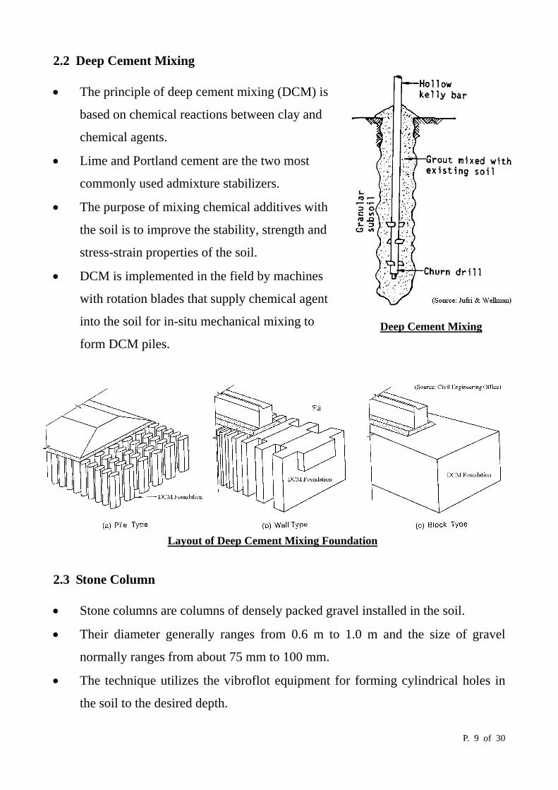
Deep Cement Mixing
2.2 Deep Cement Mixing • The principle of deep cement mixing (DCM) is
based on chemical reactions between clay and
chemical agents.
• Lime and Portland cement are the two most
commonly used admixture stabilizers.
• The purpose of mixing chemical additives with
the soil is to improve the stability, strength and
stress-strain properties of the soil.
• DCM is implemented in the field by machines
with rotation blades that supply chemical agent
into the soil for in-situ mechanical mixing to
form DCM piles.
2.3 Stone Column • Stone columns are columns of densely packed gravel installed in the soil.
• Their diameter generally ranges from 0.6 m to 1.0 m and the size of gravel
normally ranges from about 75 mm to 100 mm.
• The technique utilizes the vibroflot equipment for forming cylindrical holes in
the soil to the desired depth.
Layout of Deep Cement Mixing Foundation

P. 10 of 30
• Then gravel is poured into the hole in layer of about 300 mm each.
• For each layer, the vibroflot is used to compact and displace the gravel
outwards.
• Compaction is continued until the lateral resistance to the displacement of the
soil by the gravel is fully developed. (Alternatively, the gravel is pumped
through a supply duct to the bottom of vibroflot progressively.)
• The maximum practical length of stone columns is about 30 m.
Installation of Stone Column

P. 11 of 30
Layout of Stone Column Foundation
• By constructing stone columns in a square, rectangular or triangular grid pattern,
the ground is transformed into a composite mass of vertical, compacted granular
cylinders with intervening soil.
• This method provides the advantages of increasing the average shear strength
and decreasing the compressibility of the treated soil.
• Since gravel is a good drainage material, installation of stone columns in clayey
soil also accelerates the dissipation of excess pore water pressure and hence the
consolidation.
Vibroflot with delivery tube

P. 12 of 30
3. Reclamation 3.1 Purpose of Reclamation Reclamation may generally be carried out:
To provide land for essential major transport infrastructure.
To provide land for housing, community facilities and public open spaces.
To provide land for port and industrial uses.
To eliminate areas of badly polluted water and improve hydraulic conditions by
rearranging the coastline.
3.2 Reclamation Method 3.2.1 Drained Method The drained method leaves the soft marine deposit in place, and the consolidation is
usually accelerated by the use of vertical drains and sometimes with surcharge
preloading. Drained reclamation is usually carried out in the following sequence:
Sequence of Drained Reclamation

P. 13 of 30
By Marine Plant By Land Plant
Installation of vertical drains
a. Laying of geotextile on the seabed -
Geotextile may be laid on the seabed to separate the fill from the underlying soft
marine deposits, preventing migration of fines. It also enhances the stability of
the underlying marine deposits in supporting the loading of the reclamation fill.
b. Deposition of blanket layer
This blanket should consist of free draining granular material of about 2 m thick.
This granular layer works with the vertical drains to enable drainage from the
clayey deposits. It also acts as a capping layer to spread the load from the fill
during the filling operation.
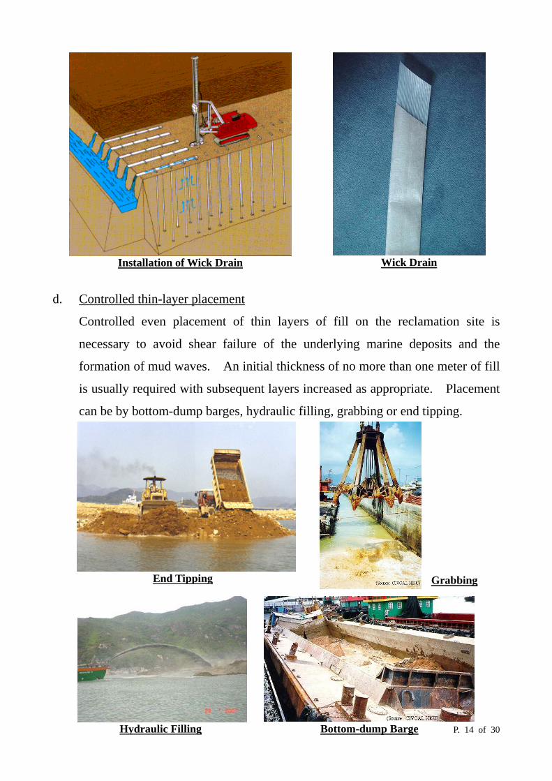
c. Installation of vertical drains (also known as wick drain or band drain)
The vertical drain was band-shaped with a plastic core enclosed by a non-woven
geotextile filter jacket. It functioned as a passage for water flow, to accelerate
the dissipation of pore water pressure during the consolidation of the marine
deposit layer. The band drains were installed in a triangular grid pattern with
1.5 m c/c spacing.
To commence the acceleration of consolidation earlier, the band drains are
usually installed over water using special marine plant just after laying of the
sand blanket. The vertical drains can also be installed after reclamation using
land plant.
P. 14 of 30
Installation of Wick Drain
Wick Drain
d. Controlled thin-layer placement
Controlled even placement of thin layers of fill on the reclamation site is
necessary to avoid shear failure of the underlying marine deposits and the
formation of mud waves. An initial thickness of no more than one meter of fill
is usually required with subsequent layers increased as appropriate. Placement
can be by bottom-dump barges, hydraulic filling, grabbing or end tipping.
Hydraulic Filling
End Tipping
Bottom-dump Barge
Grabbing

P. 15 of 30
3.2.2 Fully Dredged Method In fully dredged method, all marine and alluvial clays or silts are removed by
dredging and replaced with fill.
Pros:
• The method is relatively simple.
• Settlement of the reclamation fill is more quickly and more predictable.
Cons:
• Can be expensive where thick layers of soft deposits exist.
• Causing mud waves during dredging
• Disposal of dredged sediments, particularly for contaminated mud may be
problematic.
This method is generally discouraged unless there is strong justification.
3.2.3 Partial Dredged Method
• The partial dredged method involves partial removal of marine or alluvial
deposits, leaving the lower, stiffer or stronger deposits in place.
• The remaining marine deposits shall be treated as that in the drained method.
• It fact it is the combination of the drained method and fully dredged method, so
it combines and neutralizes both the pros and cons of the two methods.

P. 16 of 30
Suction hopper dredger
3.3 Fill Materials Fill materials for reclamation includes public fill, marine sand fill and crushed rock,
but public fill and marine sand fill are the most commonly used types of fill in local
conditions.
3.3.1 Public Fill • Public fill is the inert portion of construction and demolition material from
private and public developments and demolition sites.
• Because of the shortage of areas to accommodate the public fill generated by the
construction industry, priority should be given to its use.
• It is also the government policy to maximize the use of public fill in reclamation
projects.
3.3.2 Marine Sand Fill • Sophisticate dredgers are use to
obtain the sand from a marine
borrow area.
• Since the mobilization costs are high, the size of the project must be large
enough to justify the use of sophisticated dredgers.
• Plant such as trailing suction hopper dredgers may dredge marine sand fill very
fast and at relatively low costs, particularly when the borrow area is close to the
reclaimed site.
• These dredgers can deposit marine sand in the reclamation by bottom dumping
or by hydraulic pumping.
• The rate of formation of reclamation can be very rapid compared to the use of
other types of fill.

P. 17 of 30
3.3.3 Rock Fill • Crushed rock from local land sources should not normally be used for
reclamation. It should be used as foundation materials or processed to produce
aggregate products, as far as possible.
• In case a works project involving large quantities of rock excavation and
removal, the surplus rock material can be used for reclamation.
• Where crushed rock over 250 mm is used, it should be placed in areas where no
building development will take place, to avoid impeding piling or excavation
works in the future.
3.4 Fill Treatment • Fill treatment processes are to speed up the consolidation of the reclaimed area
in order to reduce the long term settlement.
• It shall be noted that the settlement is contributed from both the existing marine
deposits and the newly reclaimed materials.
3.4.1 Surcharge Preloading • Surcharge preloading can be used to accelerate settlement of fill that would
otherwise occur more slowly.
• Monitoring of the consolidation of the fill will be carried out periodically.
• The surcharge should only be removed when the required settlement or increase
in strength has been achieved.
Surcharge Pre-loading Vertical Drains
Drainage Layer
Vertical Drain

P. 18 of 30
Free Fall Hammer
Free Fall Hammer
Craters Formed by Free Fall Hammer
3.4.2 Dynamic Compaction • Dynamic compaction involves repeated dropping of heavy weights onto the
ground surface.
• Large amounts of energy are transferred to the soil in the form of impact force
and waves, particularly shear waves.
• This results in a densely packed particle
arrangement.
• Dynamic compaction is suitable for use in most
soils except cohesive soil below the water table.
• The pounders used for dynamic compaction
may be concrete blocks, steel plates, or thick
steel shells filled with concrete or sand, and
may range from one or two up to 200 tons in
weight. Drop heights up to 40 m have been
used.
• Dynamic compaction can also be carried out
underwater.

P. 19 of 30 Vibro-compaction Method
3.4.3 Vibro-compaction • The vibro-compaction method is used to compact a thick layer of fill, particular
in reclamation.
• It is used for granular soils, in particular sand.
• This method is very similar to the stone column method except that no
additional granular material will be used to fill the borehole; instead the original
fill material is pushed back into the borehole.
• The vibroflot is penetrated into the fill and retracted in a controlled motion such
that a dense column of fill is formed.
• The compaction is carried out in a triangular grid pattern of 2.5 m to 4 m c/c
spacing.
• Effective compaction depth can be up to 35 m.
• Vibro-compaction is only applicable to granular materials of certain grading
properties.
• Vibro-compaction cannot effectively compact the surface few metres of fill and
therefore separate compaction of the surface layer will be required.

P. 20 of 30
3. Submarine Pipeline and Outfall
Submarine pipelines are pipelines laid under the sea for carrying public services and
utilities such as water, electricity, communication, oil, etc.. An outfall is a large
diameter submarine pipeline discharging wastewater directly into the sea. An
outfall may be laid on the seabed or bored under the seabed at some depth, or a
combination of both.
Tunnel Outfall 3.1 Pipeline Materials The diameters of the pipeline range from less than 0.1 m to above 4 m. The
materials that are used for submarine pipelines fall into five main categories:
Metal Weldable carbon steel
Grey or Ductile Iron
Concrete Reinforced concrete
Concrete surrounded steel pipe
Plastic Glass Reinforced Plastic (GRP)
High Density Polyethylene (HDPE)
Medium Density Polyethylene (MDPE)
Polyvinyl Chloride (PVC)
Unplasticised Polyvinyl Chloride (UPVC)
Flexible Armoured Pipe e.g. spiral wound steel armouring with UPVC lining and
rubber or plastic outer sheath
Proprietary Materials e.g. Corrugated HDPE

P. 21 of 30
3.2 Construction Methods There are several methods by which outfalls can be constructed, but are basically
variation of the following, which can be combined if appropriate:
a. Pipe-by-pipe method.
b. Bottom pull method.
c. Float and lower method
d. Immersed tube method.
e. Lay barge / Reel barge method.
f. Boring method
The choice of the above methods depends on the diameter, length and depth of the
pipeline being laid. Long sea outfalls have been constructed with diameters up to
4m, and lengths extending offshore to as far as 10 km and water depths approaching
100m.
3.2.1 Foreshore crossing For crossing foreshore, temporary works may be required, which may comprise:
a. Sheet pile cofferdams and open cut excavation to take the pipe. The seawall is
rebuilt following outfall installation.
b. A tunnel or thrust bore under a seawall with a sleeve pipe inserted to take the
main pipe.
c. Horizontal directional-drilled hole to install the pipe beneath the seawall.
Horizontal Directional Drilling

P. 22 of 30
3.2.2 Pipe-by-pipe method Pipes for this method of construction are usually precast in a factory, but in some
cases can be manufactured at a site specifically created for the purpose near to the
outfall location.
The pipes are lowered into their required position on the seabed or into a pre-dredged
trench from a crane or gantry mounted on a floating barge. Joints usually consist of
spigot and sockets with ‘O’ rings, although in some cases bolted flange connections
or proprietary mechanical systems can be employed. For large diameter pipes an
alignment frame with hydraulic rams is usually necessary to enable the pipes to be
pulled together and supported while backfill material is placed as foundation.
The pipe-by-pipe method is generally considered suitable for short lengths of outfall
in shallow water sheltered costal locations.
Pipe by pipe method
Spigot and Socket joint for a prefabricated composite pipe
A
A
Section A-A

P. 23 of 30
3.2.3 Bottom pull method A construction site is formed adjacent to and in line with the route of the outfall, and
individual pipes are joined to make the pipeline string. The string is placed on
rollers which are arranged to support the pipeline from the site to the waters edge.
The first string is pulled forward until the rear end is at the tie-in position, using a
winch mounted on a barge anchored offshore. The next string is then moved across
to the rollers and joined to the first string. The pulling operation is re-commenced
and the procedure repeated until all the strings have been joined and pulled into
position.
Bottom Pull Method 3.2.4 Float and lower method A construction site on land adjacent to sea is formed and individual pipes are joined
to make one or more pipeline string. Careful weight and buoyancy control of the
strings is essential as small variations can lead to difficulties during the floating and
lowering operation.
The completed strings are moved into the water and secured under supporting

P. 24 of 30
pontoons at suitable spacing to suit the strength and buoyancy requirements of the
pipe. For large diameter outfalls, there may be sufficient buoyancy to enable the
strings to float without pontoons. The strings are then towed and maneuvered to the
right location. The lowering operation is achieved by means of winches mounted on
the pontoons, by flooding the string with water or by a combination of the two.
Float and lower method 3.2.5 Immersed tube method The immersed tube method has been developed for the construction of large
rectangular or circular culverts which are normally associated with road tunnels and
cooling water intakes.
A construction site is required where individual pipes can be manufactured and joined
into lengths that are suitable for the type and size of floating plant that will be used.
Individual pipes are joined into lengths of up to 50 m long. The lengths are fitted
with watertight bulkheads so that they can be floated to the location of the outfall.
The lengths are then positioned in a controlled manner by a combination of flooding
and lowering under floating plant, into a pre-dredged trench. Weight control is
critical in order to ensure that the pipe lengths can be safely handled, placed and
joined to the previously positioned pipe length.

P. 25 of 30

P. 26 of 30
3.2.6 Lay Barge / Reel barge method Lay barges and reel barges are sophisticated vessels that usually associate with long
pipelines for deep-water offshore projects related with the oil and gas industry.
The lay barge or reel barge would be positioned on the line of the pipeline as near to
the shore as the operating conditions and draft of the vessel allow. Pipe would then
be pulled (using the bottom pull method) from the barge through the surf zone to the
high water level. The lay barge or reel barge would then maneuver away from the
shore by means of its own mooring anchors, whilst at the same time paying-off pipe
on the seabed.
Reel Barge Method
Lay Barge Method 3.2.7 Boring method Please refer to notes of Tunneling.

P. 27 of 30
4. Construction of jetties, piers and dolphins 4.1 Jetties Jetties jut out into the sea, usually at right angles to the shore line, although T-shape
and L-shaped jetties are not uncommon. They are open structures, usually of steel
tubular or precast prestressed tubular piling with a heavy concrete deck. The jetty
structure must be designed to withstand impact loads and ‘bollard pulls’ from
berthing ships: this is usually accommodated by raking pile construction and
fendering, the later to avoid holing the ship.
Foundation of a Jetty
A Jetty Fenders

P. 28 of 30
Shum Chung Public Pier

P. 29 of 30
If sea bed is a rock formation the piling construction will not be economically
produced by normal driving methods; boreholes of about 600 mm diameter may be
bored into the sea bed to form bored piles.
4.2 Dolphins Dolphins are individual mooring points to which vessels may be tied while waiting to
enter a wharf or dock. They are also used as a guide to ships entering narrow
harbours. Their construction is similar to that of jetties.
Construction of Bored Piles Over Water Typical Dolphins

P. 30 of 30
References:
Civil Engineering Office, Port Works Design Manual Part 1 – Marine Works (2002), Civil Engineering Department HKSAR.
Civil Engineering Office, Port Works Design Manual Part 3 – Guide to Design of Reclamation
(2002), Civil Engineering Department HKSAR.
Civil Engineering Office, Port Works Design Manual Part 4 – Guide to Design of Seawalls and Breakwaters (2003), Civil Engineering Department HKSAR.
Roy Holmes, Introduction to Civil Engineering Construction (1983), College of Estate
Management.
Van De Graaf, An Institution of Civil Engineering Conference – Maintenance Dredging (1987), Thomas Telford.
A.J. Parry, An Institution of Civil Engineering Conference – Maintenance Dredging (1987),
Thomas Telford.
Van Drimmelen and Van Zutphen, An Institution of Civil Engineering Conference – Maintenance Dredging (1987), Thomas Telford.
http://civcal.media.hku.hk/
P.J.D. Neville-Jones and A.D. Chitty, Sea Outfalls – Construction, Inspection and Repair
(1996), CIRIA.
J.M. Reynolds, Marine Treatment of Sewage and Sludge (1987), Thomas Telford Ltd.
John W. Gaythwaite, Design of Marine Facilities (1990), Van Nostrand Reinhold.
Gregory P. Tsinker, Handbook of Port and Harbor Engineering Geotechnical and Structural Aspecets (1997), Ghapman & Hall